design2fab 5 - cnc plasma tables and cnc router …...kitchen, industrial, roofing or specialty, you...
TRANSCRIPT

Design2Fab® 5
Get
ting
Sta
rted
Sheet Metal Layout Software

COPYRIGHTS
© 2013 Hypertherm, Inc. All rights reserved.
Information in this document is subject to change without notice. The software described in this document is furnished under a license agreement or nondisclosure agreement. The software may be used or copied only in accordance with the terms of those agreements. No part of this publication may be reproduced, stored in a retrieval system, or transmitted in any form or any means electronic or mechanical, including photocopying and recording for any purpose other than the purchaser’s personal use without the written permission of Hypertherm, Inc.
Hyperthem 22 West Main Street Lockport, NY 14094 U.S.A.
www.hyperthermcam.com
TRADEMARKS
Design2Fab and Hypertherm are trademarks of Hypertherm, Inc. and may be registered in the United States and/or other countries. Microsoft, Windows, and Internet Explorer are registered trademarks of Microsoft Corporation in the United States and/or other countries. Adobe and Adobe Reader are either registered trademarks or trademarks of Adobe Systems Incorporated in the United States and/or other countries.

1
Design2Fab® Installation and Quick Start Guide
In this guide…
Introduction .......................................................................................................................... 2 Design2Fab Installation Guide .................................................................................................. 3
Minimum system requirements .......................................................................................... 3 Installing Design2Fab ........................................................................................................ 4 Authorizing Design2Fab ..................................................................................................... 5 Obtaining your authorization code ...................................................................................... 6 Opening and closing Design2Fab ........................................................................................ 7
Design2Fab Quick Start Guide.................................................................................................. 8 Main Design2Fab window ................................................................................................... 8 System set up .................................................................................................................. 9 Starting a new job ............................................................................................................ 9 Creating zones ............................................................................................................... 10 Selecting fittings ............................................................................................................ 11 Modifying fittings ............................................................................................................ 11 Shop Standards.............................................................................................................. 13 Pattern .......................................................................................................................... 14 Layout .......................................................................................................................... 14 Costing ......................................................................................................................... 14 Saving and opening jobs ................................................................................................. 15 Printing reports .............................................................................................................. 15 Generating output .......................................................................................................... 16
Contacting Hypertherm ......................................................................................................... 17 Index .................................................................................................................................. 19
This guide performs two functions. The first half is an installation guide. It provides a brief introduction and helps you install and start the latest version of Design2Fab. It also provides information about system requirements and program authorization.
The second half of the guide is called “Design2Fab Quick Start Guide”. The purpose of the quick start guide is to walk you through many of the important tasks in Design2Fab. By following the steps presented in this guide, you will get a basic understanding of how to use Design2Fab.

Design2Fab Installation Guide
2
Introduction
Hypertherm’s Design2Fab provides a simple and effective means of designing fittings for HVAC systems. With its intuitive user interface and variety of customizable features, Design2Fab will help you increase productivity by decreasing layout and pattern development time. Whether the application is HVAC duct, mechanical, kitchen, industrial, roofing or specialty, you will find that Design2Fab is versatile, simple to learn, and easy to use.
There are four levels of Design2Fab 5:
Journeyman provides automated flat pattern sheet metal layout for manual cutting operations. With Journeyman, you can use shear blanks, shear lists, and production/instruction labels and generate layout information including X-Y layout points, triangulation, and parallel line development for producing hand-drawn and hand-cut layouts.
Estimator is an affordable, easy-to-use Estimating/Costing system that allows you to estimate ducts, accessories and fittings by simply entering or taking off dimensions. You can set custom defaults for incredibly fast takeoffs, bid all other items from menus customized for your company, and print detailed reports for any aspect of your job.
Foreman provides automated flat pattern sheet metal layout, HPGL plot output, printouts, and coordinate information for manual layout as well as DXF output for CNC cutting tables. Foremen includes
all of the features of Journeyman, plus full scale prints or plots, DXF output, and a full range of reports to help management keep production running efficiently.
Enterprise is the most comprehensive level of Design2Fab, providing fully integrated flat pattern sheet metal layout with DXF output, as well as a full estimating/costing system. Enterprise includes all of the features of Journeyman, Estimator, and Foreman. This seamless, single-entry system integrates take-off dimensional data along with all Design2Fab accessories to provide the fastest, most accurate and powerful system available.
Design2Fab 5 can easily be integrated with any of Hypertherm’s nesting products, allowing your parts to be manually or automatically nested once they are designed. Nesting software will deliver optimized sheet utilization and cut sequencing, greatly reducing material costs and time spent cutting parts. To learn more about nesting solutions from Hypertherm, contact your account representative.

Design2Fab® Installation and Quick Start Guide
3
Design2Fab Installation Guide
Minimum system requirements
Software
Windows® XP (SP2 or later), Windows Vista ® , Windows 7, Windows 8, or later
Microsoft Internet Explorer® 5.5 or later
Adobe Reader®
Hardware
PC with a Pentium III 600 MHz minimum processor; Pentium 4 - class 2.0 GHz recommended
256 MB of RAM or greater
125 MB of available hard-disk space
Super VGA (800 x 600) or higher resolution display with 256 color
Administrative privileges on the system

Design2Fab® Installation and Quick Start Guide
4
Installing Design2Fab
Important: Before installing Design2Fab, be sure that you have logged in as the system administrator. Otherwise, Design2Fab cannot install properly.
To install Design2Fab:
1 Close all programs.
2 Insert the CD labeled Design2Fab into your CD-ROM drive. If Autorun is enabled on your system, the installation starts automatically and you can skip steps 3 and 4.
3 From the Start menu, select Run.
4 Type D:\setup (substitute the appropriate letter of your CD-ROM drive for D).
5 Follow the instructions on the screen to complete the installation.
By default, Design2Fab is installed in the following location:
C:\Program Files\Hypertherm CAM\Design2Fab 5\Program
Note: As this will be your first time opening the program, you will need to authorize the product (for more information, see “Authorizing Design2Fab” in the next section).

Design2Fab® Installation and Quick Start Guide
5
Authorizing Design2Fab using Crypkey
As soon as you install Design2Fab, you should launch the application and authorize the product. Follow the process below to authorize Design2Fab.
To authorize Design2Fab:
1 When you open Design2Fab for the first time, the Design2Fab License Configuration dialog will appear. If you have already completed this dialog and clicked OK, the dialog will not appear. In this case you may skip steps 2 and 3.
Note: There are two types of installations: Local and Network.
Local installation: The local installation is typically done when a single license equates to a single computer. Anyone can use Design2Fab on that computer. This sort of installation is common for single-user licenses and trials.
Network installation: This type of installation can be completed only if network licenses have been purchased. Network installations provide more flexibility for multiple users than a local installation. For these installations, a network computer is selected to perform the task of authorizing computers that run Design2Fab (clients). Design2Fab can then be installed on any number of clients. Clients are authorized until all licenses are in use. Any additional clients will have to wait for one of the others to close.
2 The License Configuration dialog will display your current license status, which will read: Program not authorized.
Below this section is a window containing instructions on obtaining your authorization code. This process involves obtaining a valid site key from Hypertherm. For more information about obtaining an authorization code, see “Obtaining your authorization code” in the next section.
3 When you have obtained an authorization code, type (or copy and paste) it in the box labeled Site Key and click Validate.
Design2Fab® Installation and Quick Start Guide
6
Obtaining your authorization code
To authorize Design2Fab, you must first request an authorization code. This code can be obtained from Hypertherm. It is based on the product level you have purchased, whether or not it is a network license, and on the site code from the License Configuration dialog. The procedure for requesting an authorization code is partly automated for users with an internet connection.
Users with an internet connection
When you click the [email protected] hyperlink on the License Configuration dialog, your default email client will open, displaying a partially completed email message with the subject “Authorization Code Request”. This message will already include your site code and product name.
In the Authorization Code Request email:
1 Fill in your company information (including company name, address, and telephone number).
2 Send the email.
Note: After sending the Authorization Code Request email message to Hypertherm, you will receive a return email containing your authorization code. Since our response is not automated, it may take up to an hour to process your request if it is received during our normal business hours.
Users without an internet connection
While obtaining an authorization code by email is recommended, you can still obtain an authorization code without an internet connection. To do so, you can call or fax the site code shown in the License Configuration dialog.
When requesting an authorization code by fax, please include the following information to ensure a prompt response:
The site code
Product name (in this case: Design2Fab 5)
Your full name
Your email address (if applicable)
Your company name, address, telephone number, and fax number
Design2Fab® Installation and Quick Start Guide
7
Opening and closing Design2Fab
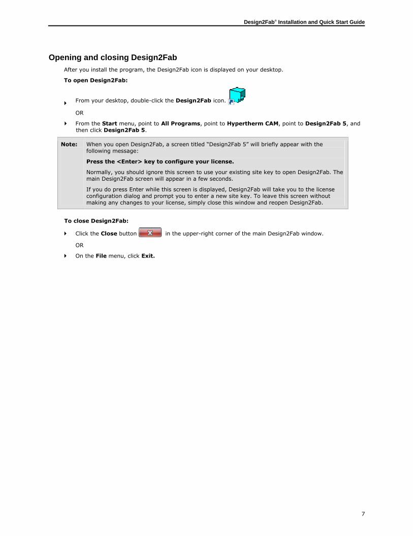
After you install the program, the Design2Fab icon is displayed on your desktop.
To open Design2Fab:
From your desktop, double-click the Design2Fab icon.
OR
From the Start menu, point to All Programs, point to Hypertherm CAM, point to Design2Fab 5, and then click Design2Fab 5.
Note: When you open Design2Fab, a screen titled “Design2Fab 5” will briefly appear with the following message:
Press the <Enter> key to configure your license.
Normally, you should ignore this screen to use your existing site key to open Design2Fab. The main Design2Fab screen will appear in a few seconds.
If you do press Enter while this screen is displayed, Design2Fab will take you to the license configuration dialog and prompt you to enter a new site key. To leave this screen without making any changes to your license, simply close this window and reopen Design2Fab.
To close Design2Fab:
Click the Close button in the upper-right corner of the main Design2Fab window.
OR
On the File menu, click Exit.
Design2Fab® Installation and Quick Start Guide
8
Design2Fab Quick Start Guide
Even though Design2Fab was designed with ease of use in mind, it can still be intimidating at first glance. This guide should give you a good understanding of the basic functions of Design2Fab.
This guide will walk you through the following tasks:
Opening, saving, and starting new jobs
Organizing your job using zones
Selecting and modifying fittings
Printing job and fitting information
Generating DXF output
Main Design2Fab window
When you launch Design2Fab, the main window will appear. The main window contains menus, the toolbar, the Entry Form window, and the Zones and Fittings list. From this screen, you can create jobs and zones, edit options and material lists, choose fittings, print reports, generate output, and utilize other Design2Fab functions.
The top section of the main window contains the main menu (File, Edit, View…) and the standard toolbar. The menus and toolbar will be used throughout this guide to perform specific tasks.
The Entry Form in the middle of the main window contains a library of predefined fittings. This view of the Entry Form is known as the Toolbox.
The Zones and Fittings list is located at the bottom of the main window. It displays the zones in your current
job and the fittings listed within those zones. When starting a new job in Design2Fab, there will be no zones listed and the fitting list will be empty.
Note: An in-depth discussion of Design2Fab menus and toolbars is beyond the scope of this guide. For more comprehensive information about Design2Fab features, consult the Design2Fab 5 User Guide. During installation, this document is placed in the following location:
C\Program Files\Hypertherm CAM\Design2Fab 5\Help\D2F5 User Guide.pdf
To open this document, you will need Adobe Reader.
Design2Fab® Installation and Quick Start Guide
9
System set up
Before starting a new job, it is advised that you configure some of the basic aspects of Design2Fab to meet your specific needs. You can do this using the Options dialog.
To adjust Design2Fab Options:
On the Edit Menu, click Options.
The Options dialog will appear. This dialog is divided into five tabs: General, Colors, Costing (Enterprise and Estimator only), Passwords, and PNL (Foreman and Enterprise only). For the purposes of this guide, we will discuss the General tab only.
General:
I will be working in: This option allows you to choose inches, centimeters, or millimeters. Selecting Centimeters or Millimeters will make all of your values metric (SI) throughout the software. Choosing Inches will make all of your values US standard.
Print numbers as: This option lets you specify whether to use either fractions or decimals in your measurements. Choosing 1/16 or 1/32 will round all of your measurements to the nearest 16th or 32nd of an inch, and will be displayed in printed format as 1/16 or 1/32. Keep in mind that choosing fractions may cause unwanted rounding errors if you are working with very fine tolerances. Choosing decimals such as .01 or .001 will round your measurements to the nearest hundredth or thousandth.
Load most recent job when starting: When selected, Design2Fab will automatically load the most recently opened job when you start the program again.
Show warning for unsaved fitting: When selected, Design2Fab will show a warning each time you return from the Fitting Entry window to the Toolbox without first saving your fitting. It is recommended that you check this box to avoid accidental loss of data.
3D Projection: Orthographic projection is the same as parallel line rendering in all 3D pictures. Perspective projection uses a vanishing point technique to create a more realistic 3D visualization.
Note: For more information on Design2Fab Options, please refer to the Design2Fab User Guide.
Starting a new job
When Design2Fab is opened, there will be no current job open. You must first create a job in order to save any of your fittings, print reports or generate output.
To create a new job:
1 On the File menu, click New Job.
The Create New Job dialog will appear.
2 Type “My First Job” in the File name box.
3 Click Open.
After clicking Open to create a new job, you will return to the main Design2Fab window. The name of your job will appear in the title bar of this window. Notice that the Zones and Fittings list at the bottom of the screen is still empty. Also, the Entry Form is displaying the Toolbox window, which contains numerous fitting templates.
At this point, we are ready to create zones for our first job.
Design2Fab® Installation and Quick Start Guide
10
Creating zones
This section of the guide will show you how to utilize zones to organize your job. Zones let you divide your job into categories. For instance, you could set up zones to represent project sites, different floors of a building, or months of the year—whatever helps you to best organize your job.
Note: In order to create or modify a zone, you must have a job open.
To create a new zone:
1 On the Edit menu, click Add Zone.
The New Zone dialog will open.
2 Type “First Zone” in the text box and click OK.
Your new zone will appear in the Zones and Fittings list at the bottom of the main screen.
From the Zones and Fittings list, you can add new zones, delete, rename, or copy existing zones, as well as select a
particular zone as your active zone for saving fittings. You can also quickly select fittings for editing from this window.
The name of your new zone will also appear in the Zone box in the standard toolbar at the top of the main window. This box
shows your currently active zone. Any fittings that are saved will be stored in this zone. To change the active zone, simply
click the drop-down arrow and select the desired zone from the list.
You can create as many zones as you want for a job:
Using the above steps, create another zone named “Second Zone”.
You should now be able to see both of your zones listed in the Zones and Fittings list. “Main” is a default zone and
cannot be deleted.

Design2Fab® Installation and Quick Start Guide
11
Selecting fittings
Design2Fab contains a comprehensive library of shapes for pattern layout and fabrication. You can choose from a list of
different fitting templates, which appear in the Toolbox view of the Entry Form in the middle of the main window.
Toolbox
This window is the starting point for selecting a fitting. The fittings listed already have predefined dimensions, metals, joints, seams, and gauges, which can be modified later.
To select a fitting:
Double-click the fitting.
The Fitting Entry window will automatically open, allowing you to modify the selected fitting. For now, click the Toolbox button to return to the Toolbox entry form.
You can move fittings around within the Toolbox by simply clicking and dragging a fitting. This can be useful if you frequently use the same templates. You can also change the name of a fitting template by highlighting the fitting in the Toolbox, right-clicking the fitting, and selecting Rename.
Important: The fittings listed in the Toolbox are common industry fittings that were drawn according to SMACNA standards. Typically, you will only need to edit certain aspects of the fitting, such as its dimensions, though you will find that the fittings can be fully customized to meet your needs.
After selecting your template, you will be ready to modify the fitting.
Modifying fittings
Once you have selected a fitting template, you can use the Fitting Entry window to begin modifying the dimensions and other characteristics of your fitting. You will also use this window to save fittings to your job. In order to help you fully understand the editing process, this guide will provide a walk-through using a sample fitting.
To modify a fitting:
Select the Square to Round fitting from the Toolbox by double-clicking it.
Fitting Entry window

Design2Fab® Installation and Quick Start Guide
12
The Fitting Entry window will appear, displaying a 3D picture of the fitting on the left side, a grid containing dimensions
and other details in the center, and a list of command buttons on the right.
General Grid
The general grid in the center of the window is divided into the following sections:
General: This allows you to edit the fitting name and specify the quantity of fittings needed. Design2Fab automatically assigns a unique fitting number to each fitting saved in a job. You can also add comments to the fitting.
Joints and Seams: This section lets you input the types of connectors and seams that you wish to use. By default, these values are set to “Raw”, meaning that no joints or seams have been selected. The number of boxes in this section will vary from fitting to fitting, depending on the complexity of the part. The characteristics of joints and seams can be found and modified in Shop Standards.
Material: The metal and gauge boxes have drop-down lists containing established values.
Accessories: For your fitting, you can specify the type of liner, insulation wrap, sealant, hangers, dampers and/or stiffener to use. Selecting “Raw” indicates that no accessory will be used.
Properties: Fitting properties such as shape, spacing and number of pieces can be input here. You can also choose whether to use inside, outside, or mean dimension values, as well as specify whether to allow material thickness.
Labor: (Enterprise only) For each fitting you can set the type of labor method that you use for various areas of costing.
Make some basic changes to your fitting:
In the General section, type “3” in the Quantity box.
In the Joints & Seams section, select 3” Collar from the drop-down list for Top Connector.
Dimensions Grid
Design2Fab uses common industry methods for entering your dimensions. If you point to a given box using your mouse, a
hint will appear that describes the dimension format for that field.
Change the size of your fitting:
Click the box next to Top Size.
Size can be input as either width x depth or diameter. Since the top of the fitting is cylindrical, we will adjust the diameter.
Type “15” in the box.
3D Picture
Design2Fab provides you with a 3D picture of your fitting. You can update this picture at any time to reflect any recent changes you have made.
To update the 3D picture:
Click on the 3D picture
The Square to Round fitting should now appear wider with a 3” top collar.
You can use the small arrow buttons in the 3D picture window to rotate the image and view it from any angle.
Clicking the Origin View button will bring the 3D picture back to the original view.
There are also three smaller views of your fitting in the lower left of the screen, which show the front
elevation, plan (top), and right side. These views are synchronized with the 3D picture.
Using Help
The Help command button in the right side of the Fitting Entry window can be very useful as you modify your fitting. Clicking this button will take you to Help topic that explains the currently selected fitting.
Each fitting’s Help topic contains a reference drawing followed by an explanation of the dimension variables associated with the fitting. Feel free to use this function as a guide as you enter your fitting details.

Design2Fab® Installation and Quick Start Guide
13
Saving your fitting
Once you have made all of the necessary changes to your fitting, it is time to save your part.
To save your fitting:
In the Fitting Entry window, click Save. Notice that the fitting now appears in the Zones and Fittings list. The fitting has been saved to the active zone, and is now a part of your job.
Note: You can go back and edit a previously saved fitting at any time.
To edit a fitting:
1 Select the zone that the fitting is saved in.
2 Double-click the fitting name in the Zones and Fittings list.
The fitting will be displayed in the Fitting Entry window for editing.
3 When all of your changes have been made, click Save.
Shop Standards
Shop Standards are user-definable material files that let you add, change or delete metals, gauges, liner, wrap, regular and round joints (connectors), rectangular and round seams, stiffener, sealant, vanes, hanger, and other elements that will be used when creating your fittings and printing your lists or reports.
You can access Shop Standards as follows:
In the Edit menu, select Databases and then Shop Standards.
OR
In the Fitting Entry window, click the Shop Standards button.
OR
Press F5.
This database is used to populate the general and dimension grids of the Fitting Entry window. It is also used for job costing and estimating, as well as in shear list and material reports.
The Design2Fab Shop Standards database is populated with default values that fully adhere to SMACNA construction standards.
Note: When you make changes to Shop Standards, the changes become effective immediately. This allows you to modify Shop Standards as you edit a fitting. After you edit Shop Standards, the grid fields in the Fitting Entry window are updated automatically with your new values, allowing you to continue your work uninterrupted.
You can add new items, such as metals, gauges, and connectors, or edit existing items in Shop Standards at any time.
To add a custom item to the Shop Standards database:
1 Click the appropriate tab in the Shop Standards window.
2 Click Insert Line.
In the box, type the name and details of your new item.
3 Click Close.
You will return to the Fitting Entry window. Your new value has been added to Shop Standards, and can now be selected in the General Grid.

Design2Fab® Installation and Quick Start Guide
14
Pattern
The Pattern window displays scaled 2D patterns that are generated from your 3D fitting.
To view the patterns for your fitting:
Click the Pattern button on the Fitting Entry window.
The Pattern window will appear, displaying a pattern preview on the left hand side of the window. In the upper right section of this window, there is a list of pattern pieces for the selected fitting.
The names of the pattern pieces appear first, followed by their quantity and gauge. The number of pattern pieces displayed (in this case there are 5 pieces) reflects the Number of Pieces specified in the Properties section of the General Grid.
Preview a different pattern piece:
Under Patterns (Qty), click the pattern name Top Collar.
Notice that the pattern preview in the left screen has changed. This preview now shows the top collar for your Square to Round fitting.
Below this section you can change pattern position on the blank, add excess to your blank, zoom in or out, flip your pattern horizontally or vertically, and select standard or maximum optimization. You can also output this specific fitting pattern directly to DXF.
For now, close this window and return to the Fitting Entry window.
Layout
The Layout function in Design2Fab previews all layout points for the current fitting.
To access the layout for your fitting:
On the Fitting Entry window, click the Layout button.
This window gives you the start and end X-Y points for each of the pattern pieces as well as their bend lines along with triangulation points and bend angles. The point of origin for the X-Y axis is the lower left corner of the pattern piece blank. From this point, the positive x-axis extends across the bottom of the blank in the positive direction, while the positive y-axis extends upwards along the left side of the blank.
Note that the pattern piece names that we previously saw in the Pattern window correspond to the names
listed in the layout window. Scroll down the page to view all of the coordinates and numbers for each pattern.
Costing
This feature is available in Design2Fab Estimator and Enterprise only.
The costing feature is a single-entry system that seamlessly integrates layout with costing and estimating. When you make changes to the details or dimensions of your duct fittings, those changes are automatically reflected in your costing information. This feature can be useful for management costing or for bidding jobs.
The costing and time components appear at the bottom of the main Entry Form.
This chart provides a summary of all metal, accessory, material, labor and fabrication costs. You can view costs for different aspects of your job by selecting Current Piece, Total Zone or Total Job from the drop-down box.
Note: The above costing figures are calculated from costing data contained in your Database (Shop Standards, Materials, and Per Piece Labor) and Hourly Rates. These can be found in the Edit menu.

Design2Fab® Installation and Quick Start Guide
15
In Design2Fab, the cost fields for metals, accessories, and materials as well as labor and fabrication are already populated with cost values based on SMACNA standards. You may need to change some values to reflect your actual costs. This will allow you to generate accurate cost estimates. You can modify your cost values in the Database and Hourly Rates sections.
To view your existing cost values:
1 From the Edit menu, open Databases and then Shop Standards.
2 Select the Gauges tab.
Notice that for each gauge of a particular metal, there is a column labeled $/Lb (or $/kg). Here you can insert the current cost of the item. Design2Fab will use this number to calculate certain costs throughout your job. Browse through some more tabs to see how other materials are priced. Now, let’s return to the main screen.
Saving and opening jobs
Design2Fab stores all of the information in your job as you work. When you save a fitting, create a zone or modify a database, your changes are automatically saved in the currently open job file (*.job).
To open an existing job:
1 In the File menu, select Open Job.
2 Select the desired file (.job) and click Open.
Printing reports
The print function in Design2Fab lets you print customizable reports for your job.
To print reports:
On the File menu, click Print.
OR
In the toolbar, click the Print button.
The print dialog will appear. First, make sure that the printer is correct. Next, from the Reports drop-down box, choose the type of report that you want. Some available reports include:
Fab Sheet w/ Patterns: prints a 3D picture of your fittings, information from the general and dimension grids, layout, and all patterns for your fittings.
Fab Sheet w/out Patterns: includes 3D picture, grid information, and layout.
Full size patterns: produces a full scale printout of your patterns (Foreman and Enterprise only).
Page size patterns: will produce a printout of your patterns scaled to fit the page.
Note that available reports vary based on the version of Design2Fab that you are using. You can also use the “Print Options” dialog to further customize your printouts.
Important: You must have a job open in order to use the print function.

Design2Fab® Installation and Quick Start Guide
16
Generating output
This feature is available in Design2Fab Foreman and Enterprise only.
At this point you have learned how to start a new job, add zones, select and modify fittings, view and edit databases and print reports. You are now ready to generate DXF output.
The DXF feature allows you to save fitting patterns and 3D pictures as standard DXF files. Exported DXF files can be used by many applications, and can be imported directly into any one of Hypertherm’s nesting solutions.
To generate DXF output for the current job:
1 Make sure that the job you wish to export is currently open.
2 On the File menu, select DXF Export.
The Create .DXF files window will appear (see below). When all options have been configured as needed, you will be ready to generate DXF output.
3 Press the Create DXF’s button.
A dialog box will appear confirming that your DXF files have been created and saved in the specified folder.
4 Click OK.
The Create .DXF files window
This screen includes several options, including:
Zone: You can create DXF files for an entire job (All Zones), or select a particular zone for export.
Fittings: When you select a particular zone for export, notice that a list of fittings in that zone appears in the Fittings box. By default, all fittings are selected. You can create a DXF file for a specific fitting by highlighting the fitting in this box. Clicking the All button will select all fittings, the None button will clear the selections.
Destination drive/folder: You can save your DXF file to the folder of your choice.
DXF Options: You can control the composition of your DXF files by selecting Pattern edge, Bend lines, Blank edge, and Seam edge. Generally, Pattern edge and Bend lines should remain selected.
File name: You can control how Design2Fab assigns file names to your DXF files. Selecting Short name (DOS) will automatically assign a short name (no longer than 8 characters) to your file. You can include job, zone, or fitting name in your DXF file name by clearing the short name box and then selecting Job, Zone and/or Ftg Name. Note that fitting number (Ftg#) will always remain selected.
Create folders for each metal/gauge: When selected, Design2Fab will create separate output folders for each different metal or gauge.
Create .pnl for exported drawings: When selected, Design2Fab will create a part list file (*.pnl) along with your output. The PNL is a tab–delimited text file containing a list of fittings in the job. Creating a PNL can be used to quickly import a list of parts into Hypertherm nesting applications.

Design2Fab® Installation and Quick Start Guide
17
Contacting Hypertherm
Address: Hypertherm 22 West Main Street Lockport, NY 14094 U.S.A.
Telephone: +1 (716) 434-3755
Fax: +1 (716) 434-3711
World Wide Web: www.hyperthermCAM.com
Email: Office hours:
[email protected] Monday to Friday 8:00 A.M. to 5:00 P.M. Eastern Time
Technical Support
Hypertherm is committed to providing you with the best overall product experience. This includes intuitive technical products and flexible options to fit your support needs. Our products are designed with superior quality and ease of use in mind, but we understand that issues do arise from time to time that need the backing of our support resources.
For current hours of operation, details about all support offerings, and a knowledge base, please visit our website:
www.hyperthermcam.com/support
In the United States and Canada, you can also contact technical support by phone or email at:
Phone: +1 (716) 434-3755 option 3 Email: [email protected]
If you are located outside the United States or Canada, please contact your account representative for more information.
Sales
Contact us for information about the latest Hypertherm products, the Software Subscription program, additional licenses, upgrade options and prices, and more.
In the United States and Canada, contact our sales department at:
Phone: +1 (716) 434-3755 x210
If you are located outside the United States or Canada, please contact your account representative for more information.

Design2Fab® Installation and Quick Start Guide
18
International Locations
America
Hypertherm (CAD/CAM Software) 22 West Main Street Lockport, NY 14094 USA +1 (716) 434-3755 Tel +1 (716) 434-3711 Fax [email protected]
Europe
Hypertherm Europe B.V. Vaartveld 9 4704 SE Roosendaal The Netherlands +31 (0) 165 596907 Tel +31 (0) 165 5969801 Fax [email protected]
Latin America
Hypertherm México, S.A de C.V. Av. Toluca No. 444, Anexo 1 Col. Olivar de los Padres Del. Álvaro Obregón D.F. C.P. 01780, Mexico +52 55 5681 8109 Tel +52 55 5683 2127 Fax [email protected]
Hypertherm Brasil Ltda. Rua Brás Cubas 231 Jardim Maia CEP 07115-030 Guarulhos, SP - Brasil +55 11 2409 2636 Tel +55 11 2408 0462 Fax [email protected]
Asia
Hypertherm (Shanghai) Trading Co., Ltd. Unit A, 5th Floor, Careri Building 432 West Huai Hai Road Shanghai 200052, PR China 86-21 5258 3330 /1 Tel 86-21 5258 3332 Fax [email protected] Hypertherm (S) Pte Ltd. 82 Genting Lane Media Centre Annexe Block #A01-01 Singapore 349567 +65 6841 2489 Tel +65 6841 2490 Fax [email protected]
Hypertherm Japan Ltd. 801 Samty Will Building 2-40 MNiyahara 1-Chrom Yodogawa-ku Osaka, 532-0003, Japan +81 (6) 6225 1183 Tel +81 (6) 6225 1184 Fax [email protected]
Hypertherm Korea Branch #3904 Centum Leaders Mark B/D 1514 Woo-Dong Haeundae –Gu Busan, Korea 612-889
+82-51-747-0358 Tel +82-51-701-0358 Fax [email protected]
Hypertherm (India) Thermal Cutting Pvt. Ltd. New No. 83, Old No. 52 Bazullah Road, T. Nagar Chennai, Tamil Nadu India 600 017 South/East: +91 99 4068 1650 Tel North/West: +91 99 5844 4984 Tel +91 (0) 44 2834 5362 Fax [email protected]

Design2Fab® Installation and Quick Start Guide
19
Index
A
Authorization code
obtaining, 6
using, 5
C
Closing Design2Fab, 7
Contacting Hypertherm, 17
Sales, 17
Technical Support, 17
Costing, 14
Creating zones, 10
D
Databases, 13
Design2Fab
authorizing, 5
closing, 7
installing, 4 main window, 8
opening, 7
user manual, location of, 7, 8
versions, 2
Dimensions, 12
DXF, 16
E
Enterprise, 2, 14, 16
Entry Form, 11
Estimating, 14
Estimator, 2, 14
F
Fitting Entry, 11, 14
Fittings
diagrams, 12
modifying, 11 selecting, 11
Foreman, 2, 16
G
Generating Output, 16
Grid
dimensions, 12
general, 12, 14
H
Help, 12
Hypertherm
Contacting, 17
Sales, 17
Technical Support, 17
I
Installing Design2Fab, 4
Introduction, 2
J
Jobs
opening, 15
saving, 15
starting new, 9
Joints, 12
Journeyman, 2
L
Layout, 14
Local installation, 5
N
Nesting software, 2, 16
Network installation, 5
New Job dialog, 9
O
Opening Design2Fab, 7
Options, 9
Output, 16
P
Pattern, 14
PNL, 16
Printing, 15
Q
Quantity, 12
R
Reports, 15
Request authorization code, 6
S
Seams, 12
Set up, 9
Shop standards, 12, 13
Site key. See Request authorization code
System requirements, 3
T
Technical Support, 17
Toolbox, 11
Z
Zones, 10

Hypertherm and Design2Fab are trademarks of Hypertherm, Inc. and may be registered in the United States and/or other countries.
For more information, contact your authorized Hypertherm dealer or visit www.hyperthermCAM.com.
© 2013 Hypertherm, Inc. All rights reserved. D2FMNL-0001