design standards for i, of transportation u.s. department
TRANSCRIPT

U.S. Departmenti, of Transportation
Federal AviationAdministration
-
Design Standards foran Aircraft Rescue andFirefighting Training Facility
Advisory Circular 150/5220-17A
Date: January 31, 1992

0U.S. lxparmmt
L, of Tmnsportation
FMUdAViOtblAdmidStIUtiOn
AdvisoryCircular
Subject: DESIGN STANDARDS FOR ANAIRCRAFT RESCUE AND FIREFIGHTINGTRAINING FACILITY
Date: l/31/92 AC No: 150/5220-17AInitiated by: us-120 Challfp
1. PURPOSE. This advisory circular containsstandards, specifications, and recommendations forthe design of an aircraft rescue and firefightingtraining facility utilizing either propane or aflammable liquid hydrocarbon (FLH) as the fuel.
2. CANCELLATION. This advisory circular(AC) cancels AC 150/5220-17, dated 4/l/88.
3. APPLICATION. Conformance withstandards and specifications contained in this ACis a prerequisite to receiving Federal grant-in-aidassistance for the design and installation of anaircraft rescue and firefighting training facility.The FAA recommends the use of this documentfor the design of non-federally assisted projects.
4. RELATED READING MATERIALS.Publications referenced within this advisorycircular can be obtained by writing to:
a. FAA Advisory Circulars (AC), U.S.Department of Transportation, Utilitization andStorage Section, M-443.2, Washington, DC 20590.
b. American Petroleum Institute (API),1220 L Street, N.W., Washington, DC 20005.
C. American Society of MechanicalEngineers (ASME), United Engineering Center,345 East 47 Street, New York, NY 10017.
d. American Society for Testing andMaterials ( A S T M ) , 1 9 1 6 R a c e S t r e e t ,Philadelphia, PA 19103.
American Water Works Association(A&A), 6666 W. Quincy Avenue, Denver, CO80235.
f. American Welding Society, Inc. (AWS),550 N.W. LeJeune Road, P.O. Box 351040,Miami, FL 33135.
!3 National Association of CorrosionEngineers (NACE), 1440 South Creek DriveHouston, TX 77084.
(NC&X),National Concrete Masonry AssociationP.O. Box 781, Herndon, VA 22070.
National Fire Protection Association(NgA), One Batterymarch Park, P.O. Box 9101,Quincy, MA 02269-9101
j. National Sanitation Foundation (NSF),3475 Plymouth Road, P.O. Box 1468, Ann Arbor,MI 48106.
k. Steel Tank Institute (STI), 666 DundeeRoad, Suite 705 Northbrook, IL 60062.

AC 150/5220-17A
Underwriters Laboratories Incorporated(UL)? 333 Pfingsten Road Northbrook IL 60062.Underwriters Laboratories Incorpdrated ofCanada (ULC), 7 Crouse Road, Scarborough,Ontario, Canada MlR3A9.
5. METRIC UNITS. To promote an orderlytransition to metric (SI)units, this AC containsboth English and metric dimensions. The metricconversions may not be exact, and pending anofficial changeover to this system, the Englishsystem governs.
hievawJ~~LEONARD E. MUDDDirector, Office of Airport Safety and Standards
ii

l/31/92 AC 150/5220-17A
TABLE OF CONTENTS
CHAPTER 1. PLANNING PHASE
Paragraph
1.2.
3.4 .
5.
6.7.8.9.
Page
Section 1. INTRODUCTION
GENERAL CRITERIA . . . . . . . . . . . . . . . . . . . . . . . . . .THE TRAINING FACILITY . . . . . . . . . . . . . . . . . . . . . . . .
Section 2. DERIVATION OF DESIGN PARAMETERS THAT SET TRAINING FIRE SIZE
TRAINING FIRE SIZE . . . . . . . .PCA/FIRE SIZE, DISC&GE'&TE AN;) ;)AR RELATIONSHIP' : . . . . . . . .
Section 3. SIZING BURN AREA STRUCTURES
SIZING METHODS . . . . . . . . . . . . . . . . . . . . . . . . . . .
Section 4. SITE SELECTION AND OPERATIONAL CRITERIA
AIRPORT OPERATIONAL FACTORS . . . . . . . . . . . . . . . . . . . . .ENVIRONMENTAL FACTORS . . . . . . . . . . . . . . . . . . . . . . . .VEHICLE MANEUVERING AREA . . . . . . . . . . . . . . . . . . . . . .U T I L I T I E S . . . . . . . . . . . . . . . . . . . . . . . . . . . . . .
10
Section 5. TRAINING FUEL STORAGE, CONSUMPTION, AND CONSERVATION
FLHUSE . . . . . . . . . . . . . . . . . . . . . . . . . . . . . .11: PROPANE USE12. OPERATIONAL R&&E~E,,& Fo;( THE TRAINING'FAc~L~T; : : : : : : : : :13-19. RESERVED . . . . . . . . . . . . . . . . . . . . . . . . . . . . .
CHAPTER 2. TRAINING FACILITY COMPONENTS
Section 1. GENERAL
20. BURN AREA STRUCTURE . . , . . . . . . . . . . . . . . . . . . . . .
Section 2. CONCRETE ALTERNATIVE FOR FLH
11
23
5
99
1011
11111414
15
21. RIGID BURN AREA STRUCTURE . . . . . . . . . . . . . . . . . . . . 1522. REFRACTORY CONCRETE CURB FO;: FLH-FIRED TRAINERS . . . . . . . . . . 15
. . .111

AC 150/5220-17A 1mP2
TABLE OF CONTENTS (CONTINUED)
ParamaDh Page
Section 3. FLEXIBLE MEMBRANE LINER ALTERNATIVE FOR FLH
23. FLEXIBLE BURN AREA STRUCTURE . . . . . . . . . . . . . . . . . . . . 1724. INTERIOR CRUSHED STONES FOR THE BURN AREA STRUCTURE . . . . . . . . 1925. BERM . . . . . . . . . . . . . . . . . . . . . . . . . . . . . . . . 19
Section 4. PROPANE SYSTEM ALTERNATIVE
26. PROPANE BURN AREA STRUCTURE . . . . . . . . . . . . . . . . . . . . 20
Section 5. SUPPORT COMPONENTS FOR TRAINING FACILITIES
27. CONCRETE APRON . . . . . . . . . . . . . . . . . . . . . . . . . . . 2028. OVERFLOW WEIR/DRAINAGE BOX FOR FLH-FIRED TRAINERS . . . . . . . . . 2129. AIRCRAFTMOCKUP . . . . . . . . . . . . . . . . . . . . . . . . . . 21
Section 6. SUPPORT SYSTEMS
30.31.32.33.34.35.36.
37.38.
40. STRUCTURAL STEEL . . . . . . . . . . . . . . . . . . . . . . . . . . 3341. CAST-IN-PLACE CONCRETE . . . . . . . . . . . . . . . . . . . . . . . 3342. REFRACTORY CONCRETE . . . . . . . . . . . . . . . . . . . . . . . . 3443. ELECTRICAL SYSTEMS . . . . . . . . . . . . . . . . . . . . . . . . . 3444. FLEXIBLE MEMBRANE LINER . . . . . . . . . . . . . . . . . . . . . . 3445. DRAINAGE FLOWNET . . . . . . . . . . . . . . . . . . . . . . . . . 3646. GEOTEXTILE FILTER FABRIC . . . . . . . . . . . . . . . . . . . . . . 3647. PIPING DISTRIBUTION SYSTEM FOR FLHS . . . . . . . . . . . . . . . . 3748. PIPING DISTRIBUTION SYSTEM FOR PROPANE . . . . . . . . . . . . . . 3749. STORAGE TANK FOR RECYCLED WATER . . . . . . . . . . . . . . . . . . 3850. PIPING DISTRIBUTION SYSTEM FOR WATER . . . . . . . . . . . . . . . . 38
FUEL/WATER SEPARATOR FOR FLH-FIRED TRAINERS . . . . . . . . . . . . 24CONTROL CENTER BUILDING AND PROTECTIVE WALL . . . . . . . . . . . . 24FUEL DISTRIBUTION SYSTEM FOR FLHS . . . . . . . . . . . . . . . . . 25UNDERGROUND STORAGE TANKS (UST) FOR FLHS . . . . . . . . . . . . . 27ABOVEGROUND STORAGE TANKS FOR FLHS . . . . . . . . . . . . . . . . . 27DESIGN OF SUPPLY PIPING SYSTEM FOR FLHS . . . . . . . . . . . . . . 28DESIGN OF COMPUTER CONTROLLEDDISTRIBUTION SYSTEM FOR LIQUID PROPANE (LP) . . . . . . . . . . . . 29WATER DISTRIBUTION SYSTEM FOR FLH-FIRED TRAINERS . . . . . . . . . . 30
- 39.RESERVED . . . . . . . . . . . . . . . . . . . . . . . . . . . 31
CHAPTER 3. CONSTRUCTION PHASE
iv

l/31/92 AC 150/5220-17A
TABLE OF CONTENTS (CONTINUED)
-
Figures/Tables Page
Figure l-l. Example of a training facility . . . . . . . . . . . . . . . 1Figure l-2. Typical relationship between control time and
Figure l-3.Figure l-4.Figure l-5.Figure l-6.Figure l-7.Figure 2-l.Figure 2-2.
Figure 2-3.Figure 2-4.Figure 2-5.Figure 2-6.
foam agent application rate for AFFF . . . . . . . . . . . . 2The critical fire areas . . . . . . . . . . . . . . . . . . 4Low discharge rates vs training fire area requirements . . . 7High discharge rates vs training fire area requirements . . 8Small training fire area vs estimated fuel needed . . . . . 12Large training fire area vs estimated fuel neeeded . . . . . 13Example of a concrete burn area structure (not to scale) . . 16Example of a flexible membrane liner burn areastructure (not to scale) . . . . . . . . . . . . . . . . . . 18Example of an aircraft mock-up . . . . . . . . . . . . . . . 22Metal material selection guide for mock-ups (reprint from NFPA 23
Figure 2-7.
Example location of a control center . . . . . . . . . . . .Example of an FLH storage tank, pump, supplypiping, and independent zonal delivery network . . . . . . .Example of a fuel/water delivery network with fourindependent delivery zones . . . . . . . . . . . . . . . . .
25
26
28
5
19
Table l-l.Table 2-l.
Burn area structures as a function of airport ARFF index . .Example gradation of backfill material for berm andadjoining inner ring section . . . . . . . . . . . . . . . .
APPENDIX 1. DESIGN AND CONSTRUCTION PRACTICESFOR PETROLEUM FUEL STORAGE TANKS
Section 1. PETROLEUM FUEL TANKS
1. AMERICAN PETROLEUM INSTITUTE (API)2. AMERICAN SOCIETY OF MECHANICAL ENGINEERS'(ASME; : : : : : : : : : : :3. AMERICAN SOCIETY FOR TESTING AND MATERIALS (ASTM) . . . . . . . . . .4. UNDERWRITERS LABORATORIES INC., (UL) . . . . . . . . . . . . . . . .
Section 2. VENTING SYSTEMS
5. AMERICAN PETROLEUM INSTITUTE (API)6. NATIONAL FIRE PROTECTION ASSOCIATION'(NFPA; : : : : : : : : : : : : :7. UNDERWRITERS LABORATORIES INC. . . . . . . . . . . . . . . . . . . .
Section 3. CATHODIC SYSTEMS
8. AMERICAN PETROLEUM INSTITUTE (API) . . . . . . . . . . . . . . . . .9. UNDERWRITERS LABORATORIES INC. (UL) . . . . . . . . . . . . . . . .10. STEEL TANK INSTITUTE No. STIP3 . . . . . . . . . . . . . . . . . . .11. NATIONAL ASSOCIATION OF CORROSION ENGINEERS STANDARD (NACE) . . . .
1111
222
2222
V

l/31/92 AC 150/5220-17A
CHAPTER 1. PLANNING PHASE
Section 1. INTRODUCTION
1. GENERAL CRITERIA. The facilitydescribed in this AC is intended to provideaircraft rescue and firefighting (ARFF) servicepersonnel with realistic training in the applicationof extinguishing agents on an appropriately sizedfire area using ARFF vehicle(s) or other agentapplication devices comparable to those used attheir airport. Figure l-l illustrates a genericlayout of such a training facility. The majorcomponents are discussed in detail in the AC.
2. THE TRAINING FACILITY.
a. General. The facility is composed ofthe burn area structure, the ARFF vehiclemaneuvering area, the various supportcomponents, and the support systems. Thephysical area needed for each of these itemsmakes up the total land area required toaccommodate a realistic training facility.
Support Systems:Control Center(Building for propaneProtective Wall forFLH-Fired Trainer),Fuel & WaterStorage Tanks,Fuel/WaterSeparator
Service/Maintenance,Vehicle Surface
b. Burn Area Structure. The fire area,termed the burn area structure, is the focal pointof the training facility. It is designed specificallyto create a realistic aircraft accident fireenvironment and to contain training substances.Its size is a function of the extinguishing agentapplicator discharge rates to be used for trainingexercises.
C. ARFF Vehicle Maneuvering Area. Thisarea physically surrounds the burn area structureand shall be large enough to allow for the tacticaloperation of ARFF vehicles as they approach theburn area structure and the realistic deploymentof personnel using hand lines.
d. Support Components. Thesecomponents make up the functional units neededto implement the simulation of various types ofaircraft fires and to recycle spent mixtures ofchemicals, water, and FLH if necessary. Theaircraft mock-up is a basic support componentand may be either fried or mobil.
ARFF Vehicle
-.-----a.
//
.’2
.’
. -.-.-,,, M a n e u v e r i n g A r e a
Burn Area
Support Components:Crushed Stones,Mock-up, ConcreteApron, OverflowDrain
Figure l-l. Example of a training facility
1
AC 150/5220-17A l/31/92
e. Support Systems. These systems are thefunctional units needed to implement the trainingfire simulation. For example, the control centeris a support system. Each support system is
composed of individual support components thatmakeup a system, e.g., the fuel distribution systemconsists of a storage tank, pumps, associatedpiping, etc.
Section 2. DERIVATION OF DESIGN PARAMETERS THAT SET TRAINING FIRE SIZE
3. TRAINING FIRE SIZE. To be acceptable aswell as meaningful, actual or simulated aircraftfire suppression training shall present thefirefighter with a realistic, challenging aircraft fire.In addition, the fire shall be, or give theappearance of being, extinguishable with the firesuppression equipment that a proficient firefighteris expected to use in an actual aircraft emergencyat the assigned airport. Discussed below arethree interdependent variables which effect thesetwo requirements.
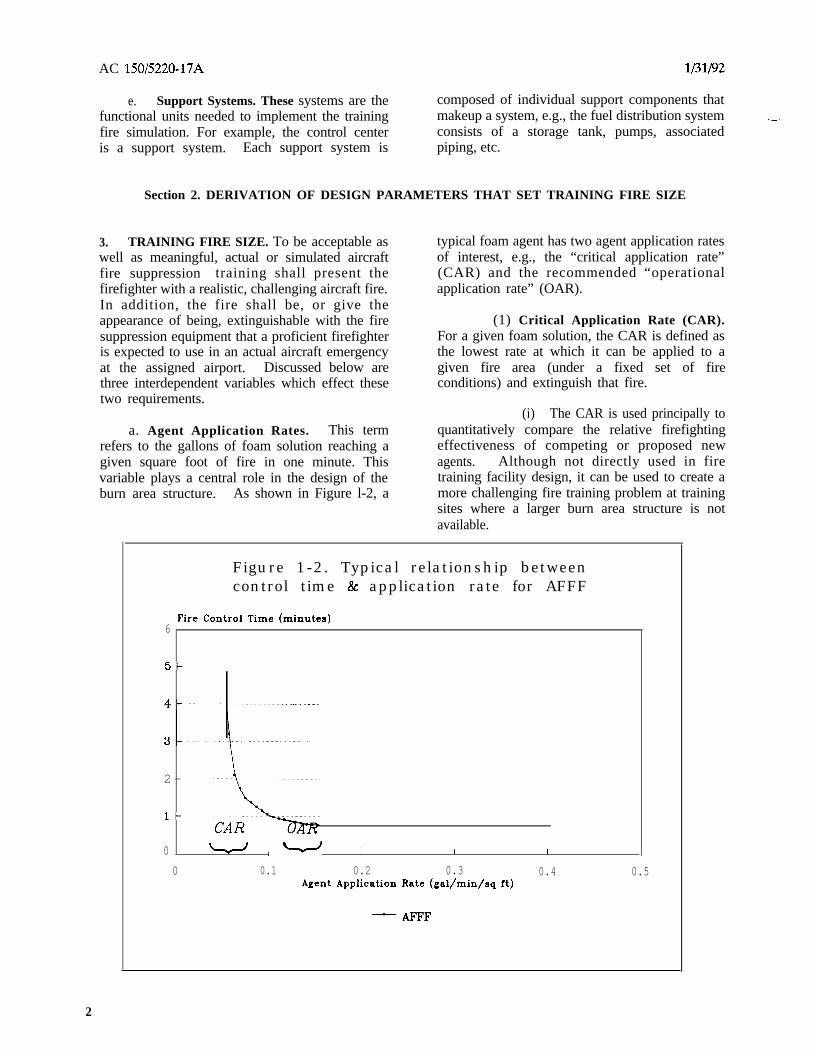
a. Agent Application Rates. This termrefers to the gallons of foam solution reaching agiven square foot of fire in one minute. Thisvariable plays a central role in the design of theburn area structure. As shown in Figure l-2, a
typical foam agent has two agent application ratesof interest, e.g., the “critical application rate”(CAR) and the recommended “operationalapplication rate” (OAR).
(1) Critical Application Rate (CAR).For a given foam solution, the CAR is defined asthe lowest rate at which it can be applied to agiven fire area (under a fixed set of fireconditions) and extinguish that fire.
(i) The CAR is used principally toquantitatively compare the relative firefightingeffectiveness of competing or proposed newagents. Although not directly used in firetraining facility design, it can be used to create amore challenging fire training problem at trainingsites where a larger burn area structure is notavailable.
Figure 1-2. Typical relationship betweencontrol time & application rate for AFFF
6Fire Control Time (minutes)
5-
2-
l-
0 w ,- I I I
0 0.1 0.2 0.3 0.4 0.5Agent Application Rate (gal/min/sq ft)
-AFFF
2

l/31/92 AC 150/5220-17A
(ii) The CAR is also used indetermining which foam agent is more cost-
- effective. For example, if the CAR of a “lowpriced” foam concentrate results in the use ofmore agent per square foot of fire extinguishedthan its competitor, it may turn out that the“higher priced” foam concentrate with a lowerCAR is really cheaper in terms of dollars persquare foot of fire suppression capability.
equipment and agent combination can beexpected to control in one minute can becalculated. In other words, the total fireextinguishing capability in terms of agent volume,time for application, and maximum fire area thatcan be extinguished is defined.
(2) Operational Application Rate(OW.
(i) Figure 1-2 also shows that thetypical recommended OAR is approximately threetimes the CAR of a given foam agent for a givenfuel fire. This relationship was established byextensive testing. It has also been found to beoperationally practical in terms of the uncertaintyof the conditions found at a typical fire site, thedesired fire control time, the average fire fighter’sskill, and the practical amount of agent that canbe immediately available at an aircraft accident.
(ii) It can also be seen fromFigure 1-2 that increasing the recommended OARwill generally reduce the fire control time.However, greatly exceeding the recommendedOAR will consume agent with no appreciableimprovement in fire control time, i.e., more is notnecessarily better. On the other hand, as theOAR approaches the CAR, control time isprolonged. Hence, a more challenging firesituation can be created in the same sized burnarea structure by reducing the OAR being usedby a trainee. However, if it falls below the CARthe fire cannot be extinguished in a reasonabletime with that agent.
C. Critical Fire Areas. Figure 1-3 is arepresentation of the relationship between thetheoretical critical fire area (TCA), the practicalcritical area (PCA), and a large aircraft. Theactual size of the TCA is a function of the lengthand width of the specific aircraft of interest.Fires outside the theoretical critical area have noimmediate impact on the life safety and rescueproblem at the aircraft. The PCA is defined asan area approximately two-thirds of the TCA forany given aircraft. It is the minimum area thatthe first responding ARFF units need to keepfire-free during the aircraft evacuation process.Hence, the PCA is used in aircraft rescue andfirefighting system planning to quantify thetactical and logistical aspects of the problem.Therefore, it is vital in ARFF training facilitydesign.
4. PCA/FIRE SIZE, DISCHARGE RATE ANDOAR RELATIONSHIP.
a. Logistics and Tactics. The initialoperational objective of the ARFF service is toprovide a viable evacuation route for passengersto exit from the aircraft through the PCA
b. Agent Applicator Discharge Rates.Discharge rates are used to describe or specify thedesired capability of a firefighting apparatus todeliver agent from a specified applicator, e.g.,turret, hand line, or bumper turret. Hence, thereis a notable difference between discharge ratescommonly specified for equipment performanceand the agent application rates discussed above.There is, however, an important relationshipbetween these two terms. For example, if theagent discharge rate, the usable agent tankvolume of a given firefighting apparatus, and theOAR (for the agent that is to be used) areknown, the size of the fire area which this specific
(1) This requires the ARFF service tohave the capability to at least control/extinguishfires within that area in one minute or less afterthe first application of agent. Therefore, there isa need to quantitatively define the logistical andtactical requirements of the PCA, which in effect,defines the minimum ARFF service requirementsfor a given aircraft size.
(2) By drawing on the informationdeveloped in the preceding paragraphs we havethe means to quantify the ARFF servicerequirements and to relate that result to burnarea structure requirements. For example,Table l-l provides a series of calculated PCAs byaircraft size and the literature (manufacturer’s orR&D) provides the OAR for generic foam agents,e.g., AFFF = 0.13 (aqueous film forming foam),FPF = 0.16 (fluroprotein foam), and PF = 0.20
3

AC 150/5220-17A l/31/92
,
T h e o r e t i c a l C r i t i c a lFire Area (TCA)
P r a c t i c a l C r i t i c a lFire Area (PCA)
Wind Direct ion
F i g u r e l-3. T h e c r i t i c a l f i r e a r e a s
(protein foam). With this information, therequired capability of an ARFF vehicle neededfor a specific PCA can be quantitatively specified.That is, the agent volume to be carried and theoptimum discharge rates for the agent applicatorscan be calculated, assuming of course, efficientapplication by the operator.
b. Fire Size for Training. It is generallyaccepted that if training is to be meaningful, itmust be a practical representation of theoperational task. Hence, it follows that ideally atraining facility for a given aircraft size shouldhave a burn area structure equal to the PCA ofTable l-l or should be at least able to present asimulated fire extinguishing task that a traineewill perceive as an equal challenge.
(1) Available land or other constraintsmay make it impractical to provide a trainingfacility with the large burn area structuressuggested by Table l-l. However, if the dischargerates of the agent applicators to be used intraining are kept in strict proportion to theavailable burn area structure, meaningful training
can be accomplished. Therefore, the size of aburn area structure can also be based on theproportional relationship between the actual orsimulated fire area, the total discharge rate of theagent applicator(s), and the OAR of the agent tobe used. In other words, when the available burnarea structure is known (and fixed) and test dataor the literature (manufacturer’s or R&D) providethe OAR for the agent to be used, theappropriate agent applicator discharge ratesrequired for meaningful training on the fire areaavailable can be calculated.
(2) This strict applicator discharge rateversus available or simulated fire area relationshipshall be maintained. Otherwise, if the OAR usedin training is too high, the trainee will not bechallenged --- only led to believe that the neededskills have been acquired. Conversely, if theOAR is too small in relation to the burn areastructure, the fire will go out only after allavailable fuel has been consumed or turned off,not because of the trainee’s effort or skill. Ineither case, no valuable training will have beenobtained for the resources expended.

l/31/92 AC 150/5220-17A
Section 3. SIZING BURN AREA STRUCTURES
-
5. SIZING METHODS. Three methods aredescribed in this section to size a burn areastructure for aircraft firefighter training. The firsttwo are applicable to burn area structuresconstructed for the use of FLHs. The firstmethod, referred to as the Airport ARFF IndexMethod, is based on the PCA of an averageaircraft size that is common to the airport. Thesecond method, referred to as the Discharge RateMethod, is based on the total discharge rate ofthe agent applicators, e.g., ARFF vehicle turretand/or handlines, that are going to be used intraining. The latter method permits airports withlimited land area or environmental constraints onthe usable fire size to engage in meaningfultraining by limiting the agent application rates tothat appropriate to the available training fire.The third method, referred to as the EmpiricalArea Simulator Method, is also based on theagent application rate/fire area relationshipsgoverning-the two methods where free burningFLHs are used. However, it takes advantage ofthe new “fire simulator” technology usingpropane, that allows control of the apparent fire
extinguishing rate. Thus, it permits the use ofdesired agent application rates on a smaller totalfire area than that required where a free burningFL,H is used. In all cases the Airport ARFFIndex Method sets the upper limits for the squarefootage of the fundable burn area structure.
a. Airport ARFF Index Method. The sizeof a burn area structure using the Airport ARFFIndex Method shall be in accordance with thepractical critical fire area (PCA) of Table l-1 forthe given airport ARF’F index.
(1) Although the size of the PCA fora specific aircraft is a function of the fuselagelength and width, it has been found that foreconomies of design, the use of average aircraftdimensions, based on operationally similar groupsof aircraft, provides technically acceptable valuesfor burn areas which are to represent airportARFF indexed PCAs.
lirport O v e r a l l Average Practical Rectangular CircularAircraft Fuselage Critical Burn Burn
ARFF Lengths Width Fire Area AreaIndex Area(PCA) (L/W=4/3) DiameterA/ Lower Average Upper
(feet) (feet) (feet) (feet) (sq. feet) (feet) (feet)
GA-1 30 38 45 6 1,171 40 x 30 39
GA-2 45 53 60 10 1,775 49 x 36 48
A 60 75 90 10 5,527 86 x 64 84
B 90 108 126 10 7,959 103 x 77 101
C 126 143 160 10 10,539 118 x 89 116
D 160 180 200 20 14,475 139 x 104 136
E 200 225 - - - 20 18,090 155 x 116 152
lJ Airport ARFF index dimensions are defined in AC 150/5210-6C, Aircraft Fireand Rescue Facilities and Extinguishing Agents.
Table l-l. Burn area structures as a function of airport ARFF index

AC 150/5220-17A l/31/92
(2) Table l-l presents the results ofthe PCA calculations needed in this method. Thetwo columns on the right side of that tableprovide quick square footage estimates for theappropriate sizing of a FLH burn area.
b. Discharge Rate Method. The size ofthe burn area structure using the Discharge RateMethod shall be in accordance with eitherfigures l-4 or l-5.
(1) Burn area structures sized by thismethod are acceptable when available land orother constraints make it impractical to providea burn area equal to the area of the PCAsuggested by Table l-l. By keeping the dischargerates of the agent applicators in strict proportionto the available fire area, equivalent and effectivetraining can be performed.
(2) Figures 1-4 & 1-5. Figures l-4 andl-5 provide graphic solutions for the burn areastructure square footage prescribed under thedischarge rate method for known generic foamagents. Alternatively, the appropriate squarefootage for a burn area structure may bedetermined by dividing the discharge rate of theagent applicator(s) to be used by the OAR of theagent to be used.
NOTE: The area derived from figure l-4 or l-5is only for the burn area structure.Additional land area is necessary for theother elements that comprise thetraining facility. Two examples of howto use these figures are presented below.
(i) Limited Land Area. Wherethe maximum available land for the installation ofa new FLH-fired training facility is smaller thanrecommended by table l-l, or an existing smallfacility is being retrofitted, the largest appropriatedischarge rate for that burn area structure can bedetermined from either figure l-4 or l-5. Firstenter along the burn area structure squarefootage axis (horizontal) and proceed vertically upto the appropriate generic foam OAR line. Thenproceed directly to the left to intersect thedischarge rate axis (vertical). For example,trace 1 of figure l-4 illustrates that a dischargerate of 195 gpm (738 L/m) is the maximumpermissible rate for realistic training for a burn
area structure of 1,500 square feet (139 squaremeters) using AFFF. This area could beaccommodated by a 44 x 33-foot rectangle (13.5x lo-meter) or a 44-foot diameter circle (13.4-meter).
(ii) Fixed Discharge Rate. Wherethe minimum available discharge rate is fmed (asby a vehicle turret), the appropriate squarefootage can be determined by entering the samefigures in reverse. First enter along the dischargerate axis (vertical) and proceed directly to theright to the appropriate generic foam OAR line.Then proceed vertically down to intersect theburn area structure square footage axis(horizontal). For example, if two vehicles with750 gpm (2 839 Wmin) discharge each are to beused, trace 2 of figure l-5 illustrates that a burnarea structure of approximately 11,540 square feet(1 072 square meters) is necessary for themeaningful use of a discharge rate of 1,500 gpm(5 678 L/min) using AFFF. This value isacceptable for land limited training facilities atairports with an ARFF D or E index as long asfirefighting training operations do not exceed atotal discharge rate of 1,500 gpm (5 678 L/min).Similarly, larger or smaller burn area structurescan be derived for ARFF training operationswhere larger or smaller discharge rates areexpected. However, for economies ofconstruction, operations, and maintenance, theupper limit for burn area size is set by table l-l.
C. Empirical Area Simulator Method. Theburn area structure for ARFF training facilitiesusing a computer-controlled, propane-fired, FLHfire simulator shall be sized as follows:
(1) For ARFF index A and Bsimulations, the burn area shall be a circle witha diameter of least 100 feet (-l/+2 ft). A squareor a rectangle, which will accommodate therequired aircraft mocku
Pof an approximately
equivalent area (7,855 ft ) is acceptable.
(2) For ARFF index C through Esimulations, the burn area shall be a circle witha diameter of least 125 feet (-l/+3 ft). A squareor a rectangle, which will accommodate therequired aircraft mockup, of an approximatelyequivalent area (12,273 ft2) is acceptable.
6

1/31/92
-eGoa-~...~
~a~.
.c()
.!'a...~
00~
010(Y)
~
, :1
00(W)
,1
010
(\I
00C\I
:'\I
IIIII
1-::tt:ICbIt.)
I~' I
I
IIIIII
II
010~
II ~: Q)~ (.)
~ ~: ...: ~--\ : --T
~ I ~
~ I ~
~ I ~: I :
\~:I :.I ~
.':
~'.;
1i ~,~~
\~:
00~
010
0
00~
000C\I
0010
C\I
-...ee0-
O!10-,-~
co~-'0e~
~coe~0-
O!0-'-c
~~m
+
--go~""-Ec.a0"!0.LL0.
--0-~Ea.a
<0"":0.u.0-LL
+
--co~Ea.atY)~
0.LLLLLL<
AC 150/5220-17A
-G)......j-tUErJ)
...0Q)C
"0Cco:
.c..Q)OJ...as.c
urJ)
0
..C G-"E G,E~O'G...=~~100,.. .'0
~ ....E"Q.O'o.00pp
7

8
AC 150/5220-17A
-.'a~..~0.c..--eGo~-....-.~-.
.c0.-'a-...~
10 ~
~
(W) (\I
I'1
1
1
1II1
~:I
Q) 1C) 1
~ 1
::'1I111I
I1111
-
('II'tt:Q)()
~----
0
0010
C\I
00010
0-;:-0 ~IO.!
C\I ~,- ~.
~co
O~0'0
0 !0'5,- co
~~.
0 !0 .10 cr ~
m
000La,-
0010, y-
0000C\I
--co~,Ec.a0C\I0.LL0-
t
--C"0
EC-O»
CD"'":0.u.a..u.
+
+
--co0
Ea.a
(')""';0.LLLLLL<
-Q)~~~-I-~E~0
Q)CI~'"a,-CI~'"
.cu0
0
1/31/92
..c ~
E~,E~o-.88=~~OI
0.00
~.
. ..E"0.0-a800..:..:

l/31/92 AC 150/5220-17A
Section 4. SITE SELECTION AND OPERATIONAL CRITERIA
-
6. AIRPORT OPERATIONAL FACTORS.
a. Airside Operations. The training facilityshall be sited:
(1) Outside of all restricted areas notedin AC 150/5300-13, Airport Design, and AC 129-29, Criteria for Approving Category I and IILanding Minima for FAR 121 Operations.
(2) Where smoke and the associatedthermal plume will not hinder aircraft operationsor air traffic control (ATC) tower’s surveillance ofthe movement area.
(3) Where the aircraft mockup (e.g.,tail height) and support components (e.g.,buildings) will not interfere with navigational aids.
b. Other Siting Items. The training facilityshall be clear of:
(1) Airport buildings and public vehicleparking lots for a distance of 300 feet (91 m).
(2) Residential areas for at least1,000 feet (305 m).
7. ENVIRONMENTAL FACTORS. A detailedreview of applicable Federal, State, and localenvironmental and fire regulations is necessary forthe effective planning, design, and operation of atraining facility. Many jurisdictions haveregulations that impose effluent discharge limits,air quality operating restrictions, e.g., volatileorganic compound (VOC) regulations, and facilityfire prevention inspection programs. Advancedknowledge of these requirements will help avoiddelays in construction and the curtailment ortermination of training. Additionally, both near-and long-term land requirements for the trainingfacility and the intended use of adjacent landsshould be identified and addressed early in thesite selection process.
a. Literature Search.
(1) Clean Water Act (CWA). Asprovided under Section 303 of the CWA, Federalregulations require that all States develop waterquality standards which have been approved bythe U.S. Environmental Protection Agency(USEPA). Numerous sections of the CWA
outline provisions for other Federal regulations toensure that State water quality standards areachieved. Regulations include the NationalPollutant Discharge Elimination System (NPDES)program (Section 402), Effluent Limitations(Section 301), Toxic and Pretreatment EffluentStandards (Section 307), Resource Conservationand Recovery Act (RCRA), ComprehensiveEnvironmental Response, Compensation, andLiability Act (CERCLA), and SuperfundAmendments and Reauthorization Act (SARA).Regulations required by the FAA include theNational Environmental Policy Act (NEPA) andFAA Orders 5050.4A and 1050.1D.
(2) Computer Search of EnvironmentalRegulations. The U.S. Army Corps of Engineersmaintains the subscription data baseEnvironmental Technical Information System(ETIS) which summarizes Federal, State, andlocal environmental regulations. The ETIS iscomprised of several subsystems, including theComputer-Aided Environmental Legislative DataSystem (CELDS), which contains abstractsupdated bimonthly of all the environmentalregulations of the Federal Government, the 50States, District of Columbia, and Puerto Rico.CELDS permits an easy but comprehensive searchof pertinent regulations that may impact thefacility. For assistance using ETIS, contact theETIS Support Center, University of Illinois, 990West Nevada, Urbana, IL 61801, (217) 333-1369.For information about ETIS, contact U.S. ArmyConstruction Engineering Research Laboratory,(217) 352-6511, extension 447.
b. Topography. Relatively flat land offersboth improved runoff control and lower sitepreparation cost.
C. Use of FLHs. Candidate sites for atrainer using FLHs should evaluate the site’s:
(1) Proximity to Water Supply Wellsand Wetlands. Water supply wells and wetlandsin the vicinity shall be protected by siting thetraining facility as far as possible from them.Prior to any construction, the selected site shallfirst receive approvals by the Federal, State, andlocal environmental authorities. If sited in thevicinity of a well, the site should be on thedowngradient side of the well.
9

AC 150/5220-17A l/31/92
(2) Soil Permeability. The presence ofa natural or the addition of a low permeabilityconfining layer such as clay or silt below the burnarea structure and its immediate area helps tolessen the downward migration of inadvertentreleases of FHL fuels.
(3) Flood Plain. Training facilitiesshould be sited above the loo-year flood plain asdefined in FAA Executive Order 11988. Thislessens the possibility of washing contaminatesout of containment areas and degrading the localsoil and groundwater.
(4) Mitigation of EiBuent Discharge toNearby Streams. Training facilities shall includecontainment measures to preclude overland accessto perennial streams by inadvertent release ofFHL fuels. This access creates an environmentalrisk under direct low-flow conditions to such areceiver. Any effluent discharge into “navigablewaters” as defined by USEPA requires a permitunder section 402 of the Clean Water Act(NPDES).
d. Mitigation of FLH Quantities. Thegreatest harm to groundwater and soil qualities isattributed to FLHs released directly onto the soilduring training. Hence, the simplest mitigationmeasure for maintaining groundwater and soilqualities is to reduce the amount of fuel placed inthe burn area. Only that amount of fuel neededto create a training fire of the desired durationand intensity should be placed in the burn areastructure for each training session. In practicethere should be very little fuel remaining in theburn area structure after fire extinguishment. Toassist this effort, a means shall be provided forthe training officer to closely monitor the quantityof fuel allowed into the burn structure fortraining. Paragraph 10(b) and figures l-6 and l-7provide guidance on estimating fuel quantities.
e. Use of Propane. The use of a propane-fired trainer to simulate a FLH fire will eliminatethe hydrocarbon/water/agent discharge anddisposal problems associated with FLHs. Thistype of simulator will also minimize air pollutionproblems. In addition, the rapid automatic ormanual shutdown capability offered by thecomputer system is a significant safetyenhancement as well as a versatile tool for therapid recycling of a given training scenario by theinstructor.
8. VEHICLE MANEUVERING AREA.
a. Sizing. Facilities intended for vehicleoperator and/or turret operator training shall havea vehicle maneuvering area. For long-term costeffectiveness, the area should allow for theoperation of future vehicles with more demandingoperational characteristics.
-
(1) Turret Discharge. The area shallaccommodate the full turret discharge range whiledischarging dispersed and straight stream patternsduring stationary and pump and roll operations.
(2) Vehicle Mobility. The area shallaccommodate the ARFF vehicle turning radius,backup requirements, and, with the longestvehicle parked perpendicular to the burn areastructure, passage of other ARFF vehicles.
(3) Approach Path. There shall bemore than one approach path to the burn area.
b. Vehicle Maneuvering Surface.
(1) Soil Bearing Capacity. Soil bearingcapacity, treated if necessary, shall exhibit goodload bearing capacity of fully loaded ARFFvehicles operations and withstand the acceleratingand decelerating traction forces and turningactions of wheels without severe rutting damage.
(2) Sloped Surface. To reduce thechannelled rainfall and/or snow melt load on thedrainage system, the maneuvering surface shouldsloped as follows:
(i) For facilities with a berm, slopeaway from the burn area structure to divertrunoff.
(ii) For facilities with a concretecurb, slope in two directions. The inner section(apron) up to ten feet (3.0 m) shall slope towardsthe concrete curb with the outer section slopedaway from the burn area. If the apron is paved,a smooth transition shall be provided between itand the outer ground surface.
C. Paved Access Roads. If the trainingfacility access road is directly connected to anaircraft operational area, it shall be paved for atleast the first 500 feet (152 m) from the edge ofthe operational area. Paving this strip lessens thechance for foreign object damage (FOD) in areas
10

l/31/92 AC 150/5220-17A
intended for the movement of aircraft due to should be a component of the site selection“tracking” of objects. Paved access roads shall process. Their utilization simplifies the operation
------ have signs in accordance with AC 150/5340-18, of a training facility and, if permitted, effluentStandards for Airport Sign Systems, latest edition. disposal. Where a mobile mockup is to be used,
consideration should be given to the accessibility9. UTILITIES. The availability of electricity of utilities for the resupply of consumables andand water utilities within 900 feet (275 m) and where necessary the disposal of retained effluent.access to a sanitary sewer within 300 feet (91 m)
Section 5. TRAINING FUEL STORAGE, CONSUMPTION, AND CONSERVATION
10. FLH USE. The fuel type and quantityappropriate for the intended aircraft firesimulation, (evenly distributed over the burn areastructure) is as essential to meaningful training asis the proper applicator discharge rate/fire arearelationship.
a. Fuel Quantities. The total fuel neededfor a meaningful FLH training fire should beviewed as three separate quantities, each havinga specific purpose.
(1) Preburn. This quantity should besufficient to provide a 30-second pre-burn overthe entire area before extinguishing operationsstart. This pre-burn is needed to ensure that thefire area is fully involved and that the fuel surfacetemperature is sufficiently high to sustain achallenging, stabilized fire.
(2) Control time. This second quantityincludes at least enough fuel to ensure that theestablished fire can burn beyond the pre-burntime, at full intensity, over the unextinguishedportions of the fire area for the duration of thetraining session, usually one minute. Without thissecond quantity, the fire will self-extinguish in lessthan one minute giving the impression that thetrainee was successful.
(3) Post-burn. Although small, thisquantity will ensure that the trainee achieved thetraining objective, i.e., extinguished the fire in thepractical critical fire area within one minute.This third quantity allows the fire to burn beyondthe desired control time when the trainee isunable to successfully extinguish it. Hence, theinstructor has indisputable evidence thatadditional training is needed.
b. Estimates of Total Fuel Quantity.Figures 1-6 and l-7 are intended only as aconvenient means of estimating the fuel quantitiesfor typical FLH training fires. The quantities
shown are for a single training fire and are basedon the fuel consumption rate of a free-burningfire for Jet-A aviation fuel, i.e., approximately0.15 gal/ft2-min.
C. Fuel Savings. All three of the fuelcomponents discussed above offer potential fuelsavings through the refinement of the trainingfacility operational procedures and the proficiencyof the trainees. For example, if the pre-burn firecan be established quickly over the entire firearea, the quantity of fuel used can approach thatneeded for the 30 second pre-burn time. Astrainees become highly proficient, i.e., consistentlyextinguishing the fire in less than the desiredcontrol time, both control time and post-burnfuel quantities can also be reduced.
d. Wind Effects. Grossly asymmetric firesare the result of the FLH drifting under theinfluence of wind forces. This phenomenareduces the fire area, varies flame heights, andcauses uneven heats and excessive smoke. Tomitigate this problem, a crushed stone surfaceshould be used which will protrude partiallyabove the liquid fuel layer, e.g., l/2 to 1 inch(1.25 to 2.5 cm).
11. PROPANE USE. The quantity of propaneappropriate for the simulation of the intendedFLH fire (evenly distributed over the burn areastructure) is also essential for the creation of arealistic training fire. In addition, as the fire isattacked by the trainee, the appearance of theproper applicator discharge rate/fire areacontrol/control time relationships shall bemaintained.
a. Propane Quantity. The use of liquidpropane effects the planning for fuel quantityrequirements in two ways.
11

Figure 1-6. Small training fire area vsestimated fuel needed
Training fire area (sq ft)3500 1
0 100 200 300 400 500 600 700 800 900 1000Eetimated fuel:JET A or equivalent (gal)
-- 30 set + 90 seconds + 30 set + 2 minutes
+ 1 min + 2 minutes +-- Preburn + Training
Discharge: handline or small turret1 . 0 gal - 9 . 7 8 l i t e r s1.0 sq ft - 0 . 0 9 9 sq m e t e r

5
20
15
IO
5
0
Training fire area (sq ft) (thousande)
$31000
Figure 1-7. Large training fire area vsestimated fuel needed
2000 3000 4000 5000 6000 7000 8000Estimated fueLJET A or equivalent (gal)
- 30 set + 90 seconds
+ 1 min + 2 minutes
+ 30 set + 2 minutes
-Q-- Preburn + Training
1 . 0 gal - 3 . 7 8 liters1.0 sq ft l 0.093 sq meter
Discharge: large or multi-turret
1
-

AC X50/5220-17A l/31/92
(1) First, it eliminates the need for thepre-burn and post burn fuel quantities. This isbecause the propane burner control system willmeter propane into the burn area at anadjustable, predetermined rate. Hence, wheninitiated, the fire will start almost instantly overthe entire portion of the burn area selected bythe instructor. Thus, there is no pre-burn timerequired to obtain a stabilized, fully involvedscenario. The fire will then continue to burn atthe proper intensity over the preselected portionof the burn area until correct extinguishmentprocedures have been completed, or until stoppedby the instructor. Hence, the instructor knowsexactly why the fire went out.
by the instructor in terms of flame height,duration of the extinguishment effort, and thepercentage of the burn area utilized for any givenexercise; all contribute to fuel savings.
12. OPERATIONAL REQUIREMENTS FORTHE TRAINING FACILITY.
a. Environmental and OperationalCompliance. Operation of the training facilityrequires compliance with Federal and Stateenvironmental and operational permits.
b. Controlled Fires. The training facilityshall be designed to:
(2) The second consideration inplanning for the appropriate fuel quantity neededto support the fire area during a training sessionis a three part problem.
(1) Centrally control training fires froman observation area, i.e., a training officer canstop and/or regulate the location of the fuel flowto a fire within the burn area structure.
(i) First, the propane storagemust have sufficient capacity to support ameaningful amount of training fire burn timebetween refills. Therefore, the actual tankcapacity for this portion of the facility will dependon the expected use rate and the response time ofthe propane supplier.
(2) Create a variety of fire suppressiontraining scenarios such as:
(i) A major fuel spill fire arounda fuselage mockup.
(ii) Engine fires with and withoutthree dimensional or pressure fed fuel.
(ii) Secondly, the tank must havesufficient working pressure to supply the neededpropane flow to the burn area over the ambienttemperature range that the training facility isexpected to be used.
well fires.(iii) Landing gear, brake and wheel
(iv) Forcible entry via panels tosimulate windows and doors.
(iii) And finally, the propanesupply line from storage to the multiple burnerdistribution lines must have sufficient capacity tosupport the fuel requirements of the maximumnumber of burners that are needed at one time togenerate a given scenario.
(v) Minor fuel spill fires with andwithout three dimensional or pressure fed fuel.
cargo bay fire(vi) Typical interior cabin and
C. Fuel Savings. The ability to controlboth the rate of addition and the flow time of thefuel flowing into the fire site, i.e., the totalconsumption rate offers additional fuel savingsover the traditional pre-measured, free burning,FLHs. For example, instructors can completelyshutdown all fuel flow immediately as soon as atraining session meets the training objective orwhen additional instructions are needed by astudent having trouble during a training burn. Inaddition, the intensity of the fire can be selected
(3) Rapidly ignite fuel and, for FLHs,recycle the effluent.
C. Controlled Access. All weather accessto the training facility shall be provided. A meansshall be provided to limit access to authorizedpersonnel and to ensure that there is nounauthorized uses, such as, chemical dumping andtrash burning on the burn area.
13 - 19. RESERVED.
14

lPlP2 AC 150/5220-17A
CHAPTER 2. TRAINING FACILITY COMPONENTS
Section 1. GENERAL
20. BURN AREA STRUCTURE.
a. Sizing Alternatives. The size of theburn area structure is set by the Airport ARFFIndex Method, the Discharge Rate Method, or theEmpirical Area Simulator Method, described inparagraph 5.
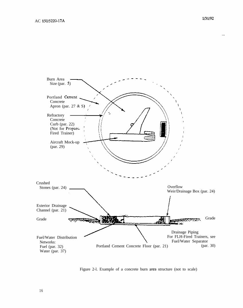
b. Building Material Alternatives. ThisAC specifies two building material alternatives forthe bum area structure. Section 2 describes theuse of concrete as the primary building materialas illustrated in figure 2 - 1. Section 3 describes
the use of flexible membrane liners as the primarybuilding material as illustrated in figure 2-2.Section 4 describes a bum area structure designedand suitable for the use of propane fuel.
C. Fuel Alternatives. This AC specifies theuse of either an appropriate FLH fuel or anappropriately controlled propane fueled system.The use of alternate fuel(s), as yet unspecified,which can be appropriately controlled to providethe simulated affect of the typical FLH fuel spillfire and/or the other required fire scenarios isacceptable.
Section 2. CONCRETE ALTERNATIVE FOR FLH
21. RIGID BURN AREA STRUCTURE.
a. Basic Design. The basic design consistsof a rigid floor and walls to retain fluids and asecondary means of containment to safeguard thegroundwater.
b. Design Service Temperature. Thedesign service temperature of the burn areastructure shall be 2,100” F (1,149” C).
C. Floor and Wall. The floor and wallsshall be of an air-entrained, reinforced portlandcement concrete in accordance with Paragraph 41,Cast-In-Place Concrete. Floors shall slope tochannel water towards interior drains for drainageand to simplify routine maintenance andstructural inspections. Interior drains shall befitted with a screen or a comparable device topreclude the migration of crushed stones into thedrain. A drain system shall be placed below thefloor to relieve the build up of hydraulicpressures beneath the burn area structure. If aperforated drain pipe is placed, it shall bewrapped in a geotextile fabric to preventmigration of foundation materials.
d. Protection from Heat.
(1) Protection for building materialsfrom the heat energies is provided by an overlyinglayer of crushed stones submerged in water. Theminimum depth of the crushed stone layer shallbe six inches (15 cm) taking into account thesloping floor. Crush stones shall be in
accordance with Paragraph 24, Interior CrushedStones for the Burn Area Structure.
(2) Materials for fabricating theexposed portion of the reinforced wall, i.e., thecurb, shall be in accordance with Paragraph 22,Refractory Concrete Curb for FLH-FiredTrainers.
22. REFRACTORY CONCRETE CURB FORFLH-FIRED TRAINERS. To attain safer servicetemperature ranges for exposed curbs, therebyreducing the hazards of explosive spalling,refractory concretes shall be specified in lieu ofportland cement concretes. Both pre-fabs andready field mixes, termed “castables,” adequatelyreceive and absorb the destructive forces ofthermal shock and flame impingement. Castablerefractories shall be in accordance withParagraph 42, Refractory Concrete. An addedbenefit in specifying pre-fabs sections is qualitycontrol in their manufacturing. Refractoryconcrete field mixes that require the addition ofaggregates, binder, and clean water shall not beallowed.
a. Perimeter Curb Height and Width. Thedifference in height between the top of any curband an adjoining walking surface shall not exceed8 inches (20 cm). The minimum width at the topof the curb shall be at least 6 inches (15 cm).These dimensions furnish fully clothed trainees anonhazardous footing when entering and exitingthe burn area structure under firefightingconditions.
15
AC 150/5220-17A l/31/92
-
Burn AreaSize (par.
-e--v_/ . .
Portland Cement -ConcreteApron (par. 27 Sr S)
RefractoryConcreteCurb (par. 22)(Not for Propant.Fired Trainer)
Aircraft Mock-up(par. 29)
\\
\\
\\
I
II
II
//
//
CrushedStones (par. 24) Overflow
Weir/Drainage Box (par. 24)
Exterior DrainageChannel (par. 21)
Grade Grade
Fuel/Water DistributionNetworks:Fuel (par. 32)Water (par. 37)
Drainage PipingFor FLH-Fired Trainers, see
Fuel/Water SeparatorPortland Cement Concrete Floor (par. 21) (par. 30)
Figure 2-l. Example of a concrete burn arca structure (not to scale)
16

- -
l/31/92 AC 150/5220-17A
b. Interior Separation Curbs. FLH-fired perimeter curb, for example at least 2 inchestrainers can reduce the quantities of training fuel (5 cm) lower but not more than 4 inches (10 cm).and water (that immerses the crushed stones) by Drainage of zonal areas can be performed byerecting interior separation curbs to permit drainage gates located below the top surface ofspecific zonal training. The height and width of the crushed stones. Drainage gates shall meet thesuch curbs shall comply with perimeter curb design service temperature of the burn areastandards. The curbs should be lower than the structure.
Section 3. FLH FLEXIBLE MEMBRANE LINER ALTERNATIVE
23. FLEXIBLE BURN AREA STRUCTURE. (2) Interior Drainage Flow Net. The
a. Basic Design. The basic design consistsof a sealed three layer system of two high densitypolyethylene (HDPE) flexible membrane liners(FML) separated by an interior drainage flow net(see figure 2-2). The system continues downwardand beyond the burn area structure to function asa collection system to accumulate, detect, andpermit removal of any leaked fluids. FMLsshould not to be used as a structural component.
interior drainage flow net separates the primaryand secondary HDPE FMLs to provide leakedfluids flow paths for detection at the monitoringwell. The design pattern of the net shall allowcollected fluids multi-directional flow paths to thedetection device. Flow nets shall end next to theperimeter of the sealed HDPE FMLs, i.e., belowthe berm. Interior drainage flow nets shall be inaccordance with Paragraph 45, Drainage FlowNet.
b. Design Service Temperature. Thedesign service temperature of the burn areastructure shall be 2,100“ F (1,149” C).
.-
C. Floor and Walls. The sloped floor andsloped walls shall be fabricated from two layers ofHPDE FMLs that are sealed (seamed) andseparated by a materially compatible interiordrainage flow net. The lowest point of thesystem shall be located outside of the burn areastructure where a monitoring well houses a leakdetection device, Side slopes shall follow theHDPE FML manufacturer’s recommendation forwall stability, generally 3:l. The three layersystem surrounding the burn area structure shallbe mechanically anchored below the berm andcovered with backfill material. Berm and backfillmaterial shall be in accordance withParagraph 25, Berm.
(3) Protection from Heat. Protectionfor building materials from heat is provided by anoverlying layer of sand and crushed stonessubmerged in water and an inner ring section(defined in paragraph 25(c)).
(i) Sand. A minimum of sixinches (15 cm) of sand followed by a minimum of12 inches (30 cm) of crushed stones shall beplaced immediately above the primary liner. Sandshall be of natural river, bank, or manufacturedsand, washed, free of silt, clay, loam, friable, orsoluble materials, and organic matter, graded inaccordance with American Society for Testing &Materials (ASTM) C 136, Standard Method forSieve Analysis of Fine and Coarse Aggregates,within the recommended limits of “FineAggregate” category of ASTM C 33, StandardSpecification for Concrete Aggregates (optionalparagraph 5.2 is acceptable).
(1) HDPE FML System. The upperHDPE FML functions as the primary holdingbasin of fluids while the lower secondary HDPEFML collects and channels leaked fluids fordetection. The secondary liner shall have theability to contain at least 100 percent of thevolume of the upper primary liner and be sealedto the primary liner. A geotextile fabric shall beplaced between the secondary liner andfoundation material to protect the liner fromfoundation material. HDPE FMLs shall be inaccordance with Paragraph 44, Flexible MembraneLiner.
(ii) Crushed Stones. Crushedstones shall be in accordance with paragraph 24.
(iii) Drains. The drainage systemabove the primary liner shall preclude themigration of sand and crushed stones, e.g., draincovers with filters, use of perforated drain pipes.Drain components subjected to FLHs shall havepositive sealed joints as compared to rubbergaskets. Polymer drain components (plastics)shall be compatible with FLHs.
17

AC 150/5220-17A l/31/92
-
OuterToe ~,-- ___-- ------------------.\\
\
Berm (par. 25) /’\\
1
I
I
I I
i I\ /
//
.’-__----------- __---- ------
Crushed Stones (par. 24)
3-Layer SecondaryContainment System:HDPE FML (par. 23),Drainage Net (par. 23)
Geotextile Filter FML Trench (par. 23)
Fuel/Water DistributionNetwork: Fuel (par. 32), Water (par. 37)
Figure 2-2. Example of a flexible membrane liner burn area structure (not to scale)
18

l/31/92
( 4 ) G e o t e x t i l e F i l t e r F a b r i c . A
L.--- geotextile filter fabric shall be placed directlyabove the sand layer to stop the intermingling ofcrushed stones with the underlying sand layer.The sand layer protects the primary liner frombeing punctured by intruding crushed stones andexploratory maintenance. The fabric shall endunder the inner ring section. Geotextile filterfabrics shall be in accordance with paragraph 46,Geotextile Filter Fabric.
d. FML Trench and Monitoring Well. AFML trench shall extend beyond the burn areastructure and slope continuously downward toaccommodate a monitoring well. The trench shalluse the same FML used for the burn areastructure. The monitoring well shall have a leakdetection device within a sump.
24. INTERIOR CRUSHED STONES FOR THEBURN AREA STRUCTURE. The crushed stones(or another medium known to be suitable for theintended service) placed within the burn areastructure function as a quick drainage medium,level walking surface, and a heat absorbent shield.For FLH-fired trainers, crushed stonesadditionally help to counteract the drifting of fuelby wind forces. The crushed stones shall beangular, well graded, and free of shale, clay,friable materials, and debris with a nominalmaximum aggregate size of 1 l/2 inches (3.8 cm)and a nominal minimum size of l/2 inch (1.3 cm).Standard size number 4 (four) of ASTM D 448,Standard Classification for Sizes of Aggregate forRoad and Bridge Construction and standard sizenumbers 4 (four) and 5 (five) of ASTM C 33 arepossibilities. Grading shall be in accordance withASTM C 136.
Aggregates, e.g., those containing quartz,NOTE:that are prone to fracture when theyexperience a large volume change attemperatures well below the designservice temperature should not bepermitted.
25. BERM.
a. Slope. The slope of the berm shallprovide a gentle, nonhazardous footing for fullyclothed trainees entering and exiting the burnarea structure under firefighting conditions. Toprovide such footing, slopes shall range from 4:lto 3:l (horizontal:vertical).
AC 150/5220-17A
b. Backfill Material. The backfill materialspecified shall be uniformly graded, free of friableor soluble materials, clay, loam, and silt, andother debris and shall contain a much higherpercentage of fines than the crushed stonesspecified in paragraph 24. The selected coveringmaterial should not cause the liner to bepunctured and have good erosion resistance.Table 2-l offers one possibility. The higherpercentage of fines serves to (1) provide aprotective heat absorbing blanket for the primaryliner, and (2) limit the fluid/water mixture’sdownward penetration into the inner toe of theberm by more readily conveying it towards thelower more porous crushed stone layer.
Sieve Size Percent Passingby Weight
2 inch 1001 inch 95-100
3/4 inch 80-1005/8 inch 75-1003/8 inch 50-85No. 4 35-60No. 10 22-50No. 16 15-35No. 40 15-30No. 200 5-10
Table 2-l. Example gradation of backfillmaterial for berm and adjoining inner ring section
C. Inner Ring Section. The Inner RingSection shall continue downward from the insidetoe of the berm for a maximum horizontal lengthof 9 feet (2.75 m). Besides being composed ofthe same backfill material and executing theabove dual functions, it marks for FLH-firedtrainers the upper level of the training fuel andwater sublayer mixture. Regardless of the fuelalternative, the backfill cover at the innermostpoint shall be a minimum of 18 inches (46 cm) toprotect the primary liner from heat.
19

AC 150/5220-17A l/31/92
26. PROPANE BURN AREA STRUCTURE.When compared to a FLH-fueled trainer, anappropriately controlled, propane-fueled systempermits significant simplification of the designrequirements of the burn area structure. Forexample, the lack of a water sublayer may reducethe size needed for water storage and thecomplexity of the distribution system. Also, someState Environmental authorities may not requirecertain of the protective measures needed toprevent ground water contamination. Whenappropriately controlled, the propane-firedsystems also greatly reduce air pollution problems.
a. Basic Design. The basic design for fixedsystems shall use either the rigid or the flexibleburn area structure alternatives discussed inSections 2 and 3. Modifications are permitted asmay be required by the unique properties andfunctions of the propane system design.
b. Design Service Temperature. Sincetotal exposure to heat is better controlled (ascompared to FLHs), construction materials usedin the burn area structure shall be materialsdemonstrated to withstand the exposuretemperature. For example, under the rigid
Section 4. PROPANE SYSTEM ALTERNATIVE
alternative refractory material for the curb is notrequired. Instead, curb material shall be concretemasonry block units or air-entrained portlandcement concrete with an f, = 3,000 psi .Selection of masonry units shall note NationalConcrete Masonry Association (NCMA) - TEKSTD 117, Evaluation of Concrete Masonry WallsAfter Being Subjected to Fire. Curb height andwidth standards of subparagraph 22(a) shall apply.
C. Floor and Wall. The floor and wallmaterials (non-curbs) shall be an air-entrainedportland cement concrete with an f, = 3,000 psithat is reinforced. Portland cement concrete shallbe in accordance with paragraph 41. Floors shallslope to channel water towards drains fordrainage and to simplify routine maintenance andstructural inspections. Drains shall be fitted witha screen or a comparable device to preclude themigration of crushed stones into the drain. Adrain system shall be placed below the floor torelieve the build up of hydraulic pressuresbeneath the burn area structure. If a perforateddrain pipe is placed, it shall be wrapped in ageotextile fabric to prevent migration offoundation materials.
Section 5. SUPPORT COMPONENTS FOR TRAINING FACILITIES
27. CONCRETE APRON.
a. Building Material. The apron shall bean air-entrained portland cement concrete. Thismaterial, compared to refractory concretes, isacceptable since temperature and energy radiantstresses are less severe than those experienced bythe curb. The compressive strength of theconcrete shall be adequate to support fully loadedARFF vehicles.
b. Slope. The concrete apron shall slopetowards the curb of the burn area structure tocollect training spills, rainfall, and snowmelts. Ifthe apron has a drainage channel adjacent to thecurb, the drainage channel shall be covered withdrain covers that withstand both bearing loadsand high temperatures. The transition jointbetween the upper portion of the concrete apronand the ARFF vehicle maneuvering surface shallbe as smooth as practical.
C. Length. The length of the concreteapron shall be 10 percent of the square root ofthe total square footage of the burn areastructure, but not less than 6 feet (1.8 m) ormore than 12 feet (3.7 m).
d. Thermal Treatments for PortlandCement Concrete Aprons. The following itemscan increase the thermal resistance ofASTM C 150 type portland cement concretes tolessen the frequency of concrete thermal spalling.
(1) Unit Weight. Lightweightconcretes, i.e., unit weights of 85 to 115 pcf (1360to 1840 kg/m3), offer greater thermal insulationthan normal or heavy weight concretes. As arule, a decrease in concrete unit weight results inincreased thermal insulation (i.e., lowerconductivity values). Structural lightweightaggregates should be in accordance withASTM C 330, Specification for LightweightAggregates for Structural Concrete.
20

l/31/92 AC 150/5220-17A
(2) Binder. Greater thermal resistance
b is possible by using calcium aluminate cements orbinders with increased Alumina, A&O,, and Silica,SiO, contents. Replacing aggregates with morecement binder also lowers thermal conductivityvalues.
(3) Aggregate Size. For normal weightconcretes of unit weights between 135 to 160 pcf(2 160 to 2 560 kg/m3), decreasing the maximumaggregate size increases thermal resistance.
(4) Free Moisture Content. Loweringthe free moisture content of hardened concreteincreases its thermal insulation by an associatedreduction in thermal conductivity values (smallerthermal expansions).
(5) Air Content. An increase in thepercentage of air content provides greaterinsulating values, particularly for air contentsabove 10 percent. Lightweight concretes achieveeven greater insulating improvements at thispercent air content compared to normal weightconcretes.
28. OVERFLOW WEIR/DRAINAGE BOX FORFLH FIRED TRAINERS. The top of the
- overflow weir(s) or drainage box should beslightly higher than the fuel level which is kept ator slightly below the protruding edges of thecrushed stone surface. Metal grates thatwithstand the design temperature should rest on“L” iron sections attached to a concrete vault.Collected flows shall have a drain pipe thatdirectly feeds the fuel/water separator system forrecycling. A gas-tight trap in the weir or betweenthe weir and the fuelhater separator shall beinstalled to avoid possible fuel vapor-airexplosions. Weir/drainage boxes may be attachedto or near the periphery of the burn areastructure.
29. AIRCRAFT MOCKUP. An aircraft mock-upshall be provided that can present thecomplications normally encountered in thesuppression of a variety of real exterior andinterior aircraft fires. Large pool fires and othertraining fire scenarios may be supported by eithera single multi-purpose training mock-up or a pairof mock-ups.
The mock-up shall have strategically located firedevices and other special features to simulate thevariety of mandatory aircraft fires described inparagraphs 29c(l)-(3). Figure 2-3 illustrates anexample of a single wing, truncated mock-up withan elliptical cross section and FLH fuel nozzle orpropane-fired gas burner element locations.
b. Split Function Mockups. If thisalternative approach is selected, two mockupsshall be provided that will permit the separationof the large pool fires from the other training firescenarios. The major aircraft fuel spill simulatorshall be located within the burn area structure ina manner similar to that shown in figure 2-l.The other mockup shall contain all of the othermandatory fire scenarios that cannot beaccommodated by the major spill fire simulator.It may be located in any convenient place withinthe training ground that is compatible with theoverall training area layout and may beportable/mobile.
C. Mandatory Fire Scenarios.
(1) Class A F i r e s . Baggagecompartment and interior cabin fires, such asgalleys, cockpit, lavatory, trash containers, thatcan be accessed through replaceable “forced entry”exterior panels or doors and landing gear,brakebheel fires by an under-the-wing “landinggear” device. For the simulator using FLHs, astock of class A combustibles will be required to“refit” the mock-up for cabin and cargo trainingscenarios. Where this class of fire scenario isbeing provided by a propane-fired simulator, thereis no requirement for a stock of Class A fireconsumables.
(2) Class B Fires. Large pool fires,engine nacelle fires, and ruptured wing fuel fires.The last two shall provide cascading or 3-dimensional fire training exercises.
(3) Other. For safety reasons, Class C(energized electrical) and Class D (combustiblemetal) fires, shall not be part of the FLH-firedmockup. Separate “stand alone” ftiures will beneeded for these scenarios. Simulated Class Cand D fire scenarios shall be provided as anintegral part of the propane-fired mock-up.
a. Single Mockup Model. The mock-upshall be located within the burn area structure ina manner similar to that shown in figure 2-l.
21

AC 150/5220-17A l/31/92
h
WindDirecticn
-
WindDirection
View A. View B.
x= fuel nozzle or propane burner element location
A. Galley/Cockpit/Lav/Trash ContainersB. Engine Nacelle Mock-UpC. Landing Gear Brake/Tires Mock-UpD. 3-Dimensional Fuel FiresE. Underwing DifficultiesF. Replaceable "Forced Entry" Panels
Figure 2-3. Example of an aircraft mock-up
d. Orientation. As is shown in figure 2-4,any fixed mock-up located within the burn areastructure, shall be orientated with its axis directedtowards the control center and the prevailingwinds.
e. Shape and Exterior Materials. Theshape of the mock-up shall generally represent anaircraft. For example, the fuselage may take theshape of a long narrow building with verticalwalls, circular windows, and an arched roof.Selected materials shall be those with the abilityto withstand high radiant energies, direct flameimpingement, and repeated thermal cyclingstresses. Figure 2-4, reprinted from NFPA 422M,Aircraft Fire and Explosion Investigation, providesthermal performance of metals, such as iron, tofabricate the fuselage and wing. Exteriormaterials other than metal that meet the designservice temperature such as those found in firetraining towers are also acceptable. Precautionsshould be taken to exclude air pollutantgenerating materials such as plastics (polyurethanecan form HCN) and rubber tires.
f. Sizing. The primary consideration forthe size and shape of the aircraft fuselage mock-up is to provide a viable target for practicingaircraft rescue and firefighting operations. Hence,maintaining a reasonably realistic cross sectionand using a somewhat truncated length generallyfulfills the functional requirements of a mockup.The mock-up structure for ARFF trainingfacilities using either a controlled, propane-fired,or a FLH-fired simulator shall have at least twodoorways on each side for rescue training. Thefuselage floor in all mock-ups intended forinterior aircraft firefighting operations shall becapable of supporting the loads imposed bytrainees during rescue and interior firefightingexercises. The mock-up shall be sized as follows:
(1) Length. For ARFF index A and Bsimulation, the fuselage mock-up shall be at least50 feet (15.25 m) long. For ARFF index Cthrough E simulation, the fuselage mock-up shallbe at least 75 feet (23 m) long. If the mock-upis to be a mobil unit, the length of the longestcomponent shall be no longer/heaver than thatwhich meets the legal length/axle weighttransportability requirements for public highwaytransportation.
22

lL31P2 AC 150/5220-17A
Tungsten melts (6,170 "F)
Molybdenum melts (4,760 "F)---------r
3500
Chromium melts ---- - - - - - -
Vanadium melts --------+'
Titanium melts d3000
Iron melts
Stainless steel meltsNickel meltsSilicon melts
2500
Brass melts (1,600-2,000 "F)
Copper melts12000 -
S i l v e r m e l t s - - -
Glass softens (1,400-1,600 “F)
1500 -Silver solders melt (1,165-1,450 OF)-
Magnesium meltsGlass cloth fusesAluminum alloys melt
1000 -Aluminum becomes plastic, sags--, -
Zinc melts
Lead meltsCadmium melts
500 -
-l-z- --711t1 lllelts
Silicon rubberSelenium meltsCellulose distPhenolics delaPolystyrene diPlastic vinyl chloride distorts
0 "F -
t
-INormal range
for
infliehtfires (forced
draft effect)
FLH Design geE&creFTemperaturef
-Burns off
-I
Normal rangefor ground
fires (fuel,
oil, hydraulicfluid)
\ --Black' Blisters 4
DiscolorsDTrk Brown
IBrown
7Softens I-Tan
I IAircraft Paints Zinc
;lxittte
Figure 2-4. Metal material selection guide for mock-ups (reprint fromm
23

AC 150/5220-17A l/31/92
(2) Height and Width. The fuselagediameter shall be at least 10 feet (3.0 m) formock-ups with round cross sections. Ifrectangular, it shall be at least 7 feet (2.1 m) wideby 7 feet (2.1 m) high.
(3) Wing Span. The wing span for theSO-foot (15.25 m) long mock-up shall at least25 feet (7.5 m) from the fuselage centerline tothe wingtip. For the 75-foot (23 m) long mock-up, the wing span shall be at least 30 feet (9 m).The spacing of wing support columns shouldevenly distribute the weight on spread footings toeliminate damage to the concrete or HDPE Fh4Lfloor. Additional geotextile fabric placed over theprimary liner may be necessary to providerequired protection in FLH-fired facilities.
h. Placement of Fuel Nozzles, PropaneBurner Elements, and Water Nozzles. Placementof fuel nozzles or propane burner elements shallbe based on the specific type of fire to besimulated (see figure 2-3). Nozzles or elementslocated adjacent to the mock-up shall be evenlyspaced around its exterior wall. To increase themock-up’s service life, provisions for internalwater spray, water drains at all low points, and airvents on the sides and top of the mock-up’s mainbody, wing(s) and, if present, the tail section shallbe provided. The air vent pattern shall provideadequate openings in conjunction withappropriate spacing to prevent the build up of anexplosive fuel-air mixture within the mock-upitself.
!z* Tail Section. The mock-up may includea tail section with or without an engine pod. Ifinstalled, the dimension of the tail sections shallbe in approximate proportion to the basicmockup.
i. Fuel Ignition. A means of fuel ignitionshall be employed that is effective under allnormal weather and operational conditions andcan reliably ignite all nozzles or elements selectedby the instructor for a given exercise.
-
Section 6. SUPPORT SYSTEMS
30. FUEL/WATER SEPARATOR FOR FLHFIRED TRAINERS. FLH fuel trainers shall havea fuel/water separator to recycle fuel and waterquantities for setup and those resulting fromtraining. Besides the financial savings achievedthrough recycling, the additional cost for frequentdisposal of contaminated FLHs and water iseliminated.
a. Pump Design. The fuelhater separatorshall be equipped with an explosion-proof pump.
b. Separator Capacity. The capacity shallhandle the total quantity of fluids collected fromat least two training sessions, plus ten percent.Depending on operating permits, extra capacityfor captured rainfalls and snow melts may need tobe provided. For facilities where high volume orfrequent use is anticipated, the separator capacityshall be sized to accommodate the anticipated uselevel, plus ten percent.
C. Secondary Containment. The separatorshall have a secondary means of containment, forexample, a flexible membrane liner.
31. CONTROL CENTER BUILDING ANDPROTECTIVE WALL.
a. FLH-Bred Trainer. This trainer shallhave only a protective wall with a viewing windowto provide an instructor or safety officer acomplete visual view of the burn area structurefor monitoring training exercises (see figure 2-5).Additionally, the wall can provide protection toother training facility items such as, fuel andwater storage tanks. The protective wall shall:
(1) Be at least 150 feet (46 m) upwindwith respect to the prevailing winds to alleviateblinding smoke and fire hazards caused bywandering gas vapors. Generally, the direction ofprevailing winds is identical to the airport’s windrose. However, a different wind orientation ispossible. For example, an airport may have alimited training season because of severe wintersor heavy seasonal rainfalls. Under theserestrictions, a different seasonal wind orientationmay exist.
(2) Have a viewing window next to thecontrol console to monitor training exercises.
24

l/31/92 AC 150/5220-17A
-
Burn Area Structure
Protective Wall withControl Panel andViewing Window
Fuel/WaterSupply/Return Piping
l/d
’ \/‘a% \-/ \
Water Tank , II .I1L-.
Fuel Tank with Dike
‘loFigure 2-5. Example location of a control center
(3) Have a height equal to the heightof the tallest aboveground fuel tank but not over8 feet (2.4 m) and, if used to protect a fuel tank,a width not less than 15 feet (4.6 m).
(3) If the propane-fired mobile mock-up option is used, the control center may be anintegral part of the overall unit.
b. Propane-fired Trainer. This trainershall have an environmentally regulated, i.e.,HVAC, control center building or area to housethe equipment (computer, printer, controls, andetc.) and supporting hardware needed to regulatefire simulations and record training exercises.The control center shall provide an instructor orsafety officer a complete visual view of the burnarea structure for monitoring training exercises.The control center shall be:
C. Building Housing Propane Containers.Though a separate building is not required tohouse LP-gas containers, the construction andventilation of such a structure shall be inaccordance with NFPA 58, Standards for theStorage and Handling of Liquefied PetroleumGases.
32. FUEL DISTRIBUTION SYSTEM FOR FLHS.
(1) Located at least 150 feet (46 m)upwind with respect to the prevailing winds fromthe burn area structure to alleviate smoke andflame impingement. However, a differentor ienta t ion i s poss ib le as n o t e d i nparagraph 31a(l).
a. Basic Design. The system consists ofthe fuel storage tank(s), metered supply pipingsystem, explosion-proof pump(s), meteredindependent zonal fuel delivery network, and theburn area fuel delivery network (see figures 2-5and 2-6).
(2) Equipped with the necessarycomputer hardware or other appropriate means toperform varying degrees and types of trainingexercises and a hard copy printer or otherappropriate means to record training performanceand provide permanent reports.
b. Emergency Shutoff System. Each fueldistribution system shall have an emergencyshutoff system to quickly and completely stop theflow of fuel in an emergency. Operating controlsfor emergency shutoff shall be located so as to bereadily and safely accessible in the event of anemergency or spill. Location and placarding ofshutoff devices shall conform to NFPA 407,Aircraft Fuel Servicing.
PrevailingWinds
Fuel/water Separator
25

AC 150/5220-17A l/31/92
C. General Tank Requirements. d. Pumps.
(1) Capacity. Tank capacity shall atleast equal the sum of the fuel quantities for (a)two successive burns, which may be based onfigures l-4 through l-7, (b) the volume of thesupply piping system, and (c) fuel quantitiesrequired to maintain the design discharge rateand duration for all systems operatingsimultaneously.
(2) Tank Fill Cap. The tank’s fill capshall be protected by either a recessed vault orhave painted barrier posts. For security, fill capsshall have locking capability.
(3) Fuel Transferring Protection. Anadequate means for static electrical dischargeprotection during fuel transfer shall be installed.For guidance see NFPA 407.
(1) Type. All pumps shall be anexplosion-proof/weatherproof, electrically drivenmotor design and type that deliver the designdischarge flow rate. The design discharge flowrate shall consider the hazardous generation ofstatic electricity that accompanies fuel transfer.Rapid transferring of fuel causes the fuel to beelectrostatically charged. If the charge on the fuelis sufficiently high upon being sprayed by thenozzles, a static spark could occur and pre-maturely ignite the flammable mists and vapors.However, a reasonable delivery time is sought topreclude explosion or fire hazards (flammable fuelatmosphere inside and outside the burn areastructure if ignition is delayed) and forenvironmental reasons (poisonous vapors).
V e n t ?lpeOprnina
toIndependentZone1 DeliveryWe cuork
ControlShutoffVdvr
Dy-prar Linr 1
Irolrtion Valvr
WeLn D r a i n LCollrcrion Berln
Indrprndrrc
Sane1 DellvevNetwork
Figure 2-6. Example of an FL,H storage tank, pump, supplypiping, and independent zonal delivery network
26

l/31/92
(2) Instal lat ion. Pumps installedoutside of a shelter shall be located not less thanfive feet (1.5 m) from any building opening.Pumps installed in a building shall be in aseparate room with no opening into otherportions of the building. The pump room shallbe adequately ventilated to prevent explosivevapors from collecting and posing an explosive orfire hazard. Pumps shall be adequately anchoredand protected against physical damage.
33. UNDERGROUND STORAGE TANK (UST)FOR FLHS. The installed UST shall be inaccordance with 40 CFR Part 280. Theseregulations concern proper installation, spill andoverfill prevention, corrosion protection, and leakdetection. It is important to remember that theseregulations apply to the entire UST system, thatis both the tanks and underground piping.
a. Spill and Overfill Prevention. Many ofthe leaks at USTs are actually the result of spilland overfill errors, two separate problems.Athough new USTs must be equipped with bothspill and overfill protection prevention devices,transfer of fuel should be constantly observed.Fuel transfer practices are found in AC 150/5230-4, Aircraft Fuel Storage, Handling, andDispensing on Airports, API Publication 1621,Recommended Practices for Bulk Liquid StockControl at Retail Outlets, NFPA 30, Flammableand Combustible Liquids Code, and NFPA 385,Standard for Tank Vehicles for Flammable andCombustible Liquids.”
b. Burial Depth and Cover for USTs.
(1) Steel Tanks. Section 2 ofappendix 1 provides standard engineeringinstallation practices related to adequate firmfoundations, anchorage and buoyancyrequirements, noncorrosive inert blanketmaterials, etc. The depth of cover placed over atank is dependent upon whether the tank will orwill not be subjected to vehicle traffic.Installation practices shall be in accordance withAPI Publication 1615-79, Installation ofUnderground Petroleum Storage Systems, orNFPA 30 unless otherwise directed by theengineer.
AC 150/5220-17A
(2) Non-Metallic Tanks. Theinstallation shall follow manufacturer’s instructionwith the minimum cover as specified for steeltanks unless otherwise directed by the engineer.
C. Tank Placement. Tank placement shallbe at a distance that protects the tank from the“radiant” heat loads generated by the burn areastructure.
34. ABOVEGROUND STORAGE TANKS FORFLHS. An aboveground storage tank with aminimum capacity of 1,100 gallons is defined byUSEPA as an underground storage tank (UST)when its below ground storage capacity is10 percent or more, including undergroundpiping.
a. Overfill Prevention. Since fueltransferring errors cause most spills and overfills,it is recommended that aboveground tanks, eventhough not required by EPA, have UST overfillprevention.
b. Dike Designs. A dike shall be providedfor each aboveground tank to prevent theaccidental discharge of fuel from endangeringother facility components, adjoining property, thegroundwater, or a waterway.
(1) Capacity. The capacity of the dikeshall equal the sum of the total tank volume andthe volume displaced by the tank that is belowthe height of the dike.
(2) Walls and Floor. Material for thewalls and floor shall be of reinforced concrete,solid masonry, or a combination. Walls shall beliquid tight under a full applied hydrostatic head.Normal wall height above the interior dike floorshould be less than six feet (1.8 m). If a dikewall is greater than six feet (1.8 m), the wall shallhave special provisions for normal and emergencyingress and egress.
(3) Subdivided Dikes. Dikes that housetwo or more fuel tanks shall contain anintermediate curb to form individual dikes.
27

AC 150/5220-17A
(4) FLH Fuel Resistant Concrete JointSealer. One of the following FLH-fuel-resistantconcrete joint sealers shall be specified: (1)ASTM D 1854, FLH-Fuel-Resistant ConcreteJoint Sealer, Hot-Poured Elastic Type, (2)ASTM D 3569, Joint Sealant, Hot-Applied,Elastomeric, FLH-Fuel-Resistant-Type forPortland Cement Concrete Pavements, (3)ASTM D 3581, Joint Sealant, Hot-Poured, FLH-Fuel-Resistant Type, for Portland CementConcrete and Tar-Concrete Pavements, or (4)Federal Specification ss-s-200, SealingCompounds, Two-Component, Elastomeric,Polymer Type, FLH-Fuel-Resistant, Cold Applied.
(5) Penetrating Pipes. Pipes passingthrough a dike shall be designed to preventexcessive stress and leaks as a result of settlementor fire damage.
C. Support, Foundations, and Anchorage.The design of tank supports and connections inareas subjected to earthquakes shall be inaccordance with Appendix E of API Standard650, Welded Steel Tanks for Oil Storage,Appendix B of API Standard 620, Rules forDesign and Construction of Large, Welded, LowPressure Storage Tanks, or the jurisdiction havingauthority.
lMlP2
35. DESIGN OF SUPPLY PIPING SYSTEMFOR FLHS. The metered fuel supply pipingsystem, regardless if it is part of an UST systemor not, shall be in accordance with 40 CFRPart 280. These regulations concern properinstallation, corrosion protection, and leakdetection. The design of the piping system shallmeet the mechanical and thermal stresses and theworking pressure that are capable of maintainingthe fuel discharge at the design rate for all zonesoperating simultaneously.
a. Design of Independent Zonal FuelDelivery Network. Each fire zone delivery pipeshall have a meter, pressure gauge, and controlvalve to regulate the flow within the burn areastructure. Zonal control valves shall be locatedfor easy emergency access. For protection, thezonal delivery network shall be placed belowgrade.
b. Design of Burn Area Structure FuelDelivery Network. Upon entrance, each zonaldelivery pipe may feed, via a distribution header,into supported branch pipes (risers) with thepredetermined number of fuel nozzles (seefigure 2-7). Supports for risers shall be of heat
-
Figure 2-7. Example of a fuel/water delivery network with four independent delivery zones
28

l/31/92 AC 150/5220-17A
- -
resistant materials. Each nozzle riser shall besupported below and plumbed for uniform fueldelivery. Correct placement of the nozzle headsis above the crushed stone surface with eachnozzle having several horizontal dischargeopenings. The maximum height of a nozzleprotruding above the crushed stone surface shallnot exceed 3 inches (7.6 cm). Nozzle coverageshould consider nozzle discharge characteristicsand its particular objective. Care shall be takenin positioning nozzles so that sprayed fuel doesnot fall outside the burn area structure.
to evaluate the effectiveness of the applied agent’spattern. Gathered information shall then betransmitted to the computer for controlling firepropagation via flow control valves, e.g., to reducefuel flow and cause the fire to recede andextinguish.
(2) Another means may be used toprovide the simulator operator with the feedbacknecessary to reliably assess student agentapplication performance if it can be shown thatthe resulting simulator performance provides safe,realistic, and repeatable training scenarios.
C. Identification. All exposed fuelelements and components outside the burn areastructure shall be painted and identified accordingto applicable codes or standards.
36. DESIGN OF COMPUTER CONTROLLEDDISTRIBUTION SYSTEM FOR LIQUIDPROPANE (LP). An LP-Gas distribution systemconsists of one or more containers with a meansfor conveying LP-Gas from the containers to thetrainer’s fire generation control system which shallinterface with agent application detectors andcomponents intended to achieve control ofquantity, flow, pressure, or state (either liquid orvapor). The LP-Gas system described shall notuse oxygen or contain ammonia.
. Fire Generation System. T h e firegene;ation system for the fuel spill fire shallconsist of a network of main flame burnerelements arranged throughout the fuel spill fireburn area, and a number of burner controlmodules that will control the flow of propane tothe burner elements.
a. Control System.
(1) A computer (or other appropriatemeans capable of providing the required firesimulation performance) shall regulate the flowof LP-Gas to burner elements based oninformation received from agent application,radiant energy, heat output, or other appropriatedetectors that evaluate the appropriateness of thepattern of applied agent and activate a series ofcontrol valves that control propane flow to thetrainer’s burn area.
(1) Burner Elements. The network ofburner elements shall be arranged across the fuelspill fire burn area so that each element willdistribute propane to a segment of the total area.The arrangement shall be such that control ofpropane flow to each element shall produce aflame that will realistically grow and spread acrossthe burn area, and then realistically recede andextinguish as the propane flow is manipulated inresponse to the appropriate agent application.Each element shall be arranged along the surface,or below the surface so as to be protected by thecrushed stone. The elements shall be designedand supported to prevent their movement ordamage by normal operation of the trainer. Ifabove the surface, their maximum height is3 inches (7.6 cm).
(2) The control system (computer orother appropriate device) shall be located in anenvironmentally controlled (HVAC) building/area(Control Center). The console housing thecomputer shall also include a color monitor andalphanumeric keyboard. A printer to recordtrainee performance shall complete the system.
b. Detectors.
(1) Agent application detectors shall belocated in an array within the burn area structure
(2) Burner Control Module. Eachburner control module shall provide an ignitionsource, e.g., a pilot flame, to ignite a portion ofthe fuel spill fire, a safety shutoff valve that willstop all flow of propane to the elements underthat module’s control in an emergency or uponloss of electrical power, and a series of controlvalves that will modulate propane flow toindividual burner elements. All burner controlmodules shall be operable from the firegeneration control center and shall reliablycontrol propane flow to individual burnerelements according to preset/predeterminedparameters that are realistically related to theprogress of the extinguishment effort.
29

AC 150/5220-17A ll31P2
d. Containers. Containers shall bedesigned, fabricated, tested, and marked (stamped)in accordance with the (1) Regulations of theU.S. Department of Transportation, the “Rulesfor the Construction of Unfired Pressure Vessels,”Section VIII, Division 1, (2) ASME, “Boiler andPressure Vessel Code”, or (3) the API-ASME‘Code for Untired Pressure Vessels for PetroleumLiquids and Gases” applicable at the date ofmanufacture.
(1 ) Conta iner Appurtenances .Fabrication and performance provisions shall bein accordance with NFPA 58. Containerappurtenances include pressure relief, connectionsfor flow control (filling, withdrawal, equalizing),liquid level gauging devices, and pressure gauges.
(2) Container Markings. Containersshall be marked as provided in the Regulations,Rules, or Code under which they are fabricated orin accordance with chapter 2 of NFPA 58.
(3) Location of Containers. Containersshall be located in accordance with chapter 3 ofNFPA 58.
e. Piping and Piping Systems. The systemshall have pipe, tubing, hose, and flexible rubberor metallic hose connectors and other valves andfittings as required to safely convey LP-gas ineither the liquid or vapor state at variouspressures from point to point.
f. Buildings or Structures Housing LP-GasDistribution Facilities. LP-Gas distributionfacilities that are housed in separate buildingsused exclusively for the purpose or in roomsattached to, or located within, buildings used forother purposes, shall be in accordance withChapter 7 of NFPA 58. This chapter covers theconstruction, ventilation and heating of structureshousing LP-Gas systems referenced in NFPA 58.
37. WATER DISTRIBUTION SYSTEM FORFLH-FIRED TRAINERS. The system consists ofa water storage tank(s), metered supply pipingsystem, water pump(s), independent zonal deliverynetwork and the mock-up water spray network(see figures 2-6 and 2-7).
NOTE: For propane-fired systems, a water spraycooling system utilizing local utility _-water supply pressure may be requiredif the mockup structure is not designedto withstand the heat and thermalcycling of the fuel spill fire.
a. Design of Water Storage Tanks.
(1) Materials and Fabrication. Thestorage tank shall be designed and built inaccordance with recognized engineering standardsfor the materials being used. Some industrystandards are American Water Works Association(AWWA) D 100-84, Welded Steel Tanks forWater Storage, AWWA D 103-80, Factory-CoatedBolted Steel Tanks for Water Storage, andAWWA D 120-84, Thermosetting Fiberglass-Reinforced Plastic Tanks.
(2) Tank Capacity. The tank capacityshall be based on the sum of either the watersublayer for FLH-fired training facilities for twosuccessive burns or operational quantities requiredfor a propane-fired training facility, plus thevolume of the supply piping system, the requiredwater flow rate and pressure to maintain thedesign discharge rate and duration for all systemsoperating simultaneously, flushing operations(repeated exercises) and, if included, thecontinuous mock-up water spray treatment.
( 3 ) S u p p o r t , F o u n d a t i o n s , a n dAnchorage. The design of tank supports andconnections in areas subjected to earthquakesshall be in accordance with Appendix E of APIStandard 650 or Appendix B of APIStandard 620.
(4) Identification. Aboveground tanksshall have the phrase “CONTAMINATED WATER”printed on both longitudinal sides. Letteringshall be at least one-foot (30 cm) in height andof a contrasting color.
b. Design of Metered Water Piping System.The metered water piping system shall bestructurally designed to safely accommodate theflow rate and fluid pressure needed to maintainproper water discharge levels at all zonesoperating simultaneously. Other designrequirements and recommendations are citedbelow.
30
l/31/92 AC 150/5220-17A
(1) Corrosion Protection. Systemcomponents installed in the presence of a
L corrosive environment shall be of corrosionresistent materials or be covered with protectivecoatings.
(2) Identification. For identification,all exposed water system components outside theburn area structure should be painted inaccordance with applicable codes or standards.
C. Water Pump. The water pump shall besized to meet the water discharge rates for (1) allspray nozzles operating simultaneously, (2) thewater sublayer, (3) the continuous mock-up waterspray treatment, if necessary, and (4) the burnarea flushing/turn-around time for FLH-firedtrainers. The water pump shall be of anexplosion proof type when it is housed adjacentto a fuel pump.
d. Design of Independent Water ZonalDelivery Network. Each independent zonaldelivery pipe shall have a control valve with apressure gauge to regulate the water flow withinthe burn area. Placement of the zonal controlvalve shall provide quick and easy access. Placingzonal delivery networks below grade offers pipingnetworks improved protection.
e. Design of Water Spray Network. Uponentrance to the burn area structure, each zonaldelivery pipe should feed, via a distributionheader, branch pipes (risers) having thedetermined number of water spray nozzles (seefigure 2-7). The maximum height of any nozzleprotruding above the crushed stone surface shallbe 3 inches (7.6 cm). The number of requirednozzles shall be based on the nozzle’s dischargecharacteristics and the particular function to beachieved. Care should be taken in positioningnozzles that water spray does not miss the targetsurface. Each nozzle riser shall be supportedfrom below and plumbed for uniform waterdelivery. Supports shall be heat resistant.
38. - 39. RESERVED.
31 (and 32)

l/31/92 AC 150/5220-17A
CHAPTER 3. CONSTRUCTION PHASE
40. STRUCTURAL STEEL.
a. Material Acceptance and Storage. Allreinforcing structural steel, including metalaccessories necessary for placing, spacing,supporting and fastening reinforcement, shallconform to the levels of quality specified toperform the functions intended. Upon delivery,these items shall be checked for conformance tospecifications and then properly stored from dirt,grease, and the environment.
b. Practices. All steel design, fabrication,and erection shall be in accordance with theAmerican Institute of Steel Construction (AISC),Specification for Design, Fabrication, andErection of Structural Steel for Buildings, andwith the AISC, Code of Standard Practice forSteel Buildings and Bridges, unless otherwisedirected by the engineer.
(1) Steel Reinforcing Bars and WeldedWire Fabric. Tolerances and placement forreinforcing bars, welded wire fabric, and metaldevices necessary for placing, spacing, supporting,
- and fastening reinforcement shall conform to theAmerican Concrete Institute (ACI) 318-83,Building Code Requirements for ReinforcedConcrete. For corrosion protection of rebars,protective coatings such as epoxy coatings arerecommended. If specified, they shall be inaccordance with ASTM A 775, Specification forEpoxy-Coated Reinforcing Steel Bars.
(2) Welding. Welding practices shallbe in accordance with AWS D 1.1, StructuralWelding Code - Steel, and appropriate AISCwelding specifications, unless otherwise directedby the engineer. Welders shall be qualified inaccordance with AWS D 1.1, Structural WeldingCode - Steel.
41. CAST-IN-PLACE CONCRETE.
a. Material Acceptance. Portland cementconcrete shall be mixed and delivered inaccordance with ASTM C 94, StandardSpecification for Ready-Mixed Concrete. Cementshall be ‘Qpe I (normal), II (exposure to sulfatebearing soils and seawater ), or III ( high early
strength) portland cements in accordance withASTM C 150, Specification for Portland Cement.The minimum Z&day compressive strength shallbe 4,000 psi for FLH concrete retainingstructures, e.g., burn area structure, concretefuel/water separator vaults (not the apron ordike) and 3,000 psi for propane-fired trainers.Upon placement, concrete shall have a slump of1 to 4 inches (AC1 211) and percent air (+ 1%)in accordance with paragraph 4.5.1 of AC1 318.
b. Practices. Concrete design shall be inaccordance with AC1 318 unless otherwisedirected by the engineer. Regions subject tomoderate or high seismic risks shall noteAppendix A, Special Provisions for SeismicDesign, of AC1 318. Hot weather and coldweather concreting practices shall be inaccordance with AC1 305R, Hot WeatherConcreting and AC1 306R, Cold WeatherConcreting. Special emphases shall be observedduring (1) placement of concrete, i.e., concreteshall be deposited continuously in layers of suchthickness that no concrete will be deposited onconcrete which has hardened sufficiently to causeseams or planes of weakness, and (2) curing ofconcrete, i.e., controlled curing is one of the bestprecautions to make concrete watertight.
C. Clean Water. Water shall be clean,potable, and free from pronounced odor.
d. Aggregates. The nominal maximumaggregate size shall be 3/4 inch in accordance withASTM C 33 (e.g., coarse aggregate size number67). The material shall be free of injuriousamounts of shale, alkali, organic matter, loam, orother deleterious substances. Paragraph 5.3.2 ofAC1 211 shall be observed, e.g., in no event shallthe nominal maximum size exceed 1/5th of thenarrowest dimension between sides of forms.
e. Admixtures. Air-entrained admixturesshall comply with ASTM C 260, StandardSpecification for Air-Entraining Admixtures forConcrete. Calcium chloride shall not be used asan admixture. All other chemical admixtures andmineral admixtures shall meet the appropriatestandard specifications set forth by ASTM.
33

AC 150/5220-17A Km92
f. Non-Shrink Grout. Grout shall be anon-shrink grout in accordance with U.S. ArmyCorps of Engineers CRD-C-621, Handbook forConcrete and Cement, Specification for Non-Shrink Grout unless otherwise specified by theengineer.
g. Surface Finish. Surface finishing shallproceed only after surface water has disappearedand concrete has set sufficiently to support theweight of workers and equipment. The surfaceshall dry naturally, e.g., do not dust surface withdry cement or sand. A power-driven floatmachine shall be used to float the surface of theburn area floor to produce a finish true toelevations and slopes with a uniform granulartexture. Hand floats shall be used in areasinaccessible to power-driven floats. Surfaces shallbe leveled to within l/4 inch in lo-foot in alldirections unless otherwise specified by theengineer. Concrete aprons and other walkingsurfaces shall be broomed with a flexible bristlebroom to produce a non-slip texture in adirection transverse to that of traffic or at rightangles to the slope of the surface.
h. C e m e n t i t i o u s Waterproof ing .Cementitious waterproofing shall be provided onthe “positive” inside surfaces of FLH fuel concreteretaining structures. Materials used forwaterproofing shall follow manufacturer’sapplication instructions to ensure properpenetration and closure of concrete capillarytracts. The selected cementitious waterproofingsystem shall become permanent and be non-toxic,inorganic, free of calcium chloride and sodiumbased compounds.
i. Fuel Resistant Concrete Joint Sealant.For FLH-fired trainers, the engineer shall specifyone of the following fuel-resistant concrete jointsealant: (1) ASTM D 1854, (2) ASTM D 3569,(3) ASTM D 3581, or (4) Federal Specificationss-s-200.
42. REFRACTORY CONCRETE.
a. Material Acceptance. Castablerefractory concretes shall be a class B or C(regular, not an insulating type castable) inaccordance with ASTM C 401, StandardClassification of Castable Refractories. Additionalrequirements may be specified by themanufacturer to offset the rapid heating and
cooling stress cycle, e.g., fast-fire variety castableto offset explosive spalling.
-
b. Practices. All construction practices andmaterials for placement, anchorage, finishing,curing, drying, firing of refractory castableconcrete shall be as specified by the refractorymanufacturer. Since refractories behavedifferently when compared to portland cementconcretes, contractor shall have prior constructionexperience with the product or be properlysupervised by the refractory manufacturer.
43. ELECTRICAL SYSTEMS. Electrical systems,equipment, wiring installation, and testing shallcomply with latest revisions of NFPA 70, NationalElectrical Code (NEC), and other applicable Stateand local regulations. Where codes and/orstandards conflict, the more stringent shall apply.
44. FLEXIBLE MEMBRANE LINER.
a. Material Acceptance. The liner shall bea high-density polyethylene (HDPE) flexiblemembrane liner (FML) of a non-extractableplasticizer quality certified by the NationalSanitation Foundation (NSF), or equivalent. Itshall:
(1) Have a minimum nominal gaugethickness of 80 mils (0.080 inch).
(2) Meet the material propertystandards for 80-mils noted in table 4,paragraph 3.1, including applicable annexes, ofNSF Standard #54, Flexible Membrane Liners,1991 edition.
(3) Meet the material compatibilitytests of the USEPA Test 9090 for the fuels andfire fighting foams used in training. If thesolution is not homogenous, i.e., consists of morethan one phase, then tests should evaluate eachphase.
(4) Be chemically compatible andappropriate for site specific considerations ascovered in annexes C and D of NSF 54.Considerations include moist environments,supporting soil environments, constant stressunder load at both normal and elevatedtemperatures.
34

l/31/92
( 5 ) N o t e x c e e d t h e m a x i m u mpermeability rate for FLH fuel established by the
-.--- applicable State (e.g., State Department ofNatural Resources) or local authority.Permeability tests may be in accordance withASTM E 96, Standard Test Method for WaterVapor Transmission of Materials, performed withthe type of hydrocarbon fuel to be contained.
(6) Have a high temperature resistanceof 240” F (116“ C) without performance failure.
(7) Have a high resistance to abrasion,humidity, rot, mildew, vermin, bacterialdeterioration, and sunlight (UV).
b. Bonded Seams. The seam is a criticalpart of the FML system. Seams may be eitherfactory or field constructed in accordance withannexes C and D of NSF Standard 54, 1991edition, for site specificity and chemicalcompatibility.
(1) Factory and field seamingtechniques shall be as listed in paragraph 4.2.1 ofNSF 54.
(2) Factory seams shall meet the- 80 mil physical property requirements of table 4,
paragraph 3.1 of NSF Standard #54.
(3) Field seams shall be in accoradncewith ASTM D 4437, Standard Practice forDetermining the Integrity of Field Seams Used inJoining Flexible Polymetric Sheet Geomembranes,for determining the integrity of field seams.
(4) Field seaming and repairs shall bein accordance with annex C, section VI, part E ofNSF Standard #54 at no additional cost to theairport sponsor.
(5) All seams shall be permanentlymarked with an identification number.
C. Penetrations: Interface Components,Liner Tubes, Sleeves, etc. Penetration of FMLs,e.g., by pipes, and FMLs attached to structuresshall be in accordance with annex C, section VI,paragraph D of NSF Standard 54. All linerattachments and penetrations shall be verified tobe liquid tight. A variety testing methods can beused such as, hydrostatic, vacuum, ultrasonics, oran air jet.
AC 150/5220-17A
d. Installation. Contractors shall haveeither prior installation experience for the type ofliner material selected or an installationexperience level approved by the applicable State(e.g., State Department of Natural Resources) orlocal authority. Prior to liner placement, annexesC and D of NSF Standard 54 shall be addressed,i.e., considerations for chemical compatibility andsite specificity. Liner installation shall meet themanufacturer’s recommendations and thefollowing.
(1) The subgrade supporting the linershall be prepared and maintained in accordancewith annex C, section VI, paragraph A of NSFStandard 54. If a soil stabilizer to control erosionis used, e.g., chemical binding agent, it shall bechemically compatible with the liner.
(2) Further protection of the secondaryFML shall be accomplished by placing on theprepared subgrade either a minimum of six inches(15 cm) of base material (e.g., sand per item 1above) or a geotextile padding of at least 15 mils(0.015 inch). Placement of either material shallnot be accomplished over a porous, wet, spongy,or frozen subgrade.
(3) The base (or the prepared subgradethat is covered only by padding) shall beuniformly compacted to ensure against linersettlement and provide uniformly sloped surface(s)for interior drains and leak monitoring.Compaction shall be 95 percent of that obtainedin accordance with Method D, of ASTM D 698,Moisture-Density Relations of Soils and Soil-Aggregate Mixtures Using 5.5-lb Rammer and 12-inch Drop. Optimum moisture content ofbackfill materials shall be maintained to achievethe required compaction density. Backfilling shallnot be accomplished over a porous, wet, spongy,or frozen base. It is recommended that the siteengineer provide visual inspection duringcompaction operations of areas that support astructure with an attached FML.
(4) Concrete or other rigid surfacesadjacent to the liner shall have all rough edgesand projections removed. Extruded expansionmaterials and joint sealers (compatible with theliner) shall also be removed and flush with theconcrete surface.
35

AC 150/5220-17A l/31/92
(5) The perimeter of the sealed doubleliner system shall be mechanically anchored belowthe berm (or Fh4L trench) with at least a ZO-inch(51 cm) protective cover of backfill material.
(6) Care shall be taken during coveringoperations to prevent damage to the liner bymechanical equipment.
(7) The cut of the FML trench shall besufficiently wide to enable installation andinspection of the FLM, and, if included, pipes andutilities.
(8) The location and elevation of thesump housing the leak detection device shall beverified.
(9) Resulting tears, punctures, or otherdefects in the liner during installation shall berepaired, tested, and certified to be leak free bythe installer at no additional cost to the airportsponsor. Repairs to the liner shall be patchedusing the same type of liner material.
(10) Once the FML trench has beeninstalled, it shall be backfilled by a method thatdoes not disturb elevations or damage the trenchFML, leak detection device, pipes, and utilitylines. Hand tamping shall be performed in areasinaccessible to compaction equipment.
45. DRAINAGE FLOW NET.
a. Material Acceptance. The drainage flownet shall be compatible with the FML and thechemicals used in training, e.g., hydrocarbon fuels,training foams. Also, the net shall withstandbearing loads to maintain effective flowcharacteristics (i.e., hydraulic transmissivity)towards the leak detection device.
b. Installation. Installation of the drainageflow net shall be in accordance with themanufacturer’s recommendations. The net shallterminate near the perimeter of the FML system,i.e., under the berm. If tears, punctures, or otherdefects result from installation, they shall berepaired by the installer at no additional cost tothe airport sponsor.
46. GEOTEXTILE FILTER FABRIC.
a. Material Acceptance. The geotextile -filter fabric shall have the following properties,unless otherwise specified by the engineer:
(1) A woven or nonwoven fabr iccompatible with the chemicals it contacts.
(2) Minimum puncture strength equalto 120 pounds when tested in accordance withASTM D 751, Standard Method of TestingCoated Fabrics, modified by using 5/16-inch (0%cm) diameter cylinder.
(3) Equivalent opening size in fabric,minimum 100 and maximum 50, as determined byCorps of Engineers Guide, Specification CW-02215, Geotextiles Used as Filters.
(4) Minimum weight of fabric equal toor greater than 8 ov)” (270 g/m2) determined inaccordance with ASTM D 3776, Standard TestMethod for Mass Per Unit (Weight) of WovenFabric.
b. Installation. Installation shall be inaccordance with manufacturer’s recommendationsand:
(1) Prior to placing the fabric, thereceiving foundation material shall be properlycompacted and have surface gradients andelevations verified.
(2) Fabric applied to a surface shallhave sufficient slack to prevent tearing when theoverhead layer of crushed stones is placed.
(3) Fabric edges shall be lapped aminimum of 12 inches (30 cm) to preventseparation at overlapped edges when the overheadlayer of crushed stones is placed.
(4) A minimum 6-inch (15-cm) coverof crushed stones shall be placed over fabric priorto operating equipment on covered area.
(5) End joints of the fabric shall beplaced 2 feet (61 cm) into the “inner ringsection”.
(6) Tears, punctures, or other defectsshall be repaired by the installer at no additionalcost to the airport sponsor.
36

l/31/92 AC 150/5220-17A
47. PIPING DISTRIBUTION SYSTEM FOR
- FLHS. Since faulty piping installation is asignificant cause of UST system failures, properinstallation is crucial to ensure their structuralintegrity of the piping distribution system. Toreduce occurrences, the engineer should makesure that installers carefully follow the correctinstallation procedures called for by industrycodes. For example, particular attention shouldfocus on proper layout of piping runs, completetightening of joints, and adequate cover. It isnoted that the airport operator will need tocertify on a UST notification form, available fromthe State, that installation was by a qualifiedinstaller.
a. Acceptance Test. After cleaning andbefore being buried, covered, or concealed, thepiping system from the storage tank to thedischarging nozzles (capped) within the burn areastructure shall be proven tight before it is placedin service. The hydrostatic test shall be not lessthan 150% of the working pressure todemonstrate tightness and conformance inaccordance with NFPA 30 unless, otherwisedirected by the engineer.
-b. Test for Emergency Shutoff Device. The
emergency shutoff device(s) shall be checked forproper operation prior to placing the system inservice.
48. PIPING DISTRIBUTION SYSTEM FORPROPANE. Field installation of LP-Gasdistribution systems utilizing components,subassemblies, container assemblies and containersystems shall be in accordance with NFPA 58 oras described by the jurisdiction having authority.Plans of fixed installation shall be submitted tothe authority having jurisdiction before theinstallation is started.
a. Practices. The design, construction,installation, and operation of all LP-Gas systemsshall be in accordance with NFPA 58 or thoseportions of LP-Gas systems covered by NFPA 54,National Fuel Gas Code.
b. Piping (including hose), Fittings, andValues. Piping (including hose), fittings, andvalve designs and material specifications used toconnect container appurtenances with the balanceof the LP-Gas distribution system shall be inaccordance with NFPA 58 and, for thoseapplicable portions, to NFPA 54.
C. Corrosion Protection. Undergroundmetallic piping shall be protected againstcorrosion in accordance with paragraph 3-2.7 ofNFPA 58.
d. LP-Gas Equipment. Fabrication andperformance for pressure containing metal partsof LP-Gas equipment such as pumps,compressors, vaporizers, strainers, meters, sightflow glasses, and regulators, shall be inaccordance with NFPA 58. Systems, or individualcomponents assembled to make up systems, shallbe approved in accordance with NFPA 58.
e. Leak Detection Alarm System. Allenclosed spaces containing propane piping orother propane related equipments, shall beadequately furnished with propane leak detectorsand an alarm system. On detection of 10 percentor more of the lower explosive level of propane,the alarm system shall be activated. Thedetection system shall be active at all times whenpropane is contained in the piping and propanerelated equipment. If the training facility is activeat the time of a leak detection, the system shallautomatically shut down the entire propanesystem and activate all enclosed space ventilatingdevices.
f. Testing. After assembly, piping systems(including hose) shall be tested and proven freeof leaks at not less than the normal operatingpressure. Piping within the scope of NFPA 54,shall be pressure tested in accordance with thatCode. Tests shall not be made with a flame.
g. Testing of Equipment and Systems.Systems, or individual components assembled tomake up systems, shall be approved in accordancewith NFPA 58.
37

AC 150/5220-17A l/31/92
49. STORAGE TANK FOR RECYCLEDWATER.
a. Practices. Since the recycled water maycontain low traces of hydrocarbon fuels or othercontaminants, the tank shall be suitable forstoring them. Tank installation shall be inaccordance with NFPA 30 unless, otherwisedirected by the engineer. The tank surface andall ferrous-metal appurtenances shall be cleaned,primed, and painted.
b. Testing. Prior to service, the tank shallbe tested in service in accordance with theapplicable paragraphs of the code under which itwas built. Upon fastening tank deliveryconnections, a tightness test shall be conductedprior to placing the system in service inaccordance with NFPA 30. Except forunderground tanks, tightness test shall beperformed at the operating pressure with eitherair, inert gas, or water. Leaks shall be correctedand the system retested.
50. PIPING DISTRIBUTION SYSTEM FORWATER.
-
a. Practices. Requirements for thematerials, design, fabrication, installation, andworkmanship of the piping system for water shallbe in accordance with ANSI B-31.3, ChemicalPlant and Petroleum Refinery Piping, orNFPA 30 unless otherwise directed by theengineer.
b. Testing. All piping systems, beforebeing covered, enclosed, or placed in service, shallbe flushed thoroughly with water (i.e., beforespray nozzle connections) in order to removeforeign materials which may have entered duringthe course of installation. Cleanliness of sectionswhere flushing is not practicable should bedetermined by visual inspection. After cleaningand before being buried, covered, or concealed,all water piping systems shall be hydrostaticallytested at not less than 150% of the workingpressure to demonstrate tightness andconformance in accordance with NFPA 30.
38

l/31/92 AC 150/5220-17AAppendix 1
APPENDIX 1. DESIGN AND CONSTRUCTION PRACTICESFOR PETROLEUM FUEL STORAGE TANKS
Section 1, PETROLEUM FUEL TANKS
1. AMERICAN PETROLEUM INSTITUTE (API).
a. API Publication 1615-87, Installation of Underground Petroleum Storage Systems.
b. API Standard 620-90, Rules for Design and Construction of Large, Welded, Low-Pressure StorageTanks.
C. API Standard 650-88, Welded Steel Tanks for Oil Storage (revised 1984).
d. API Standard 2000-82, Venting Atmospheric and Low Pressure Storage Tanks.
e. API Standard 2550-65, Methods for Measurement and Calibration of Upright Cylindrical Tanks.
f. API Specification 12B-90, Specification for Bolted Tanks for Storage of Petroleum Liquids.
API Specification(suppg.l-1983).
12D-82, Specification for Field Welded Tanks for Storage of Production Liquids
h. API Specification 12F-88, Specification for Shop Welded Tanks for Storage of Petroleum Liquids.
2. AMERICAN SOCIETY OF MECHANICAL ENGINEERS (ASME), Boiler and Pressure Vessel Code,1989 edition.
3. AMERICAN SOCIETY FOR TESTING AND MATERIALS (ASTM).
ASTM D 1410-84, Methods for Measurement and Calibration of Stationary Horizontal Tanks (APIStandard 2551-65).
b. ASTM D 4021-86, Standard Specification for Glass-Fiber Reinforced Polyester UndergroundPetroleum Storage Tanks.
4. UNDERWRITERS LABORATORIES INC., (UL).
a. UL 58-86, Standards for Steel Underground Tanks for Flammable and Combustible Liquids(revised 1990).
b. UL 142-87, Standards for Steel Aboveground Tanks for Flammable and Combustible Liquids.
UL 1316-83, StandardsPetroleum Products (revised 1987).
for Glass-Fiber Reinforced Plastic Underground Storage Tanks for

AC 150/5220-17AAppendix 1
l/31/92
Section 2. VENTING SYSTEMS-
5. AMERICAN PETROLEUM INSTITUTE (API).
a. API Standard 2000-82, Venting Atmosphere and Low Pressure Storage Tanks.
b. API Pub 2021-80, Guide for Fighting Fires in and Around Petroleum Storage Tanks.
6. NATIONAL FIRE PROTECTION ASSOCIATION (NFPA) Appendix A, Emergency Relief Venting forFire Exposure for Aboveground Tanks (Flammable and Combustible Liquids Code Handbook (FCLCH),3rd ed., 1987).
7. UNDERWRITERS LABORATORIES INC., UL 525-84, Flame Arresters for Use on Vents of StorageTanks for Petroleum Oil and Gasoline.
Section 3. CATHODIC SYSTEMS
8. AMERICAN PETROLEUM INSTITUTE (API) Publication 1632-87, Cathodic Protection ofUnderground Petroleum Storage Tanks and Piping Systems (supplement 1989).
9. UNDERWRITERS LABORATORIES INC. (UL).
a. Underwriters Laboratories of Canada (ULC) S603.1-M 1982, Standard for Galvanic CorrosionProtection Systems for Steel underground Tanks for Flammable and Combustible Liquids.
b. UL 58-1986, Standards for Steel Underground Tanks for Flammable and Combustible Liquids(revised 1990).
10. STEEL TANK INSTITUTE No. STIP3.
11. NATIONAL ASSOCIATION OF CORROSION ENGINEERS STANDARD (NACE), RP-0169-69 (revised1983), Recommended Practice - Control of External Corrosion of Underground Submerged Metallic PipingSystems.
*U.S. COVEWENT ?RIWILIK; Ot?tCZ:1996-405-571/45762