design standards · ansi/aiha z9.5-standard for laboratory ventilation, current edition e....
TRANSCRIPT

Design Standards
Last Updated: August 2018 Page 1 of 21 Laboratory Spaces
6.3. Laboratories
6.3.1 Sustainability Requirements
Laboratory spaces are some of the most resource intensive spaces on the University of Calgary campus. These design standards recognize the unique conditions present within individual labs and promote the right-sizing of lab equipment to avoid unnecessary energy use associated with overventilation. The result is safe, comfortable, and efficient laboratory spaces that work for researchers, faculty, students, and building operators.
6.3.2 Regulations
Comply with the most recent versions of the following Regulations:
a. Alberta Building Code
b. Alberta Fire Code
c. Alberta Occupational Health and Safety Act, Regulation and Code
d. Canadian Nuclear Safety Commission: – RD–52: Design Guide for Nuclear Substance Laboratories and Nuclear Medicine Rooms GD52, May 2010
e. Canadian Biosafety Standard (CBS) Second Edition, March 2015
f. Canadian Electrical Code
6.3.3 Standards, References and Guidelines
Comply with the latest editions of the following Standards, References and Guidelines:
a. American Conference of Industrial Hygienists (ACGIH), Industrial Ventilation: A Manual of Recommended Practice, Current Edition
b. Alberta Infrastructure Design and Construction Standards and Guidelines for School Facilities, Current Edition
c. ANSI Z358.1- Current Edition Standard for Emergency Eyewash and Shower Equipment
d. ANSI/AIHA Z9.5-Standard for Laboratory Ventilation, Current Edition
e. ANSI/ASHRAE 110-Current Edition Method of Testing Performance of Laboratory Fume Hoods
f. ASHRAE Laboratory Design Guide Current Edition
g. ASHRAE 55.1, Current Edition
h. ASHRAE 62.1, Current Edition
i. ASHRAE 90.1, Current Edition
j. Canadian Biosafety Handbook, Current Edition: k. https://www.canada.ca/en/public-health/services/canadian-biosafety-standard-
guidelines/handbook-second-edition.html l. CSA Z316.5-15 Fume Hoods and Associated Exhaust Systems
m. NFPA 45 Standard on Fire Protection for Laboratories Using Chemicals, Current Edition

Design Standards
Last Updated: August 2018 Page 2 of 21 Laboratory Spaces
n. NFPA 91 Standard for Exhaust Systems for Air conveying of Vapors, Gases, Mists, and Non-combustible Particulate Solids, Current Edition
o. NFPA 55: Compressed Gases and Cryogenic Fluids Code, Current Edition
p. NSF/ANSI 49 –Current Edition Standard for Biosafety Cabinetry: Design, Construction, Performance, and Field Certification
q. University of Calgary - Laboratory Safety Manual
r. http://www.ucalgary.ca/safety/lab-safety/manuals/laboratory-safety-manual
s. University of Calgary Fixed Gas Detection Systems Standard t. Compressed Gas Cylinder - Use, Handling and Storage Standard
6.3.4 Laboratory Ventilation
1. In all laboratories;
a. General room ventilation shall be provided to prevent build-up of fugitive emissions in the laboratory, and
b. Fume hood exhaust, canopies and snorkels shall be provided to control emissions at the source.
c. Highest chemical exposure activities or utility intensive activities (fume hood, exhaust venting, compressed gas usage, etc.) are designed farthest away from the entrance.
d. Benign activities (no fumes, minimal chemical handling, and no emissions from equipment) are positioned closest to the entrance.
e. Cleanest air should be near the entrance. The concept of dirty air or potential contaminated air should be farthest away from the entrance.
f. Fume hood shall be positioned so that they are out of the normal flow of traffic pattern and away from interfering air currents, such as those caused by doorways or general ventilation devices. Fume hoods must not be located directly across from, or adjacent to, seated work stations, biosafety cabinets or fume hoods
2. In new construction and major renovations fume hood ventilation systems shall be variable air volume (VAV) systems. The VAV control system shall monitor the sash height and adjust exhaust flow rate to maintain a constant face velocity of 0.40 m/s (80 fpm) (unless a lower face velocity is approved by Campus Engineering and EHS) at all fume hoods with;
a. The sash in the fully open position if there is a single hood on the fan.
b. The sash in the fully open position for 10% of the fume hoods and the remainder open to 450 mm, if two or more fume hoods are manifolded to the same fan.
c. Air systems to be designed to accommodate 25% growth in fume hood density.
d. All laboratories designated as radioactive must have a minimum fume hood face velocity of 100 fpm.
3. Where constant air volume fume hoods are required a face velocity of 0.40 m/s (80 fpm) must be maintained at all fume hoods with the sash opened to 450 mm (unless a lower face velocity is approved by Campus Engineering and EHS). EXCEPTION: Specialty labs may require 100 fpm, see 6.3.4.2.C above. Consult EHS when designing face velocities for specialized labs.

Design Standards
Last Updated: August 2018 Page 3 of 21 Laboratory Spaces
4. The ventilation rates defined in this section are applicable to all University laboratories, except those defined as specialty laboratories by the University (see the Specialty Lab Table below), and are to be maintained at all times for the operating mode in question.
5. Laboratories shall be designed to achieve the following ventilation rates.
a. 10 AC/hr during purge mode (minimum)
b. 8 AC/hr during occupied mode
c. 4 AC/hr during unoccupied/night setback
d. 2 AC/hr unoccupied rate may be considered for teaching labs after consultation with EHS and Campus Engineering.
6. Variable air volume systems shall be designed to allow fume hoods to be operated in an emergency mode which will boost the exhaust rate to 10AC/hr (purge mode), regardless of the sash position, to increase the negative pressurization of the room in case of a spill.
7. Occupancy sensors shall be provided to override nighttime setback and achieve occupied ventilation rates.
8. Purge mode should be able to be triggered within each lab manually and/or automatically.
9. Any departure from the above ventilation rates must be approved by EHS and Campus Engineering.
10. Any proposed reduction to the above ventilation rates, resulting from either a laboratory hazard analysis/risk assessment, energy conservation initiative or other consideration, must be supported by a Computational Fluid Dynamics (CFD) analysis of the space or, when practical, perform a in-situ mock-up test to demonstrate the adequacy of the proposed reduced ventilation rates.
11. Ventilation rates for specialty laboratories (as defined in the Specialty Labs Table below) must be determined through a laboratory hazard analysis/risk assessment and accompanying CFD analysis to determine appropriate ventilation rates. This risk assessment must be completed with EHS and Campus Engineering.
Design Standards
Last Updated: August 2018 Page 4 of 21 Laboratory Spaces
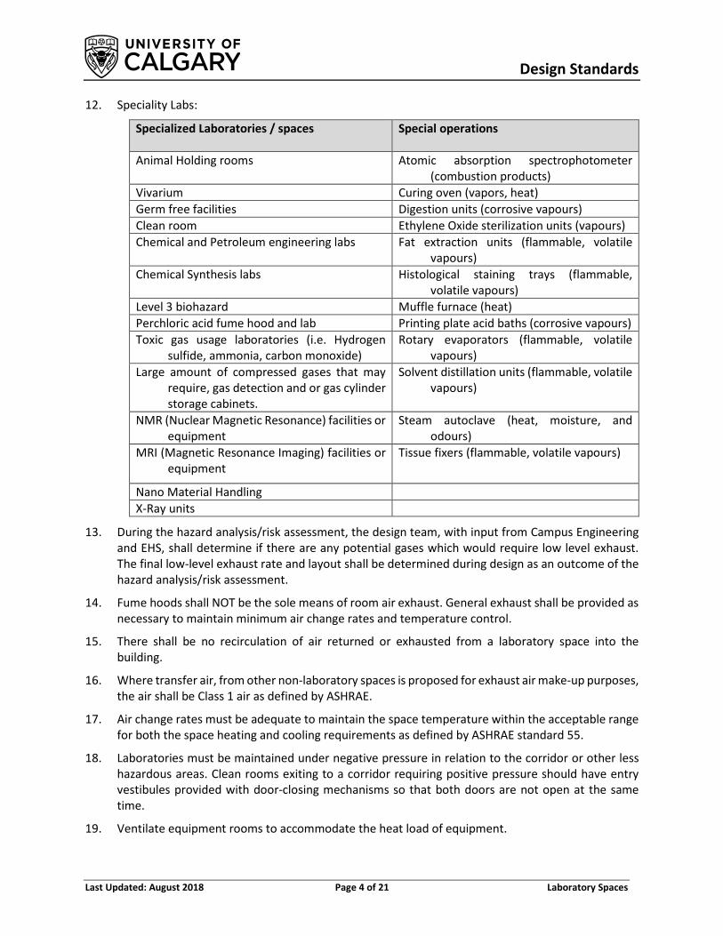
12. Speciality Labs:
Specialized Laboratories / spaces Special operations
Animal Holding rooms Atomic absorption spectrophotometer (combustion products)
Vivarium Curing oven (vapors, heat) Germ free facilities Digestion units (corrosive vapours) Clean room Ethylene Oxide sterilization units (vapours) Chemical and Petroleum engineering labs Fat extraction units (flammable, volatile
vapours) Chemical Synthesis labs Histological staining trays (flammable,
volatile vapours) Level 3 biohazard Muffle furnace (heat) Perchloric acid fume hood and lab Printing plate acid baths (corrosive vapours) Toxic gas usage laboratories (i.e. Hydrogen
sulfide, ammonia, carbon monoxide) Rotary evaporators (flammable, volatile
vapours) Large amount of compressed gases that may
require, gas detection and or gas cylinder storage cabinets.
Solvent distillation units (flammable, volatile vapours)
NMR (Nuclear Magnetic Resonance) facilities or equipment
Steam autoclave (heat, moisture, and odours)
MRI (Magnetic Resonance Imaging) facilities or equipment
Tissue fixers (flammable, volatile vapours)
Nano Material Handling X-Ray units
13. During the hazard analysis/risk assessment, the design team, with input from Campus Engineering and EHS, shall determine if there are any potential gases which would require low level exhaust. The final low-level exhaust rate and layout shall be determined during design as an outcome of the hazard analysis/risk assessment.
14. Fume hoods shall NOT be the sole means of room air exhaust. General exhaust shall be provided as necessary to maintain minimum air change rates and temperature control.
15. There shall be no recirculation of air returned or exhausted from a laboratory space into the building.
16. Where transfer air, from other non-laboratory spaces is proposed for exhaust air make-up purposes, the air shall be Class 1 air as defined by ASHRAE.
17. Air change rates must be adequate to maintain the space temperature within the acceptable range for both the space heating and cooling requirements as defined by ASHRAE standard 55.
18. Laboratories must be maintained under negative pressure in relation to the corridor or other less hazardous areas. Clean rooms exiting to a corridor requiring positive pressure should have entry vestibules provided with door-closing mechanisms so that both doors are not open at the same time.
19. Ventilate equipment rooms to accommodate the heat load of equipment.

Design Standards
Last Updated: August 2018 Page 5 of 21 Laboratory Spaces
6.3.5 Laboratory Air Systems
1. Air Handling Units
a. Air handling units shall be designed and specified to comply with the requirements of University of Calgary Design Standards “Air Handling Systems” Section 5.16.13.
b. All primary air handling units shall use a fan array fan arrangement for supply air with appropriate controls to maintain adequate redundancy.
c. For filter requirements refer to University of Calgary Design Standards “Air Handling Systems - Filtration” Section 5.16.13.4.
2. Supply and Exhaust Terminal Units
a. All labs with variable air volume fume hoods, shall use pressure independent venturi type air valves, with an accuracy of 5%, for fume hood exhaust control.
b. Variable air volume terminal units serving general lab supply air and exhaust shall use pressure independent venturi type air valves or fast acting VAV dampers to maintain pressurization and temperature control.
c. All valves shall be capable of communicating with the BMS via BACnet. Some UC buildings do not have BACnet capability. Check with Campus Engineering.
d. All exhaust air valves shall be stainless steel construction. Alternate corrosion resistant coatings may be considered during design. (e.g. Heresite)
e. All supply air valves shall be galvanized steel construction.
f. All Lab fume hood exhaust air valves shall be suitable for both horizontal and vertical installations.
g. Acceptable pressure independent venturi type valve manufacturers are:
o Phoenix
o Siemens
o Alternates may be accepted upon review by Campus Engineering, Engineer of Record and U of C Controls Group.
h. Lab pressurization control shall use flow tracking control as described in the ASHRAE Lab Design Guide Current Edition. Use of other control strategies must be specifically approved by Campus Engineering.
3. Laboratory Supply and Exhaust Air Outlets
a. Supply air diffusers shall be selected and located in accordance with the recommendations provided in the ASHRAE Lab Design Guide Latest Edition.
b. Supply air diffusers shall be low velocity type with a maximum velocity of 15 m/min (50 fpm) below 2.1m (7 ft) AFF.
c. Supply air diffusers in lab applications, deemed critical by EHS and Campus Engineering, shall be low velocity type with a maximum velocity of 6 m/min (20 fpm) below 2.1m (7 ft) AFF.
d. Laminar flow diffusers with controlled discharge velocity are required.

Design Standards
Last Updated: August 2018 Page 6 of 21 Laboratory Spaces
e. Room air exhaust and supply air outlets must be located as far away as possible from fume hood sashes but at a minimum they must maintain a 1.5m distance from all fume hood sashes.
f. Where the prescriptive requirements for the type and location of diffusers relative to fume hoods is not maintained, or at the discretion of EHS and Campus Engineering, use of computer modelling, or other appropriate methods to demonstrate airflow patterns do not disturb fume hood containment are required.
4. Exhaust Fans
a. Exhaust fans from fume hoods or local exhaust control systems must be positioned as close as possible to point of final discharge. Each fan should be the last element of the system besides the exhaust stack so that the ductwork through the building remains under negative pressure. If a fume hood exhaust fan is located in a mechanical space inside the building, steps must be made to ensure that there are no leaks in the system that will allow contaminants to escape from the fan discharge duct into the surrounding spaces.
b. All lab exhaust fans shall be an up-blast configuration with either a discharge stack or high-plume exhaust.
c. Exhaust stacks from fume hoods and general exhaust control systems should provide a minimum discharge velocity of 15.2 m/s (3000 fpm) unless a dispersion study is completed and confirms a lower velocity is acceptable.
d. Computer modelling (e.g. dispersion study) wind tunnel testing shall be completed to demonstrate the contaminated air is not being re-entrained into the Lab building or an adjacent building;
e. When it is not feasible to maintain the exhaust system discharge requirements.
f. In variable volume exhaust systems where the exhaust plume discharge velocity will vary, designers shall provide a model (e.g. dispersion study) to demonstrate contaminated air is not being re-entrained into the Lab building or an adjacent building.
g. A minimum of 10 m shall be provided between fume hood/lab exhaust outlets and building openings, including doors and openable windows, in accordance with ASHRAE 62.1. Building openings on adjacent buildings shall also be identified and avoided.
h. A minimum of 30 m shall be provided between fume hood/lab exhaust outlets and fresh air intakes. Building fresh air intakes on adjacent buildings shall also be identified and avoided.
i. Consider clustering discharge ductwork or using outside air induction to help dilute discharges and increase effective stack height by increasing air column mass.
j. For fume hood and general exhaust systems provide N+1 redundant fans manifolded together complete with motorized dampers on the fan inlet and outlet to enable fan maintenance without a loss of service.
k. Provide rain protection on stack discharge. Rain protection shall not decrease discharge air velocity or deflect air downward.

Design Standards
Last Updated: August 2018 Page 7 of 21 Laboratory Spaces
l. Exhaust stacks shall be complete with drains.
m. All exhaust stacks shall be supported in accordance with the fan manufacturers recommendations and good engineering practice.
n. All exhaust fans shall be connected to the BMS and shall automatically start the back-up fan in the event of fan failure.
o. Laboratory ventilation exhaust fans shall be spark-proof. V-belt drives shall be static conductive.
p. If highly corrosive chemicals are to be used in the labs, the exhaust fans shall be constructed of corrosion resistant materials for the chemicals being transported,
q. Vibration isolators shall be used to mount fans.
r. Flexible connections to ductwork, such as neoprene coated glass fiber cloth, shall be used between the fan and its intake duct when such material is compatible with hood chemical use. When highly corrosive chemicals are expected do not use flex connectors and attach stainless steel duct directly to exhaust fan.
s. Do not use flexible connectors on discharge side of exhaust fans.
t. Access to electrical disconnects on all exhaust fans must be considered during design.
u. Special consideration must be given to safe access of all fan systems for maintenance and repair. A work surface platform and / or fall protection SHALL be provided if the fan is located within 3 meters of a drop exceeding 1.5 meters. Consult U of C EHS when considering these systems.
v. The following list of manufacturers is acceptable for stack exhaust fans:
o Greenheck
o Penn
o LorenCook
w. The following list of manufacturers is acceptable for high plume exhaust fans:
o Greenheck
o Strobic
o Fire detection, fire suppression and gas detection alarm systems shall not be interlocked to automatically shut down chemical fume hood exhaust fans.
5. General Exhaust and Fume Hood Duct construction
a. All ductwork shall be designed and specified in accordance with
o SMACNA construction standards o NFPA 91 requirements

Design Standards
Last Updated: August 2018 Page 8 of 21 Laboratory Spaces
o Shall be constructed to SMACNA Seal Class A or B for the appropriate rated working pressure.
b. The ductwork from all fume hoods shall be of stainless steel construction between the fume hood outlet and the connection to any common fume hood exhaust duct, header, manifold or riser, regardless of the common exhaust duct, header, manifold or riser construction. Individually vented fume hoods shall be entirely of stainless steel construction.
c. For common exhaust ducts, headers, manifolds or risers serving more than one fume hood the common exhaust duct, header, manifold or riser shall be entirely of stainless steel construction to two duct diameters beyond the point of connection of the 5th fume hood. Beyond this point the common exhaust duct, header, manifold or riser may be of galvanized steel construction.
d. During the lab hazard analysis/risk assessment phase of a project, the design team, along with input from Campus Engineering and EHS shall determine if there are any corrosive chemicals or processes (i.e. most electroplating solutions are not corrosive but can create highly corrosive fumes during the process) which will require specific corrosion resistant ductwork.
e. Fume hood ductwork shall not be fitted with fire or smoke dampers.
f. Where fume hood ductwork must pass through a fire barrier, use fire wrap 3 m (10 feet) on each side of fire barrier as per NFPA 91.
g. Backdraft dampers are not acceptable on lab exhaust ductwork, motorized dampers shall be used.
h. No internal duct lining is allowed in lab exhaust ductwork.
i. Flexible ductwork is not acceptable.
j. All positive pressure ductwork downstream of an exhaust fan serving lab or fume hood exhaust shall be fully welded.
k. Clearly label all fume hood and lab general exhaust ductwork. Refer to 5.16.26 “Identification of Mechanical Systems” for labelling details.
6. Supply Duct
a. Flex duct of any length is strictly prohibited in labs.
6.3.6 Energy Recovery
1. Laboratories shall be designed in accordance with the energy use requirements outlined in the Design Criteria (Section 5.16.3) of the University of Calgary Design Standards.
2. Any cross-contamination between the exhaust air and supply air on an exhaust air energy recovery system shall not be acceptable.
3. Heat recovery equipment shall operate at a minimum efficiency of 70% for sensible heating capacity measured at peak design conditions.
4. All energy recovery systems shall be provided with controls which have the capability of measuring both the energy used to operate the system and the energy recovered.
5. All heat recovery systems shall be provided will full flow bypass dampers in a separate air stream around both the coil and pre-filter. The by-pass ducting shall be configured:
Design Standards
Last Updated: August 2018 Page 9 of 21 Laboratory Spaces
a. To prevent worker exposure to exhaust airstream while replacing filter or cleaning the coil with the system operational.
b. To enable by-passing the coil when the energy recovered is less than the fan power energy penalty of exhausting air through the coil.
6. Designers should consider energy modelling of heat recover options across the entire range of operating conditions to verify the proposed system energy savings
7. Systems to consider are:
a. Passive heat recovery run-around loops (including Konvecta)
b. Heat pipe systems
c. Active heat recovery chillers/heat pump systems
d. Others as identified by the design team and approved by the University of Calgary Campus Engineering
6.3.7 Fume Hoods
1. Cabinet Design
a. All fume hood suppliers shall be members in good standing with Scientific Equipment and Furniture Association (SEFA)
b. All fume hoods purchased must;
o Comply with the current edition of CSA Z316.5, Fume Hoods and Associated Exhaust Systems.
o Be tested for containment at the factory in accordance with PWGSC MD15128. c. Recirculating fume hoods will not be considered for laboratories.
d. The fume hood liner, baffles and work surface shall be constructed of 16 gauge Type 316 stainless steel and of all welded seamless construction. Interior corners shall have at least a 20 mm radius and all welds ground and polished for ease of decontamination. Work surface shall have a 12 mm high anti-spill front edge.
e. Sash perimeter openings shall be constructed to minimize eddies and promote smooth entry of air into the hood. Complete with a 40 mm slot between its underside and the work surface with access for oversized electrical plugs.
f. Sash windows and light lens to be constructed of laminated or tempered glass. No more than 2.3 kg of force to be required to move the sash through the full travel path and the sash should remain stationary when force is removed.
g. Any deviations to the fume hood construction materials shall be approved by Campus Engineering and EHS.
h. Refer to Supply Chain management for the acceptable fume hood manufacturers list.
i. Fume hoods shall be supplied with a sash limiting device (sash stop) installed to limit the sash travel to the maximum operational opening of 450 mm (18”) as measured from the work surface. Sash stops shall be designed to allow the operator to override them but will

Design Standards
Last Updated: August 2018 Page 10 of 21 Laboratory Spaces
automatically reset when the sash is lowered back to below 450 mm (18”). The fume hood must be equipped with an alarm to indicate that the sash is above the maximum operational opening.
j. Fume hoods shall be equipped with an audible and visual low airflow alarm that will sound if the face velocity should drop below 80% of the set point. The audible alarm shall have the ability to be temporarily silenced but the visual alarm must continue to function until face velocity is re-established.
k. If a cup sink is required it will be constructed of the same material as the work surface. It is to be fully integrated with the work surface with a raised edge (minimum 6 mm) to prevent spills from entering drain.
l. Lighting, plumbing and other services are to be accessible for servicing outside of the inner lining.
m. Service controls are to be mounted outside of the cabinet on the front fascia, unless otherwise approved by CE and EHS.
n. All receptacles on fume hoods shall be GFI T-slot 120V/20 A
o. Noise from the fume hood should not exceed 65 dBA at the face of the hood under normal operating conditions.
p. Lighting fixture to be mounted externally of the inner liner, all serviceable electrical parts are to be accessible from outside of the structure.
q. All electrical fixtures will be factory installed and pre-wired to a junction box on the roof of the fume hood superstructure. All components shall bear the CSA and/or UL label.
2. Fume Hood Mechanical Design
a. Fume hood controls shall be arranged so that shutting down one fume hood for maintenance will not affect the exhaust capacity or create an imbalance between exhaust and supply for another hood or local exhaust control manifolded to the same system
b. High efficiency fume hoods shall be selected to provide containment with a minimum face velocity of 60 fpm when tested in accordance with PWGSC MD15128. Final face velocities of the fume hoods will be determined during design with input from Campus Engineering and EHS.
c. For projects where the total fume hood exhaust rate is less than the room general exhaust rate, standard efficiency fume hoods which provide containment with a minimum face velocity of 100 fpm when tested in accordance with PWGSC MD15128, may be used if approved by the Campus Engineering and EHS.
d. Fume hood controls shall be provided with hardwired feedback between the air valve and fume hood controller to quickly react to changes in sash position to maintain containment.
e. Fume hoods in research labs shall be provided complete with occupancy sensors and automatic sash closers.
f. Fume hoods shall be connected to the BMS, via BACnet. The BMS shall display:
o Airflow o Sash position o Emergency Purge

Design Standards
Last Updated: August 2018 Page 11 of 21 Laboratory Spaces
o Alarm o Occupancy (Research fume hoods only)
g. The specification for all new fume hoods installed shall include a requirement for the manufacturer to conduct “As Installed” containment testing in accordance with PWGSC MD15128.
h. VAV systems shall be designed to allow fume hoods to be operated in an emergency mode which will boost the exhaust rate to 100% of the maximum operating air volume (purge mode at 10 AC/hr), regardless of the sash position, to increase the negative pressurization of the room in case of a spill.
i. The requirement for natural gas, water, compressed air and vacuum within fume hoods shall be confirmed with the University of Calgary during the design process.
j. Fume hoods with a water supply shall have a drain that discharges to a separate solids interceptor and to a neutralizing or dilution tank that is connected to a sanitary drainage system through a trap, or indirect connection.
3. Fume Hoods for use with perchloric acid are of a special design and must meet all the requirements of the most recent version of CSA Z316.5. Perchloric acid hoods must be separately ducted from other hoods and local exhaust control.
6.3.8 Biosafety Cabinets (BSCs) in Laboratory 1. All BSCs must comply with the Canadian Biosafety Standards and Guidelines and be certified in
accordance with NSF/ANSI 49 for Biosafety Cabinetry, or, where not applicable, with manufacturer’s specifications.
2. The most commonly used BSC for work involving biohazards at the university is a Class II, Type A2 biosafety cabinet that provides personnel, product and environmental protection.
3. These biosafety cabinets: maintain a minimum average inflow velocity of 100 ft/min (0.51 m/s) through the work access opening; have HEPA filtered downflow air that is a portion of the mixed downflow and inflow air from a common exhaust plenum; may exhaust HEPA filtered air back into the laboratory or to the environment through an exhaust canopy; and
4. All biologically contaminated ducts and plenums are to be under negative pressure or surrounded by negative pressure ducts and plenums.
5. Class II, Type A2 BSCs must be exhausted through properly functioning exhaust canopies (i.e. thimble-connected ) if used for work with minute quantities of volatile toxic chemicals and tracer amounts of radionuclides required as an adjunct to microbiological studies.
6. EHS Biosafety Officer must be consulted prior to designing any exhaust ducting for any BSC. Special applications that may require ducting for a Biosafety cabinet must be reviewed by CE and EHS.
7. All BSCs to be supported by emergency power when used in a Containment Level 2 small animal facility.
8. BSCs shall be positioned so that they are out of the normal flow of traffic pattern and away from interfering air currents, such as those caused by doorways or general ventilation devices. Biosafety cabinets must not be located directly across from, or adjacent to, seated work stations, other biosafety cabinets or fume hoods.

Design Standards
Last Updated: August 2018 Page 12 of 21 Laboratory Spaces
9. Room air exhaust and supply diffusers must be at least 1.5 meters (in the horizontal plane) from the front face of BSCs. The distance can be reduced if using velocity controlled diffusers with a maximum throw velocity of 15 m/m @ 1 m from diffuser.
10. A minimum 40 cm clearance must be provided between the exhaust outlet on top of the BSC and any overhead obstructions. 30 cm must be provided on each side of the BSC.
11. Provision of natural gas to BSCs is prohibited.
6.3.9 Plumbing Systems
1. Sanitary lines
a. Lab sanitary drainage piping shall be schedule 40 CPVC using solvent welded socket joints or schedule 40 Polypropylene pipe connected with mechanical joints.
b. Consideration with respect to routing PVC piping through chases, shafts fire rated assemblies shall be considered by the design team throughout the design process.
c. If known highly corrosive materials are anticipated during design, alternate pipe materials shall be used.
d. Neutralisation/dilution tanks are required on all lab drainage systems (from lab sinks and fume hoods).
e. No floor drains in labs with the exception of the one beneath the emergency station.
f. A solids interceptor is required on all lab drainage systems prior to discharging into local or central neutralization/dilution tanks.
g. Bottle traps are not acceptable in place of sediment sumps.
h. Piping upstream of solids interceptor neutralizing/dilution tank shall be chemically resistant for the planned chemicals.
i. Laboratory drainage piping shall be exposed at rear of casework. Drainage piping is not acceptable in drywall walls.
j. Acid vents shall be collected separately from building venting and shall discharge directly through the roof.
k. Cleanouts on acid waste systems shall extend 150mm above the flood level.
l. Pipe sleeves should extend 50mm AFF to prevent chemicals from draining down to floors below.
m. Floor drain covers and drain bodies shall be constructed of corrosion resistant materials.
n. Traps are required before neutralizing/dilution tank (NPC).
o. Central Building Neutralisation/Tanks are preferred but local acid neutralisation/dilution tanks are acceptable if required but shall be approved by Campus Engineering and EHS.
p. The final number and location of local acid neutralisation/dilution tanks and sediment sumps shall be approved by Campus Engineering and FM. Access for future maintenance is critical.
2. Separation of Potable Water / Non-potable Water Systems
a. Laboratory fixtures shall be served from a dedicated water supply equipped with a Reduced Pressure (RPZ) back flow device to separate it from the potable water service. Where a
Design Standards
Last Updated: August 2018 Page 13 of 21 Laboratory Spaces
laboratory water system is provided, all connected outlets shall be labeled "Non Potable." Faucets, to which a hose or similar device may be attached, shall be provided with an approved vacuum breaker.
b. All non-potable water shall be labelled as specified in section 5.16 of the University of Calgary Design Standards.
c. Backflow preventers shall be installed in accessible locations with the final location approved by Campus Engineering and Facilities Management prior to installation.
d. A central backflow preventer (with redundancy to allow for interrupted supply during servicing) serving multiple fixtures is preferred to multiple units installed at the point of use.
e. Water aspirators are not an acceptable form of backflow prevention.
3. Each laboratory must contain a sink, dedicated for hand washing, with hands free capability located near the exit. This sink is typically integral with the Emergency Station module (see point 4)
4. Each lab shall have an Emergency Station as specified in Section 6.3.15 “Emergency Fixtures and Stations” of this Standard. Emergency Eyewash and Shower MUST be on potable water system.
5. Laboratory Gases
a. Provide shut-off valves in accessible locations for central supply of flammable, combustible or oxidizing gases. Valves shall be identified and located outside of the areas in which the gases are used. These shut-off valves are in addition to those at the points of supply and use.
b. Switches or buttons for emergency gas shut-off valves shall be located adjacent to the corridor exit from the lab.
c. Storage and supply systems for compressed and liquefied gases shall comply with requirements of the NFPA and ANSI.
6. Reverse Osmosis (RO) water
a. RO piping shall be schedule 40 CPVC or Polypropylene pipe connected with butt-welded joints free of interior grooves.
b. Solvent joining of RO piping is not acceptable.
c. Pipes shall be hung as per the manufacturer’s instructions.
d. RO systems shall be designed with recirculation systems to eliminate standing water in the pipes and avoid biological growth.
e. RO systems shall be designed with a minimum pipe velocity of 4 fps to avoid biological growth. Consideration must be given to the manufacturer’s maximum recommended pipe velocity.
f. RO quality shall be Type II with a conductivity less than 1 µS/cm
6.3.10 Centralized compressed air systems
1. Compressed air distribution system must be sized to deliver air at 690 kPa.
2. Consider the use of an air dryer as part of the compressed air system.
3. Dual compressor (duplex) VFD driven arrangements are preferred. This will provide 100% redundancy it case of a compressor failure.

Design Standards
Last Updated: August 2018 Page 14 of 21 Laboratory Spaces
4. Size laboratory compressed air piping based on 0.24 l/s per laboratory air outlet (unless actual flow is known) plus any known flow required for specific pieces of lab equipment. Apply a reasonable diversity factor to the compressed air outlets based on the size of the system.
5. Oil free compressors shall comply with ISO 8573.
6. This system shall not be sized for fire protection systems (pre-action), neither high temperature heating system control valves in vaults. It will only serve laboratory compressed air outlets and equipment.
• Approved products: Ingersoll-Rand, DV Systems
6.3.11 Centralized vacuum systems
1. Provide central building laboratory vacuum system with an ASME receiver where practical. Duplex (or any other arrangement that will allow 100% redundancy) liquid ring pumps are the preferred type. Provide a liquid trap upstream of the receiver. Consider water conservation options for vacuum pumps unit selections. Air cooled vacuum pumps are acceptable if cooling water is not available, check with Campus Engineering.
2. The building central vacuum system will be sized to limit pressure drop across the system to a maximum of 76.2 mmHg.
3. Size laboratory vacuum piping based on 0.24 l/s per laboratory vacuum outlet (unless actual flow is known) plus any known flow required for specifics pieces of lab equipment. Apply reasonable diversity factors to system inlets based on the size of the system.
4. Vacuum pumps will be controlled by a pressure switch in the receiver set to operate between 559 and 635 mmHg.
5. Branch vacuum lines shall be connected to the top of horizontal main vacuum piping. To ensure no low spots that would collect or trap liquids in the vacuum lines.
6. Each pump shall be air-cooled and have absolutely no water requirements
7. All pumps shall be tank mounted. Pumps shall be connected to a common manifold and piped to an SME horizontal receiver, galvanised inside and outside, complete with Canadian Registration Number, drain valve, vent valve and sight glass.
8. Provide one externally and internally epoxy coated medical vacuum filter per pump. Provide one RTD (Resistance Temperature Detector) discharge temperature sensor per pump
9. Approved Products: Power, Class 1
6.3.12 Natural Gas
1. All new labs or major renovations requiring natural gas should be provided with an emergency shut-off solenoid valve and mushroom type push button in close proximity to the lab exit. Push button shall be keyed type for resetting purposes. Natural gas solenoid valve shall fail closed in a power outrage and remain closed when power is re-established. Only operations personal can have a key to reset solenoid valves.
2. All millwork mounted laboratory natural gas turrets to be push/turn type

Design Standards
Last Updated: August 2018 Page 15 of 21 Laboratory Spaces
3. Approved Products and manufacturer: Water Server CT2860I-232SWSA (double), CT2860I-231SWSA (single), other configurations also available from manufacturer.
4. Alternative manufactures may be approved by Campus Engineering
6.3.13 Hazardous Material / Flammable Storage
Flammable storage cabinets should be located under or adjacent to the fume hood. Current UofC practice/expectation is ….when a fume hood is install in a laboratory the installation will also include is one flammable and one corrosive storage cabinet.
When multiply fume hoods are installed in a laboratory the number of corrosive and flammable storage cabinets may be modified from 1 to 1 ratio of each type. At a minimum at least one flammable cabinet and one corrosive cabinet installed when multiply fume hoods are installed.
1. Flammable storage cabinets shall not be located within 1 metre of any exit or in a location that would impede leaving the area.
2. Flammable storage cabinets must conform to ULC/ORD-C1275.
3. Flammable storage cabinets are not required to be vented for fire protection purposes and venting may compromise the specific performance of the cabinet. However, the cabinet must be supplied with factory furnished vent ports, fitted with flame arrestors, and removable seals should venting be required for the purposes of protecting workers to exposure of harmful vapours.
4. EHS must be consulted prior to venting of flammable storage cabinets.
5. If a cabinet is vented then the duct must be constructed of stainless steel or a material providing similar protection as the cabinet seals.
6. Ducts should be attached to the lower vent port. Care must be made to retain seals should the need to vent the cabinet be reversed in which case the cabinet vent ports must be sealed.
7. Ducts should be connected to the main fume hood exhaust duct and after the fume hood connection if manifolded or if the fume hood is VAV operation at least 300 mm downstream of control valve.
8. At no time should a flammable storage cabinet be cut, drilled or altered or modified to make connections for venting, mounting to walls or for any other purpose that may compromise the integrity of the fire protection.
9. If product is to be dispensed directly from a flammable storage cabinet then the cabinet must be grounded.
10. Corrosion resistant cabinets are required for the storage of acids. These cupboards are to be vented using lab line to prevent deterioration due to corrosion or rusting. Venting may be done into adjacent fume hoods as per the manufacturer’s specification.

Design Standards
Last Updated: August 2018 Page 16 of 21 Laboratory Spaces
6.3.14 Emergency Fixtures and Stations
1. Laboratories using hazardous materials must have an eyewash and safety shower capable of delivering 15 minutes of continual flow within 15 meters or 10 seconds travel time from the chemical use areas
2. Eyewashes and safety showers purchased must be from the University’s list of approved devices and installed in conformance with ANSI Z358.1-– Latest Edition Standard for Emergency Eyewash and Shower Equipment
3. Water delivered to eyewash and safety showers must be tempered to deliver water at a temperature between 20° and 25° C. The tempering valve must be designed to fail to cold
4. Locate safety showers and eyewashes such that no live electrical outlets or equipment will be contacted when activated. Receptacles within 1.5 meters of the eyewash or shower must be equipped with a Class A ground fault circuit interrupter
5. When separate eyewash and shower units are installed the eyewash and shower will be located so that both can be operated at the same time by the same user
6. A sign indicating the presence of the safety shower and /or eyewash equipment must be positioned in a highly visible location
7. Eyewashes must have drains that connect directly to drainage piping and safety showers must be situated near self priming floor drains
8. Fire extinguishers appropriate for the chemicals and equipment in use must be installed near the entrance of each laboratory. The default extinguisher is a five pound ABC
9. Refer to Table 1 below for a list of acceptable plumbing fixtures and trim drawing below for typical Emergency Station Detail. See list of acceptable plumbing fixtures and trim.
Trim Description Manufacturer Model
Hand Wash Lab Sink Novanni 4207ADE10 Elkay WLC1923OSDC
Hand Wash Lab Sink Faucet Sloan EFX-250 -000-0100
Combination Emergency Eye Wash and Shower Mixing Valve Haws 9201E
Emergency Eye Wash – Sink Mounted, swing type
Haws 7610
Emergency Shower Haws 8164 (1)
(1)Consider a pull rod option when lever assembly installation becomes difficult (i.e. block or concrete walls, etc)
Table 1
10. Refer to Figure 1 below for typical Emergency Station Detail.

Design Standards
Last Updated: August 2018 Page 17 of 21 Laboratory Spaces
6.3.15 Figure 1Gas Detection Systems
Where fixed gas detection is deemed a requirement, please refer to the latest version the "Fixed Gas Detection Standard" as issued by the University of Calgary's EHS department. This document can be found by clicking the following link: http://www.ucalgary.ca/safety/program
6.3.16 Freezer Farms / -80°C Freezer Standards
Refer to the University of Calgary Design Standards, Bio Banks (-80°C ULT Freezer Farms) Requirements, Section 6.17
6.3.17 Compressed Gases
1. Storage and supply systems for compressed and liquefied gases shall comply with requirements of the NFPA and ANSI.
2. Prior to designing ventilation for gas cylinder cabinets refer to section 6.3.4.4
3. Specify gas cylinder cabinet and manufacturer/supplier. Models from different manufacturers are typically NOT interchangeable for application.

Design Standards
Last Updated: August 2018 Page 18 of 21 Laboratory Spaces
4. Manufacturer required rates will be reviewed by design team prior completion of ventilation design.
6.3.18 Provisions for power outages
1. The University may require some hoods to continue operation during a power outage and should therefore be connected to a back-up power source. Consult with Campus Engineering and EHS prior to design.
2. Any fume hood that is not connected to an exhaust system with back-up power shall at least have the local control/alarm panel for each hood connected to back-up power. Fume Hoods that lose containment during a power outage would then be able to emit the audible ‘low-flow’ alarm.
3. Fume hoods air valves shall be equipped with safe open spring return dampers.
4. NG solenoid (refer to section 6.3.13 Natural Gas in this standard)
6.3.19 Commissioning / Handover
1. Design Engineer to ensure that the basic Commissioning requirements listed below are included in the appropriate sections of the specification. Should a third party Commissioning agent be retained by the University then they would be responsible for providing a full Commissioning specification to the Prime Consultant for inclusion into the contract documents.
Commissioning requirements:
a. Fume hood and air system functional tests including purge mode, unoccupied mode and overrides
b. Air balancing of fume hood(s), exhaust air and supply air systems. c. Fume Hood sash height and face velocity labelling MUST be completed. d. Shower / Eyewash station checklist complete (per ANSI Standard) and tag MUST be filled out. e. Copy of all “As installed” fume hood containment test results f. Operational instructions for the fume hood are attached to unit or presented to occupants and
a copy forwarded to EHS for upload to website g. Fume hood training including Operator Display Panel Operation and warning light and alarm
meanings h. Proper sealing of cabinetry joints, flooring and wall joints. i. Verify gas solenoid operation j. RO water quality report k. Sinks / plumbing l. Operational tests of all isolation valves m. All valve and equipment tagging complete, including controls “luggage” tags. n. Separate training sessions for lab personnel and Operations staff o. Functional testing of gas detection system (if equipped)
6.3.20 Control Strategy for Labs
1. This Section is currently under review. Please consult with Campus Engineering, UC Controls group and EH&S when designing any control strategy for laboratories.

Design Standards
Last Updated: August 2018 Page 19 of 21 Laboratory Spaces
2. Designer is required to provide final sequence of operation to Campus Engineering at Design Phase.
6.3.21 Architectural
1. Cabinetry, equipment, or other structures should not block or reduce effectiveness of supply or exhaust air
2. Provide hangers near the exit near the exit for hanging lab coats separately from street clothing. Do not use hooks that protrude
3. An area, preferably near an exit from the lab, will be designated as a life safety zone. This area will be used for eye wash/ safety shower installation, hand washing sink, mounting a fire extinguisher, mounting a first aid kit, emergency gas shut-off and storage of a spill kit
4. Operable windows are prohibited in laboratories in new buildings and should be avoided when modifying existing buildings
5. Laboratories must be separated from public spaces by a lockable door
6. Office areas are to be located in order of preference:
a. Outside of the lab
b. Separated from the lab at the front as a separate room within the lab or a vestibule to the lab
c. Placement of office space within the lab is discouraged but if required must be located near the exit and away from areas of higher contamination
d. If office areas are located in a lab then lockers for the storage of personal belongings and outdoor clothing must be provided away from areas of higher contamination and preferably outside of the lab
7. Aisles serving a single work area shall be a minimum of 910 mm wide. Double aisles shall be a minimum of 1525 mm wide. Mobile equipment, carts and so on should not be permitted to reduce the aisle width to less than 1200 mm. Avoid aisles longer than 6 m. Arrange furniture for easy access to an exit from any point in the laboratory
8. Laboratory floors are preferred to be polished concrete. Radioactive labs are required to have a strippable coating to allow for removal of contamination. If resilient is used it should be smooth, non-porous, seamless sheet that is resistant to a wide range of chemicals. The sheets shall be coved along walls and permanently placed furnishings. Floor openings shall be sealed watertight
9. Walls and doors shall be constructed or painted with a smooth, non-absorbent, washable material
10. Areas of higher hazard should not be located near doors exiting the area
11. Fume hoods shall be positioned so that they are out of the normal flow of traffic pattern and away from interfering air currents, such as those caused by doorways or general ventilation devices. Ideally fume hoods are located at the back of the room and away from doorways. Fume hoods shall not be located adjacent to a single means of access to an exit or to high traffic areas. Fume hoods must not be located across from seated work stations or across from or adjacent to biological safety cabinets. It is recommended that fume hoods not be located across from other fume hoods. Figures 1 and Figure 2 represent the recommended and non recommended clearances and positioning of fume hood

Design Standards
Last Updated: August 2018 Page 20 of 21 Laboratory Spaces
Figure 1: Fumehood Location – Clearances (Taken from CSA Z316.5-04 Fume Hoods and Associated Exhaust Systems)

Design Standards
Last Updated: August 2018 Page 21 of 21 Laboratory Spaces
Figure 2: Fumehood Location on Floor Plan (Taken from CSA Z316.5-04 Fume Hoods and Associated Exhaust Systems)