design specifications for an emergency vehicle …whitmore/courses/ensc305/projects/2008/...vehicle,...
TRANSCRIPT

© 2008, Enlightenment Solutions Corp.
November 6, 2008 Dr. Andrew Rawicz School of Engineering Science Simon Fraser University Burnaby, British Columbia V5A 1S6 Re: ENSC 440 Design Specifications for an Emergency Vehicle Traffic Control System Dear Dr. Rawicz: The attached document, Design Specifications for an Emergency Vehicle Traffic Control System, outlines the requirements of the project for ENSC 440. Our development will employ a new traffic light system that will incorporate a response from approaching emergency vehicles. The design is a response to several tragic incidences involving emergency vehicles and civilians colliding within intersections. The purpose of this document is to describe in detail the design specifications of the different components within the system. The different parts of the system consist of a GPS unit, a RF transmitter-receiver pair and traffic light controller processor. They each have individual design requirements as well as integrated, multi-module requirements. ESC is company that is governed by five senior engineering students. Our background in the field is diverse and covers a broad range from software to hardware to mechanical engineering. Ryan Goldade, Leon Chang, Kelvin Liu, Jung Jun Kim and Tae-Hoon Kim have teamed up to bring their various strengths to the table in developing the new advancement in emergency response technology. Please contact Ryan Goldade through e-mail, [email protected], if you have any concerns or questions regarding the design specification. Sincerely, Ryan Goldade, CEO Enlightenment Solutions Corporation

Design Specification Emergency Vehicle Traffic Control System
Project Team: Kelvin Liu Ryan Goldade Jung Jun Kim Tae Hoon Kim Leon Chang Contact Person: Ryan Goldade [email protected] Submitted to: Dr. Andrew Rawicz – ENSC 440 Mike Sjoerdsma – ENSC 305 School of Engineering Science Simon Fraser University Issued Date: November 6, 2008 Revision: 1.4

© 2008, Enlightenment Solutions Corp.
ii
Executive Summary Motor vehicle codes often grant an emergency vehicle (EMV) the right to disregard the rules of the road when responding to an emergency. Of course, in doing so, the EMV must not endanger people or property under any circumstances. However, miscommunication between EMV operators and civilian drivers can potentially lead to serious accidents. In fact, intersections are the locations responsible for a large percentage of major accidents involving emergency vehicles. It becomes obvious that the injuries and deaths associated with emergency vehicle accidents can be dramatically reduced with advancements in today’s technology. This Emergency Vehicle Traffic-light Control (EVTC) utilizes GPS signal to compute the velocity and location of an emergency vehicle, these data are wirelessly sent to the traffic light that is being approached. The traffic light will make use of the received information and allow easy passage for the emergency vehicle accordingly. The purpose of this document is to specify the design and development for the proof-of-concept prototype of the EVTC system. The development of EVTC is decomposed into three major modules: GPS module, RF module and traffic light module. Each module is developed and tested independently in parallel and its implementation and configurations will be discussed. The main functionalities of each module are listed below.
GPS module : Acquire accurate position of an EMV RF module : Transmit EMV’s position to the traffic light module Traffic light module : Perform traffic light preemption
The design specifications in this document correspond to the consideration pertaining to the functional requirement marked I as specified in the document Functional Specification for the Emergency Vehicle Traffic-light Control System [1]. The completion date of the first prototype is December, 2008.

© 2008, Enlightenment Solutions Corp.
iii
Table of Contents
Executive Summary .........................................................................................................ii List of Figures..................................................................................................................iv List of Tables...................................................................................................................iv List of Equations..............................................................................................................iv Acronyms ........................................................................................................................ v Acronyms ........................................................................................................................ v Glossary ..........................................................................................................................vi 1. Introduction ................................................................................................................. 1
1.1 Scope................................................................................................................ 1 1.2 Intended Audience ............................................................................................ 1
2. System Overview ........................................................................................................ 2 3. On-Board GPS Module ............................................................................................... 3
3.1 General Overview of the GPS Module and Antenna.............................................. 4 3.1.1 ZX4120 GPS Module ...................................................................................... 4 3.1.2 Antenna........................................................................................................... 5
3.2 Hardware design of On-Board GPS System Interface........................................... 6 3.2.1 Connecting ZX4120 GPS Module Using a Voltage Regulator......................... 6 3.2.2 ZX4120 Module Interface with the RF Module ................................................ 7
3.3 GPS Data with NMEA Protocol.............................................................................. 8 4. RF Module................................................................................................................... 9
4.1 CC1110 Overview................................................................................................ 10 4.2 CC1110 Interface................................................................................................. 12
4.2.1 Mapping the UART Peripheral ...................................................................... 12 4.2.2 Setting up the UART Protocol ....................................................................... 13 4.2.3 Processing UART Communication Using UART ISR .................................... 15
4.3 Radio Configuration ............................................................................................. 15 4.4 Radio Communication ......................................................................................... 16
4.4.1 Radio Transmission ...................................................................................... 16 4.4.2 Radio Recepton ............................................................................................ 16
5. Traffic Light Module / LED......................................................................................... 18 5.1 Microcontroller ..................................................................................................... 18 5.2 Traffic Light Control Algorithm ............................................................................. 19 5.3 Traffic light Simulation ......................................................................................... 22
5.3.1 LED lights...................................................................................................... 22 5.3.2 Schematic ..................................................................................................... 22
6. System Test Plan ...................................................................................................... 24 6.1 GPS Module Performance Testing ...................................................................... 24 6.2 RF Module Performance Testing ......................................................................... 25 6.3 LED lights ............................................................................................................ 28 6.4 CY3681 for Traffic control .................................................................................... 28 6.5 Integration Test.................................................................................................... 28
7. Conclusion ................................................................................................................ 30 8. Sources and References........................................................................................... 31

© 2008, Enlightenment Solutions Corp.
iv
List of Figures Figure 1 - Module Overview ....................................................................................................... 2 Figure 2 - The layout of the ZX4120 GPS Module [2] ............................................................ 4 Figure 3 - System Block Diagram of the GPS system Interface........................................... 6 Figure 4 - The circuit of voltage regulator using LT1086 [2].................................................. 7 Figure 5 - ZX4120 Module Interface with the serial I/O port of the RF Module [2] ............ 7 Figure 6 - RF Module Interface Overview [5].............................................................................. 12 Figure 7 - Interfacing UART with GPS Module/ Traffic Light Module [5]........................... 13 Figure 8 - Serial Data Format [5] ............................................................................................. 14 Figure 9 - Radio data packet format [4] .................................................................................. 15 Figure 10 - Data transfer through the development board .................................................. 18 Figure 11 - Regular operation of the traffic light.................................................................... 20 Figure 12 - Operation during EMV approaching intersection.............................................. 21
List of Tables Table 1 - Pin assignment of ZX4120 [3] ................................................................................... 5 Table 2 - Serial Configuration .................................................................................................... 8 Table 3 - NMEA message formats supported by ZX4120 software [3] ............................... 8 Table 4 - $GPGGA message structure [3] ............................................................................... 9 Table 5 - UART Peripheral I/O Mapping ................................................................................ 13 Table 6 - Incoming/ Outgoing Serial Data Settings .............................................................. 14 Table 7 - Modulation settings for various data rates [4] ....................................................... 16 Table 8 – Typical values of the LED used for traffic light .................................................... 22
List of Equations Equation 1 - UART Baud Rate Generation [5]............................................................... 14

© 2008, Enlightenment Solutions Corp.
v
Acronyms CCA - Clear Channel Assessment CRC – Cyclic Redundancy Check DMA – Direct Memory Access EVTC – Emergency Vehicle Traffic-light Controller GPIO – General Purpose Input Output I/O – Input/ Output ISR – Interrupt Service Routine NMEA - National Marine Electronics Association PER – packet error rate PQI - Preamble Quality Indicator RS232 – Recommended Standard 232 RSSI – Received Signal Strength Indicator SoC – System on Chip SPI – Serial Peripheral Interface TTL – Transistor-transistor Logic UART – Universal Asynchronous serial Receiver and Transmitter USART – Universal Synchronous/ Asynchronous serial Receiver and Transmitter UTC - Coordinated Universal Time

© 2008, Enlightenment Solutions Corp.
vi
Glossary Almanac Data - Information transmitted by each satellite on the orbits and state (health) of every satellite in the GPS constellation. Almanac data allows the GPS receiver to rapidly acquire satellites shortly after it is turned on. Cold start – The power-on sequence where the GPS receiver downloads Almanac data before establishing a position fix. Ephemeris Data - Current satellite position and timing information transmitted as part of the satellite data message. A set of ephemeris data is valid for several hours. Hot Start - The GPS receiver remembers its last calculated position and which satellites were in view, the almanac used, and the UTC Time. This is the quickest re-acquisition of a GPS lock. TTFF – Time To First Fix. TTFF is the time it takes a GPS receiver to find satellites after the user first turns it on (when the GPS receiver has lost memory or has been moved over 300 miles from its last location). Warm start – Time and position known to within some limits, almanac known, at least 3 Ephemeris are known from previous operation.

© 2008, Enlightenment Solutions Corp.
1
1. Introduction Emergency Vehicle Traffic Control (EVTC) system provides traffic light preemption for the emergency vehicle (EMV) in order to reduce accidents and traffic delays. This system utilizes GPS signal to compute the velocity and location of an emergency vehicle, and these data are wirelessly sent to the traffic light that is being approached. The traffic light controller will make use of the received information and allow easy passage for the emergency vehicle accordingly. Moreover, the user of EVTC system is not only the operator in the emergency vehicle but everyone that uses the road system is considered, from other drivers to pedestrians at the intersection. The engineers of Enlightenment Solutions Corporation (ESC) are currently developing the proof-of-concept system, and it is projected to be completed by the target date of December 17, 2008. The final product is targeted for one year from the prototype production date.
1.1 Scope This document describes in detail of the design specifications of EVTC system. This document will serve as guidelines for the engineers of ESC when they develop the modules and create the proof of concept system. The design specification includes all requirements of the project regarding hardware, software, user interface, and test plan. The design specifications discussed in this document are primarily focused on the implementation of the proof-of-concept system, as described in Functional Specification for an Emergency Vehicle Traffic Control System [1], and only briefly outlines some of the production model design specifications.
1.2 Intended Audience This document is primarily targeted towards all team members of Enlightenment Solution Cooperation (ESC) to assist the development process of EVTC system. Furthermore, the team members will be able to ensure whether the design fulfills the functional requirements as described in Functional Specification for an Emergency Vehicle Traffic Control System [1].

© 2008, Enlightenment Solutions Corp.
2
2. System Overview The EVTC system gathers GPS location and passes the information to several modules before the vehicle location is processed. The different modules are chosen because they meet the requirements that were set to achieve a fully functional system. Error! Reference source not found. highlights each individual module.
Emergency Vehicle Traffic Light Controller
RF Receiver
Traffic Micro-Controller
GPS Chip
RF Transmitter
Traffic Light
Antenna
Figure 1 - Module Overview Each individual module was carefully chosen to maximize accuracy, speed and functionality when the entire system works together. The ideology of “Garbage in equals Garbage out” is taken very seriously. This idea implies that if any unit in the system is receiving inaccurate data from its preceding unit, it cannot output anything useful. This is a driving force in out product decision, because the more accurate the data transmission, the better the overall function will be. GPS is the ideal method for locating the vehicles position. It is more accurate than a triangulation method with RF signals, the chip is well priced and the satellite data stream is readily accessible in every urban setting. The RF transmit/receive modules are the best choice for communicating the vehicles location to the traffic light controller. The low –frequency range meets our transmission requirements. Other competitive technologies offer a faster data transmission, but sacrifice range. Because the vehicle’s location is a small amount of information to transfer, these options were ruled out. The traffic light operation is controlled by a stand-alone micro-controller, which will receive an interrupt and a data stream from the RF receiver indicating an approaching vehicle and its location.

© 2008, Enlightenment Solutions Corp.
3
3. On-Board GPS Module The purpose of the on-board GPS system is to simulate the existing GPS system of the emergency vehicles (EMV). It communicates the GPS data of the current EMV’s location to the RF module, and then the data will be transmitted to the traffic light RF module to determine the relative location and the speed of EMV approaching to the traffic light. The components of the on-board GPS system primarily consist of the GPS module and an antenna. The following lists the factors that are considered in choosing the suitable components of the on-board GPS system:
• The GPS module is required to acquire GPS signal continuously and retain high level of accuracy less than 10meters as the most of the GPS module can reach with the current GPS technology
• The GPS module needs to be able to obtain adequate location acquisitions in all weather conditions. Moreover, the cold start, which requires the longest reacquisition, should be less than 1 minutes.
• In order to reduce the complexity of the system implementation, the number of pins used for the GPS module should be minimized.
• The GPS module needs to be able to transmit the relevant GPS data such as UTC time, longitude, and latitude to the RF module via standard NMEA-0183 protocol.
• The antenna is required to send an adequate GPS data to the GPS module in all weather conditions such as rain and snow. Additionally, the antenna should be capable of operating properly under temperature ranges of -30 to 50°C. By meeting these requirements, we will be able to test the GPS system outside.
By considering all the factors listed above, we decided to utilize the ZX4120 GPS module and the matching external active antenna. The following two sections describe how these devices meet the functional requirements listed above as well as the general overview of the devices
© 2008, Enlightenment Solutions Corp.
4
3.1 General Overview of the GPS Module and Antenna
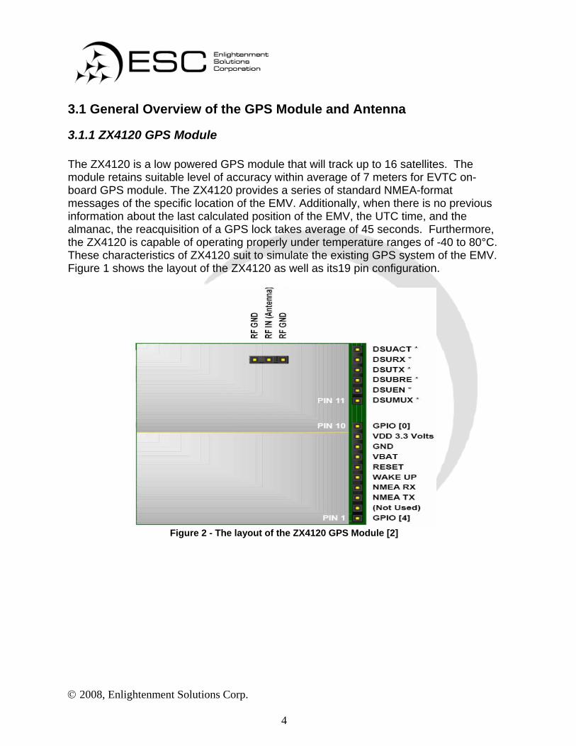
3.1.1 ZX4120 GPS Module The ZX4120 is a low powered GPS module that will track up to 16 satellites. The module retains suitable level of accuracy within average of 7 meters for EVTC on-board GPS module. The ZX4120 provides a series of standard NMEA-format messages of the specific location of the EMV. Additionally, when there is no previous information about the last calculated position of the EMV, the UTC time, and the almanac, the reacquisition of a GPS lock takes average of 45 seconds. Furthermore, the ZX4120 is capable of operating properly under temperature ranges of -40 to 80°C. These characteristics of ZX4120 suit to simulate the existing GPS system of the EMV. Figure 1 shows the layout of the ZX4120 as well as its19 pin configuration.
Figure 2 - The layout of the ZX4120 GPS Module [2]

© 2008, Enlightenment Solutions Corp.
5
A list of pin assignment for the 19-pin ZX4120 shown in Figure 1 is provided in Table 1.
Pin Name Pin Name 1 GPIO [4] 11 DSUMUX 2 NC (MODE) 12 DSUEN 3 NMEA TX 13 DSUBRE 4 NMEA RX 14 DSUTX 5 WAKE UP 15 DSURX 6 Reset 16 DSUACT 7 VBAT 17 RF GND 8 GND 18 RF IN 9 VDD 19 RF GND
10 GPIO [0] Table 1 - Pin assignment of ZX4120 [3]
Since the primary task of the ZX4120 is to receive the RF signal from the active antenna and to communicate the information of EMV’s locations to the RF module, the debug pins (11-16) are not used for EVTC system. The following lists explain the functions of the pins that are used for the on-board GPS system.
• Pin 3 is used to transmit to the RF module via NMEA-0183 protocol • Pin 6 is the active-low reset input • Pin 7 is used to power and retain the internal memory of the GPS for almanac
and ephemeris to assist in the GPS satellite search on the next power up • Pin 8, 17 and 19 are ground • Pin 9 is supplied with 3.3V • Pin 18 is connected to the GPS signal line of antenna
3.1.2 Antenna The matching active antenna with the ZX4120 is built into a sold plastic waterproof housing and its operating temperature is between the temperature ranges of -40 to 85°C. By considering these environmental requirements, it is suitable for outdoor testing in various weather conditions such as rain or snow.

© 2008, Enlightenment Solutions Corp.
6
3.2 Hardware design of On-Board GPS System Interface As the ZX4120 GPS module transmits data via NMEA0183 protocol, the module interacts with the RF transmitter module via a MAX232CPE integrated chip. The system block diagram of the GPS system interface is shown in Figure 2.
Figure 3 - System Block Diagram of the GPS system Interface
3.2.1 Connecting ZX4120 GPS Module Using a Voltage Regulator We are using 9V battery as the power source. However, the ZX4120 requires a primary steady power supply of 3.3 V VDD whereas MAX232CPE operates at a steady 5V. In order to supply these voltages, there are two alternatives, the voltage divider and the voltage regulator. Since using voltage divider produces dependent output voltage from the input voltage, we decided to use a fixed 5V regulator using 7805 chip in order to provide the steady 5V to the MAX232CPE IC. We have also decided to integrate a voltage regulator using LT1086CT-3.3 which can regulate 5V from a battery source to a steady 3.3V to the ZX4120. The following figure shows the configuration of the voltage regulators as well as connection between ZX4120 and the voltage regulator.

© 2008, Enlightenment Solutions Corp.
7
Figure 4 - The circuit of voltage regulator using LT1086 [2]
3.2.2 ZX4120 Module Interface with the RF Module In order for the ZX4120 to interface to the RF module, the MAX232 liner driver is required to allow the ZX4120 to send the GPS data with NMEA message formats through serial RS232 I/O port. The following design circuit was implemented using MAX232CPE.
Figure 5 - ZX4120 Module Interface with the serial I/O port of the RF Module [2]

© 2008, Enlightenment Solutions Corp.
8
3.3 GPS Data with NMEA Protocol The ZX4120 transmits the GPS data to the RF module via standard NMEA 0183 codes by implementing MAX232ACPE, which makes it possible to interface with the RF module. Please note that the ZX4120 is only able to send the GPS data to the RF module with matching serial configurations. The specific configurations are listed in the following table.
Baud rate 9600 Data bits 8
Parity None Stop bits 1
Handshake None Table 2 - Serial Configuration
Furthermore, the ZX4120 software supports the following NMEA message formats shown in the following table. NMEA Message Prefix Format Direction
$GPGGA GPS fix data Out $GPGLL Geographic position Latitude / Longitude Out $GPGSA GNSS DOP and actives satellites Out $GPGSV Satellites in view Out $GPRMC Recommended minimum specific GNSS data Out $GPVTG Velocity and track over ground Out $GPZDA Data and Time Out
Table 3 - NMEA message formats supported by ZX4120 software [3] The default NMEA messages that ZX4120 transmits to the RF module via serial I/O interface are $GPGGA, $GPRMC and $GPVTG. Among these default NMEA messages, we decided to use the $GPGGA format since it transfers suitable data for determining the location of EMV’s such as UTC time, latitude, longitude, and N/S/E/W indicators. The $GPGGA message structure is shown in the following table.
Field Format Notes Message ID $GPGGA GGA protocol header. UTC Time hhmmss.sss Fix time to 1ms accuracy. Latitude Float Degrees*100 + minutes.
N/S Indicator Char N=north or S=south Longitude Float Degrees*100 + minutes.
E/W Indicator Char E=east or W=west Position Fix
Indictor Int 0: Fix not available or invalid.
1: GPS SPS mode. Fix available.

© 2008, Enlightenment Solutions Corp.
9
Satellites Used
Int Number of satellites used to calculate fix.
HDOP Float Horizontal Dilution of Precision. MSL Altitude Float Altitude above mean sea level.
Units Char M Stands for “meters”. Geoid
Separation Int Separation from Geoid, can be blank.
Units Char M stands for “meters” Age of
Differential Int Age in seconds Blank (Null) fields when DGPS is not
used. Table 4 - $GPGGA message structure [3]
Before we integrate the GPS module with the RF module, we have to verify whether the GPS module is actually transmitting GPS data or not. In order to test the interface, we connected the MAX232CPE to the GPS module, and then the MAX232CPE was connected to the PC serial port to allow the NMEA message to be viewed with HyperTerminal. After the ZX4120 transmits the GPS data of the current EMV’s locations, only the relevant data such as UTC time, longitude and latitude will be parsed and transmitted via a software program in the RF module to the traffic light system.
4. RF Module RF module is the most important component of the EVTC system. In order to select the suitable module for EVTC system, many aspects of the functionality and performance of various RF modules were put into consideration. This section will highlight the important items that were put into consideration and details of the RF module chosen for the EVTC system. One of the primary goals of EVTC system is to provide assistance to EMVs with minimal cost and modification to the existing system. This means the RF module will need to be integrated into the existing GPS system of the EMV and traffic light control system with limited change. Balance of the following characteristics has been taken into considerations when choosing the RF module in the order of importance: power consumption, microprocessor, versatility, and most importantly cost and availability.
• Power consumption: EMVs carry various equipments that utilize the power system of the vehicles. In order to minimize the effect of additional equipment, low power module is highly preferred.

© 2008, Enlightenment Solutions Corp.
10
• Microprocessor: RF module needs to have a high performing built-in
microprocessor but it needs to have sufficient level of performance relative to the cost. It needs to effectively handle all the necessary calculations and functions such as communicate with the on board GPS or traffic light control system. As part of the emergency response system, reliability and robustness is of great importance. Built-in microprocessor also reduces the amount of integration and potential error between two unfamiliar RF and microprocessor modules.
• Versatility: As part of the capability of the microprocessor, versatility is the key
to having an affordable and robust system. EVTC system needs to be capable of integrating with the existing GPS of EMVs and traffic light control systems of various manufactures and models in different regions.
• Cost and availability: In particular to proto-typing the EVTC system in the
given time and budget, cost and availability was of the most importance to successfully completing the project. The RF module was chosen from the parts availability list of local stores and established online retailers.
With these factors into consideration, the RF module chosen for the EVTC system is Texas Instruments CC1110F321. Details regarding the hardware performance and software capabilities required to achieve the working model of EVTC will be discussed in the following sections.
4.1 CC1110 Overview The CC1110 is described as “Low power RF ICs – sub 1GHz” RF module with built-in microcontroller. It can be powered by 2.0V~3.6V power source, consuming [email protected] rate of transmission allowing approximately 30 hours of usage with standard 9V battery if necessary. The CC1110 comes with four flexible power modes, one of which is power mode 2 (PM2) configuration using just 0.5uA to remain dormant with external interrupt wake-up. This allows the EVTC to remain in low power standby and start up with minimal time during emergency response. The versatility and performance of the EVTC system comes from the high performance and low power 8051 microcontroller core of the CC1110. The 32KB flash memory model used provides more than adequate amount of programmable memory to carry out all the necessary tasks of EVTC.
1 The Fxx referrers to the size of the in-system programmable flash memory and RAM. CC1110 comes in 8/16/32 KB flash memory with 1/2/4 KB RAM, respectively. Aside from the memory size, functionality of the three models are same and will be refereed to as CC1110 through out the documentation.
© 2008, Enlightenment Solutions Corp.
11
The CC1110 is also capable of operating at various frequency bands (315/433/868/915 MHz) with programmable levels of receiver sensitivity and transmission power. At maximum transmission power of 10dBbm, the CC1110 complies with FCC 15.2472, independent of data rate. In order to effectively communicate with the CC1110 for development purpose, it requires the use of the development kit SmartRF04DK and the IAR3 flash programmer program. The development kit allows the CC1110 to communicate with PC via serial or USB for programming and it can also be powered by standard 9V battery, allowing portable testing. Along with various user interfaces such as LCD to print messages for debugging and configurable buttons to initialize the CC1110 to various configurations such as receiving or transmitting at selected frequency. Some of the other key features of CC1110 that are deemed to be important for EVTC as well as the proto-typing are listed below.
• Two programmable USART for master/slave SPI or UART • In-circuit interactive debugging support • Hardware 128-Bit AES encryption/decryption • DMA controller for both Rx and Tx for minimum CPU intervention • Few external components: on-chip frequency synthesizer, no external filters or
RF switch • Automatic Cycle Redundancy Check (CRC)4 handling • Programmable Preamble Quality Indicator (PQI) for protect against random
noise • Support for automatic Clear Channel Assessment (CCA) before transmitting
Of the features listed DMA controller, automatic CRC handling, CCA, and PQI enhances the overall performance of EVTC. The programmable USART is a feature that is very important to the overall design of the EVTC. It is the programmable USART that allows the EVTC to communicate with various models of GPS on board EMVs and traffic light controllers. More details regarding the functionality and use of the USART will be described in details in the preceding section. The CC1110 RF module has various other features that are not necessary for EVTC application and other cheaper alternative RF modules are available in the market. The deciding factor to use the CC1110 was the availability. Evaluation module for
2 The FCC rules for the use of spread spectrum transmitters in the ISM bands with no user license are contained in Title 47 of the Code of Federal Regulations (otherwise known as the FCC Rules), Part 15.247.[12] Overview of the FCC rule can be found at the reference link. 3 For trial use, 30-day free trial is available. 4 CRC checking ensures that the data sent and received are identical, not altered by noise or other interferences during transmission of data.

© 2008, Enlightenment Solutions Corp.
12
CC1110 is sufficient for production of the EVTC. However, the development kit costs $650US. But it was available to be borrowed for project use immediately, saving both wait time and cost of the overall project. At the time of acquiring the RF module, having the extra functionalities along with various recourses and documentations providing room for future developments, design and creativity made CC1110 the best choice for the EVTC system. Next section will describe the basic key elements of the CC1110 utilized for the EVTC system.
4.2 CC1110 Interface This section describes the key elements of the CC1110 RF module and its usage as an interface between the GPS module and the traffic light module. The RF module utilizes the standard UART protocol, through RS232 ports, to establish full-duplex asynchronous serial transfers of 8 bit data with other modules. A simple block diagram describing the overall interface of the EVTC system is shown in Figure 5. The configurations of the UART and RF transceiver will also be discussed.
Figure 6 - RF Module Interface Overview [5]
4.2.1 Mapping the UART Peripheral The UART interface consists of four signals, they are:
• Serial Data In (Rx)
• Serial Data Out (Tx)
• Ready To Send (RT/RTS)
• Clear To Send (CT/CTS)

© 2008, Enlightenment Solutions Corp.
13
The Rx and Tx are serial data in and serial data out, respectively. The RT/RTS and CT/CTS are signals used in the built-in hardware flow control to prevent data overflowing the UART. The signal format interfacing the UART with the GPS Module/ Traffic Light Module via a RS232 port is shown in Figure 6.
Figure 7 - Interfacing UART with GPS Module/ Traffic Light Module [5]
Please note that the RS232 high-voltage level denotes a logical ‘0’ whereas the RS232 low-level denotes a logical ‘1’. In order to establish a serial data transfer to/from the UART via the RS232 port, the UART signals are assigned to the separate SoC I/O pins. The port-mapping connection and I/O port configuration are shown in Table 5.
Signal I/O Port I/O Pin IN/OUT GPIO/Peripheral RX 0 2 IN Peripheral TX 0 3 IN Peripheral
RT/RTS 0 4 IN Peripheral CT/CTS 0 5 IN Peripheral
Table 5 - UART Peripheral I/O Mapping
4.2.2 Setting up the UART Protocol The UART data is communicated on the RX/TX lines according to the format shown in Figure 7. The start bit is the opposite polarity of the data-line’s idle state (logic high) and it signals the receiving UART that a data packet is arriving. The stop bit is the data-line’s idle state that provides a short delay for the receiving UART to prepare for the next packet after the stop bit. If longer delays are required, an additional stop bit can be appended after the first stop bit. The combination of the start and stop bits are used to identify each basic UART packet, which holds 8 data bits. The optional parity bit is used for data error checking.

© 2008, Enlightenment Solutions Corp.
14
Figure 8 - Serial Data Format [5]
In order to receive data from the GPS module, we must configure the baud rate, packet length, parity, and stop bits of the RF module receiving UART according to the format and data rate of the GPS module output. The settings of the CC1110 transmitting UART and the traffic light module receiving UART must also match to establish data communication. The settings are shown in Table 6.
Baud Rate 9600 Number of data bits 8 Number of start bits 1 Number of stop bits 1
Parity Disabled Table 6 - Incoming/ Outgoing Serial Data Settings
Both receiving and transmitting UARTs of the CC1110 do not need a designated clock signal to operate because they utilize the pre-programmed baud rate to recover the bit clock. The SoC uses an internal baud rate initialization according to the formula shown in Equation 1.
Baudrate = (256+ BAUD_ M) ⋅ 2BAUD _ E
228 ⋅ F
Equation 1 - UART Baud Rate Generation [5]
The variables in Equation 1 represent the following parameters:
F: The System Clock Frequency BAUD_M: The baud rate Mantissa BAUD_E : The baud rate Exponent

© 2008, Enlightenment Solutions Corp.
15
where the system clock frequency is 26MHz, and the typical value for BAUD_M and BAUD_E is 131 and 8, respectively.
4.2.3 Processing UART Communication Using UART ISR This section explains how to control the UART receive and transmit communication with designated UART ISR. Hence, the application only needs to initiate the UART receive/transmit session, and the actual reception/transmission is processed by the UART ISR. The initiation of the UART-receive/transmit session is implemented in the following sequence:
1. Enable the UART receiver/transmitter by configuring the UART control and status register U0CSR.
2. Allocate UART receive/transmit buffer and index
3. Enable the UART-receive/transmit interrupt.
Data read by the UART originate from the external world whereas the data transmitted by the UART originate from the program. Hence, the UART receive buffer full interrupt and the UART transmit buffer empty interrupt should be treated differently. Because the UART needs to be able to respond to incoming data, the UART receive buffer full interrupt should be enabled at all times. The UART transmit buffer empty interrupt indicates the UART is ready to transmit new data and it is cleared once new data is written into the UART transmit buffer. If there isn’t any data to be transmitted, the program should disable the UART transmit buffer empty interrupt.
4.3 Radio Configuration The radio is configured for a 4 byte preamble and a 4 byte sync word to prefix each data packet. A longer preamble tends to improve the sensitivity of the receiver and thus improve the RF communication link range. The entire data packet is shown in Figure 8.
Figure 9 - Radio data packet format [4]
The length byte specifies the packet length. Subsequently, the network identifier is used to identify the receiver/transmitter pair constituting the network. Hence, the

© 2008, Enlightenment Solutions Corp.
16
receiver/transmitter pair is robust against other interfering sources transmitting at the same frequency. The next four bytes are the sequence number. The transmitter will send a burst of data packets with an increasing sequence number; therefore, the receiver can detect lost packet(s) when the sequence number goes out of order. The remaining payload contains data and a 16 bit CRC that is automatically appended at the end of the data packet by the transmitting radio. The main purpose of the CRC bytes is to allow the receiver to detect data corruption. Please note that they gray fields are appended automatically in transmission and removed in reception. The CC1110 transmitter is programmed for a +10 dBm output power. Its modulation settings for various data rates are shown in Table 7. In general, a lower data rate will increase the maximum RF communication link range because the longer symbol period makes it easier to demodulate correctly.
Date Rate Modulation Filter Bandwidth Deviation 1.2 kbps GFSK 58 kHz 5 kHz 38.4 kbps GFSK 100 kHz 19 kHz
250.0 kbps GFSK 540 kHz 127 kHz Table 7 - Modulation settings for various data rates [4]
The components and antenna on the CC1110 transceiver are matched for use in either the 868MHz or the 915MHz frequency band. The application will operate in 868MHz because reducing the carrier frequency will also improve the RF link range.
4.4 Radio Communication
4.4.1 Radio Transmission After the radio is set to transmission mode, the DMA channel will be armed for data trasportation. The DMA will be configured to automatically feed the radio’s data register RFD with data from an allocated packet buffer. Once the entire packet is transmitted, an IRQ_DONE interrupt is triggered to disarm the DMA channel and put the radio back to its IDLE state. As the next packet to be transmitted is fetched from the same memory buffer as the one just sent, the DMA channel is rearmed.
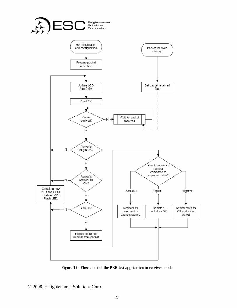
4.4.2 Radio Recepton To prepare for packet reception, the receiving radio configures a DMA channel for transport of incoming data from the radio register RFD to an allocated packet buffer. The DMA is armed and the radio is put to wait for packets. The IRQ_DONE interrupt is enabled and it is triggered on every received packet. When the receiver is

© 2008, Enlightenment Solutions Corp.
17
initialized, it expects a packet with sequence number 1. The received data packet in the allocated packet buffer has to be validated to avoid confusion from interfering traffic at the same frequency. To confirm the validity of the received data packet, its packet length, network ID, CRC and sequence number are verified. Based on the result of the packet verification, one of the following scenarios will occur [4]:
1. The packet length, the network ID, the CRC and the packet’s sequence number are all valid. The expected sequence number of the next received packet is incremented.
2. The packet length, the network ID and the CRC are valid, but the sequence number is not as expected.
a. The received sequence number is less than expected causing the received packet to be considered as a start of a new burst of packets. The next incoming packet is mapped to the received sequence number incremented by 1.
b. The received sequence number is larger than expected. This implies that the received packet is correct, but a number of packets before this one have been lost. The expected sequence number of the next packet is the received sequence number incremented by 1.
3. The packet length and the network ID are valid, but the CRC fails. This implies a corrupted packet is received. The expected sequence number is the received sequence number incremented by 1.
4. The packet length is correct, but the network ID doesn’t match. This received packet is ignored because it comes from an interfering source transmitting packets of the similar length. The expected sequence number is unchanged.
5. The packet length is incorrect. The received packet is ignored and the expected sequence number is unchanged.

© 2008, Enlightenment Solutions Corp.
18
5. Traffic Light Module / LED The traffic light system must be a stand alone unit that maintains operation of a functioning intersection. This system decides which lights are active for each direction of the intersection, as well as the timer to switch direction of traffic flow. Along with the regular traffic light operation, the controller will handle the event of an emergency vehicle approached the intersection. The controller also has to communicate with the RF receiver to receive emergency vehicle information. The traffic light intersection behaviour is built independently of the emergency vehicle communication. This independence is critical because there might not always be a connected module that communicates approaching emergency vehicle information.
5.1 Microcontroller The Cypress CY3681 microcontroller is a low cost option for the traffic light implementation. The EZ-USB FX2 development kit integrates this Intel 8051 based microcontroller with several peripherals and extended memory. This kit even offers a USB connection, which is an uncommon feature. The USB feature will not be utilized for the current ETVC system, having the ability to use it for future development is a strong selling point. The FX2 kit also includes two standard UART serial port connections, which are ideal for vehicle data communication from the RF receiver. Figure 10 demonstrates the transmission of data through the development board.
Figure 10 - Data transfer through the development board The microcontroller used will need to implement the serial port to properly receive vehicle location data. In order to achieve this, the communication settings will need to match the output from the RF receiver (Error! Reference source not found.).

© 2008, Enlightenment Solutions Corp.
19
5.2 Traffic Light Control Algorithm The most important task in the entire EVTC system is a proper functioning set of algorithms that will form a foundation for the operation programming. There needs to be two functions designed in the system. One function maintains the regular operation of the intersection and maximizes traffic flow. The other function handles the event of an emergency vehicles approaching. This function is calculation intensive as the vehicle’s GPS locations will need to be translated into velocity and angle of approach (angles on a compass). If the EMV will reach the intersection in 7 seconds or less, then the traffic lights are changed to allow safe passage for the vehicle. The lights will remain in the emergency state until the vehicle has passed through the intersection (this is done by continuously polling the serial port for update vehicle locations). An important note is that after the timer expires for the regular operation, the ability for the serial port to interrupt the system must be deactivated. If the timer expires and the lights are changing, there cannot be any interruptions to the flow of traffic. Any large disruptions during this period will cause confusion and, potentially, an accident. Figure 11 - Regular operation of the traffic lightFigure 11 and Figure 12 demonstrate the sequence of operations that take place during regular and emergency situations.

© 2008, Enlightenment Solutions Corp.
20
Figure 11 - Regular operation of the traffic light

© 2008, Enlightenment Solutions Corp.
21
Figure 12 - Operation during EMV approaching intersection

© 2008, Enlightenment Solutions Corp.
22
5.3 Traffic light Simulation
5.3.1 LED lights To simulate the traffic light signals we have used LEDs (Light Emitting Diode). LED light provides several advantages over the incandescent lamps. LED offers:
1. Energy efficiency 2. Long life 3. Durability and reliability 4. Small size and design flexibility
The LEDs should be bright enough to be visible from at least 20 meters away with well distinguished colours to avoid confusion. Thus, a super bright 3mm LED having a luminous intensity of 1000 mcd or above is adopted. Also, the viewing angle must be large enough so that luminous intensity will not be affected when viewed from sides. Hence, having a viewing angle greater than 15 degrees will maintain its LED intensity as the driver approaches the light at an angle. Typical values for the LEDs are given as follows:
Part Pkg. colour Lumin.
Intensity(mcd)Forward
voltage (V) Driving
Current (mA) Viewing
angle 55-535SB-1 3mm Green 3400 3.6-4.0 20 mA 15 55-532SB-5 3mm Red 1500 1.8-2.4 20 mA 30 55-534SB-5 3mm Yellow 1200 1.8-2.1 40 mA 15
Table 8 – Typical values of the LED used for traffic light
5.3.2 Schematic Each of the LEDs will be individually controlled by the PORTA and PORTB pin-outs from FX2. There are total of 12 LEDs at the intersection; 4 red, 4 yellow, and 4 green. We cannot directly use the I/O pins from the FX2 to power the LED due to the pin’s output limit. Thus, another voltage source should be used to drive the LEDs. A 9V battery is the perfect candidate source because not only it makes the LED circuits standalone from the FX2, it is also well above the LED voltage for reliable, stable LED operation. It also makes standard ±5% ¼ watt resistor values much more straightforward to choose.

© 2008, Enlightenment Solutions Corp.
23
A simple schematic diagram describing the LED driver is shown as:
Figure 13 - LED circuits for the red, green, and yellow colour in the north direction
N_RED indicates the assigned output pin from FX2 and it is connected to the base of a transistor. The transistor acts as a switch and it operates in saturation mode. It turns on whenever N_RED is raised and turns off otherwise. There are 12 more circuits like this, one for each colour in the North, East, South, and West direction. Only one colour will be turned on at a time for each direction, four 9V batteries will be required in total to ensure sufficient voltage drop across the LEDs. Because LED lights will be positioned under all weather conditions, the circuits will be covered by a waterproof case with a clear cover.

© 2008, Enlightenment Solutions Corp.
24
6. System Test Plan The test plan is composed of two major parts. A comprehensive unit test will be performed on individual modules until all requirements in hardware and software are both satisfied. After unit test completes, an Integration test will be performed to validate and verify the overall system’s proof-of-concept. All individual modules will be connected to a laboratory power supply during unit test. Thus, proper equipment usage and safety checks will be performed prior to developing the prototype.
6.1 GPS Module Performance Testing The GPS module ZX4120 will be tested against other handheld GPS devices such as a Blackberry Curve 8330 and an iPhone, which has standard GPS data built in. Basic navigation parameters such as longitude, latitude, and speed can be extracted by connecting ZX4120 to a laptop via standard RS232 serial cable. The laptop utilizes a hyperterminal program to allow such data extraction from the GPS module. After data is displayed by the hyperterminal, longitude and latitude information will be readily available for comparison with other handheld GPS devices. A nominal reacquisition of GPS is rated at 0.1 second interval. However, it takes an average of one second for the information to be displayed by the hyperterminal. Hence, to test the speed parameter of the GPS there will be different test runs. First, The EMV must be operating at a constant speed starting from 0 km/hour to a maximum of 80 km/hour at 10 km/hour interval, with transition time less than 10 seconds. The next part is to have the EMV accelerate steadily from 0 km/hour to 80 km/hour in 30 seconds. A stop watch or similar device will be used to record the time intervals while the speedometer provides the actual vehicle speed. The same set of test runs will be performed but with different GPS devices for result comparison. Time-to-first-fix of the satellite information, including cold start, warm start, and hot start, will be tested and compared against other GPS devices as mentioned. A 1.5V back up battery supplies the power to the GPS internal memory, which stores the almanac and the ephemeris data. Hence the battery life will be checked regularly and it has to remain at least 50%. A 3.3V @ 27 mA steady source is expected for the ZX4120 module while the antenna requires at least 15 mA for a stable operation. The power supply must be current limited to no greater than 45 mA in order to provide enough current for both parts without posing any potential damage to the module and the antenna.

© 2008, Enlightenment Solutions Corp.
25
6.2 RF Module Performance Testing The wireless signal integrity and quality of the RF module will be evaluated by the Packet Error Rate (PER) application tool provided by Chipcon. This tool lets the user navigate a menu with presets configure of the main radio parameters such as radio frequency, data rate and number of packets to transmit. The packet error rate test will also be able to show accumulated PER and instantaneous Received Signal Strength Indicator (RSSI) values. Because a CRC16 checksum is included in every packet sent by the RF transceiver, this makes it possible for the receiver to detect any bit error and corruption. Security breach will be tested by utilizing a separate RF transceiver module, simulating an anonymous breach. The range of the RF signal will be tested by using the error rate mentioned above. Error rates will be recorded at every 10 meters interval to a maximum distance that does not exceed the minimal acceptable error rate. If the traffic control algorithm are tested to be correct but displays an incorrect traffic pattern, alternative transmission scheme will be reconsidered. Consequently, error rate will be readjusted to reflect the change as well. CC1110 operates at a wide supply voltage range (2.0V – 3.6V), consuming a current of 22 mA to 31 mA with the microcontroller running at 26 MHz. These must parameters will be tested prior to integration with the GPS module to avoid any damage to the pins at either side. A flow chart diagram describing the PER test in transmitter and receiver mode is provided in the following:

© 2008, Enlightenment Solutions Corp.
26
Figure 14 - Flow chart of the PER test application in transmitter mode
© 2008, Enlightenment Solutions Corp.
27
Figure 15 - Flow chart of the PER test application in receiver mode

© 2008, Enlightenment Solutions Corp.
28
6.3 LED lights The EMV driver must be able to see the LED lights from at least 20 meters away in a straight line and at a maximum of 15 degree viewing angle. As well as being able to differentiate the colours at the same distance. To maintain a constant luminous intensity through out all LEDs, The 9V battery powering the LED circuits will be checked at the beginning of every operation to ensure at least 50% of battery life remains. The resistor wattage must be carefully checked to ensure a stable LED operation. For each LED circuit, the resistor wattage will be calculated by multiplying LED voltage drop by its current. No greater than 60 percent of the wattage rating of the resistor should be exceeded. This will ensure the transistor operates in a stable switch in saturation mode with collector current less than 100 mA, which is the absolute maximum rating for a typical 2N3904 transistor. The base cut off current for the transistor will be carefully measured as well. At switch off mode, the base current shall not exceed a maximum of 50 nA. 100 mA is the absolute maximum rating when operating in saturation mode at the base.
6.4 CY3681 for Traffic control Upon receiving the interrupt by the RF board at the intersection, the CY3681 microcontroller must able to properly determine a correct traffic light pattern based on the data received. To test this, a test code simulating an EMV traveling from different direction and speed will be programmed at the RF transceiver and sent to the FX2 board for evaluation. A log recording all test cases will be used to keep track all actual results, and then later compared with the correct one. An internal clock will be implemented to keep track of the total running time. This measurement should be kept within two seconds or less to minimize delay. The FX2’s connection will be subjected to voltage and current supply tests. Output voltage will be verified to be approximately 3.3V while current supply should be no more than 30mA. I/O pins should be checked and kept under this limit as well.
6.5 Integration Test During integration stage, all modules will be powered by either a 9V or AA batteries instead of laboratory power supply. Therefore, all battery power will be checked and must remain at least 50% or greater.

© 2008, Enlightenment Solutions Corp.
29
The EVTC system must be activated when the EMV is no less than 100 meters away from the intersection, hence a traffic cone will be placed at this distance as an indicator. As The EMV passes this marker, EVTC system must be activated immediately for minimal delay in traffic light change. The delay between the start of activation to a successful traffic light change will be measured, which should not exceed a maximum of six seconds. Four seconds for the actual change in the traffic lights and two seconds for EVTC’s decision. The size of the intersection will be varied as well. Intersections in crowded cities and municipalities usually consist of an average of four to six lanes in each direction, with each lane being an average of 3.5 meters in width. Hence, to simulate a large intersection, a minimum of 21 meters in width will be laid out at test track. For a small intersection, this width is 14 meters in width. Tests will be carried out under different weather conditions. A log recording all the test metrics will be used as comparison between sunny, cloudy, raining, and snowing weather.

© 2008, Enlightenment Solutions Corp.
30
7. Conclusion Enlightenment Solution Corporation developed the design specifications in order to define the implementation of the functional requirements of Emergency Vehicle Traffic Control (EVTC) System. The goal of ESC is to ensure the design of EVTC system meets all the functional requirements of the proof of concept model through the test plans as described in this document. The proof-of-concept system is in the progress of development and it is targeted to be completed by of December 17, 2008. Furthermore, the final product will be commercialized in one year from the prototype production date.

© 2008, Enlightenment Solutions Corp.
31
8. Sources and References [1] Enlightenment Solutions Corporation, “Functional Specification for the Emergency Vehicle Traffic Control System”, Simon Fraser University, Burnaby, BC, Canada, October 2008. [2] Crownhill Associates, “Interfacing to the ZX4120 GPS Module,” crownhill.co.uk, June 2005. [Online]. Available: http://www.crownhill.co.uk/datasheets/ZX4120%20GPS.pdf [Accessed: October 30, 2008]. [3] Crownhill Associates, “GPS Engine Board,” crownhill.co.uk, January 2004. [Online]. Available: http://www.crownhill.co.uk/datasheets/ZX4120%20GPS.pdf [Accessed: October 30, 2008]. [4] Syvertsen, E, “Packet Error Rate Application Example,” ti.com, April, 2008. [Online]. Available: http://www.ti.com/litv/zip/swrc085a [Accessed: October 1, 2008] [5] Sundet, T, “Using UART in CC111xFx, CC2431x, and CC251xFx,” ti.com, September, 2008. [Online]. Available: http://www.ti.com/litv/pdf/swra222a [Accessed: October 1, 2008] [6] Cisco Systems, Inc., “RF Power Values,” cisco.com, March, 2008. [Online]. Available:http://www.cisco.com/en/US/tech/tk722/tk809/technologies_tech_note09186a00800e90fe.shtml [Accessed: October 28, 2008] [7] Sputnik, Inc., “RF Propagation Basics,” sputnik.com, April, 2008. [Online]. Available: http://www.sputnik.com/docs/rf_propagation_basics.pdf [Accessed: October 28, 2008] [8] Elcard Wireless Systems Oy, “WLAN Link Distance Calculations,” elcard.fi, November, 2006. [Online]. Available: http://www.elcard.fi/range.htm [Accessed: October 28,2008] [9] Reference Designer, “Reference Designer Calculators,” referencedesigner.com, November, 2008. [Online]. Available: http://www.referencedesigner.com/cal/cal_54.php [Accessed: November 2, 2008] [10] Evjen, P, “AN001 SRD regulations for licence free transceiver operation,” ti.com, 2003. [Online], Available: http://focus.ti.com/lit/an/swra090/swra090.pdf [Accessed: October 31, 2008]

© 2008, Enlightenment Solutions Corp.
32
[11] Lunder, T, “CC11xx Setting for FCC 15.247 Solutions,” ti.com, 2007. [Online]. Available: http://focus.ti.com/lit/an/swra123a/swra123a.pdf [Accessed: October 31, 2008] [12] Winncom Technologies Corp., “Wireless Classroom – FCC Rules, Part 15.247,” winncom.com, 2007. [Online]. Available: http://www.winncom.com/classroom.aspx?room=49 [Accessed: October 31, 2008] [13] Cobb, Terry, “LED and applications,” userpages.umbc.edu, September, 2001. [Online]. Available: http://userpages.umbc.edu/~cobb/cobbtxt/led.txt. [Accessed: November 3, 2008]. [14] Lighting Design Lab, “Advantages of using LED,” www.Lightingdesignlab.com. September, 2002. [Online]. Available: http://www.lightingdesignlab.com/articles/LED_fund/led_advant.htm. [Accessed: Nov 3,2008]. [15] Garmin Ltd, “GPS Definitions,” www8.garmin.com, February, 2001. [Online]. Available: http://www8.garmin.com/aboutGPS/glossary.html. [Accessed: Nov 3, 2008]