design specifications and requirements for a mobile data
TRANSCRIPT

University of Texas at El Paso University of Texas at El Paso
ScholarWorks@UTEP ScholarWorks@UTEP
Open Access Theses & Dissertations
2019-01-01
Design Specifications and Requirements for a Mobile Data Design Specifications and Requirements for a Mobile Data
Acquisition System Acquisition System
Corey Garrett Hansen University of Texas at El Paso
Follow this and additional works at: https://digitalcommons.utep.edu/open_etd
Part of the Aerospace Engineering Commons, and the Mechanical Engineering Commons
Recommended Citation Recommended Citation Hansen, Corey Garrett, "Design Specifications and Requirements for a Mobile Data Acquisition System" (2019). Open Access Theses & Dissertations. 2863. https://digitalcommons.utep.edu/open_etd/2863
This is brought to you for free and open access by ScholarWorks@UTEP. It has been accepted for inclusion in Open Access Theses & Dissertations by an authorized administrator of ScholarWorks@UTEP. For more information, please contact [email protected].

DESIGN SPECIFICATIONS AND REQUIREMENTS FOR A MOBILE DATA
ACQUISITION SYSTEM
COREY GARRETT HANSEN
Master’s Program in Mechanical Engineering
APPROVED:
Jack Chessa, Ph.D., Chair
Ahsan Choudhuri, Ph.D.
Luis Rene Contreras, Ph.D.
Stephen L. Crites, Jr., Ph.D.
Dean of the Graduate School

Copyright ©
by
Corey Hansen
2019

Dedication
I would like to thank my Mom and Dad, first and foremost, for supporting me in everything I do.
I would not have made it this far without y’all. Second, I’d like to thank my girlfriend for helping
to keep me motivated when school or work got tough. Lastly, I’d like to thank all my friends and
colleagues who suffered through the hard times and enjoyed the good times alongside me.

DESIGN SPECIFICATIONS AND REQUIREMENTS FOR A MOBILE DATA
ACQUISITION SYSTEM
by
COREY GARRETT HANSEN, B.S.
THESIS
Presented to the Faculty of the Graduate School of
The University of Texas at El Paso
in Partial Fulfillment
of the Requirements
for the Degree of
MASTER OF SCIENCE
Department of Mechanical Engineering
THE UNIVERSITY OF TEXAS AT EL PASO
December 2019

v
Acknowledgements
To Jack Chessa, Ph.D., Ahsan Choudhuri, Ph.D., Luz Bugarin, Gloria Salas, Charles Hill,
Jason Adams, Marissa Garcia, Marianna Chaidez, Adrian Welsh, Ray Rojo, Rene Miranda, Jerry
Ramirez, and so many others for their help and support in getting the MICIT up and running.

vi
Abstract
This Thesis will discuss the design, use, and maintenance of the Mobile Instrumentation
and Control Interface Trailer (MICIT) housed at tRIAc HQ in Fabens, TX. The design of the
MICIT, as it pertains to this thesis, reflects the “as-built” configuration, which, in some cases,
strays significantly from the original design. These design changes are noted in detail, as are the
reasons for the changes. Appendix A contains a BOM complete with vendor information, part
numbers, and prices where available. Appendix A is provided in an attempt to streamline the
repair/replacement/expansion process for the components in the MICIT. Original AutoCAD
schematics are available in the MICIT schematic library on the SVN.
As a continuation of the “future work” proposed in the original design thesis (Chaparro
2017), the design intent behind each sub-assembly is outside the scope of this thesis, but may be
referenced in some sections. Design intent for new or largely altered sub-assemblies will be
addressed. The LabVIEW, or software interface, side of the MICIT is outside the scope of this
thesis, as it was recently covered by another publication (Rojo, 2019)
Future work proposed in this publication includes compartmentalizing each sub-assembly
and re-termination of system harnessing. Compartmentalization is intended to ease the burden of
troubleshooting and verifying sub-assembly functionality. Re-termination is intended to ease the
daily set-up and tear-down burden on research assistants, technicians, and laboratory personnel.

vii
Table of Contents
Dedication ................................................................................................................................. iii
Acknowledgements ..................................................................................................................... v
Abstract ..................................................................................................................................... vi
Table of Contents ......................................................................................................................vii
List of Tables ............................................................................................................................. ix
List of Figures ............................................................................................................................. x
List of Illustrations ..................................................................................................................... xi
Chapter 1: MICIT Development and Evolution ........................................................................... 1
MICIT Description and Organization Scheme .................................................................... 1
MICIT Layout .................................................................................................................... 3
Chapter 2: MICIT Sub-Assemblies.............................................................................................. 5
MICIT-L1: Motor Valve Panel ........................................................................................... 5
MICIT-L2: Igniter Panel..................................................................................................... 6
MICIT-L3: 120V AC Solenoid Valve Panel ....................................................................... 7
MICIT -L4: 120V AC Solenoid Valves Cont’d................................................................... 8
MICIT-L5: 12V DC Solenoid Valve Panel ......................................................................... 9
MICIT-L6: 12V DC Solenoid Valve Cont’d ..................................................................... 10
MICIT-L7: Warning Lights and Bell ................................................................................ 11
Power Supply Sub-assembly............................................................................................. 12
Trailer Warning Lights and Bell ....................................................................................... 13
MICIT-R1: Cryo PT’s, Differential PT’s, and Turbine Flow Meters ................................. 15
MICIT-R2: Load Cells ..................................................................................................... 16
MICIT-R3: Venturi Flow Meters ...................................................................................... 17
MICIT-R4: Single Ended Static PTs ................................................................................. 18
MICIT-R5: High Speed Instrumentation ........................................................................... 19
MICIT-R6: Unused BNC Connectors ............................................................................... 20
MICIT-R7: K-Type Thermocouples ................................................................................. 20
MICIT-R8: E-Type Thermocouples .................................................................................. 22

viii
MICIT-R9: Communications Panel .................................................................................. 23
Emergency Stop Button .................................................................................................... 23
Chapter 3: Component Specifications ........................................................................................ 24
UPS: APC Model Number SMT1500RM2U .................................................................... 24
8VDC Power Supply: Acopian Model Number A8MT500 .............................................. 28
Relay Card: Omega Model Number OME-DB-24PRD/24/DIN ........................................ 29
Cryo PT Amplifiers – Omega DP25B-E-A ....................................................................... 30
NI cRIO-9066: Control System ........................................................................................ 32
NI cDAQ-9189: Data Acquisition System ........................................................................ 34
NI Module Specifications ................................................................................................. 36
NI9344 .................................................................................................................... 36
NI9403 .................................................................................................................... 37
NI9269 .................................................................................................................... 38
NI9214 .................................................................................................................... 39
NI9205 .................................................................................................................... 40
NI9361 .................................................................................................................... 41
Chapter 4: Current System Advantages and Limitations ............................................................ 43
Current System ................................................................................................................. 43
Future Work ..................................................................................................................... 43
References ................................................................................................................................ 47
Glossary .................................................................................................................................... 48
Appendix A............................................................................................................................... 52
Appendix B ............................................................................................................................... 55
Vita 56

ix
List of Tables
Table 3.1: UPS Output Specifications ....................................................................................... 24 Table 3.2: UPS Input Specifications .......................................................................................... 24
Table 3.3: UPS Battery Specifications ....................................................................................... 25 Table 3.4: UPS Unit Specifications ........................................................................................... 27
Table 3.5: UPS Unit Specifications ........................................................................................... 28 Table 3.6: Relay Card Specifications ......................................................................................... 29
Table 3.7: Baseline Cryo PT Amp Configuration ...................................................................... 30 Table 3.8: DP25B-E-A Specifications ....................................................................................... 31
Table 3.9: cRIO Specifications .................................................................................................. 33 Table 3.10: cRIO Slot Population .............................................................................................. 33
Table 3.11: cDAQ Specifications .............................................................................................. 35 Table 3.12: cDAQ Slot Population ............................................................................................ 35
Table 3.13: NI9344 Specifications ............................................................................................ 36 Table 3.14: NI9403 Specifications ............................................................................................ 37
Table 3.15: NI9269 Specifications ............................................................................................ 38 Table 3.16: NI9214 Specifications ............................................................................................ 39
Table 3.17: NI9205 Specifications ............................................................................................ 40 Table 3.18: NI9361 Specifications ............................................................................................ 41

x
List of Figures
Figure 1.1: Front Panel Layout ....................................................................................................3 Figure 1.2: Back End Layout .......................................................................................................4
Figure 2.1: MICIT-L1 Photo .......................................................................................................5 Figure 2.2: MICIT-L2 Photo .......................................................................................................6
Figure 2.3: MICIT-L3 Photo .......................................................................................................7 Figure 2.4: MICIT-L4 Photo .......................................................................................................8
Figure 2.5: MICIT-L5 Photo .......................................................................................................9 Figure 2.6: MICIT-L6 Photo ..................................................................................................... 10
Figure 2.7: MICIT-L7 Photo ..................................................................................................... 11 Figure 2.8: Power Supply Sub-Assembly Photo ........................................................................ 12
Figure 2.9: Trailer Warning Lights and Bell .............................................................................. 13 Figure 2.10: MICIT-R1 Photo ................................................................................................... 15
Figure 2.11: MICIT-R2 Photo ................................................................................................... 16 Figure 2.12: Original MICIT-R3 Photo ..................................................................................... 17
Figure 2.13: Current MICIT-R3 Photo ...................................................................................... 18 Figure 2.14: MICIT-R4 Photo ................................................................................................... 18
Figure 2.15: MICIT-R5 Photo ................................................................................................... 19 Figure 2.16: MICIT-R6 Photo ................................................................................................... 20
Figure 2.17: MICIT-R7 Photo ................................................................................................... 20 Figure 2.18: MICIT-R8 Photo ................................................................................................... 22
Figure 2.19: MICIT-R9 Photo ................................................................................................... 23 Figure 2.20: Emergency Stop Button Photo ............................................................................... 23
Figure 3.1: UPS Photo ............................................................................................................... 24 Figure 3.2: UPS Runtime Graph ................................................................................................ 26
Figure 3.3: UPS Efficiency Graph ............................................................................................. 27 Figure 3.4: 8VDC Power Supply Photo ..................................................................................... 28
Figure 3.5: Relay Card Photo .................................................................................................... 29 Figure 3.6: Cryo PT Amplifier Panel ......................................................................................... 30
Figure 3.7: cRIO Photo ............................................................................................................. 32 Figure 3.8 cDAQ Photo ............................................................................................................. 34
Figure 3.9: NI9344 Drawing ..................................................................................................... 36 Figure 3.10: NI9403 Photo ........................................................................................................ 37
Figure 3.11: NI9269 Photo ........................................................................................................ 38 Figure 3.12: NI9214 Photo ........................................................................................................ 39
Figure 3.13: NI9205 Photo ........................................................................................................ 40 Figure 3.14: NI9361 Photo ........................................................................................................ 41
Figure A1: NEMA 5-15 Picture................................................................................................. 55

xi
List of Illustrations
Illustration 2.2: MICIT-L2 Schematic .........................................................................................6 Illustration 2.3: MICIT-L2 Schematic .........................................................................................7
Illustration 2.4: MICIT-L4 Schematic .........................................................................................8 Illustration 2.5: MICIT-L5 Schematic .........................................................................................9
Illustration 2.6: MICIT-L6 Schematic ....................................................................................... 10 Illustration 2.7: MICIT-L7 Schematic ....................................................................................... 11
Illustration 2.8: Power Supply Sub-Assembly Schematic........................................................... 12 Illustration 2.9: Trailer Warning Lights and Bell Schematic ...................................................... 14
Illustration 2.10: MICIT-R1 Schematic ..................................................................................... 15 Illustration 2.11: MICIT-R2 Schematic ..................................................................................... 17
Illustration 2.12: MICIT-R4 Schematic ..................................................................................... 19 Illustration 2.13: MICIT-R5 Schematic ..................................................................................... 20
Illustration 2.14: MICIT-R7 Schematic ..................................................................................... 21 Illustration 2.15: MICIT-R8 Schematic ..................................................................................... 22
Illustration 3.1: cRIO Slot Population ........................................................................................ 32 Illustration 3.2: cDAQ Slot Population ...................................................................................... 34

1
Chapter 1: MICIT Development and Evolution
Data acquisition is an integral part of any hardware testing operation. This requires both a
hardware and software component. The Mobile Instrumentation and Control Interface Trailer, or
MICIT for short, is the hardware side of the data acquisition scheme developed for use with the
LO2/LCH4 projects at tRIAc HQ in Fabens, TX. The main objective of MICIT development is to
provide an expandable one-size-fits-all solution for data acquisition with the LO2/LCH4 projects.
Historically, these projects have each used their own custom developed hardware and software
solutions which make data verification, system maintenance, and system operation procedures
very unique to the individual project. By developing a universal hardware and software solution,
we hope to decrease the learning curve associated with starting work on a project/switching
between LO2/LCH4 projects at tRIAc HQ. This decreased learning curve is important, as there is
an inherent high turnover rate in the academic research environment as compared to the research
and development that goes on in industry. Industry side projects can span decades with largely
the same engineering team, so six months to a year of training on a given system isn’t a deal
breaker. Students working on an academic research projects, in contrast, spend two to six years
on average working at the research center, and much of that time is spent on multiple projects.
By easing the transfer into a new project, at least from a data collection standpoint, the MICIT
project helps to increase researcher productivity in the academic environment.
MICIT DESCRIPTION AND ORGANIZATION SCHEME
The main objective of MICIT development is to create a data acquisition system which is
independent of the experiment for which data is being collected. Rocket engine tests, heat transfer
characterization tests, fluid delivery system tests, and many other experiments share similar
requirements in terms of the data that needs to be collected during the test. This commonality is

2
what drove the idea behind the MICIT. While a data acquisition system with as much hardware
support as the MICIT is by no means the lowest cost plan, the single-experiment DAQ systems
that have conventionally been used at cSTER quickly become more expensive when considered
as a whole. The MICIT system allows one cRIO and cDAQ to interface with many different
experiments, which leads to less hardware duplication across the center as a whole – saving money
overall.
The clusters of components that make up the MICIT have been divided into subsystems
based on the harness interface panel that they feed on the front side of the server racks. MICIT
subsystems were named according to a hierarchical scheme beginning with the system name and
followed by the server rack identifier, panel identifier, connection identifier, and pin identifier. By
chaining the identifiers in descending order, a user or technician can refer to any component or
group of components with whatever level of generality or specificity the task at hand requires. As
an example, a user could refer in general to the entire K-Type TC subsystem as MICIT-R7, or go
all the way down to the single positive lead in the 6th K-Type TC by specifying MICIT-R7_6_+.
This scheme allows for connectors with many pins to be easily addressed. MICIT-L1_2, for
example, is the entire DB9 connector on the left-hand side of the MICIT-L1 panel and MICIT-
L1_2_9 is the 9th pin in the MICIT-L1_2 connector. The cRIO, cDAQ, and assorted hardware on
the backend side of the racks follow a similar naming scheme starting with the highest-level
component, usually a cRIO or cDAQ, and ending with the module and module connection
identifiers. The drawings discussed in Chapter 2 follow this same naming scheme.

3
MICIT LAYOUT
There are two main racks in the MICIT system. They are designated MICIT-L and MICIT-
R. MICIT-L houses most of the power distribution and valve interface hardware, including the
motor valve sub-assembly, the igniter sub-assembly, and all 4 of the solenoid valve sub-
assemblies. MICIT-R houses most of the data acquisition hardware, including the cryo PT sub-
assembly, the differential PT sub-assembly, the turbine flow meter sub-assembly, the load cell
sub-assembly, the static PT sub-assembly, the high speed instrumentation sub-assembly, the K-
Type sub-assembly, the E-Type sub-assembly, and the communication sub-assembly. The power
and data systems are in separate racks to limit the amount of electrical noise that the power system
can induce in the data system.
Figure 1.1: Front Panel Layout

4
Figure 1.2: Back End Layout

5
Chapter 2: MICIT Sub-Assemblies
The sub-assemblies described in this chapter serve as the connection point between the test
hardware and the LabView control and acquisition software. As of the writing of this document,
the sub-assemblies share power sources, and a few subassembly panels share modules in the cRIO
and cDAQ. This isn’t the most modular solution, but it does allow for the greatest level of hardware
use as nearly every NI module is wired to capacity. The merits and shortcomings of this solution
will be discussed in detail in Chapter 4.
The current configuration of the sub-assemblies within the MICIT is laid out in support of
the 500lb and RCE test programs. Additional functionality can be added in support of other
projects, if needed in the future. Removal or modification of existing sub-assemblies in order to
support new programs is discouraged, as doing so may negatively impact the MICIT system’s
ability to support existing testing programs. The MICIT shall maintain support for existing
programs until such a time as the program(s) in question have reached end of life and have been
discontinued.
MICIT-L1: MOTOR VALVE PANEL
Figure 2.1: MICIT-L1 Photo
The MICIT-L1 Panel, shown in Figure 2.1, is tailored more for the 500lb engine test than
many of the other MICIT system panels because of the wiring requirements for the motors that set
the position of the main valves. This panel accommodates two motor valves and is broken into two
connector clusters accordingly; one made up of MICIT-L1_1 and -L1_2, and the other of -L1_3
and 4. -L1_1 is a standard banana plug pair which provides 24VDC power from FPS-T1U_1 to

6
the motor valve, and -L1_2 is a DB9 which provides analog and digital communication with the
motor controller. Together, -L1_1 and -L1_2 provide support for a single motor valve. Support for
the second motor valve is provided in the second cluster on the panel, which is set up the same
way as the first. The tailored nature of the MICIT-L1 panel showcases the flexibility in the design
of the MICIT system, wherein each panel can be set up as a general use panel or in support of a
specific subsystem.1
MICIT-L2: IGNITER PANEL
Figure 2.2: MICIT-L2 Photo
Illustration 2.2: MICIT-L2 Schematic
1Moving forward, use of the unique system support panel configuration is discouraged. See NOTE 1 in Appendix A
for more information.

7
The MICIT-L2 panel, shown in Figure 2.2, has capacity for four igniters, however as of
the writing of this report, only two are wired and operational as shown in Illustration 2.2. Each
connector cluster on the panel is made up of 3 connectors; a single BNC connector and a banana
plug pair. The BNC connector supplies the trigger frequency from the signal generator module
(NI9269-1) to the igniter coil pack out at the test article. Signal frequency can be set through
LabVIEW. The banana plug pair provides 8VDC power from the A8MT500 to the coil pack at the
test article.
MICIT-L3: 120V AC SOLENOID VALVE PANEL
Figure 2.3: MICIT-L3 Photo
Illustration 2.3: MICIT-L2 Schematic
The MICIT-L3 panel, shown in Figure 2.3, contains 16 banana plug pairs. These banana
plug pairs are set up in a high side switch configuration, wherein the hot leg of the 120V AC

8
facility power is fed through a relay in the 3rd relay board (OME-DB-24PRD/24/DIN – 3) before
running to the positive (red) banana plug connector. The neutral leg of the 120V AC facility power
runs to the negative (black) banana plug connector. This connection method ensures that until the
relay is powered on through LabView, the positive banana plug connection is not powered. While
the alternative connection method (known as a low-side switch) would cycle the valve in the same
way once it was connected, a low-side switch configuration would leave the positive banana plug
connection energized when an SV is not plugged in, which presents a safety hazard for personnel
interacting with the panel.
MICIT -L4: 120V AC SOLENOID VALVES CONT’D
Figure 2.4: MICIT-L4 Photo
Illustration 2.4: MICIT-L4 Schematic
The MICIT-L4 panel, shown in Figure 2.4, contains 16 banana plug pairs in much the same
configuration as those in MICIT-L3, with the only exception being that the connections are split

9
between relay boards 2 and 3 (OME-DB-24PRD/24/DIN – 2 and OME-DB-24PRD/24/DIN – 3,
respectively) as shown in Illustration 2.4. MICIT-L4 is connected in the same high-side switch
configuration as MICIT-L3.
MICIT-L5: 12V DC SOLENOID VALVE PANEL
Figure 2.5: MICIT-L5 Photo
Illustration 2.5: MICIT-L5 Schematic
The MICIT-L5 panel, shown in Figure 2.5, contains 16 banana plug pairs in much the same
configuration as the 120V AC variants in -L3 and -L4, with two key differences. 1) The power
feeding the high side of the switch comes from the 12 DC power supply (FPS-T1U_2), and 2) the
positive (red) banana plugs are connected to the relays in relay card 1 (OME-DB-24PRD/24/DIN
– 1) as shown in Illustration 2.5.
10
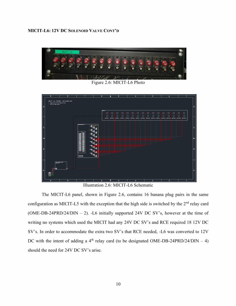
MICIT-L6: 12V DC SOLENOID VALVE CONT’D
Figure 2.6: MICIT-L6 Photo
Illustration 2.6: MICIT-L6 Schematic
The MICIT-L6 panel, shown in Figure 2.6, contains 16 banana plug pairs in the same
configuration as MICIT-L5 with the exception that the high side is switched by the 2nd relay card
(OME-DB-24PRD/24/DIN – 2). -L6 initially supported 24V DC SV’s, however at the time of
writing no systems which used the MICIT had any 24V DC SV’s and RCE required 18 12V DC
SV’s. In order to accommodate the extra two SV’s that RCE needed, -L6 was converted to 12V
DC with the intent of adding a 4th relay card (to be designated OME-DB-24PRD/24/DIN – 4)
should the need for 24V DC SV’s arise.

11
MICIT-L7: WARNING LIGHTS AND BELL
Figure 2.7: MICIT-L7 Photo
Illustration 2.7: MICIT-L7 Schematic
The MICIT-L7 panel, shown in Figure 2.7, supports the trailer warning lights and bell, and
is different from the other interface panels in that its operation is usually internal to the MICIT.
Other panels usually connect to harnessing which interfaces with hardware outside the MICIT, but
-L7’s connection routs back into the bell and lights on the trailer. The connections were left
accessible on the front panel, as it may be advantageous to connect auxiliary lights to these same
connections to allow for remote warning lights to be placed away from the MICIT. In the event
that auxiliary warning lights or bells are used, take care to ensure that the total current through any
one relay (read current through any one banana plug pair) does not exceed the relay card’s stated
switching current of 5A@30VDC. The bell’s hookup location is labelled “Buzzer” as the MICIT

12
was originally slated to have a buzzer type audible indicator, however the buzzer was not loud
enough at a distance and was switched over to a fire alarm bell.
POWER SUPPLY SUB-ASSEMBLY
Figure 2.8: Power Supply Sub-Assembly Photo
Illustration 2.8: Power Supply Sub-Assembly Schematic

13
The Power Supply Subsystem, Shown in Figure 2.8, consists of the SMT1500RM2 UPS,
A8MT500 power supply module, and the FPS-T1U rack mount power supply unit. The A8MT500
has an input of 105-125VAC and an output of up to 5A at 8V DC. The FPS-T1U has an input of
85-250VAC. FPS-T1U_1 has an output of 21.5-29VDC at a maximum of 40A. FPS-T1U_2 has
an output of 10.5-13.2VDC at a maximum of 72A. This system supplies power to all the
instrumentation in the MICIT system. Future work includes migrating the 120VAC SV power
source from the UPS to a separate 120VAC power assembly to reduce demand on the UPS and
increase battery based operating time.
TRAILER WARNING LIGHTS AND BELL
Figure 2.9: Trailer Warning Lights and Bell

14
Illustration 2.9: Trailer Warning Lights and Bell Schematic
The MICIT is equipped with three warning lights and a bell as safety measures. By
triggering the green, amber, or red lights the operator is able to inform others visually and from a
distance as to what the status of the MICIT is. The lights flash on their own, and as such the
operator can only turn them on or off; the color is the only indicator of system status. Speed and
pattern of flashing is not determined by the operator and does not have a set meaning. The warning
bell serves as an audible alert to catch the attention of anyone not in visual range of the lights, and
is to be activated before any test goes active. The operator is able to control the duration and pattern
of bell activation through LabView, which allows for several different audible alarms.
The lights and bell are to be connected to MICIT-L7, with red connected to -L7_1, amber
to -L7_2, green to -L7_3, and the bell to -L7_4 as shown in Illustration 2.9. The lights have a
nominal input of 12 V DC and pulls 2.8A each when active. The bell has a nominal input of 12 V
DC and pulls 0.45A when active. Connection paths are explained in detail in the MICIT-L7 Panel
section.

15
MICIT-R1: CRYO PT’S, DIFFERENTIAL PT’S, AND TURBINE FLOW METERS
Figure 2.10: MICIT-R1 Photo
Illustration 2.10: MICIT-R1 Schematic
The MICIT-R1 panel is different than most other panels in that it houses multiple
subsystems. -R1’s front interface consists of a 3U panel, and the 3 subsystems installed in this
panel are separated by row. All connections in this panel use 4-pin speaker connectors, however

16
each row is wired differently due to the different sensor requirements, so care must be taken to
ensure that instruments do not get cross connected or connected to the wrong places. Connections
in this panel share the same connector type, as it was not economically viable to source enough
distinct connectors to prevent cross connection.
The first row (-R1_1 through -R1_12) is designated MICIT-R1_A and houses connections
for Omega PX1005 Series Cryo PTs. The sensor model is important in this row because each plug
is wired to provide the input power (24VDC from FPS-T1U_1) the PX1005 requires, and to
amplify the output voltage of the PX1005 through the bank of DP25B-E-A amplifiers and
ultimately back to NI9205-3. Different sensors may have different inputs and outputs, and may or
may not need to be amplified, thus it is imperative that these parameters be checked if different
instrumentation is to be used in this first row.
The second row (-R1_13 and _14) is designated as MICIT-R1_B and houses connections
for Stellar Technologies DT1400-30BD-233 differential PTs. At the time of writing, these PTs are
only used on the 500lb test stand, and there are only 2 of them, which is why -R1_13 and _14 are
the only two wired connections in this row. If more DT1400s are added in the future, or if another
system uses more of them, connectors can be added to this row to accommodate. The DT1400s
take a 14 to 32VDC input and output 0-5VDC, and the connectors are wired accordingly, with
power coming from FPS-T1U_1, and the differential signal feeding into NI9205-3.
The third row (-R1_25 through _32) is designated as MICIT-R1_C and houses connections
for COX CLF6AN turbine flow meters. This panel supports 8 turbine flow meters. Each connector
is wired to provide power (24VDC) from FPS-T1U_1 and to send the signal returned from the
instrument to NI9361_1.
MICIT-R2: LOAD CELLS
Figure 2.11: MICIT-R2 Photo

17
Illustration 2.11: MICIT-R2 Schematic
The MICIT-R2 panel is intended to house connections for PCB Piezotronics brand load
cells, but as of writing, the load cells are not in use in any test article and have not been incorporated
into the system. Each connector in this panel is a DB9, with pins 1-4 wired to supply power and
receive signal from the load cell. Illustration 2.11 shows the wiring that is planned should these
load cells come into use.
MICIT-R3: VENTURI FLOW METERS
Figure 2.12: Original MICIT-R3 Photo

18
Figure 2.13: Current MICIT-R3 Photo
The MICIT-R3 panel originally housed connectors for the two venturi flow meters (as
shown in Figure 2.12) on the 500lb test stand. Each connector cluster consisted of a standard cryo
PT, a differential PT, and an E-type TC connector, which are each already housed in other panels.
The PT connectors were moved to MICIT-R1. The E-type TCs were moved to MICIT-R8. See
NOTE 1 in Appendix A for details. The location is currently occupied by a blank panel (as shown
in Figure 2.13), and is available for future expansion.
MICIT-R4: SINGLE ENDED STATIC PTS
Figure 2.14: MICIT-R4 Photo

19
Illustration 2.12: MICIT-R4 Schematic
The MICIT-R4 panel houses connections for 22 single ended static pressure transducers.
The connection is wired to supply the instrument with 24VDC power and to accept a single 0-
5VDC signal which is routed to NI9205-1 and NI9205-2. The signal is split and transmitted to
both the cDAQ for data acquisition and to the cRIO for use as a redline. The standard PTs were
chosen as redlines, as they do not require amplification or postprocessing like the cryo or
differential PTs do. This leaves less room for error due to calibration, which makes these sensors
better candidates for system critical redline data sources.
MICIT-R5: HIGH SPEED INSTRUMENTATION
Figure 2.15: MICIT-R5 Photo

20
Illustration 2.13: MICIT-R5 Schematic
The MICIT-R5 panel consists of 8 BNC connectors, and is designed to accept signal from
dynamic PTs and accelerometers. The panel connects to the PCB_483C05 signal conditioner
mounted in the top of the MICIT-R rack. As of the writing of this document, MICIT-R5 is wired
and ready, but has remained unused.
MICIT-R6: UNUSED BNC CONNECTORS
Figure 2.16: MICIT-R6 Photo
The MICIT-R6 panel consists of 8 BNC connectors, identical to those in -R5. At the time
of writing, all connectors in -R6 are available for use in future expansion.
MICIT-R7: K-TYPE THERMOCOUPLES
Figure 2.17: MICIT-R7 Photo

21
Illustration 2.14: MICIT-R7 Schematic
The MICIT-R7 panel houses connections for 32 K-Type TCs. MICIT-R7_1 through -
R7_16 are connected to both the cRIO and cDAQ for use as redlines and as data collection sensors.
MICIT-R7_17 through -R7_32 are only connected to the cDAQ and therefore only function as
data collection sensors. K-Type TCs are suitable for measuring temperatures from -454°F to
+2300°F (-270°C to 1260°C) with higher accuracy at the top end of the operating range. K-Type
TCs are commonly used to monitor high temperature surfaces such as rocket engine or combustor
chamber surfaces.

22
MICIT-R8: E-TYPE THERMOCOUPLES
Figure 2.18: MICIT-R8 Photo
Illustration 2.15: MICIT-R8 Schematic
The MICIT-R8 panel houses connections for 32 E-Type TCs. All E-Type TCs are
connected to the cDAQ and only function as data collection sensors. E-Type TCs are suitable for
measuring temperatures from -454°F to +1600°F (-270°C to +870°C) with higher accuracy at the
low end of the operating range. E-Type TCs are commonly used to monitor low temperature
surfaces or fluids such as liquid nitrogen, liquid methane, and liquid oxygen delivery lines.

23
MICIT-R9: COMMUNICATIONS PANEL
Figure 2.19: MICIT-R9 Photo
The MICIT-R9 panel houses the fiberoptic connection that allows for communication
between the main control computer and the cRIO and cDAQ in the MICIT. The yellow fiber optic
cable is to be routed through the strain relied bracket (pictured in Figure 2.19) to prevent the weight
of the cable from pulling on the connectors.
EMERGENCY STOP BUTTON
Figure 2.20: Emergency Stop Button Photo
The MICIT system includes an emergency stop button, located in the top frame panel of
the MICIT-R rack. The e-stop button is wired into the cRIO, and functionality is defined in the
LabVIEW VI. The e-stop button is intended to be used as a safety contingency in the event that
personnel are in the MICIT when the system begins hazardous operations.

24
Chapter 3: Component Specifications
This chapter discusses the specifications and usage instructions for many of the
components in the MICIT system. This chapter is intended to make repairs easier by simplifying
the procurement and replacement process.
UPS: APC MODEL NUMBER SMT1500RM2U
Figure 3.1: UPS Photo
The SMT1500RM2U is a 120V AC battery backup by APC which switches power delivery
from mains power to its internal battery pack, without cutting power to the equipment it supplies,
should the mains power cut out.
Table 3.1: UPS Output Specifications
SPECIFICATION VALUE
Output Power Capacity 1000 W
Output Voltage 120VAC (Nominal)
Output Voltage Distortion <5% at full load (114VAC to 126VAC)
Output Frequency 50 to 60Hz +/- 3 Hz (Auto Sync to mains)
Output Connections 6 (NEMA5-15R)
Surge Protection Rating 459 Joules
Table 3.2: UPS Input Specifications
SPECIFICATION VALUE
Transfer Time (Mains to Battery) 4ms typ : 8ms max
Input Voltage 120VAC (Nominal)
Input Voltage Range 82 to 144V

25
Input Frequency 50 to 60Hz
Input Connection 1 (NEMA 5-15P)
Cord Length 8’ (2.44m)
Table 3.3: UPS Battery Specifications
SPECIFICATION VALUE
Battery Type Leak Proof Sealed Lead-Acid w/ suspended
electrolyte
Typical Recharge Time 3 hr
Expected Battery Life 3 to 5 yr
Battery Volt-Amp-Hour Capacity 432
Net Weight 26.32 lb (11.96 kg)
Operating Temperature +32 to +104 °F (0 to +40 °C)
Operating Humidity 0 to 95%
Operating Elevation 0 to 10,000 ft (0 to 3000 m)
Storage Temperature +5 to +13 °F (-15 to +45 °C)
Storage Elevation 0 to 50,000 ft (0 to 15000 m)
Battery Disposal Prepaid postage

26
Figure 3.2: UPS Runtime Graph

27
Figure 3.3: UPS Efficiency Graph
Table 3.4: UPS Unit Specifications
SPECIFICATION VALUE
Audible Alarm Battery supply mode and low-battery alarms
Weight2 63 lb (28.6 kg)
Rack Width 19”
Rack Height 2U
Operating Temperature +32 to +104 °F (0 to +40 °C)
Operating Humidity 0 to 95%
Operating Elevation 0 to 10,000 ft (0 to 3000 m)
Storage Temperature +5 to +113 °F (-15 to +45 °C)
2Due to the unit weight, OSHA recommends the use of two or more people when lifting or moving the unit.

28
Storage Elevation 0 to 50,000 ft (0 to 15000 m)
Noise Level 46.0 dBA @1m
Online Thermal Dissipation 90.0 BTU/hr
8VDC POWER SUPPLY: ACOPIAN MODEL NUMBER A8MT500
Figure 3.4: 8VDC Power Supply Photo
The Acopian A8MT500 is an 8VDC power supply. It takes one 120VAC output from the
APC UPS and converts it to 8VDC power, currently used for the igniters in MICIT-L2.
Table 3.5: UPS Unit Specifications
SPECIFICATION VALUE
Input Voltage Range 105 to 125 VAC
Input Voltage Frequency 50 to 400Hz; Single Phase
Polarity3 Output is floating, positive or negative
terminal may be grounded or floated up to 300
volts above ground.
Temperature Coefficient 0.015%/°C
Ambient Operating Temperature -4 to +159.8 °F (-20 to 71 °C)
Storage Temperature -67 to +185 °F (-55 to +85 °C)
Response Time <20 microseconds
Mounting DIN Rail
3Always connect -8V lines back to the negative terminal on the A8MT500. Negative connected to ground cannot be
assumed to produce an 8VDC delta between positive and negative.

29
Case Size M6
Overvoltage Protection None
RELAY CARD: OMEGA MODEL NUMBER OME-DB-24PRD/24/DIN
Figure 3.5: Relay Card Photo
The OME-DB-24PRD/24/DIN is an Omega relay card with 16 NC relays, and 8 selectable
(NC or NO) relays. There are 3 of them in the system, each connected to its controlling module in
the cRIO by a (DB37) cable.
Table 3.6: Relay Card Specifications
SPECIFICATION VALUE
Control Logic Input TTL High (+5VDC)
Maximum Switching Voltage/Current 250VAC/5A, 30VDC/5A
Number of Channels 24
Ambient Operating Temperature Range +32 to +140 °F (0 to +60 °C)
Storage Temperature Range -4 to +158 °F (-20 to +70 °C)
Relay Response Time 10 ms
Max Power Consumption Voltage/Current 24VDC/0.8A

30
CRYO PT AMPLIFIERS – OMEGA DP25B-E-A
Figure 3.6: Cryo PT Amplifier Panel
The MICIT system currently uses 12 Omega DP25B-E-A units to amplify the signals from
the Omega PX1005 Series pressure transducers. The DP25B-E-A is configurable and can be
calibrated to amplify signals from other instrumentation. Table 3.7 lists the configuration settings
for use with the PX1005 PT. Table 3.8 lists the specifications for the DP25B-E-A.
Table 3.7: Baseline Cryo PT Amp Configuration
GROUP SPECIFICATION VALUE DESCRIPTION
Main Inpt 100M Specifies input range
Main Decp FFFF Specifies the location of the decimal point on the
display.
RDSO In1 0138 Signal from instrumentation at input setpoint 1
RDSO RD1 0014 Reading, in PSI, correlated to In1 (Ambient
pressure PSIA)
RDSO In2 3320 Signal from instrumentation at input setpoint 2
RDSO RD2 PT Max4 Reading, in PSI, correlated to In2 (PT max
pressure PSIA)
4PT Max varies based on the instrumentation used. Configuration should read 1000 for a PT with a 1000 PSI rating,
500 for a 500PSI rating, etc.

31
RDCF R.1 N
RDCF R.2 4
RDCF R.3 F
OTCF O.1 E
OTCF O.2 V Sets the output type to voltage
OTSO RD1 0000 Reading for output setpoint 1
OTSO OUT1 0000 Output correlated to RD1
OTSO RD2 PT Max Reading for output setpoint 2 (Should match RD2
in the RDSO menu)
OTSO OUT2 10 Output correlated to RD2
LkcF Rs E
Table 3.8: DP25B-E-A Specifications
SPECIFICATION VALUE
Display digits 4
Display Colors Red, Amber, Green5
Voltage Output Option 0 to 10V
Current Output Option 4 to 20mA or 0 to 20nA
Read Rate 3/s
Power 115 VAC or 230 VAC ± 10%; 11 W Max; 240
Vrms overvoltage protection
Input Ranges 0 to 100mV; ±50 mV; 0 to 10 V; ±5 V; 0 to 20
mA; 4 to 20 mA
Max Error Strain / Process ±0.03% rdg
Accuracy 0.02% rdg
5Amber and green display colors can not be used concurrently with high display brightness unless connected
instrumentation is on a separate power supply.

32
Span Temperature Coefficient ±50 ppm/°C
Warm-Up Time (to rated accuracy) 30 min
Excitation Voltage Options 24V@25mA; 12V@50mA; 10V@120mA;
5V@60mA
NI CRIO-9066: CONTROL SYSTEM
Figure 3.7: cRIO Photo
Illustration 3.1: cRIO Slot Population
cRIO9066-1 is the control side of the MICIT, and contains modules with a variety of
control and data collection functions. cRIO9066-1 (colloquially known as “the cRIO”) has 8
module slots which are designated cRIO9066-1_1 through _8. Table 3.9 lists the specification the
cRIO9066. Table 3.10 lists the modules which are installed in each slot on the cRIO. In similar
fashion to the connectors within each sub-assembly, the cRIO modules have a dash followed by a
number appended to the model number. This aids in identification of which module is in each sub-
assembly. While a cRIO can be used to collect data, this is limited to redline data to reduce the

33
load on the cRIO and in doing so increase the responsiveness of the system. This minimizes the
time it takes for the system to react to a redline condition, and reduces the change of damage to or
failure of a test article.
Table 3.9: cRIO Specifications
SPECIFICATION6 VALUE
CPU Core Count 2
CPU Speed 667 MHz
DRAM 256 MB
Onboard Storage 512 MB
Operating Temperatures -4°F to +131°F (-20°C to +55°C)
Compatible Software LabVIEW 2014 or later; LabVIEW Real-Time
Module 2014 or later; LabView FPGA Module
2014 or later
Driver Software NI-RIO Device Drivers 14.0 or later
Timing Accuracy 5 ppm
Internal Battery Life (Unit Powered) 10 yr
Internal Battery Life (Unit Unpowered) 5 yr
Internal Battery Replacement Method RMA
Voltage Input Range 9 VDC to 30 VDC
Reverse Voltage Protection 30 VDC Maximum
Maximum Altitude 16404 ft (5000 m)
Weight (Unloaded) 36.97 oz (1048 g)
Sleep Mode Compatible Yes
Table 3.10: cRIO Slot Population
CRIO SLOT MODULE
6Additional Specifications Available in the cRIO9066 Spec Sheet

34
cRIO9066-1_1 NI9344-1
cRIO9066-1_2 NI9403-1
cRIO9066-1_3 NI9403-2
cRIO9066-1_4 NI9403-3
cRIO9066-1_5 NI9269-1
cRIO9066-1_6 NI9214-1
cRIO9066-1_7 N/A
cRIO9066-1_8 NI9205-1
NI CDAQ-9189: DATA ACQUISITION SYSTEM
Figure 3.8 cDAQ Photo
Illustration 3.2: cDAQ Slot Population
cDAQ9189-1 is the data acquisition side of the MICIT, and contains modules with a variety
of data collection functions. cDAQ9189-1 (colloquially referred to as “the cDAQ”) has 8 module
slots which are designated cDAQ9189-1_1 through _8. Table 3.11 lists the specifications of the
cDAQ9189. Table 3.12 lists the modules which are installed in each slot on the cDAQ. In similar

35
fashion to the cRIO modules, the cDAQ modules have a dash followed by a number appended to
the model number. This aids in identification of which module is in each sub-assembly. Large
quantities of incoming data can cause the cDAQ data log to lag behind real time, sometimes
reportedly taking 10 to 15 minutes to finish compiling data once a test has finished.
Table 3.11: cDAQ Specifications
SPECIFICATION7 VALUE
Maximum Sample Rate Determined by modules
Timing Accuracy 50 ppm of sample rate
Input Voltage Protection -20V min; +25V max
Output Voltage Protection -15V min; +20V max
Input Voltage Range 9V to 30V DC
Maximum Power Consumption 16W
Operating Temperature Range -40°F to +158°F (-40°C to +70°C)
Maximum Altitude 16404 ft (5000 m)
Weight (Unloaded) 37.6 oz (1065.9 g)
Sleep Mode Compatible No
Table 3.12: cDAQ Slot Population
CDAQ SLOT MODULE
cDAQ9189-1_1 NI9214-2
cDAQ9189-1_2 NI9214-3
cDAQ9189-1_3 NI9214-4
cDAQ9189-1_4 NI9214-5
cDAQ9189-1_5 NI9205-4
cDAQ9189-1_6 NI9205-2
cDAQ9189-1_7 NI9361-1
7Additional Specifications Available in the cDAQ9189 Spec Sheet.

36
cDAQ9189-8 NI9205-3
NI MODULE SPECIFICATIONS
NI9344
Figure 3.9: NI9344 Drawing
The NI9344 is an IO module with 4 physical input switches and 4 output LEDs. This
module can be used both to collect user input and display that said input has been received.
Table 3.13: NI9344 Specifications
SPECIFICATION VALUE
Operating Temperature Range -40°F to 158°F (-40°C to +70°C)
LED Solid On This channel has been programmed to be in the
on state
LED Off This channel has been programmed to be in the
off state
Digital Input 4 switches
Digital output 4 channels, LEDs
Switch Life Expectancy 50,000 operations
Power Consumption 145 mW max (Active mode); 25 µW (Sleep
Mode)

37
Weight 5.3 oz (150 g)
NI9403
Figure 3.10: NI9403 Photo
The NI9403 is a digital IO module with 32 channels. This module can be used to
communicate with other hardware such as, in the case of the MICIT, a relay control board.
Table 3.14: NI9403 Specifications
SPECIFICATION VALUE
Number of Channels 32
Input/Output Type TTL/single ended
Input Current ±250 µA Maximum from 0 V to 4.5 V
Output Current 64 mA
Input Voltage -0.25 V to 5.25 V
Input High 2.2 V Minimum
Input Low 0.8 V Maximum
Power Consumption 1 W Maximum (Active Mode); 25 µW
Maximum (Sleep Mode)
Channel to COM Safety Voltage No Greater Than ±30 V on up to 8 channels at
a time
Channel to Earth Ground Safety Voltage 60 VDC

38
Operating Temperature -40°F to 158°F (-40°C to +70°C)
NI9269
Figure 3.11: NI9269 Photo
The NI9269 is an analogue output module with a nominal output of ±10V.
Table 3.15: NI9269 Specifications
SPECIFICATION VALUE
Number of Channels 4
Output Range ±10V Nominal; ±10.38 V Min; ±10.47 Typ;
±10.56 Max
Current Drive ±20mA all channels max; 10mA per channel
Overvoltage Protection ±30 V
Short Circuit Protection Indefinitely
Power Consumption 1 W Max (Active Mode); 120 µW (Sleep
Mode)
Weight 5.5 oz (156 g)
Channel to Channel Safety Voltage 250Vrms continuous
Channel to Earth Ground Safety Voltage 250 Vrms Continuous
Operating Temperature -40°F to 158°F (-40°C to +70°C)

39
NI9214
Figure 3.12: NI9214 Photo
The NI9214 is a TC terminal block with capacity for 16 TCs. Figure 3.12 shows the NI9214
with the terminal block (TB-9214). Every NI9214 in the MICIT system is equipped with a TB-
9214.
Table 3.16: NI9214 Specifications
SPECIFICATION VALUE
Number of Channels 16 TC Channels; 1 internal autozero channel; 3 internal
cold-junction compensation channels in TB-9214
Compatible TC Types J, K, T, E, N, B, R, S
Conversion Time 52ms in High Resolution Mode; 735 µs in High Speed
Mode
Sample Rate 1
(𝐶𝑜𝑛𝑣𝑒𝑟𝑠𝑖𝑜𝑛 𝑇𝑖𝑚𝑒 ∗ 𝑁𝑢𝑚𝑏𝑒𝑟 𝑜𝑓 𝐶ℎ𝑎𝑛𝑛𝑒𝑙𝑠 𝑖𝑛 𝑢𝑠𝑒)⁄
or 100 S/s, whichever is smaller.
Warm Up Time 15 min to full rated accuracy
Overvoltage Protection ±30 V between any two inputs
Operating Temperature Range -40°F to 158°F (-40°C to +70°C)

40
Gain Error (Within Operating Temp.
Range)
0.15% Max (High Resolution Mode); 0.16% Max (High
Speed Mode)
Power Consumption 300 mW Max (Active Mode); 30 µW Max (Sleep Mode)
Thermal Dissipation 630 mW Max (Active Mode); 450 mW Max (Sleep
Mode)
Weight 5.0 oz (141 g) for NI9214; 3.6 oz (102 g) for TB-9214
NI9205
Figure 3.13: NI9205 Photo
The NI9205 is an analogue input module with 16 double ended or 32 single ended channels.
It is available win both spring channel and D-Sub variants. The spring terminal variant has the
advantage of being easier to assemble than the D-Sub variant, however the spring terminal variant
is not suited to repeated connect/disconnect cycles. The MICIT currently uses the spring terminal
variant.
Table 3.17: NI9205 Specifications
SPECIFICATION VALUE
Number of Channels 16 differential / 32 single ended
Conversion Time (Max Sample Rate) 4.00 µs (kS/s)
Nominal Input Ranges ±10 V; ±5 V; ±1V; ±0.2 V

41
Max Working Voltage Each Channel Must Stay Within ±10V of
COM
Power Consumption 625 mW (Active Mode); 15 mW (Sleep Mode)
Operating Temperature Range -40°F to 158°F (-40°C to +70°C)
Weight 5.7 oz (163 g) w/ spring terminal
NI9361
Figure 3.14: NI9361 Photo
The NI9361 is a counter module which counts the frequency of a signal. In the MICIT
system, this module is used to count the frequency signal from the RCE turbine flow meters.
Table 3.18: NI9361 Specifications
SPECIFICATION VALUE
Number of Inputs 8
I/O Signal Rate 1 MHz Max
Differential Input Voltage Range 0 V to 5 V
Single Ended Voltage Range 0 V to 24 V
Maximum Input Current 50 µA Max Per Terminal @5V Input; 1.5 mA
Max Per Terminal @ 24 V Input

42
Power Consumption 0.92 W Max (Active Mode); 53 µW Max
(Sleep Mode)
Operating Temperature Range -40°F to 158°F (-40°C to +70°C)
Weight 5.15 oz (146 g)
43
Chapter 4: Current System Advantages and Limitations
CURRENT SYSTEM
The current MICIT system allows for subsystems to share NI Modules in both the cRIO
and cDAQ. This was done to ensure that each module was filled as close to capacity as possible,
as installing duplicates of the same module solely to ease sub-assembly removal and installation
leads to a massive increase in the cost and complexity of the system. This layout works, however
it introduces several problems when troubleshooting a sub-assembly. Without a connector in
between the NI Module and the sub-assembly front panel, modules which share connections with
multiple sub-assemblies cannot be removed for troubleshooting without disconnecting adjacent
sub-assemblies as well. This increases the workload on the technician and introduces sources of
error when reassembling the system after troubleshooting has been completed. The “Box-style”
solution presented in the next section contains mitigation for this ‘multiple disconnect’
complication.
This ‘multiple disconnect’ complication has, at least once, caused a waterfall effect while
troubleshooting, wherein the investigation of a fault in one sub-assembly required disconnection
of another sub-assembly, which in turn introduced a fault in that sub-assembly upon reassembly.
One instance in particular, troubleshooting the connections to the bank of cryo PT amplifiers, led
to the removal and reinstallation of not only the cryo PT connections, but also the differential PTs
which share connections in NI9205-3. Breaking the connections to the NI Modules with a multipin
connector (DB9 or similar) on a sub-assembly basis would mitigate this problem by allowing for
single sub-assembly removal without affecting adjacent hardware.
FUTURE WORK
The current MICIT System meets the requirements set for it, however ease of use for the
people using and troubleshooting the system could be much improved. From an end user
perspective, there are several challenges to easy day to day operations that could be overcome in

44
future work. From a troubleshooting perspective there are several barriers to easy identification of
the problem source.
As an end user, the main barrier to easy use of the system on a day to day basis comes in
the form of cable management and connection. The quantity of instrumentation in any one setup
combined with the mobile nature of the MICIT means that any given test day begins with plugging
in up to 200 individual connectors. This presents an enormous drain on personnel and imparts a
significant delay to the beginning of the test day. One suggested solution is to re-terminate the
harnessing, so that the connection/disconnection point is located at the outer wall of the MICIT
and is accomplished through the use of 48-pin cannon plugs. This strategy would bring that 200-
connection number down to approximately 6, depending on pinout configuration in the cannon
plugs. Thermocouple connections would still need to be made individually, as thermocouple
cannon plugs are prohibitively expensive. The same could be done at the other side of the
harnessing, further reducing the number of man-hours consumed by harnessing set-up. While this
seems like an easy solution, implementation requires several weeks of time from a trained
technician who would be tasked with splicing into the existing harnesses and assembling the
connectors.
As a technician working to troubleshoot a problem and/or verify correct operation of the
system, the main barrier to ease of work presents itself in the complexity of the wiring behind the
front panels. While most sub-assemblies are only connected to one front panel, the wiring in the
rack is not confined to the area behind that panel. Wiring for every sub-assembly shares a sort of
common area in the rack as it makes its way over to the cRIO and cDAQ. This complicates
troubleshooting efforts, as the technician working the problem has to work in cramped conditions
within the rack and must work around the wiring for the other sub-assemblies. All of this must be
done without disturbing the other sub-assembly wiring, so as not to introduce another potential
issue to troubleshoot.
One solution to this problem, and the solution proposed for future work, is to isolate each
sub-assembly to a 1U, 2U, or 3U rack mount ‘box’ that can be pulled out of the system in one

45
piece so that problems may be worked on a lab bench. Take the UPS as an example. Should a
technician or user notice a problem in power delivery when on battery power, one approach could
be to remove the UPS from the rack, which would isolate the work to the UPS alone. A similar
style box, containing all the wiring for a sub-assembly, with a front panel exactly like the ones in
the current setup and a single connector (DB37 or similar) on the back would simplify the
troubleshooting process. The technician could remove the box in question and take it to a bench
where he/she could work the problem without fighting cramped conditions and the wiring from
other sub-assemblies. The technician would also avoid tampering with other subsystems, as
disconnecting from the cRIO or cDAQ at the connector on the box eliminates the need to remove
the NI Module it connects to. This solution also dramatically improves the cable management
situation in the rack, as the large volume of common wiring area would be broken up into discrete
units for each sub-assembly.
Obstacles to implementation of this system presents themselves in the time, money, and
labor required to locate all of these subsystems in rack mount boxes. One way to reduce the cost
would be to remove the existing wiring from the racks, place it into boxes, and then reinstall the
boxes in the racks. This comes with the downside of requiring that the MICIT be offline during
the rework. Another option, which doesn’t require that the MICIT be taken offline for as long, is
to purchase new wiring, connectors, and hardware so that the box-style sub-assemblies could be
built up while the MICIT is operational. With this strategy, the sub-assemblies could be assembled
and tested prior to taking the MICIT offline for installation. The existing wiring and hardware
could then be reworked into box-style modules in similar fashion to first method, allowing for
doubled capacity in the current MICIT, or for a duplicate MICIT to be constructed. The obvious
downside to this second method is cost, as the hardware in the trailer accounts for the majority of
the cost of the system. Despite the cost, a backup MICIT, however, may be an invaluable asset for
continued testing operations in the future. In fulfilling its purpose as a one-size-fits-all one-stop-
shop for data acquisition and system control, the MICIT did introduce a bottleneck into the testing
scheme out at the Fabens facility. This bottleneck is that there is only one MICIT. Only one test

46
can be performed at a time anywhere on site, and one team cannot work on setting up their test
while another team is testing, or preparing to test. This bottleneck also means that, should the
MICIT experience a fault and go offline, all testing that relies on the MICIT stops dead. Having a
duplicate or backup system would allow for testing to continue while the fault is worked out.

47
References
Omega.com, Multiple Product Specification Sheets and Pricing Information. Retrieved
from https://www.omega.com/en-us/
TDK Lambda, Product Specifications. Retrieved from https://www.us.tdk-lambda.com/
Acopian Power supplies, Product Specifications and Pricing. Retrieved from
https://www.acopian.com/
Mouser.com, Multiple Product Specification Sheets and Pricing Information. Retrieved
from https://www.mouser.com/
McMaster.com, Multiple Product Specification Sheets and Pricing Information. Retrieved
from https://www.mcmaster.com/
NEMA 5-15 image, Image retrieved from https://images-na.ssl-images-
amazon.com/images/I/81HYb1h78QL._SL1500_.jpg
APC UPS, Product Specifications and Pricing. Retrieved from https://www.apc.com/
National Instruments, Multiple Product Specification Sheets and Pricing Information.
Retrieved from https://www.ni.com/en-us/
Thermocouple temperature ratings, K-Type and E-Type data. Retrieved from
https://www.thermocoupleinfo.com/type-e-thermocouple.htm
Chaparro, Javier, “The Development of a Data Acquisition and Control System for Rocket
Propulsion Research” (Masters Thesis)
Rojo III, Raymundo Mendivil, “Development and Implementation of the tRIAc Data
Acquisition and Control System” (Masters Thesis)

48
Glossary
TERM DEFINITION
(‘) or (ft) Foot; Units of length
(“) or (in) Inches; Units of length
µ Micro; x10^-6
4-Pin Speaker Connector Conxall/Switchcraft HPCC4FT and compatible variants. These
are available in cable mount M and F connectors as well as panel
mount F connectors, all of which are used in the MICIT system.
See parts list for model numbers and sources.
A Amps (Amperes); Units of electrical current
A8MT500 8VDC power supply module by Acopian. Input 105-125VAC,
output 8VDC @ up to 5A.
BTU Units of Heat
cDAQ NI Compact DAQ
cRIO NI Compact RIO
Cryo Common abbreviation for cryogenic, i.e. very low temperatures.
In this document, cryogenic refers to temperatures in the range at
which liquid nitrogen, oxygen, and methane boil (at standard
atmospheric pressure).
DAQ Data Acquisition System
DB37 37-Pin variant to the common D-Sub connector
DB9 9-Pin variant of the common D-Sub, or D-Subminiature,
connector
dBA Decibel; Units of sound intensity

49
FPS-T1U A rack mount power supply product manufactured by TDK-
Lambda. The unit has 3 slots which can each accommodate one
of the several power supply units supplied by TDK-Lambda. Our
unit contains a 24V and a 12V unit at the time of writing. One slot
remains open.
FPS-T1U_1
24VDC power supply in the first slot (on the left) of FPS-T1U.
Output: 24VDC @40A
FPS-T1U_2
12VDC power supply in the second slot (middle) of FPS-T1U.
Output: 12VDC @72A
FPS-T1U_3 Empty bay in the 3rd slot (on the right) of FPS-T1U
g Grams (Units of weight)
hr hours
IO Input/Output
J Joules; Units of energy
kg Kilograms; Units of mass
lb Pounds; Units of weight
LO2/LCH4 Liquid Oxygen and Liquid Methane Propellant Combination
(Commonly pronounced Lox Methane)
m meter
mA milliamp
MB Megabytes (Units of data storage)
MHz Megahertz (Units of frequency)
MICIT Mobile Instrumentation and Control Interface Trailer
min minutes
ms millisecond

50
NC Normally Closed
NEMA 5-15P Standard US grounded wall plug for 120VAC power (See Figure
A1)
NEMA 5-15R Standard US grounded wall socket for 120VAC power (See
Figure A1)
NO Normally Open
OME-DB-24PRD/24/DIN A 24-Channel Power Relay Output board from Omega. This unit
can switch up to 5A@250VAC or 5A@30VDC. This unit uses a
DB37 to connect to the cRIO module that controls it.
oz Ounces (units of weight)
ppm Units of timing accuracy; seconds of drift per million seconds of
operating time
PT Pressure Transducer
RMA Return Material Authorization (Hardware Repair or
Replacement)
s second
S/s Samples per second
SMT1500RM2U UPS that provides 120V AC power to the system.
SV Solenoid Valve
TC Thermocouple
TTL Transistor-Transistor Logic
UPS Uninterruptable Power Supply
V Volts; Units of Voltage; VAC is used for AC Voltage; VDC is
used for DC Voltage
Volt-Amp-Hour Units of power output; describes the theoretical max power output
of a battery; calculated by multiplying voltage * current * time

51
yr year

52
Appendix A
PART NAME MODEL NUMBER MANUFACTURER PRICE
UPS SMT1500RM2U APC.com $730.00
UPS Replacement
Battery
APCRBC133 APC.com $219.99
8VDC Power Supply A8MT500 Acopian.com $300.00
Rack Mount Power
Supply Housing
FPS-T1U Mouser.com $717.10
Male Banana Plug 565-MDP-02 Mouser.com $7.18
Female Banana Plug 565-2269-0 Mouser.com $4.50
48-Pin Cannon Plug
Box Mount
654-UPT00D-24-48S Mouser.com $13.12
48-Pin Cannon Plug 654-UPT06D-24-48P Mouser.com $13.04
Male 4-Pin Speaker
Connector
502-HPCC4FT Mouser.com $6.61
Panel Mount Female
4-Pin Speaker
Connector
568-NL4MD-V-2 Mouser.com $3.64
Cable Mount Female
4-Pin Speaker
Connector
502-HPCI4F Mouser.com $9.60
Male DB9, Plastic
Housing
2146T11 McMaster.com $2.18
Female DB9, Plastic
Housing
2146T12 McMaster.com $2.39
Panel Mount BNC 530-VB1094 Mouser.com $2.60

53
2 Wire Cable,
SJOOW, Black
Insulation, 18AWG
7422K2 McMaster.com $0.62/ft
2 Wire Cable,
16AWG, Gray
Insulation, 1000ft
566-5200FE-U1000-
08
Mouser.com $336.45
3 Wire Cable,
SJOOW, Black
Insulation, 18AWG
7422K21 McMaster.com $0.72/ft
4 Wire Cable,
SJOOW, Black
Insulation, 18AWG
7422K11 McMaster.com $1.00/ft
Flexible K-Type TC
Extension wire,
yellow polyvinyl
insulation, 500ft
EXPP-K-24S-500 Omega.com $249.37
Abrasion resistant K-
Type TC wire, 1000ft
TFE-K-20S-1000 Omega.com $1072.00
Flexible E-Type TC
Extension wire,
purple polyvinyl
insulation, 500ft
EXPP-E-24S-500 Omega.com $238.13
Abrasion resistant E-
Type TC wire,1000ft
TFE-E-20S-1000 Omega.com $1072.00
E-Type Male
Connector
SMPW-E-M Omega.com $2.28

54
E-Type Female
Connector
SMPW-E-F Omega.com $2.70
K-Type Male
Connector
SMPW-K-M Omega.com $2.28
K-Type Female
Connector
SMPW-K-F Omega.com $2.70
BNC Back-to-Back 568-NBB75FA Mouser.com $8.28
Relay Card OME-DB-
24PRD/24/DIN
Omega.com $415.00
Relay Card
Connection DB37
Cable
OME-CA-3710 Omega.com $52.00
Cryo PT Amplifier DP25B-E-A Omega.com $393.75
NI cRIO-9066 cRIO-9066 NI.com $2269.00
NI cDAQ-9189 cDAQ-9189 NI.com $1724.00
NI9344 NI-9344 NI.com $146.00
NI9403 NI-9403 NI.com $459
NI9269 NI-9269 NI.com $1022
NI9214 NI-9214 NI.com $1719
NI9205 NI-9205 NI.com $930
NI9361 NI-9361 NI.com $720
PCB Piezotronics
Amplifier
Model 483C Series Pcb.com $1345.00
Warning Light 5808T92 McMaster.com $58.79
Alarm Bell, 96dB 5658T66 McMaster.com $179.06

55
Appendix B
NOTE 1: While it may be tempting to add new capability to the MICIT system in the form of
unique system support panel format like MICIT-L1, keep in mind that a unique cluster of
connectors like this will be hard to make use of in any other experiment. As a result, unique support
panels like -L1 are a step back towards the ‘DAQ for each experiment’ format, which drives up
system cost. Support for unique panels is included for the rare situation where the instrumentation
has no generic connection format, but it is advised that the engineer attempt to come up with a
generic interface panel, should new instrumentation support be required.
Figure A1: NEMA 5-15 Picture

56
Vita
Corey Garrett Hansen has a Bachelor of Science in Mechanical Engineering from the
University of Texas at El Paso and has worked a combined 10 months as a Pathways Intern at
NASA Johnson Space Center in Houston, Texas. He has training on the safe operation of high
intensity laser, cryogenic fluid, high pressure gas, and vacuum systems as well as training on safe
handling of flight rated spacecraft window panes and hardware. He has also received training on
Geometric Dimensioning and Tolerancing (GD&T) and Tolerance Stack Analysis.
His experiences at the University of Texas at El Paso grew his skills in automotive
prototype vehicle design through the Shell EcoMarathon program, as well as rocket engine design,
rocket propulsion fuel feed system design and testing, high powered laser system operation, and
data acquisition system design through his work as a Graduate Research Assistant with the Center
for Space Exploration and Technology Research (cSETR).
His work at NASA JSC has involved a variety of disciplines including propulsion,
spacecraft structures, and hardware development. He has gained experience in reaction control
engine (RCE) design and testing, spacecraft weight estimation and structure optimization,
spacecraft window material testing, ground support equipment (GSE) design, and spacecraft
window inspection.
Contact Information: <[email protected]>