design & simulation of double u-slot microstrip patch ... · design & simulation of double...
TRANSCRIPT

International Journal of Scientific & Engineering Research, Volume 4, Issue 7, July-2013 1469 ISSN 2229-5518
IJSER © 2013 http://www.ijser.org
Design & Simulation of Double U-Slot Microstrip Patch Antenna for WiMAX Application
Md. Suaibur Rahman1, Md. Munjure Mowla2, Md. Mahabub Alam3
Abstract— This paper presents the numerical simulation of double U-slots microstrip patch antenna for WiMAX application. The proposed antenna is feed by the Transmission line. The total area occupies by the antenna 40mmx47mm. In this design two slots and one bridge elements have been ap-plied to generate the three frequencies bands 2.44GHz, 3.26GHz and 5.38GHz respectively. In addition, the antenna has achievable return loss, radia-tion pattern and also bandwidths within the -8dB return loss bandwidth. The bandwidths of the three frequencies band are 4.22%, 1.87% and 3.51% respectively. The return loss S11 characteristic for the three band are -24dB, -20dB and -47dB respectively. Due to the compact area occupied, the pro-posed antenna is promising to be embedded within the different portable devices employing WiMAX applications.
Index Terms— Patch antenna, Double U-slot antenna, WiMAX antenna, GEMS software simulink.
—————————— ——————————
1 INTRODUCTION
microstrip antenna consists of a dielectric substrate, with a ground plane on the other side. The microstrip patch
antenna is very well suited for applications such as wireless communication system, cellular phone, radar system and sat-ellite communication system [1], [2]. The IEEE 802.16 working group has established a new standard known as WiMAX (Worldwide Interoperability for Microwave Access) which can reach a theoretical up to 30- mile radius coverage. Moreover, in the case of WiMAX, the highest theoretically achievable transmission rates are possible at 70 Mbps. One of the poten-tial applications of WiMAX is to provide backhaul support for mobile WiFi hotspots. A low profile double U-slots antenna for WiMAX operation has low return loss and bandwidth. Recently, proposed printed antenna for WiMAX operation has the three frequencies bands but the return loss not over -30dB [3]. The broadband characteristic of a microstrip patch antenna with U-shaped slot has been confirmed by many published results [4], [5]. Also, several designs of broadband slots anten-na have been reported [6], [7]. A monopole antenna for Wi-MAX applications was proposed in [8]. In this paper, two slots and one bridge elements have been applied to generate the three frequencies bands to be used in WiMAX technology. Basically WiMAX has three allocated frequency bands called low band, middle band and high band. The low band has fre-
quency from 2.4 GHz to 2.8 GHz, the middle band has fre-quency from 3.2 GHz to 3.8 GHz and the high band has 5.2GHz to 5.8 GHz. This paper addresses the numerical analy-sis of the proposed antenna for WiMAX operation with ac-ceptable return loss, gain and bandwidth. For the numerical analysis we consider the substrate permittivity of the antenna is r =4.4(FR4) with substrate thickness 1.2mm and feed by a 50 Ω microstrip line. The analysis is performed numerically using GEMS software. The paper is divided as follow: Section 2 discusses the antenna design and structure; Section 3 presents the parameter study; Section 4 explains the simulation process for the antenna and Section 5 conclusions.
2 ANTENNA DESIGN AND STRUCTURE In this paper several parameter have been investigate using GEMS software. The design specifications for the patch anten-na are:
• The dielectric material selected for the design is FR4. • Dielectric constant 4.4 • Height of substrate (h) = 1.2 mm.
The antenna is fed by 50 Ω microstrip line, the main advantage of using transmission line feeding is very easy to fabricate and simple to match by controlling the inset position and relatively simple to model [3]. The proposed antenna has two U-slot shaped and one bridge to connect both shapes together as shown in Fig.1, the detailed dimensions are given in Table-1.
A
———————————————— • Md. Suaibur Rahman is with the Electronics and Telecommunication Engi-
neering Department in Rajshahi University of Engineering & Technology (RUET), Rajshahi-6204, Bangladesh. (Corresponding author to provide phone: +88-01723644003; e-mail: [email protected]).
• Md. Munjure Mowla is with the Electronics and Telecommunication Engi-neering Department in Rajshahi University of Engineering & Technology (RUET), Rajshahi-6204, Bangladesh. (E-mail: [email protected]).
• Md. Mahabub Alam is with the Electronics and Telecommunication Engineer-ing Department in Rajshahi University of Engineering & Technology (RUET), Rajshahi-6204, Bangladesh. (E-mail: [email protected]).
International Journal of Scientific & Engineering Research, Volume 4, Issue 7, July-2013 1470 ISSN 2229-5518
IJSER © 2013 http://www.ijser.org
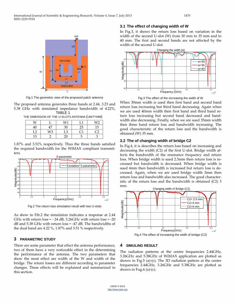
Fig.1 The geometric view of the proposed patch antenna
The proposed antenna generates three bands at 2.44, 3.23 and 5.38 GHz with simulated impedance bandwidth of 4.22%,
1.87% and 3.51% respectively. Thus the three bands satisfied the required bandwidth for the WiMAX compliant transmit-ters.
Fig.2 The return loss simulation result with two U-slots
As show in Fib.2 the simulation indicates a response at 2.44 GHz with return loss = - 24 dB, 3.26GHz with return loss = -20 dB and 5.38 GHz with return loss = -47 dB. The bandwidths of the dual band are 4.22 %, 1.87% and 3.51 % respectively.
3 PARAMETRIC STUDY There are some parameter that effect the antenna performance, two of them have a very noticeable effect in the determining the performance of the antenna. The two parameters that show the most effect are width of the W and width of the bridge. The return losses are different according to parameter changes. These effects will be explained and summarized in this section.
3.1 The effect of changing width of W In Fig.3, it shows the return loss based on variation in the width of the second U-slot (W) from 30 mm to 35 mm and to 40 mm. The first and second bands are not affected by the width of the second U-slot.
Fig.3 The effect of the increasing the width of W When 30mm width is used then first band and second band return loss increasing but third band decreasing. Again when we are used 40mm width then first band and third band re-turn loss increasing but second band decreased and band-width also decreasing. Finally, when we are sued 35mm width then three band return loss and bandwidth increasing. The good characteristic of the return loss and the bandwidth is obtained (W) 35 mm.
3.2 The of changing width of bridge C2 In Fig.4, it is describes the return loss based on increasing and decreasing the width (C2) of the first U-slot. Bridge width af-fects the bandwidth of the resonance frequency and return loss. When bridge width is sued 2.5mm then return loss is in-creased but bandwidth is decreased. When bridge width is sued 4mm then bandwidth is increased but return loss is de-creased. Again, when we are used bridge width 3mm then return loss and bandwidth also increased. The good character-istic of the return loss and the bandwidth is obtained (C2) 3 mm.
Fig.4 The effect of increasing the width of bridge (C2)
4 SIMULING RESULT The radiation patterns at the centre frequencies 2.44GHz, 3.26GHz and 5.38GHz of WiMAX application are plotted as shown in Fig.5 (a)-(c). The 3D radiation pattern at the center frequencies 2.44GHz, 3.26GHz and 5.38GHz are plotted as shown in Fug.6 (a)-(c).
TABLE 1 THE DIMENSION OF THE U-SLOTS ANTENNA (UNIT=MM)
W L W1 L1 W2 40 47 30 25 15 L2 W3 L3 C1 C2 15 2 20 5 3
2 2.5 3 3.5 4 4.5 5 5.5
x 109
-45
-40
-35
-30
-25
-20
-15
-10
-5
0S-parameter
Frequency(GHz)
Mag
nitu
de(d
B)
Excitation/ S-parameter
2 2.5 3 3.5 4 4.5 5 5.5
x 109
-50
-40
-30
-20
-10
0Changing the width (w)
Frequency (GHz)
Mag
nitu
de(d
B)
w=30w=35w=40
2 2.5 3 3.5 4 4.5 5 5.5
x 109
-50
-40
-30
-20
-10
0Changing width of Bridge (C2)
Frequency(GHz)
Mag
nitu
de(d
B)
C2= 2.5 mmC2=3 mmC2=4 mm

International Journal of Scientific & Engineering Research, Volume 4, Issue 7, July-2013 1471 ISSN 2229-5518
IJSER © 2013 http://www.ijser.org
Fig.5 (a) Radiation pattern E-plane and H-plane at 2.44GHz
Fig.5 (b) Radiation pattern E-plane and H-plane at 3.26 GHz
Fig.5 (c) Radiation pattern E-plane and H-plane at 5.38 GHz

International Journal of Scientific & Engineering Research, Volume 4, Issue 7, July-2013 1472 ISSN 2229-5518
IJSER © 2013 http://www.ijser.org
Fig.6 (a) 3D Radiation pattern at 2.44GHz
Fig.6 (b) 3D Radiation pattern at 3.26 GHz
Fig.6 (c) 3D Radiation pattern at 5.38 GHz
4 CONCLUSION This paper presented the simulation of the maicrostrip patch antenna with double U-slots. From two U- slots shape on the patch, the three bands can be generated and by adding one bridge the exact frequencies band for WiMAX can be achieved. The three frequency band 2.44GHz, 3.26GHz and 5.38GHz has been achieved as well as the bandwidth requirements for Wi-MAX standards 4.22%, 1.87% and 3.51% respectively. The re-turn loss for the triple band are -24dB, -20dB and -47dB respec-
tively. The U- slot patch antenna is designed for increasing the bandwidth and return loss but gain cannot increase. If array of the U- slot patch antenna is used then the gain can be im-proved. Therefore, the antenna will be better work in the Wi-MAX applications and wireless communications system.
REFERENCES [1] W.L. Stutzman and G.A. Thiele, Antenna Theory and Design, 2nd ed.
New York: Wiley, 1998. [2] C.A. Balanis, Antenna Theory, 2nd Ed. New York: John Wiley & sons,
Inc., 1997. [3] Hattan F. Abu Tarboush, D. Budimir, R. Nilavalan “Connected U-
slots Patch Antenna for WiMAX Applications”. International Journal of RF & Microwave CAF, 2008.
[4] H. F. AbuTarboush, H. S. Al-Raweshidy, “A Connected E-Shape and U-Shape Dual- Band Patch Antenna for Different Wireless Applica-tions”, the Second International EURASIP Workshop on RFID Tech-nology, July, 2008.
[5] M. Sanad, “Double C-patch antennas having different aperture shapes,” in Proc. IEEE Antennas and Propagation Dig., June 1995, pp.2116–2119.
[6] Murad NA. “Microstrip U-shaped dual-band antenna,” Applied Electromagnetic, 2005 APACE 2005 Asia-Pacific Conference on 2005:4 pp
[7] Hadian AM. “Wideband rectangular microstrip patch antenna with U-slot,” Antennas and Propagation, 2007 EuCAP 2007 The Second European Conference on. 2007:1-5.
[8] T. liu and L. L. Wong, “A wideband Stubby Monopole Antenna and a GPS for WiMAX Mobile Phone with E911 Function,” Microwave and Optical Technology Letter, Vol 46, 2005, pp. 485-487.