design simulation and analysis of manual block-making machine
TRANSCRIPT
Innovative Systems Design and Engineering www.iiste.org
ISSN 2222-1727 (Paper) ISSN 2222-2871 (Online)
Vol.7, No.7, 2016
19
Design simulation and analysis of manual block-making
machine Diana Starovoytova Madara, Daniel Kiptoo Arusei and Martin Njuguna Njoroge
School of Engineering, Moi University P. O .Box 3900, Eldoret, Kenya *E-mail of the corresponding author: [email protected]
Abstract This paper reports the synopsis of design simulation and analysis of manual block-making machine; it is a small fraction of a bigger research-study. Analysis of the various components that make up the final design was done in order to establish the forces, stresses and dimensions. The studies included dynamic simulation, frame analysis and stress examination. Finite Element Analysis was conducted on the components that could have failed during the normal operation of the machine; as such two analyses were done, one to investigate the effect of member components weight due to gravity and the second to investigate the effect of the return load on the frame members. All drawings, calculations, design, assembly, simulations, and Finite Element Analysis (FEA) were done by the Autodesk Inventor, 2016 Engineering Design Software. The results are: Flat lever analysis: The maximum displacement achieved was 0.0000008642mm, while the safety factor was 15ul and so the design of the flat component was acceptable if subjected to loads as exposed. However, it seems that the part is overdesigned. Compactor frame analysis: The maximum displacement was 1.605mm and considering the fixed-end would not actually be fixed in the actual machine, this displacement was found to be acceptable. The minimum safety factor achieved was 4.35ul which is acceptable and the maximum 15 ul. Complete assembly analysis: Maximum contact pressure achieved was 36.72 MPa while some components received no contact pressure from the load. The safety factor for the whole machine was 15ul. The value may lead to an assumption that the machine has been “overdesigned”, but considering that some of the sections of the machine are actually unaffected by the load, or the loading conditions is short, and allowing for that it is an equipment that intends to operate on a daily-basis, and it is made of ductile-material, operated in repeated and impact mode of loading, environmental considerations and also to account for all the unpredictable-factors, then, this safety factor for the machine is acceptable. For single components however there would be a need to reduce the “overdesigning”. The study accomplished design simulation and analysis of manual block-making machine, resulting in 3D-view of the final assembly of the machine (made of mild steel) with all standard notations. Overall, the results of this concise study are rather positive, providing a good starting point for further and much- deeper exploration on the same. The major recommendation was made vis-à-vis design factor of safety, in order to eliminate/reduce “overdesigning” and to obtain sequential solutions that exhibit asymptotic convergence to values representing the exact solution, it is recommended to conduct h-refinement of the mesh in FEA. Key words: design, simulation, assembly, analysis, block-making-machine 1. Introduction 1.1. Problem statement and the purpose of the study One of the essential preconditions for improving the standard of living of people is the provision of reasonably good housing (Smith, 2006). Rapid and uncontrolled urbanization in many developing countries, Kenya included, have resulted in a severe shortage of houses in recent years, especially in towns and sub-urban areas.
Indicators which support continuous and growing demand for housing in Kenya include: Current growth in Kenyan economy at 6.5%; High Population and urbanization growth rates; New Constituency Development Fund programs (CDF); and National Housing Corporation that is now awarding building loans with a free package of architectural drawings. This is 20% for the total building cost for a standard house (UN, 2010).
Kenya has made huge steps in promotion of ready-made concrete material for construction. Among the products in the market are roofing tiles, hollow blocks, paver blocks and the standard solid blocks. The most common producers are the commercial companies such as Lafarge group of Companies i.e. Bamburi, Kisumu Concrete Products limited among others, that have many enormous automatic machines for this purpose. On small-scale however, very few machines are available from local-producers most being those that are imported from outside the country. Not many people also actually are aware that they can produce the blocks on their own and in their own homes.
The small-scale manufacture of concrete blocks for masonry is well suited to small businesses. Production can be carried out in the open, the process is simple and equipment does not require high capital investment. Making of concrete blocks is a relatively easy task, especially if inexpensive local

Innovative Systems Design and Engineering www.iiste.org
ISSN 2222-1727 (Paper) ISSN 2222-2871 (Online)
Vol.7, No.7, 2016
20
block-making machine is made available. This study is therefore focused on design simulation and analysis of manual block-making machine.
1.2. Engineering Design and general design-considerations Design is part of a human problem-solving-activity beginning with a perception of a gap in a user experience, leading to a plan for a new artifact, and resulting in the production of that artifact. Product design is conceiving and giving form to goods and services that address needs (Burdekin, 2007).
Table 1shows the elements of product design as an example for the Ducati Monster Motorcycle, a Highly Successful Artifact Introduced in 1993.
The following factors are considered during the design process: Simplicity, Ergonomics, Aesthetics, Ease of manufacture, Availability of material and labor, Reliability, Operational and maintenance costs, Weight and size and Efficiency among others. Also the design-criteria: Usefulness; Manufacturing Producing issues and Handling and Get together are used. Usefulness A segment comprises of various parts. The utilitarian or functional part is the one that truly performs basic-task that prompts the execution of the segment. The non-functional part does not have real work in segment presence but rather it needs to do with support, spreads, examination and aesthetical worth and therefore the number of non-functional parts should be reduced to cut the cost (Juvinall & Marshek, 2012).
Table 1: The elements of product design
Source: Ulrich, 2011 Manufacturing issues Manufacturing issues mainly concerned with the assembling procedure and materials, including the following factors: Budynas-Nisbet, 2008)
Complexity-Segment's shape greatly affects the assembling technique. Different sorts of shape are logically produced by appropriate corresponding dissimilar techniques/manufacturing processes.
Material reasonableness-Material appropriateness is important when choosing the sort of materials to be utilized for a specific item, since a few materials are better than average for some procedures while some are poor because of their properties e.g. copper, zinc, lead and some aluminium composites are less demanding to work with by effect expulsion process than steel and steel amalgams are simpler to hot manufacture than aluminium compounds.
Tolerance and surface complete-The gear with high resilience will be exorbitant due to increment in preparing time and apparatuses taking care of directions which make it less demanding to be manoeuvred carefully.
Process cost-A part to be produced needs to pass diverse procedures and stages and every procedure cannot be finished without the money. Cash spent on every procedure is known as procedure-expense and the expansion of various procedure costs make the generation cost.
Waste- Some procedures are viewed as waste on account of the materials discarded as scrap while producing them and some devour truly long time to finish the procedure. It is the

Innovative Systems Design and Engineering www.iiste.org
ISSN 2222-1727 (Paper) ISSN 2222-2871 (Online)
Vol.7, No.7, 2016
21
undertaking of generation financial aspects to evaluate both circumstances and parity it and think of the best decision to be utilized.
Treatment- Surface-treatment cost depends on the kind of materials utilized. A few materials are exorbitant however due to their inherent excellent properties they do not generally require surface-treatment while some are not costly but they do require extra surface-treatment for quality enhancement.
1.3. Design factor of safety A key strategy in the PDP (Product Development Process) is to avert failure of a machine or structure by predicting and analyzing potential failure scenarios at the design stage, before the machine is built (Budynas-Nisbet, 2008). By identifying the loads, the governing failure modes and tentatively selecting the appropriate-candidate-material, the failure prediction scenarios provide a basis for choosing the optimal-combination of design parameters: geometry, material and loads.
Factor of safety (FoS), also known as (and used interchangeably with) safety factor (SF) and design factor of safety (N), is a term describing the capacity of a system beyond the expected loads or actual loads. Essentially, the factor of safety is how much stronger the system is than it usually needs to be for an intended load.
Moreover, several considerations regarding safety factors have been identified: (Iorga et.al., 2012) Safety factors are an engineering expression of the customer or product requirements from a
resistance standpoint; Safety factors can be seen as an insurance against design risks; Safety factors can embed the expertise gained using a stochastic approach or other approaches
based on experimental testing; Safety factors are generally kept confidential by companies; If disclosed, safety factors could be misused in trials, hence leading to liability in case of accident; Safety factors must nevertheless be internally documented for product traceability.
The design factor of safety (N) is often specified in a design code or standard, where a minimum factor of safety is specified. Designer’s responsibility is to determine if a code or standard applies. If not covered by code, the Designer must use good engineering judgment to determine appropriate value. The simplest interpretation of the Factor of Safety is, FoS = Strength of Component / Load on component. Safety factor selection must be undertaken with care to avoid the negative consequences associated with the selected values (safety factor too small =high probability of failure; safety factor too large =cost, weight or size too high); (Clausen et. al., 2006). Table 2 shows the factor of safety guidelines. Factors which affect the factor of safety are: Material strength (brittle materials – use ultimate strength; ductile materials – use yield strength). Manner or loading (Static – applied slowly; remains applied or is infrequently removed; Repeated – fatigue failure may occur at stresses lower than static load failure; and Impact – high initial stresses develop). Possible misuse – designer must consider any reasonable foreseeable use & misuse of a product. Environment – temperature, weather, radiation, chemical, etc.
Table 2: Design factor of safety (N) guidelines
Source: (www. Factor_of_safety.pdf) Factor of safety is also depends on the intended end-use of the product. For example, Equipment Factor of Safety( FOS) for: Aircraft components 1.5 - 2.5; Boilers 3.5 – 6; Bolts 8.5; Cast-iron wheels 20; Engine components 6 – 8; Heavy duty shafting 10 – 12; Lifting equipment – hooks 8 – 9; Pressure vessels 3.5 – 6; Turbine components – static 6 – 8; Turbine components – rotating 2 – 3; Spring, large heavy-duty 4.5; Structural steelwork in buildings 4 – 6; Structural steelwork in bridges 5 – 7; and Wire ropes 8 – 9 (Iorga et.al., 2012; EngineeringToolbox, 2016).
Throughout this design study, safety factors were given prominence to avoid endangering the life of the user. This is due to the fact that the machine maybe used by unskilled and uneducated-personnel in the “jua kali” (informal) sector where the machine is meant to benefit most.
Innovative Systems Design and Engineering www.iiste.org
ISSN 2222-1727 (Paper) ISSN 2222-2871 (Online)
Vol.7, No.7, 2016
22
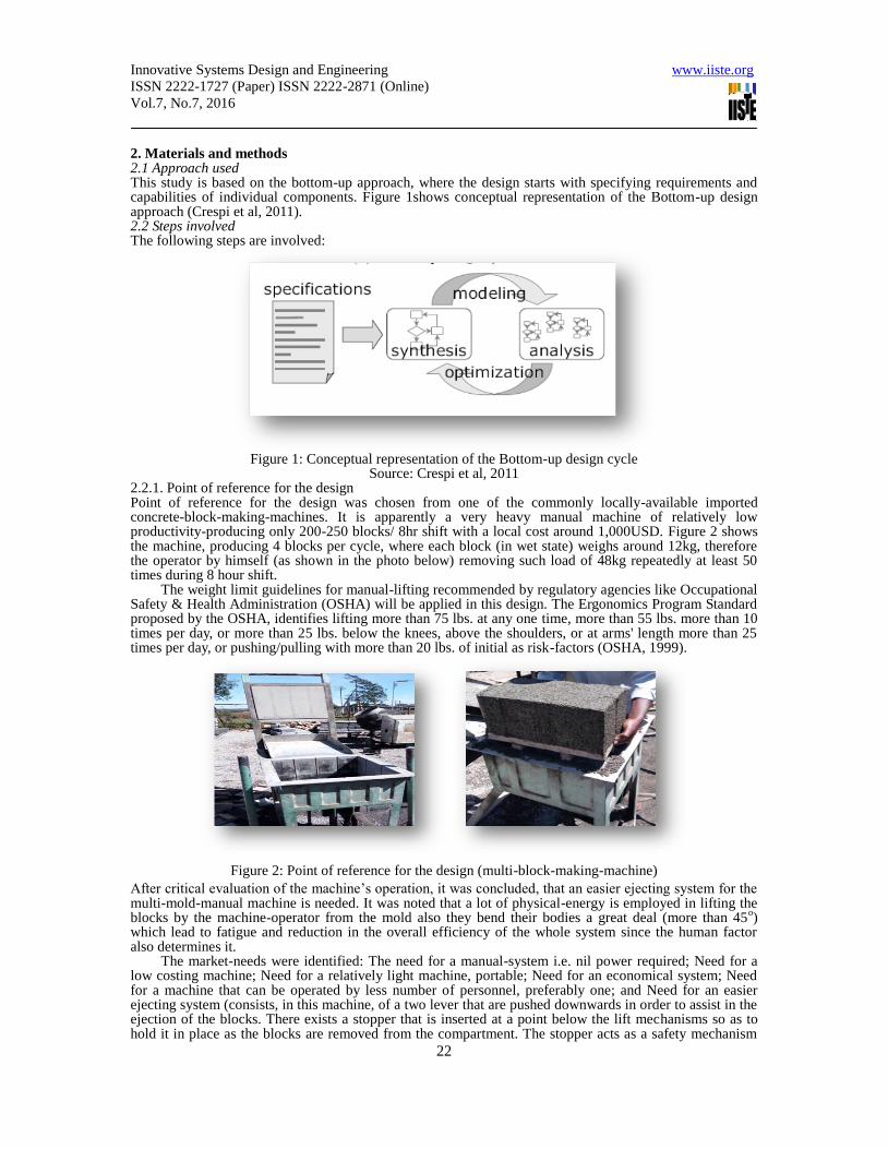
2. Materials and methods 2.1 Approach used This study is based on the bottom-up approach, where the design starts with specifying requirements and capabilities of individual components. Figure 1shows conceptual representation of the Bottom-up design approach (Crespi et al, 2011). 2.2 Steps involved The following steps are involved:
Figure 1: Conceptual representation of the Bottom-up design cycle
Source: Crespi et al, 2011 2.2.1. Point of reference for the design Point of reference for the design was chosen from one of the commonly locally-available imported concrete-block-making-machines. It is apparently a very heavy manual machine of relatively low productivity-producing only 200-250 blocks/ 8hr shift with a local cost around 1,000USD. Figure 2 shows the machine, producing 4 blocks per cycle, where each block (in wet state) weighs around 12kg, therefore the operator by himself (as shown in the photo below) removing such load of 48kg repeatedly at least 50 times during 8 hour shift.
The weight limit guidelines for manual-lifting recommended by regulatory agencies like Occupational Safety & Health Administration (OSHA) will be applied in this design. The Ergonomics Program Standard proposed by the OSHA, identifies lifting more than 75 lbs. at any one time, more than 55 lbs. more than 10 times per day, or more than 25 lbs. below the knees, above the shoulders, or at arms' length more than 25 times per day, or pushing/pulling with more than 20 lbs. of initial as risk-factors (OSHA, 1999).
Figure 2: Point of reference for the design (multi-block-making-machine)
After critical evaluation of the machine’s operation, it was concluded, that an easier ejecting system for the multi-mold-manual machine is needed. It was noted that a lot of physical-energy is employed in lifting the blocks by the machine-operator from the mold also they bend their bodies a great deal (more than 45
o)
which lead to fatigue and reduction in the overall efficiency of the whole system since the human factor also determines it.
The market-needs were identified: The need for a manual-system i.e. nil power required; Need for a low costing machine; Need for a relatively light machine, portable; Need for an economical system; Need for a machine that can be operated by less number of personnel, preferably one; and Need for an easier ejecting system (consists, in this machine, of a two lever that are pushed downwards in order to assist in the ejection of the blocks. There exists a stopper that is inserted at a point below the lift mechanisms so as to hold it in place as the blocks are removed from the compartment. The stopper acts as a safety mechanism

Innovative Systems Design and Engineering www.iiste.org
ISSN 2222-1727 (Paper) ISSN 2222-2871 (Online)
Vol.7, No.7, 2016
23
since the compartment will drop back to its initial position due to the weight of the blocks). 2. 2.2 Preliminary Calculations Bulk density, Weight in mix and Volume in mix were calculated for all the materials of a concrete-block (the approximate mixing ratio of materials: Aggregate (13.4 parts), Sand (4.8 parts), Cement (2.5 parts) and Water (1 part)) the volume of a block, the block mass, the total volume of six blocks, and finally the volume of the mold-compartment were determined according to Hornbostel & Caleb (1991) and fundamental Civil engineering design principles. Regarding ejection-mechanism; in solving the forces on each link and joint, the forces are resolved along the x and y-axis and moments at pin joint A and B respectively and the resulting forces on the pin joint are determined. For the design of the base plate, critical buckling force, deflection, angular displacement and torque were resolved according to Budynas-Nisbet (2008) and fundamental engineering design principles.
2. 2. 3. Design specifications used The design specifications are based on the customer needs as point of reference and technical standards as per the British Aggregate concrete masonry units standards BS EN 771-3 (5): Standard block Specification. Concrete blocks may be characterized using the following specifications:
a) Dimensions (Block dimensions will be specified in the order length x width x height, for example (152x229x406mm). The tolerances in the sizes will be according to the industrial standards (BS EN 771-3 standards) shown in Table 3
Table 3: Tolerances permitted by BS EN 771-3 (5)
Tolerance design Category
D1 mm
D2 mm
Length +3 +1 -5 -3
Width +3 +1 -5 -3
Height +3 +2 -5 -2
b) Block Strengths (Blocks are available in compressive strengths from 2.9N/mm² to 40N/mm² (Solid) and 2.9N/mm² to 22.5N/mm² (cellular and hollow). Common strengths are 3.6N/mm² and 7.3N/mm²).
c) Density (Aggregate concrete blocks are available in the net dry density range of 650 – 2400kg/m³ with a tolerance of ± 10%).
d) Configuration (According to BS EN 771-3 blocks can be categorized into one of the following groups based on percentage of voids: Group 1 < 25% formed voids; Group 2 > 25% < 60% formed vertical voids; Group 3 > 25% < 70% formed vertical voids; Group 4 > 25% < 50% formed horizontal voids. Generally hollow blocks fall under group 2 and group 3 while the solid blocks are in group 1).
This design will be on concrete-block-making-machine for solid-blocks. 2. 2.3. Machine to be designed The major operations performed by a concrete-block-making-machine include shaping and compaction of concrete to form concrete-blocks. The machine will involve production of six blocks at one cycle. Several alternative- designs as free hand-sketches are created by the design-team; and the best design selected via the standard engineering design weighted-score matrix. Only the best alternative-design is considered as the subject of the Final design simulation and analysis. 2. 2.4. Final design simulation and analysis The final design process started with hand-sketches of individual functional-components of the machine, with specifying requirements and capabilities of each, followed by drawing of the same via the software.
Through-out the design process, analysis of the various components that make up the final design was done. The various studies included dynamic simulation, frame analysis and stress analysis. Finite Element Analysis was done on components that could have failed during the normal operation of the machine due to potential stresses and deflections, so as to achieve the right component dimensions to ensure reduced failure rates. All drawings, calculations, design, assembly, simulations, and Finite Element Analysis (FEA) were done by the Autodesk Inventor, 2016 Engineering Design Software (professional edition). 2. 2.5. Final assembly The final 3D assembly with proper dimensions of the machine was generated based on the conducted simulations, calculations and analysis. 2.3. Tools used in the study Two major tools selected are: Autodesk Inventor, 2016 Engineering Design Software (professional edition) and Finite Element Analysis (FEA).

Innovative Systems Design and Engineering www.iiste.org
ISSN 2222-1727 (Paper) ISSN 2222-2871 (Online)
Vol.7, No.7, 2016
24
Autodesk Inventor, 2016 (professional edition) is a 3D mechanical engineering, design, visualization, and simulation software. It was chosen as a main tool for the design and analysis due to its unique capabilities, such as: it is a parametric and feature-based solid-modeling-tool; It allows to convert the basic 2D sketch into a solid model; it creates digital prototyping as opposed to physical prototyping (which is costly and time-consuming) by integrating 2D AutoCAD drawing and 3D data into a single digital model; it has a simulation environment that allows motion simulation, static and modal Finite Element Analysis (FEA) of parts, assemblies and load-bearing frames. In addition new safety factor calculation warning displays in Stress Analysis. Basically a solid model of the element is to be created in the first step, the rest of the process like creating a standard drawing in either first or third angle projection method with different views ( like orthographic, isometric, auxiliary, sectional, and perspective) is completely automated. The process of adding dimensions (with all standard notations) to the drawing is also automated.
The finite element method (FEM), or finite element analysis (FEA), is a computational technique used to obtain approximate solutions of boundary/field value problems in engineering. It was chosen as one of the tools for this study, because it enables to identify the optimal design with high degree of confidence. The values of the field variable computed at the nodes are used to approximate the values at non-nodal points (that is, in the element interior) by interpolation of the nodal values. The primary characteristics of a finite element are embodied in the element stiffness matrix. For a structural finite element, the stiffness matrix contains the geometric and material behavior information that indicates the resistance of the element to deformation when subjected to loading. Such deformation may include axial, bending, shear, and torsional effects. Another fundamental concept of FEM is Discretizations (Model body by dividing it into an equivalent system of many smaller bodies or units (finite elements) interconnected at points common to two or more elements (nodes or nodal points) and/or boundary lines and/or surfaces (Barkanov, 2001).
In FEA, solution accuracy is judged in terms of convergence as the element “mesh” is refined. There are two major methods of mesh refinement. In the first, known as h-refinement, mesh refinement refers to the process of increasing the number of elements used to model a given domain, consequently, reducing individual element size. In the second method, p-refinement, element size is unchanged but the order of the polynomials used as interpolation functions is increased. The objective of mesh refinement in either method is to obtain sequential solutions that exhibit asymptotic convergence to values representing the exact solution. The FEA procedure followed in this study can be divided into three distinct steps:
(1) Build the model (In this step, the job-name and analysis title should be specified and then by the use of pre-processor the element types, element real constants, material properties, and the model geometry should be defined). With “solid modeling”, after the geometric boundaries of the model described, then the program should be instructed to automatically mesh the geometry with nodes and elements. In this study Triangular mesh is considered for the analysis.
(2) Apply loads and obtain the solution (In this step, use SOLUTION menu to define the analysis type and analysis options, apply loads, specify load step options, and initiate the finite element solution). After SOLVE command, the program takes model and loading information from the database and calculates the results.
(3) Review the results (Once the solution has been calculated, the postprocessors can be used to review the results. Two postprocessors are available: the general postprocessor and the time-history postprocessor. The general postprocessor, is used to review results at one sub-step (time step) over the entire model. Contour displays, deformed shapes, and tabular listings can be obtained to review and interpret the results of the analysis. Many other capabilities are available, including error estimation, load case combinations, calculations among results data, and path operations. The time-history postprocessor, is used to review results at specific points in the model over all time steps. Graph plots of results data versus time (or frequency) and tabular listings can be obtained. Other capabilities include arithmetic calculations, and complex algebra. 3. Results 3.1. Preliminary Calculations Among the major calculations that the project was involved in was the determination of the block sizes that will economically be produced by the system. Civil & Structural design concepts and engineering knowledge was applied with factors such as the correct proportions of the concrete-block- mixture determined. A concrete-block density of 24KN/m was considered in reference to British Standard BS 5628:2005 – Code of Practice for the use of Masonry and the following results attained as shown in Table 4. Note that BS 5628-1:2005 Section 2 clause 7 and BS 5628-2:2005 Section 6 clause 6.2 requires that aggregate concrete masonry units comply with the requirements of BS EN 771-3.

Innovative Systems Design and Engineering www.iiste.org
ISSN 2222-1727 (Paper) ISSN 2222-2871 (Online)
Vol.7, No.7, 2016
25
Table 4: Obtained results
Materials of a
concrete- block
Bulk density (g/cm
3)
Weight in mix (kg/m
3)
Volume in mix (m
3)
Sand 1.44 0.3456 0.24
Aggregate 1.56 0.9672 0.62 Cement 2.5 0.18 0.07 Water 1 0.072 0.073
∑ 1.5648 1.003
W/C (Water to Cement ration) is 0.4; The final alternative design will involve production of six blocks in one cycle/press. The blocks sizes are: 5 blocks of 16 x 4 x 8 (inches) and 1 block of 20x 4x 8 (inches). Figure 3 shows the arrangement of the blocks in the mould-compartment.
Figure 3: Arrangement of the blocks in the mold-compartment Volume of blocks: 16 inch length blocks V= L x W x H= (16×2.54)×(4×2.54)×(8×2.54)=8390.178cm
3,
therefore for 5 blocks = 5 ×8390.178= 41950.8838cm3
; Analogous, 20 inch length block = (20×2.54)×(4×2.54)×(8×2.54) =10487.72096cm
3 ; The total volume of six blocks will be = 41950.8838 +
10487.72096= 52,438.6048 cm3 . Therefore, the min volume of the compartment will be equal to, assuming
that the amount of voids is 5% by Volume: Compartment (Min. volume) 52,438.6048×1.05 =55,060. 53504 cm
3
* Note: This is not the final volume of the compartment as other assembly-components are in direct contact and interfere with its overall size, i.e. the base plate on which the material is filled, the 5 divider plates, used to divide the different blocks (3mm thick) and the compactor plate which has to get inside the compartment fully for complete compaction to occur, all are involved in the determination of the final internal volume of the compartment. Block mass = Weight in Mix × Block Volume; 16’ Block mass=1.5648 × 8.390= 13.12867 Kg and 20’ Block Mass= 1.5648 × 10.4877= 16.41115Kg; therefore the total Weight of all 6 blocks in a mold is around 82kg. 3.2. Best design- alternative From the design criteria, design considerations and the point of reference for the design, four free-hand-sketches of the proposed machine were done, and the best design was selected via the standard engineering design weighted-score matrix. The fundamental difference between the point of the reference for the design and the best-alternative design is in the ejection mechanism. The best-alternative design essentially involves a simple lever-mechanism (ejection mechanism) to bring down the mold compartment to a base level that allows for the lifting of the already compacted blocks easily done by one operator (now no manual lifting of the blocks from the compactor is involved).
Figure 4 shows the Lever mechanism. The lever is attached to the mold compartment by use of two pin joints that are welded to two welded bars to the compartment on one set of two opposite faces of the mold compartment. By lifting/raising the lever by the arm handle, the direction of the mold compartment is in the opposite direction i.e. downwards and the vice versa is done to start the material filling process again

Innovative Systems Design and Engineering www.iiste.org
ISSN 2222-1727 (Paper) ISSN 2222-2871 (Online)
Vol.7, No.7, 2016
26
after all the six blocks have been successfully taken to the drying section. Thus with this design, the personnel involved with the production of the blocks is not faced with the huge load of approximately 82kg of blocks to either raise or lower them, their work is made easier firstly as the only the only force required is that of lowering the compartment which is order of 20N, much lighter than the weight of all the blocks and secondly, the lever-mechanism makes the effort to lower/raise the compartment even lesser. Two runner/guiding shafts made of stainless steel will allow the mold to make this up-down movement with ease.
Figure 4: Lever mechanism
3. 3. Selection of materials The materials selection was done according to Ashby (2005). Mild steel was chosen as major material due to its properties, such as: It is one of the most common of all metals and one of the least expensive steels used, It is weld-able, very durable; it is relatively hard and is easily annealed; Having less than 2% Carbon it will magnetize; Its inherent properties allow electrical current to flow easily through it without upsetting its structural integrity. This is in contrast to other high-carbon-steels like stainless-steel which require specialized welding techniques; This mild variant of harder steel is thus far less brittle and can therefore give and flex in its application where a harder more brittle material would simply crack and break.
4. Final design simulation and analysis
Only the best-alternative design was the subject of the Final design simulation and analysis. The results of the various tests are as follows:
4. 1. Flat lever analysis 4.1.1 FEA test The FEA test was carried out on the flat lever members, which are made of mild steel material with its specifications shown in Table 5.
Table 5: Mild steel specifications
Material Steel, Mild Density 7.85 g/cm^3
Mass 0.909181 kg Area 45445.9 mm^2
Volume 115819 mm^3
Center of Gravity x=0.0000000000284268 mm
y=3mm z=0 mm
The simulation of the flat lever bar with 10N/mm load applied on the pin joints is shown in Figure 5, where Constraint 1 shown as upwards pointing arrow and Constraint 2 shown as downwards pointing arrow; while Table 6 shows the summary of FEA on Reaction Force and Moment on Constraints for flat lever bar.

Innovative Systems Design and Engineering www.iiste.org
ISSN 2222-1727 (Paper) ISSN 2222-2871 (Online)
Vol.7, No.7, 2016
27
Fugure 5: Lever analysis 4.1. 2 Displacement and Safety factor analysis The maximum displacement achieved when the flat lever component was subjected to the loads specified was 0.0000008642mm, which was hardly noticeable and hence the part was decided to be acceptable to work in those conditions as specified.
Table 6: Summary of FEA on Reaction Force and Moment on Constraints for flat lever bar
Constraint Name
Reaction Force Reaction Moment
Magnitude Component (X,Y,Z)
Magnitude Component (X,Y,Z)
Pin
Constraint:1
9.99964 N
0.251528 N 0 N m
0 N m
0 N 0 N m
-9.99647 N 0 N m
Pin
Constraint:2
9.9999 N
-0.414586 N 0 N m
0 N m
0 N 0 N m
9.9913 N 0 N m
The safety factor achieved for the component was 15ul (In Autodesk Inventor, 2016 "ul" means "uniteless", and this is being shown because the safety factor has no units) and so the design of the flat component was acceptable if subjected to loads as shown. However, it seems that the part is “overdesigned”. Figure 6 and Figure 7 show Displacement and Safety factor simulations respectively.
Fig 6: Displacement analysis Fig 7: Safety factor analysis 4.2. Compactor frame analysis The compactor consists of a load at one end to act as a return-mechanism so that there is ease in compaction the concrete mixture. Two analyses were done, one to investigate the effect of member components weight due to gravity and the second to investigate the effect of the return load on the frame members. The resulting distributions are as shown below:
i) Effect of gravity The analysis assumed fixed ends of the end compactor frame members subjected to their own weight and the weight of the compacting plate. Essentially the ends of the compactor are not fixed and hence the analysis was to show how strong the frame members are considering the above conditions.

Innovative Systems Design and Engineering www.iiste.org
ISSN 2222-1727 (Paper) ISSN 2222-2871 (Online)
Vol.7, No.7, 2016
28
The maximum displacement the frame member achieved under the tests was 1.605mm as shown in Figure 8. Considering the fixed end would not actually be fixed in real the actual machine, this displacement was found to be acceptable.
Figure 8: Displacement analysis Figure 9: Effect due to the return load ii) Effect due to the return load
This analysis involved the use of a 10N load on the other end of the frame so as to counter the effect of the load at the pin joints for the effects to be investigated. The system consists of 50,049 nodes and 24,271 elements. The minimum safety factor achieved was 4.35ul which is acceptable and the maximum 15 ul, which shown in Figure 9, while Table 7 shows the summary of FEA on Reaction Force and Moment on Constraints for compactor frame
4.3 Complete assembly analysis This analysis involved the full mass of the concrete mixture per cycle to simulate how the system will respond to the loading. The weight of the whole concrete material was calculated as 82 kg and an allowance of +2kg was given and so the machine was subjected to a load of 840N.
The assembly system consists of 330,405 nodes and 180,791 elements. Maximum contact pressure achieved was 36.72 MPa while some components received no contact pressure from the load.
The safety factor for the whole machine, considering the effect of the load at the base plate, achieved was 15ul. The results are shown in Figure 10. If an assemblage of components is subjected to a single load, the assembly's safety factor is the smallest of the component safety factors - 'a chain is only as strong as its weakest link', therefore only min value is shows by the program. This value of 15ul may lead to an
Table7: Summary of FEA on Reaction Force and Moment on Constraints for compactor frame.
Constraint Name
Reaction Force
Reaction Moment
Magnitude Components (Fx, Fy, Fz)
Magnitude Components (Mx, My, Mz)
Fixed
Constraint:2
68.298 N
-0.586 N 50614.537
N mm
50614.435 N mm
68.296 N 99.869 N mm
0.020 N -16.856 N mm
Fixed
Constraint:1
68.182 N
0.586 N 50541.705
N mm
50541.624 N mm
68.180 N -88.591 N mm
-0.020 N 17.837 N mm
assumption that the machine has been “overdesigned”, however considering that some of the sections of the machine are actually unaffected by the load, or the loading conditions are short, and taking into account that it is an equipment that supposed to be operational on a daily-basis, and that it is made of ductile material, and the mode of loading is repeated and impact, and also to account for environmental considerations and all the unpredictable factors, such as possible misuse, for example, then this safety factor for the machine assembly is acceptable. For single components however there would be a need to reduce the “overdesigning”.

Innovative Systems Design and Engineering www.iiste.org
ISSN 2222-1727 (Paper) ISSN 2222-2871 (Online)
Vol.7, No.7, 2016
29
Figure 10: Safety factor of the assembly
4. 5. Final assembly Figure 11 shows the 3D-view of the final assembly of the machine, while Figure 12 shows the calculated dimensions for the same. The machine consists of 37 items, and the major material of the parts is mild steel.
Figure11: The 3D view of the machine with the overall dimensions.
Figure 12: Shape and calculated dimensions for mold, compactor, lever and divider-plate. The Video (avi format) of the simulation of the operation of the concrete-block-making machine is available on request.
Innovative Systems Design and Engineering www.iiste.org
ISSN 2222-1727 (Paper) ISSN 2222-2871 (Online)
Vol.7, No.7, 2016
30
5. Conclusion and Recommendations The study accomplished design simulation and analysis of manual block-making machine, resulting in 3D-view of the final assembly of the machine with all standard notations. Vis-à-vis design factor of safety, to eliminate/reduce “overdesigning” and to obtain sequential solutions that exhibit asymptotic convergence to values representing the exact solution, it is recommended to conduct h-refinement of the mesh in FEA.
Regarding mild steel, chosen as the major raw material; it is recommended because of its poor resistance to corrosion that it must be protected by painting or otherwise sealed to prevent it from rusting. At worst a coat of oil or grease will help seal it from exposure and prevent rusting.
Overall, the results of this concise study are rather positive, providing a good starting point for further and much- deeper exploration on the same. Eventually, if this simple equipment is successful, the Government, through its local authorities, is targeted in its purchase, which may contribute, in its small way, in so-needed numerous construction development and housing projects all around Kenya.
Lastly, the authors would like to emphasize that there is absolutely nothing that can ever be perfect that is made by man, especially when it is at its initial stages and hence the authors would like to welcome constructive expert-criticism from the readers (if any). 6. Acknowledgements The authors wish to acknowledge Peter Waichigo for his cooperative and valuable- assistance in conducting design-experiments. References Ashby, M.F. (2005): Materials Selection in Mechanical Design, 3
rd Edition, ELSEVIER
Butterworth-Heinemann Publications, U.K, ISBN 0 7506 6168 2. Autodesk Inventor, 2016 (professional edition) Barkanov, E. (2001). Introduction To The Finite Element Method, Institute of Materials and Structures, Faculty of Civil Engineering, Riga Technical University. BS EN 771-3: Aggregate concrete masonry units Concrete block Association, 2006, February. BS 5628:2005 – Code of practice for the use of masonry. Mortar-less masonry Design Manual Part 1 (BS 628:2005), Section 1 Budynas-Nisbet, F. (2008) Shigley’s Mechanical Engineering Design (8th edition), McGraw-Hill’s, 1054 pp. {ISBN 0-390-76487-6} Burdekin F. M., (2007) General principles of the use of safety factors in design and assessment, Engineering Failure Analysis, pp. 420-430. Clausen J., Hansson S., Nilsson F. (2006), Generalizing the safety factor approach, Reliability Engineering and System Safety, pp. 964-973. Crespi, V., Galstyan, A., & Lerman, K.(2011) Top–Down vs Bottom–up Methodologies in Multi–Agent System Design, Department of Computer Science, California State University, Los Angeles and USC Information Sciences Institute Autonomous Robots. EngineeringToolbox (2016) [Online] Available: http://www.engineeringtoolbox.com/factors-safety-fos-d_1624.html, (June 10, 2016) Factor of Safety, N, [Online] Available: http://engr.bd.psu.edu/rxm61/213/problems/factor_of_safety.pdf Hornbostel & Caleb (1991) Construction Materials, 2nd Edition. John Wiley and Sons, Inc. (May 26, 2016) Iorga,C., Desrochers,A. & Smeesters, C. (2012) Engineering design from a safety perspective. CEEA12; Paper 005 Winnipeg, MB; Proc. 2012 Canadian Engineering Education Association (CEEA12) Conf. June 17-20, 2012 – 1/6 Juvinall R, C. & Marshek K.M. (2012): Fundamentals of Machine Component Design. 5
th edition, John
Wiley & Sons, Inc., USA, ISBN-13 9781118012895. OSHA Technical manual (1999). U.S. Department of Labor, O. S. Smith, D.A. (2006), Housing the World’s Poor, The four essential roles of government, Harvard International Review Ulrich, K.T. (2011), Design Is Everything? J prod innov manag 2011; 28:394–398 UN (2010), The State of African Cities 2010: Governance, Inequality and Urban Land Markets. Nairobi: UN-Habitat.