design rules for bridge bearings and expansion joints
TRANSCRIPT

AP-R405-12
AUSTROADS RESEARCH REPORT
Design Rules for Bridge Bearings and Expansion Joints
Design Rules for Bridge Bearings and Expansion Joints

Design Rules for Bridge Bearings and Expansion Joints
Published June 2012
© Austroads Ltd 2012
This work is copyright. Apart from any use as permitted under the Copyright Act 1968, no part may be reproduced by any process without the prior written permission of Austroads.
Design Rules for Bridge Bearings and Expansion Joints
ISBN 978-1-921991-26-4
Austroads Project No. TS1600
Austroads Publication No. AP–R405-12
Project Manager Dr Ross Pritchard, DTMR Qld
Prepared by
Dr Hanson Ngo, Ian Steele and Dr Neal Lake ARRB Group
Published by Austroads Ltd Level 9, Robell House 287 Elizabeth Street
Sydney NSW 2000 Australia Phone: +61 2 9264 7088
Fax: +61 2 9264 1657 Email: [email protected]
www.austroads.com.au
Austroads believes this publication to be correct at the time of printing and does not accept responsibility for any consequences arising from the use of information herein. Readers should
rely on their own skill and judgement to apply information to particular issues.

Design Rules for Bridge Bearings and Expansion Joints
Sydney 2012

About Austroads Austroads’ purpose is to:
promote improved Australian and New Zealand transport outcomes
provide expert technical input to national policy development on road and road transport issues
promote improved practice and capability by road agencies.
promote consistency in road and road agency operations.
Austroads membership comprises the six state and two territory road transport and traffic authorities, the Commonwealth Department of Infrastructure and Transport, the Australian Local Government Association, and NZ Transport Agency. Austroads is governed by a Board consisting of the chief executive officer (or an alternative senior executive officer) of each of its eleven member organisations:
Roads and Maritime Services New South Wales
Roads Corporation Victoria
Department of Transport and Main Roads Queensland
Main Roads Western Australia
Department of Planning, Transport and Infrastructure South Australia
Department of Infrastructure, Energy and Resources Tasmania
Department of Lands and Planning Northern Territory
Department of Territory and Municipal Services Australian Capital Territory
Commonwealth Department of Infrastructure and Transport
Australian Local Government Association
New Zealand Transport Agency.
The success of Austroads is derived from the collaboration of member organisations and others in the road industry. It aims to be the Australasian leader in providing high quality information, advice and fostering research in the road transport sector.

Design Rules for Bridge Bearings and Expansion Joints
A u s t r o a d s 2 0 1 2
— i —
CONTENTS
INTRODUCTION ............................................................................................................................ 1
1.1 Background ........................................................................................................................... 1 1.2 Aims ...................................................................................................................................... 1 1.3 Scope .................................................................................................................................... 1 1.4 Outline ................................................................................................................................... 1
PART I – BRIDGE BEARINGS ....................................................................................................... 2
1 INTRODUCTION ................................................................................................................... 3
2 LITERATURE REVIEW ON BRIDGE BEARINGS................................................................. 4
2.1 General .................................................................................................................................. 4 2.1.1 Historical Development ............................................................................................ 4 2.1.2 Functions of Bridge Bearings ................................................................................... 5 2.1.3 General Design Considerations ................................................................................ 5
2.2 Common Types of Bridge Bearings ....................................................................................... 6 2.2.1 Elastomeric Bearings ............................................................................................... 6 2.2.2 Pot Bearings ............................................................................................................ 9 2.2.3 Mechanical Bearings .............................................................................................. 13 2.2.4 Disc and Spherical Bearings .................................................................................. 16 2.2.5 General Causes of Bearing Failure ........................................................................ 18
2.3 Design Codes/Specifications ............................................................................................... 18 2.3.1 AASHTO LRFD Bridge Design Specification .......................................................... 18 2.3.2 European EN 1337 ................................................................................................. 23 2.3.3 Comparison of AS 5100 with AASHTO LRFD and EN 1337 ................................... 27
3 AUSTRALIAN MANUFACTURERS OF BRIDGE BEARINGS ............................................ 28
3.1 Granor Rubber and Engineering Pty. Ltd ............................................................................. 28 3.1.1 Types of Bearings Manufactured ............................................................................ 28 3.1.2 Manufacturer Recommendations ........................................................................... 30
3.2 Ludowici ............................................................................................................................... 32 3.2.1 Types of Bearings Manufactured ............................................................................ 32 3.2.2 Manufacturer Recommendations ........................................................................... 33
3.3 Trelleborg ............................................................................................................................ 34 3.3.1 Types of Bearings Manufactured ............................................................................ 34 3.3.2 Manufacturer Recommendations ........................................................................... 36
4 STATE ROAD AUTHORITY EXPERIENCES WITH BRIDGE BEARINGS ......................... 37
4.1 Popular Types of Bridge Bearings Used Nationwide ............................................................ 37 4.1.1 Elastomeric Bearings ............................................................................................. 37 4.1.2 Pot Bearings .......................................................................................................... 39 4.1.3 Mechanical Bearings .............................................................................................. 40 4.1.4 Mortar Pads ........................................................................................................... 42
4.2 Roads and Maritime Services, New South Wales (RMS) ..................................................... 43 4.2.1 Specifications ......................................................................................................... 43 4.2.2 Design and Construction ........................................................................................ 44 4.2.3 Testing ................................................................................................................... 45 4.2.4 Failures .................................................................................................................. 45 4.2.5 Repair and Maintenance ........................................................................................ 48

Design Rules for Bridge Bearings and Expansion Joints
A u s t r o a d s 2 0 1 2
— ii —
4.3 Roads Corporation, Victoria (VicRoads) ............................................................................... 48 4.3.1 Specifications ......................................................................................................... 49 4.3.2 Design and Construction ........................................................................................ 49 4.3.3 Testing ................................................................................................................... 50 4.3.4 Failures .................................................................................................................. 50 4.3.5 Repair and Maintenance ........................................................................................ 51
4.4 Department of Transport and Main Roads, Queensland (TMR) ........................................... 51 4.4.1 Specifications ......................................................................................................... 51 4.4.2 Design and Construction ........................................................................................ 52 4.4.3 Testing ................................................................................................................... 52 4.4.4 Failures .................................................................................................................. 52 4.4.5 Repair and Maintenance ........................................................................................ 53
4.5 Main Roads Western Australia (MRWA) .............................................................................. 53 4.5.1 Specifications ......................................................................................................... 53 4.5.2 Design and Construction ........................................................................................ 54 4.5.3 Testing ................................................................................................................... 54 4.5.4 Failures .................................................................................................................. 54 4.5.5 Repair and Maintenance ........................................................................................ 55
4.6 Department of Planning, Transport and Infrastructure, South Australia (DPTI) .................... 55 4.6.1 Specifications ......................................................................................................... 55 4.6.2 Design and Construction ........................................................................................ 55 4.6.3 Testing ................................................................................................................... 56 4.6.4 Failures .................................................................................................................. 56 4.6.5 Repair and Maintenance ........................................................................................ 58
4.7 Department of Infrastructure, Energy and Resources, Tasmania (DIER) ............................. 58 4.7.1 Specifications ......................................................................................................... 58 4.7.2 Design and Construction ........................................................................................ 59 4.7.3 Testing ................................................................................................................... 59 4.7.4 Failures .................................................................................................................. 60 4.7.5 Repair and Maintenance ........................................................................................ 60
4.8 Department of Lands and Planning, (formerly Department of Planning and Infrastructure) Northern Territory (DPI) ................................................................................ 60 4.8.1 Specifications ......................................................................................................... 60 4.8.2 Design and Construction ........................................................................................ 60 4.8.3 Testing ................................................................................................................... 60 4.8.4 Failures .................................................................................................................. 60 4.8.5 Repair and Maintenance ........................................................................................ 60
4.9 ACT Department of Territory and Municipal Services (ACT TAMS) ..................................... 61 4.9.1 Specifications ......................................................................................................... 61 4.9.2 Design and Construction ........................................................................................ 61 4.9.3 Testing ................................................................................................................... 61 4.9.4 Failures .................................................................................................................. 61
4.10 New Zealand Transport Agency (NZTA) .............................................................................. 63 4.10.1 Specifications ......................................................................................................... 63 4.10.2 Design and Construction ........................................................................................ 63 4.10.3 Testing ................................................................................................................... 64 4.10.4 Failures .................................................................................................................. 64 4.10.5 Repair and Maintenance ........................................................................................ 64
4.11 Summary on SRA’s Practice ................................................................................................ 64 4.11.1 Modes of Failures ................................................................................................... 64 4.11.2 State Specifications and Technical Standards ........................................................ 65 4.11.3 Recommendations ................................................................................................. 65

Design Rules for Bridge Bearings and Expansion Joints
A u s t r o a d s 2 0 1 2
— iii —
5 INVESTIGATION INTO COMMON FAILURES OF BRIDGE BEARINGS ........................... 66
5.1 Proposed Investigation ........................................................................................................ 66 5.2 Elastomeric Bearings ........................................................................................................... 66
5.2.1 Identified Problems ................................................................................................ 66 5.2.2 Root Causes .......................................................................................................... 66 5.2.3 Suggested Maintenance to Rectify the Problems ................................................... 67 5.2.4 Possible Upgrade and Modification ........................................................................ 67 5.2.5 Proposed Changes to AS 5100 for Future Use....................................................... 67
5.3 Pot Bearings ........................................................................................................................ 68 5.3.1 Identified Problems ................................................................................................ 68 5.3.2 Root Causes .......................................................................................................... 68 5.3.3 Suggested Maintenance to Rectify the Problems ................................................... 68 5.3.4 Possible Upgrade and Modification ........................................................................ 69 5.3.5 Proposed Changes to AS 5100 for Future Use....................................................... 69
5.4 Proposed Changes for Other Bearing Types ....................................................................... 71 5.4.1 Plain Pads and Strips ............................................................................................. 71 5.4.2 Mechanical Bearings .............................................................................................. 72
6 PROPOSED BEARING SPECIFICATION DEVELOPMENT ............................................... 73
6.1 Background ......................................................................................................................... 73 6.2 Generic Specification for Spherical and Disc Bearings ......................................................... 73
6.2.1 General Requirements ........................................................................................... 73 6.2.2 Spherical Bearings ................................................................................................. 75 6.2.3 Disc Bearings ......................................................................................................... 75
7 CONCLUSION AND FUTURE DIRECTIONS ...................................................................... 77
PART II – EXPANSION JOINTS .................................................................................................. 78
1 INTRODUCTION ................................................................................................................. 79
2 LITERATURE REVIEW ON EXPANSION JOINTS ............................................................. 80
2.1 General ................................................................................................................................ 80 2.1.1 Historical Development .......................................................................................... 80 2.1.2 Functions of Expansion Joints ................................................................................ 81 2.1.3 General Design Considerations .............................................................................. 81
2.2 Common Types of Expansion Joints .................................................................................... 81 2.2.1 Steel Sliding Plate Joints ........................................................................................ 81 2.2.2 Asphaltic Plug Joints .............................................................................................. 82 2.2.3 Cold Applied Sealant Joints.................................................................................... 83 2.2.4 Compression Seal Joints ........................................................................................ 84 2.2.5 Strip Seal Joints ..................................................................................................... 85 2.2.6 Moulded Rubber Joints .......................................................................................... 86 2.2.7 Bonded Metal/Elastomer Joints .............................................................................. 87 2.2.8 Fingerplate Joints ................................................................................................... 88 2.2.9 Modular Joints ........................................................................................................ 89
2.3 Design Codes/Specifications ............................................................................................... 91 2.3.1 Australian Bridge Design Standard AS 5100 .......................................................... 91 2.3.2 AASHTO LRFD Bridge Design Specification .......................................................... 91

Design Rules for Bridge Bearings and Expansion Joints
A u s t r o a d s 2 0 1 2
— iv —
3 AUSTRALIAN MANUFACTURERS OF EXPANSION JOINTS ........................................... 95
3.1 Granor ................................................................................................................................. 95 3.1.1 Types of Expansion Joints Manufactured ............................................................... 95 3.1.2 Manufacturer Recommendations ......................................................................... 101
3.2 Miska ................................................................................................................................. 104 3.2.1 Types of Expansion Joints Manufactured ............................................................. 104 3.2.2 Manufacturer Recommendations ......................................................................... 106
3.3 Trelleborg .......................................................................................................................... 106 3.3.1 Types of Expansion Joints Manufactured ............................................................. 106 3.3.2 Manufacturer Recommendations ......................................................................... 109
3.4 HMS Civils Division ............................................................................................................ 111
4 STATE ROAD AUTHORITY EXPERIENCES WITH BRIDGE EXPANSION JOINTS ........ 112
4.1 Popular Types of Bridge Expansion Joints Used Nationwide ............................................. 112 4.1.1 Fixed Joint ............................................................................................................ 112 4.1.2 Sliding Steel Plate ................................................................................................ 112 4.1.3 Asphaltic Plug Joints ............................................................................................ 113 4.1.4 Pour Sealant Joints .............................................................................................. 113 4.1.5 Compression Seal Joints ...................................................................................... 114 4.1.6 Strip Seal Joints ................................................................................................... 115 4.1.7 Moulded Rubber Joints ........................................................................................ 115 4.1.8 Bonded Metal/Elastomer Expansion Joints .......................................................... 115 4.1.9 Fingerplate Joints ................................................................................................. 116 4.1.10 Modular Joints ...................................................................................................... 116
4.2 Roads and Maritime Services, New South Wales (RMS) ................................................... 117 4.2.1 Specifications ....................................................................................................... 117 4.2.2 Design and Construction ...................................................................................... 119 4.2.3 Testing ................................................................................................................. 120 4.2.4 Failures ................................................................................................................ 121 4.2.5 Repair and Maintenance ...................................................................................... 124
4.3 Roads Corporation, Victoria (VicRoads) ............................................................................. 125 4.3.1 Specifications ....................................................................................................... 125 4.3.2 Design and Construction ...................................................................................... 126 4.3.3 Testing ................................................................................................................. 126 4.3.4 Failures ................................................................................................................ 127 4.3.5 Repair and Maintenance ...................................................................................... 127
4.4 Department of Transport and Main Roads, Queensland (TMR) ......................................... 127 4.4.1 Specifications ....................................................................................................... 127 4.4.2 Design and Construction ...................................................................................... 127 4.4.3 Testing ................................................................................................................. 128 4.4.4 Failures ................................................................................................................ 128 4.4.5 Repair and Maintenance ...................................................................................... 129
4.5 Main Roads Western Australia (MRWA) ............................................................................ 129 4.5.1 Specifications ....................................................................................................... 129 4.5.2 Design and Construction ...................................................................................... 129 4.5.3 Testing ................................................................................................................. 130 4.5.4 Failures ................................................................................................................ 130 4.5.5 Repair and Maintenance ...................................................................................... 133
4.6 Department of Planning, Transport and Infrastructure, South Australia (DPTI) .................. 133 4.6.1 Specifications ....................................................................................................... 133 4.6.2 Design and Construction ...................................................................................... 133
Design Rules for Bridge Bearings and Expansion Joints
A u s t r o a d s 2 0 1 2
— v —
4.6.3 Testing ................................................................................................................. 134 4.6.4 Failures ................................................................................................................ 134 4.6.5 Repair and Maintenance ...................................................................................... 135
4.7 Department of Infrastructure, Energy and Resources, Tasmania (DIER) ........................... 136 4.7.1 Specifications ....................................................................................................... 136 4.7.2 Design and Construction ...................................................................................... 137 4.7.3 Testing ................................................................................................................. 137 4.7.4 Failures ................................................................................................................ 137 4.7.5 Repair and Maintenance ...................................................................................... 137
4.8 Department of Lands and Planning, (formerly Department of Planning and Infrastructure) Northern Territory (DPI) .............................................................................. 137 4.8.1 Specifications ....................................................................................................... 137 4.8.2 Design and Construction ...................................................................................... 137 4.8.3 Testing ................................................................................................................. 137 4.8.4 Failures ................................................................................................................ 137 4.8.5 Repair and Maintenance ...................................................................................... 138
4.9 ACT Department of Territory and Municipal Services (ACT TAMS) ................................... 138 4.9.1 Specifications ....................................................................................................... 138 4.9.2 Design and Construction ...................................................................................... 138 4.9.3 Testing ................................................................................................................. 138 4.9.4 Failures ................................................................................................................ 138 4.9.5 Repair and Maintenance ...................................................................................... 141
4.10 New Zealand Transport Agency (NZTA) ............................................................................ 141 4.10.1 Specifications ....................................................................................................... 141 4.10.2 Design and Construction ...................................................................................... 142 4.10.3 Testing ................................................................................................................. 142 4.10.4 Failures ................................................................................................................ 142 4.10.5 Repair and Maintenance ...................................................................................... 142
4.11 Summary on Service and Failure Issues ............................................................................ 143 4.11.1 Modes of Failure .................................................................................................. 143 4.11.2 State Specifications and Technical Standards ...................................................... 144 4.11.3 Recommendations ............................................................................................... 144
5 INVESTIGATION INTO COMMON FAILURES OF BRIDGE EXPANSION JOINTS ......... 145
5.1 Proposed Investigation ...................................................................................................... 145 5.2 Compression Seal Joints ................................................................................................... 145
5.2.1 Identified Problems .............................................................................................. 145 5.2.2 Root Causes ........................................................................................................ 145 5.2.3 Suggested Maintenance to Rectify the Problems ................................................. 146 5.2.4 Possible Upgrade and Modification ...................................................................... 146 5.2.5 Proposed Changes to AS 5100 for Future Use..................................................... 146
5.3 Strip Seal Joints ................................................................................................................. 147 5.3.1 Identified Problems .............................................................................................. 147 5.3.2 Root Causes ........................................................................................................ 147 5.3.3 Suggested Maintenance to Rectify the Problems ................................................. 147 5.3.4 Possible Upgrade and Modification ...................................................................... 147 5.3.5 Proposed Changes to AS 5100 for Future Use..................................................... 148
5.4 Bonded Metal/Elastomer Expansion Joints ........................................................................ 148 5.4.1 Identified Problems .............................................................................................. 148 5.4.2 Root Causes ........................................................................................................ 148 5.4.3 Suggested Maintenance to Rectify the Problems ................................................. 148 5.4.4 Possible Upgrade and Modification ...................................................................... 148

Design Rules for Bridge Bearings and Expansion Joints
A u s t r o a d s 2 0 1 2
— vi —
5.4.5 Proposed Changes to AS 5100 for Future Use..................................................... 149 5.5 Fingerplate Joints .............................................................................................................. 149
5.5.1 Identified Problems .............................................................................................. 149 5.5.2 Root Causes ........................................................................................................ 149 5.5.3 Suggested Maintenance to Rectify the Problems ................................................. 149 5.5.4 Possible Upgrade and Modification ...................................................................... 149 5.5.5 Proposed Changes to AS 5100 for Future Use..................................................... 150
5.6 Modular Joints ................................................................................................................... 150 5.6.1 Identified Problems .............................................................................................. 150 5.6.2 Root Causes ........................................................................................................ 151 5.6.3 Suggested Maintenance to Rectify the Problems ................................................. 151 5.6.4 Possible Upgrade and Modification ...................................................................... 151 5.6.5 Proposed Changes to AS 5100 for Future Use..................................................... 152
5.7 Proposed Changes for Other Joint Types .......................................................................... 152 5.8 Selection of Expansion Joints ............................................................................................ 152
6 GENERIC SPECIFICATION FOR BRIDGE EXPANSION JOINTS ................................... 155
6.1 General .............................................................................................................................. 155 6.2 Joint Types ........................................................................................................................ 155 6.3 Requirements .................................................................................................................... 155 6.4 Anchorage of Deck Joints .................................................................................................. 155 6.5 Drainage ............................................................................................................................ 155 6.6 Specific Provisions for Compression Joints ........................................................................ 156 6.7 Specific Provisions for Strip Seal Joints ............................................................................. 156 6.8 Specific Provisions for Modular Deck Joints ....................................................................... 157 6.9 Specific Provisions for Fingerplate Joints ........................................................................... 157 6.10 Joint Sealants .................................................................................................................... 158 6.11 Installation ......................................................................................................................... 158 6.12 Monitoring, Maintenance and Rehabilitation ...................................................................... 158
6.12.1 General ................................................................................................................ 158 6.12.2 Monitoring ............................................................................................................ 158 6.12.3 Maintenance of Joints .......................................................................................... 158 6.12.4 Joint Rehabilitation ............................................................................................... 159
7 CONCLUSIONS ................................................................................................................ 160
REFERENCES ........................................................................................................................... 161
Design Rules for Bridge Bearings and Expansion Joints
A u s t r o a d s 2 0 1 2
— vii —
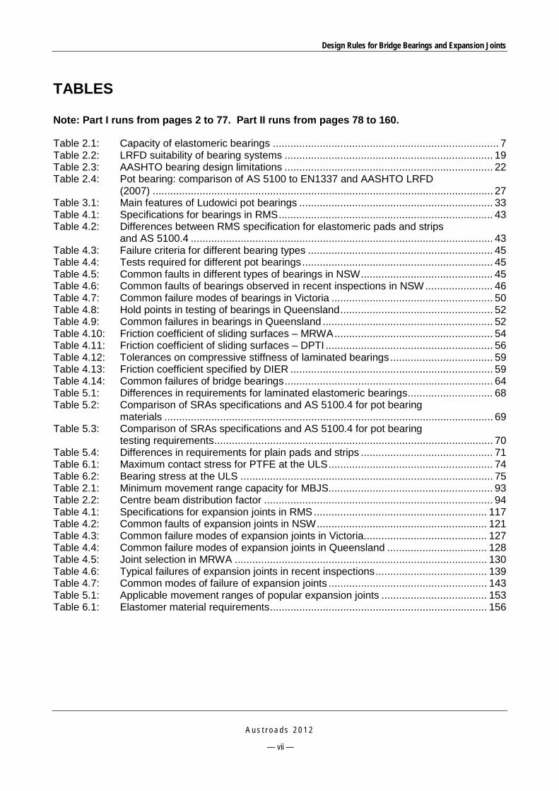
TABLES
Note: Part I runs from pages 2 to 77. Part II runs from pages 78 to 160.
Table 2.1: Capacity of elastomeric bearings ............................................................................. 7 Table 2.2: LRFD suitability of bearing systems ....................................................................... 19 Table 2.3: AASHTO bearing design limitations ....................................................................... 22 Table 2.4: Pot bearing: comparison of AS 5100 to EN1337 and AASHTO LRFD
(2007) .................................................................................................................... 27 Table 3.1: Main features of Ludowici pot bearings .................................................................. 33 Table 4.1: Specifications for bearings in RMS ......................................................................... 43 Table 4.2: Differences between RMS specification for elastomeric pads and strips
and AS 5100.4 ....................................................................................................... 43 Table 4.3: Failure criteria for different bearing types ............................................................... 45 Table 4.4: Tests required for different pot bearings ................................................................. 45 Table 4.5: Common faults in different types of bearings in NSW ............................................. 45 Table 4.6: Common faults of bearings observed in recent inspections in NSW ....................... 46 Table 4.7: Common failure modes of bearings in Victoria ....................................................... 50 Table 4.8: Hold points in testing of bearings in Queensland .................................................... 52 Table 4.9: Common failures in bearings in Queensland .......................................................... 52 Table 4.10: Friction coefficient of sliding surfaces – MRWA ...................................................... 54 Table 4.11: Friction coefficient of sliding surfaces – DPTI ......................................................... 56 Table 4.12: Tolerances on compressive stiffness of laminated bearings ................................... 59 Table 4.13: Friction coefficient specified by DIER ..................................................................... 59 Table 4.14: Common failures of bridge bearings ....................................................................... 64 Table 5.1: Differences in requirements for laminated elastomeric bearings ............................. 68 Table 5.2: Comparison of SRAs specifications and AS 5100.4 for pot bearing
materials ................................................................................................................ 69 Table 5.3: Comparison of SRAs specifications and AS 5100.4 for pot bearing
testing requirements ............................................................................................... 70 Table 5.4: Differences in requirements for plain pads and strips ............................................. 71 Table 6.1: Maximum contact stress for PTFE at the ULS ........................................................ 74 Table 6.2: Bearing stress at the ULS ...................................................................................... 75 Table 2.1: Minimum movement range capacity for MBJS........................................................ 93 Table 2.2: Centre beam distribution factor .............................................................................. 94 Table 4.1: Specifications for expansion joints in RMS ........................................................... 117 Table 4.2: Common faults of expansion joints in NSW .......................................................... 121 Table 4.3: Common failure modes of expansion joints in Victoria .......................................... 127 Table 4.4: Common failure modes of expansion joints in Queensland .................................. 128 Table 4.5: Joint selection in MRWA ...................................................................................... 130 Table 4.6: Typical failures of expansion joints in recent inspections ...................................... 139 Table 4.7: Common modes of failure of expansion joints ...................................................... 143 Table 5.1: Applicable movement ranges of popular expansion joints .................................... 153 Table 6.1: Elastomer material requirements .......................................................................... 156

Design Rules for Bridge Bearings and Expansion Joints
A u s t r o a d s 2 0 1 2
— viii —
FIGURES
Note: Part I runs from pages 2 to 77. Part II runs from pages 78 to 160.
Figure 2.1: Typical cross-section of a laminated elastomeric bearing ......................................... 7 Figure 2.2: Design basis of elastomeric bearings ....................................................................... 7 Figure 2.3: Pot bearing ............................................................................................................. 10 Figure 2.4: Extrusion of rubber from pot bearing due to broken seal ........................................ 10 Figure 2.5: Fixed pot bearing ................................................................................................... 11 Figure 2.6: Free floating pot bearing ........................................................................................ 12 Figure 2.7: Pot glided bearing .................................................................................................. 12 Figure 2.8: Mechanical bearings .............................................................................................. 15 Figure 2.9: Watson disc bearings ............................................................................................. 16 Figure 2.10: RJW spherical bearings ......................................................................................... 17 Figure 2.11: Maurer Sohne spherical bearings ........................................................................... 17 Figure 3.1: Granor pot bearing ................................................................................................. 28 Figure 3.2: Granor laminated elastomeric bearing .................................................................... 29 Figure 3.3: Disktron bearings imported by Granor .................................................................... 30 Figure 3.4: Ludowici pot bearings............................................................................................. 33 Figure 3.5: Trelleborg bearing pad/strip.................................................................................... 34 Figure 3.6: A general mobile pot bearing .................................................................................. 35 Figure 3.7: Trelleborg laminated elastomeric bearing ............................................................... 35 Figure 3.8: Maurer Sohne spherical bearing ............................................................................ 36 Figure 4.1: Elastomeric pad bearing ......................................................................................... 37 Figure 4.2: Laminated elastomeric bearing .............................................................................. 38 Figure 4.3: A laminated elastomeric bearing used in Queensland ............................................ 38 Figure 4.4: Laminated elastomeric bearing with lateral restraints ............................................. 39 Figure 4.5: Pot type bearings ................................................................................................... 39 Figure 4.6: A pot bearing used in NSW .................................................................................... 40 Figure 4.7: Fixed plate bearings ............................................................................................... 40 Figure 4.8: Sliding plate bearings ............................................................................................. 41 Figure 4.9: A sliding plate bearing in use in QLD – in a bad condition ...................................... 41 Figure 4.10: A fixed rocker bearing ............................................................................................ 41 Figure 4.11: An expansion rocker bearing .................................................................................. 42 Figure 4.12: A rocker bearing used in NSW ............................................................................... 42 Figure 4.13: Mortar pad bearing ................................................................................................. 42 Figure 4.14: Cracking and deterioration of elastomer ................................................................. 46 Figure 4.15: Splitting and bulging of bearing pads ...................................................................... 47 Figure 4.16: Corrosion of a rocker bearing ................................................................................. 47 Figure 4.17: Corrosion and loss of support ................................................................................. 47 Figure 4.18: Corrosion and leakage of rubber ............................................................................ 48 Figure 4.19: Broken seal in pot bearing ...................................................................................... 48 Figure 4.20: Slight bulging of an elastomeric bearing ................................................................. 55 Figure 4.21: Crack in steel roller bearing in Old Mt Barker Overpass bridge .............................. 57 Figure 4.22: Anchor bolt of a plate bearing of Stirling I/C bridge broken down due to
fatigue .................................................................................................................... 57 Figure 4.23: Extrusion of elastomer of a pot bearing in Myall Creek ........................................... 58 Figure 4.24: Extrusion of PTFE of a pot bearing in Two Wells bridge ......................................... 58 Figure 4.25: Failure modes of metal bearings in Bridge 2097 in ACT (1).................................... 61 Figure 4.26: Failure modes of metal bearings in Bridge 2097 in ACT (2).................................... 62

Design Rules for Bridge Bearings and Expansion Joints
A u s t r o a d s 2 0 1 2
— ix —
Figure 4.27: General view of bearing WBEAN1 showing poor mortar pads and vertical curve on bearing base ................................................................................ 62
Figure 4.28: Bearing WBEAN1 showing poor mortar, bearing recessed into abutment top and vertical curve of bearing base ................................................................... 63
Figure 4.29: Bearing WBEAN1 showing minor damage to pads, loss of contact between bearing and top pad and edge of bearing being in the same plane as top and bottom mortar pads ..................................................................... 63
Figure 2.1: Steel sliding plates ................................................................................................. 82 Figure 2.2: Asphaltic plug joint ................................................................................................. 83 Figure 2.3: Pourable sealant joint ............................................................................................. 84 Figure 2.4: Compression seal joint ........................................................................................... 85 Figure 2.5: Strip seal joint ........................................................................................................ 86 Figure 2.6: An example of moulded rubber joint ....................................................................... 87 Figure 2.7: Bonded metal/elastomer joint ................................................................................. 88 Figure 2.8: Finger type expansion joint..................................................................................... 89 Figure 2.9: Example of a modular expansion joint .................................................................... 90 Figure 3.1: Wabo modular joint system .................................................................................... 95 Figure 3.2: ETIC finger joint ..................................................................................................... 96 Figure 3.3: Granor Ausflex strip joint ........................................................................................ 97 Figure 3.4: Components of Granor Ausflex strip joint ............................................................... 97 Figure 3.5: Wabo compression seals ....................................................................................... 98 Figure 3.6: Granor Ausflex compression seal ........................................................................... 99 Figure 3.7: Granor Wizflex expansion joint ............................................................................... 99 Figure 3.8: Two series of Waboflex joints ............................................................................... 100 Figure 3.9: Granor XJS expansion joint .................................................................................. 100 Figure 3.10: Prismo-Thormajoint .............................................................................................. 101 Figure 3.11: Miska bolted-in bridge expansion joint .................................................................. 104 Figure 3.12: Miska cast-in bridge expansion joint ..................................................................... 105 Figure 3.13: Miska compression joint ....................................................................................... 105 Figure 3.14: Miska ZealCrete™ elastomeric concrete .............................................................. 106 Figure 3.15: Maurer Sohne modular joint ................................................................................. 106 Figure 3.16: Maurer swivel-joist expansion joint ....................................................................... 107 Figure 3.17: Two-way obliquely arranged swivel support bars and joist boxes ......................... 107 Figure 3.18: TESA PHS System .............................................................................................. 108 Figure 3.19: TESA strip seal joints ........................................................................................... 108 Figure 3.20: Transflex expansion joints .................................................................................... 109 Figure 4.1: Some types of fixed joints used in Queensland .................................................... 112 Figure 4.2: Sliding steel plate joint .......................................................................................... 113 Figure 4.3: Asphaltic plug joint ............................................................................................... 113 Figure 4.4: Pourable sealant joint used in Queensland .......................................................... 114 Figure 4.5: Sealant joints used in NSW .................................................................................. 114 Figure 4.6: Compression seal joint using steel angles ............................................................ 114 Figure 4.7: A compression seal joint used in NSW ................................................................. 115 Figure 4.8: A strip seal joint used in NSW .............................................................................. 115 Figure 4.9: A bonded metal/elastomer joint used in Western Australia ................................... 116 Figure 4.10: A fingerplate joint used in NSW ............................................................................ 116 Figure 4.11: Maurer Sohne modular expansion joint ................................................................ 117 Figure 4.12: Loss of seal adhesion........................................................................................... 122 Figure 4.13: Spall and debris blocking the joint ........................................................................ 122 Figure 4.14: Loss of adhesion on sides of the compression seal .............................................. 123 Figure 4.15: Spall and loose nut of a compression joint ........................................................... 123 Figure 4.16: Broken anchor bolts and assembly breaking loose ............................................... 124

Design Rules for Bridge Bearings and Expansion Joints
A u s t r o a d s 2 0 1 2
— x —
Figure 4.17: Joint blocked with debris and spalls appearing at joint edges ............................... 124 Figure 4.18: Typical deck joint showing minimum transverse reinforcement ............................ 126 Figure 4.19: Wabo joint filled with debris .................................................................................. 130 Figure 4.20: Damaged section of steel angle in a compression seal joint ................................. 131 Figure 4.21: Damaged seal in deck joint .................................................................................. 131 Figure 4.22: Missing seal in deck joint ...................................................................................... 131 Figure 4.23: Failures of a metal fingers-bonded to elastomer joint in Shelley bridge
No. 931 in WA ...................................................................................................... 132 Figure 4.24: Failures of fingerplate type joints in Mt Henry bridge, WA .................................... 133 Figure 4.25: A strip seal on Craig Gilbert bridge, bolts were loosened ..................................... 135 Figure 4.26: A Granor XJS joint with silicone seal failure ......................................................... 136 Figure 4.27: A Felspan joint with debonded rubber .................................................................. 136 Figure 4.28: Damaged asphaltic plug joint in Bridge 1056, cracks along the edges ................. 139 Figure 4.29: A compression seal joint with concrete nosing in Bridge 1147,
deteriorated seal and damaged nosings ............................................................... 139 Figure 4.30: A compression seal joint with steel angles in Bridge 1249, protrusion of
and minor damage/wear to compression seals..................................................... 140 Figure 4.31: An XJS joint in Bridge 2097, cracked nosings ...................................................... 140 Figure 4.32: A Felspan joint in Bridge 2097, damaged joint and missing sections .................... 140 Figure 4.33: A mechanical finger joint in Bridge 2113, a male finger joint segment
broken out ............................................................................................................ 141 Figure 4.34: A deteriorated Transflex joint in Bridge 4087 ........................................................ 141

Design Rules for Bridge Bearings and Expansion Joints
A u s t r o a d s 2 0 1 2
— xi —
SUMMARY
In modern bridge structures, bridge bearings and expansion joints are commonly the source of most maintenance and performance issues. In some situations their performance can lead to the closure/failure of major structures and their maintenance can be extremely difficult and costly to implement. Most of these problems can be overcome if robust design and installation rules are implemented to ensure their design and construction deliver highly durable and reliable components, and that the lessons learnt from practice are fully addressed in the future design and maintenance of these components, thus leading to improved performance.
The report includes the following key topics:
A literature review that summarises the features, usage and performance of bridge bearings and expansion joints throughout the world. The common failures and the proposed solutions to rectify the failures of the most used bearings and expansion joints are discussed.
Information on the State Road Authorities’ current practice in design, installation and maintenance of bridge bearings and expansion joints. Common failure modes of various types of bearing and expansion joint are derived; the key issues in design, manufacture, construction and maintenance of bridge bearings and expansion joints are presented.
Information on the current practice in manufacture and supply of bridge bearings and expansion joints of Australian providers. The manufacturers’ recommendations on the solutions to rectifying the identified failures are provided.
An investigation into failures of some common bridge bearing and expansion joint types that have been used in the past and will be continued in new bridge designs. The outcomes of the investigation are incorporated into proposed changes to the current version of the Australian Bridge Design Standard AS 5100 part 4, and recommendations are provided for the design of bearing and expansion joints.
A generic specification for new bridge bearing types – spherical and disc bearings – to be introduced in Australian practice, and a generic specification for bridge expansion joints in which specific provisions for several popular expansion joint types are also provided.
The fact that each State Road Authority has developed and/or used its own technical guidelines and specifications has brought in a level of inconsistency in the current practice throughout the country. The report also provides recommendations on future directions to overcome this issue.
Design Rules for Bridge Bearings and Expansion Joints
A u s t r o a d s 2 0 1 2
— 1 —
INTRODUCTION
1.1 Background In modern bridge structures, bridge bearings and expansion joints are commonly the source of most maintenance and performance issues. In some situations their performance can lead to the closure/failure of major structures, and their maintenance can be extremely difficult and costly to implement. Most of these problems can be overcome if robust design rules are implemented to ensure their design and construction delivers highly durable and reliable bridge components, and that designers make due allowance for their future maintenance so that it can be undertaken in an acceptable and affordable manner.
The project was conceived to develop such guidelines for the design and construction of both bridge bearings and bridge expansion joints to overcome performance issues experienced in Australian bridges. The primary objective is to obtain failure modes of bearings and joints experienced throughout Australia and develop design, construction and/or maintenance solutions to overcome these issues.
1.2 Aims The aims of the overall research project are to:
Review existing Australian and International literature on bridge bearings and expansion joints.
Collect and report State Road Authority (SRA) experiences with the design, construction inspection, maintenance, repair and failures of all types of bridge bearings and expansion joints.
Develop Austroads guidelines addressing critical issues in the maintenance of existing types of bridge bearings and expansion joints and investigate the introduction of new types of bridge bearings.
Identify specific research and development investigations that will deliver the data relevant to understanding the performance of these structures in the Australian environment.
1.3 Scope Bridge bearings and expansion joints specifically designed for seismic requirements or used for special bridge structures are out of scope of this project.
1.4 Outline This report includes two parts: Part I – Bridge Bearings and Part II – Bridge Expansion Joints. The structure of the two parts is identical.

Design Rules for Bridge Bearings and Expansion Joints
A u s t r o a d s 2 0 1 2
— 2 —
PART I – BRIDGE BEARINGS

Design Rules for Bridge Bearings and Expansion Joints
A u s t r o a d s 2 0 1 2
— 3 —
1 INTRODUCTION The contents of Part I – Bridge Bearings are briefly summarised below.
Section 2 presents a literature review that summarises the features, usage and performance of bridge bearings throughout the world. Thus, the common failures of the common type of bearings are identified.
Section 3 describes the current practice in manufacture and supply of bridge bearings of some popular Australian providers.
Section 4 describes SRAs’ experience in design, installation and maintenance of bridge bearings. Common failure modes of various types of bearing are derived from SRAs’ information, based on which the key issues in design, manufacture, construction and maintenance of bridge bearings are identified.
Section 5 presents an investigation into failures of some common bridge bearing types that have been used in the past and will be continued in new bridge designs, and proposes changes to the current version of the Australian Bridge Design Standard AS 5100 part 4. Proposed changes for other bearing types are also addressed in this section.
Section 6 proposes a generic specification for new types of bridge bearing to be introduced in Australia practice – spherical and disc bearings.
Section 7 represents the key conclusions arising from the project.

Design Rules for Bridge Bearings and Expansion Joints
A u s t r o a d s 2 0 1 2
— 4 —
2 LITERATURE REVIEW ON BRIDGE BEARINGS
2.1 General 2.1.1 Historical Development By the end of the 18th century the first bridge structures were built from stone, brick or masonry, which have massive volumes and undergo slight movements due to external impact or thermal changes. The slight movements are accommodated by deformation of the materials or by small displacements of the supports. Thus there were no bearings used in these structures.
The concept of bearings was introduced in the 19th century when cast iron and steel materials were used in bridge construction. Longer span bridges made use of flexible supports to accommodate the contraction and expansion movements at support points due to temperature changes. The first types of bearing were metal plates sliding on one another, or roller bearings. These bearings were popular for a century in steel bridges.
In the 20th century, with the booming construction and development of infrastructure and the development of advanced technologies, more slender bridge structures were built, including large span prestressed concrete bridges. These structures require bearing devices that can accommodate larger rotational and translational movements. As a result, new materials for bearings were introduced, including rubber and a combination of rubber and steel laminates.
In 1932 French railways were the first to make use of rubber pads on a railway bridge at La Plaine St Denis in Paris by placing them underneath steel bearings to absorb vibration.
It was Eugene Freyssinet who first combined rubber and steel into a single product to strengthen the bearing capacity of rubber. In 1952, the first rubber-steel bearings were manufactured by Freyssinet that consisted of a stack of elastomer layers and sheets of tinned metal grillage. The metal grillage was replaced by steel plates in 1956 when the first laminated elastomeric bearings were manufactured (Raina 1994).
Rapid developments in bearing materials in subsequent years resulted in the introduction of neoprene – elastomer compounds for bearings in severe climate conditions, the use of stainless steel to resist corrosion in aggressive environments, and the discovery of polytetrafluoroethylene (PTFE) sliding sheets that allow large movement capability for the bearings. Thus, more sophisticated bearing systems were introduced, including pot bearings, and later on, spherical and disc bearings. These bearings can sustain large loads and accommodate multi-directional movements, and can typically meet the requirements of modern bridges with complex actions, such as very wide, large span, multi-span and skew or curve bridges, etc.
In Australia, bridge works are carried out under the authority of independently operated State Road Authorities in the eight states and territories. The previous Austroads Bridge Design Code (Austroads 1992) sets out the requirements for design, manufacture, testing and installation of the most common types of bearings, including mechanical bearings, elastomeric bearings and pot bearings. AS 5100, which was in effect in 2004, added some provisions regarding design criteria for pot bearings and sliding contact surfaces at the ultimate limit states (ULS) as well as testing of elastomer and laminated elastomeric bearings. However, no provisions have been made towards the implementation of spherical and disc bearings.

Design Rules for Bridge Bearings and Expansion Joints
A u s t r o a d s 2 0 1 2
— 5 —
2.1.2 Functions of Bridge Bearings In bridge structures, bearings are the connections between the superstructure and the substructure. They not only transfer loads from superstructure to substructure, but also ensure the structure functions as intended so that no part is under excessive stress and/or deformation. In typical girder bridges, the bearings must allow free translations and rotations of the span in the specified directions. In addition, bearings must also restraint the span in predetermined positions or directions.
2.1.3 General Design Considerations Design life
In most of the bridge design codes, bearings are specified to have the same design life as the bridge structure, including long life metallic and non-metallic materials. Experiences from all over the world, however, have shown that bearings of all types have failure modes caused by various factors relating to all stages of the bearing life such as manufacture, installation or maintenance. The failures may occur on any part of the bearing such as the bearing itself, clamping plates or anchor bolts. This leads to the requirements of repair or replacement of the bearing in whole or in part during its service life. Provisions should be made regarding the replaceability of the bearing, including the method of removal, jacking points and loads. Special considerations should be given to jacking space especially for slab type bridges using halving joints, or bridges with possible differential settlements, etc. (Austroads 2009, Lee 1994).
Durability
Corrosion of metal bearing components is one of the most common causes of bearing failures. Thus provisions should be made to avoid corrosion, particularly in aggressive conditions, such as use of stainless steel, use of materials having similar electrode potentials and detailing the bearing in such a way that it does not trap moisture or dirt.
Earthquake design
The capacity of bearings to resist horizontal loads such as earthquake loads should be considered in the design. Restraint can be provided by means of separate dowels or special keys.
Other considerations
A variety of other factors such as spreader plates, uplift, and limit states should be considered in the bearing design, as follows:
Spreader plates: the spreader plates of bearings should be so proportioned so that concentrated loads are sufficiently distributed to ensure that the permissible pressures on the adjacent bridge structure are not exceeded (Raina 1994).
Uplift: if the bearings will be subjected to uplift, they and their fixings must be designed to limit separation of the parts. In particular, rubber should not be allowed to go into tension and sliding surfaces should not be allowed to separate. This would allow dust, grit and other abrasive or corrosive materials to enter and affect the sliding surface (Lee 1994).
Limit states: the bearings should not suffer damage that would affect their proper functioning or incur excessive maintenance during their working life to meet the serviceability limit state (SLS). To meet the ULS, the strength and stability of the bearings should be adequate to withstand the ultimate design loads and movements of the structure (Lee 1994).

Design Rules for Bridge Bearings and Expansion Joints
A u s t r o a d s 2 0 1 2
— 6 —
2.2 Common Types of Bridge Bearings 2.2.1 Elastomeric Bearings General features
Being first used in the UK in 1956 and in the USA in 1960 (Fyfe et al. 2006), elastomeric bearings are one of the most popular types of bearings used nowadays for pre-stressed planks, girders and troughs and steel girder spans up to 40 m.
These types of bearings can meet a number of requirements such as capability of translational movement in both longitudinal and transverse directions, rotational movement and vibration isolation for the superstructure. In addition, they have a number of advantages including low cost, ease of installation, long service life, low maintenance, and corrosion protection. Due to high resistance to rotation, they are, however, unsuitable under high rotation or excessive longitudinal movement with low compressive load.
Combined with an effective method of anchoring via friction or dowels through the bearing, elastomeric bearings provide a system that can be used in a wide range of applications. There exist two common bearing forms:
Fixed bearings – when the horizontal movement is restrained by the use of steel dowels that extend from the superstructure, through holes in the bearing to the substructure. Alternatively, the superstructure can be fixed to the substructure by separate fixtures to provide restraint.
Expansion bearings – the horizontal movement in an elastomeric bearing occurs by the shearing of the rubber such that the top of the bearing moves relative to the bottom of the bearing. Internal or external restraints should be provided to ensure the bearings do not ‘walk out’.
Elastomeric bearings include three types, being plain pads, plain strips and laminated elastomeric bearings (LEB) and are used as follows:
Continuous strip bearings of plain elastomer up to 125 x 25 mm in cross-section, which are used to support slabs and pre-stressed concrete planks.
Plain elastomeric bearing pads, having varying thicknesses up to 25 mm, are used to support pre-stressed concrete planks and short span girders where individual bearing supports are required. They are usually rectangular but can also be specified or used as circular. The advantage of circular bearings is that they have uniform characteristics in all directions. This is particularly useful on skew bridges to accommodate the pier movements not along the bridge. These bearings have limited vertical load capacity, shear movement and rotational capacities compared to the thicker laminated bearings described below.
LEB pads are either rectangular up to 600 mm x 600 mm x 293 mm thick or circular up to 880 mm diameter x 309 mm thick (Figure 2.1) and are used to support pre-stressed concrete girders, troughs and steel girders up to 40 m spans. The bearings consist of elastomer reinforced by a number of embedded steel plates. The number of plates and the height of the bearing increase as the bearing capacity and/or movement range increases.

Design Rules for Bridge Bearings and Expansion Joints
A u s t r o a d s 2 0 1 2
— 7 —
Source: Austroads (2009).
Figure 2.1: Typical cross-section of a laminated elastomeric bearing
The capacity of the above three types of elastomeric bearings is listed in Table 2.1.
Table 2.1: Capacity of elastomeric bearings
Bearing type Maximum vertical force (kN)
Maximum translation (mm)
Maximum rotation (rad)
Plain pads Strips 1500 15 0.01
Laminated elastomeric bearings 5000 100 0.04 Source: Lee (1994).
Design basis
The design of elastomeric bearings is based on a limit on the combined effects of compressive strain, shear strain and rotational strain (Figure 2.2).
Source: Austroads (2009).
Figure 2.2: Design basis of elastomeric bearings
The proper performance of an expansion elastomeric bearing is contingent on sufficient friction being developed between the bearing and the top and bottom interface material. If the friction is inadequate the bearing will ‘walk out’ over time as the bearing resets to vertical after each

Design Rules for Bridge Bearings and Expansion Joints
A u s t r o a d s 2 0 1 2
— 8 —
successive shearing movement. It is for this reason that the use of neat epoxy resin on the bearing support is not permitted.
Materials
For elastomer manufacture, natural rubber is specified in AASHTO LRFD, BS 5400 and AS 5100.
Synthetic rubbers such as neoprene and chlorobutyl are also used. Although the material is cheaper, it has some disadvantages compared to natural rubber such as poor ratio of elastic modulus to shear modulus, poorer performance and brittleness at low temperatures (neoprene). Chlorobutyl, however, has good abrasion resistance.
Selection of natural or synthetic rubber depends on the site conditions. The selected rubber should have good resistance to the actions of oils, weather, atmospheric ozone, and extreme temperatures. For example, when the lowest temperature is -10 °C then natural rubber is selected, when the highest likely temperature is 60 °C or when oil or grease may be present, chloroprene is a suitable choice (Lee 1994).
Beside steel reinforced bearings, cotton fabric reinforced (cotton duck) bearings and fibre reinforced bearings have been introduced (Gase & Kaczinski, 2006). The former are stiff against shear and rotation and can accommodate high compressive loads, thus are commonly used with a PTFE sliding surface, while the latter have not proven to offer an economical advantage over the steel reinforced bearings.
Common faults/defects
The following failure modes have been reported in the literature (Fyfe et al. 2006):
cracking of elastomer
excessive bulging or splitting under vertical loads
slippage and irregular contact of the bearing surfaces
migration of bearings from their original as placed seat
changes in rubber properties with aging
ozone cracking.
Recommendations
The following summary of the performance aspects of elastomeric bearings was presented in Austroads (2001):
Although elastomeric bearings have performed well, provisions for jacking and re-positioning should be made due to the long-term creep and shrinkage shortening.
Elastomeric bearings are the first choice of bearings for most small to medium span bridges.
These bearings are not recommended when small loads are coupled with considerable longitudinal movements, for instance, for end spans of continuous bridges.

Design Rules for Bridge Bearings and Expansion Joints
A u s t r o a d s 2 0 1 2
— 9 —
Construction issues
In the installation of elastomeric bearings the following issues need to be addressed:
The mortar pad must be planar to ensure uniform bearing and the plan dimensions of the mortar pad must exceed the plan dimension of the bearing to ensure a clearance of at least 25 mm. This is to ensure friction is developed to prevent curling of the edges of the bearing that may lead to tearing of the elastomer.
The safety and stability of tall bearings. The use of tall LEBs to support individual girders presents a stability issue and therefore a safety issue during construction as they may be unstable in terms of rotation and shearing until the in situ deck is constructed. To address this issue, temporary restraints must be provided to prevent the girders sliding off the bearings or rotating and falling. The temporary supports must be fixed before the girder is released from the lifting mechanism.
Effect of crossfall
If girders are placed normal to the deck crossfall the deflection of the girder will have a vertical and a horizontal component. The horizontal displacement may cause the centre of gravity to shift to the point where the girder becomes unstable. The design of the temporary bracing should take this into account, if applicable.
Thermal effects
The stability of bearings and girders can also be affected by thermal effects. Solar heating of one side of a girder may cause the member to bow with the possibility of the centre of gravity shifting horizontally to the point where the girder becomes unstable. To address this issue, temporary restraints must be provided to prevent the girders sliding off the bearings or rotating and falling. The temporary supports must be fixed before the girder is released from the lifting mechanism.
When the member is placed on the bearing a close inspection should be carried out to ensure uniform seating. Rotation of the member under the subsequent dead load of the deck concrete will correct the situation to some degree. However, if a significant gap exists between the bearing and the member, remedial measures will need to be taken. This may involve correcting the levels on the mortar pad.
Laminated bearings under load result in a minor rippling of the vertical surface. Excessive rippling on one side of a bearing compared to the other indicates unequal loading and may lead to splitting of the protruding rubber. Remedial action may be required to address the issue.
Uneven loading of elastomeric bearings results in differential compressive strains and may require remedial action.
2.2.2 Pot Bearings General features
Developed around 50 years ago, pot bearings have been used extensively for large bearings and have load capacities from 1200 to 10 000 kN. They consist of a cylindrical pad of rubber contained in a steel pot attached to, or integral with, a top plate. A close fitting steel piston attached to, or integral with, a bottom plate bears on the rubber pad. The pressure in pot bearings is in the range of 40-50 MPa.

Design Rules for Bridge Bearings and Expansion Joints
A u s t r o a d s 2 0 1 2
— 10 —
When rubber is confined in this way under pressure it acts as a fluid and as a result the top plate of the bearing can rock on the pad in any direction. The rubber pad has a number of circumferential bronze sealing rings that are vulcanised or recessed into the top of the rubber (Figure 2.3).
Source: Austroads (2009).
Figure 2.3: Pot bearing
The purpose of the rings is to prevent the extrusion of the rubber from the pot. Instances have occurred where the rubber pad has extruded out of the pot as a result of either excessive clearance between the rings and the internal diameter of the pot or an insufficient number of sealing rings (Figure 2.4).
Source: Austroads (2009).
Figure 2.4: Extrusion of rubber from pot bearing due to broken seal
When load is applied to the bearing, the rubber pad expands and the sealing rings bear against the vertical face of the pot creating the seal. The maximum permitted clearance between the pot and the piston is 1 mm. Pot bearings are much thinner in height compared to bearings used in the past and are ideal as replacement bearings on older bridges.

Design Rules for Bridge Bearings and Expansion Joints
A u s t r o a d s 2 0 1 2
— 11 —
Pot bearings are able to support large compressive loads, but the elastomer may leak and the sealing rings may suffer wear or damage (Roeder et al. 1995).
Fixed pot bearings
For fixed pot bearings the bottom plate is fixed to the superstructure by bolting the pot section to a plate cast into the member. Similarly the bottom plate is fixed to the headstock by bolting the piston section to a plate cast into the member. In each case the clearance between the cast-in plates must be sufficient to allow the bolts to be removed to facilitate any future replacement of the bearing (Figure 2.5).
Source: Austroads (2009).
Figure 2.5: Fixed pot bearing
Expansion pot bearings
In expansion pot bearings a thin disc of PTFE is placed into a recess at the top of the pot. A third plate bolted to the superstructure is faced on the bottom with a sheet of polished stainless steel that can slide back and forth on the PTFE disc. As the PTFE has very low friction (coefficient of friction 0.01-0.015) under load, this type of bearing offers very little resistance to the movements of the superstructure. Current standards require that the PTFE discs be dimpled to provide a reservoir for a lubricant applied during manufacture.
The range of sliding movement of a bearing is only limited by the length of the top sliding plate. Similar to fixed bearings, the bottom plate of expansion bearings is fixed to the superstructure by bolting the pot section to a plate cast into the member. The bottom plate is fixed to the headstock by bolting the piston section to a plate cast into the member. In each case the clearance between the cast-in plates must be sufficient to allow the bolts to be removed to facilitate any future replacement of the bearing (Figure 2.6).
Expansion pot bearings are available in two forms – the free sliding/free floating bearing (Figure 2.6) or the glided sliding bearing (Figure 2.7).

Design Rules for Bridge Bearings and Expansion Joints
A u s t r o a d s 2 0 1 2
— 12 —
Source: Austroads (2009).
Figure 2.6: Free floating pot bearing
Source: Austroads (2009).
Figure 2.7: Pot glided bearing
The free sliding bearing is used where the designer wants the bridge to be able to slide in all directions. The guided sliding bearing is used where lateral restraint of the superstructure is required and also to ‘guide’ the direction of movement.
The guides are bolted to the sliding plate. In instances where future lateral movement of piers is anticipated e.g. mining subsidence, provision can be made for the replacement of the guides with wider or narrower guide plates to suit the situation.
A combination of a free sliding bearing and a guided sliding bearing is often specified on curved bridges to ensure the bridge is provided with free movement.
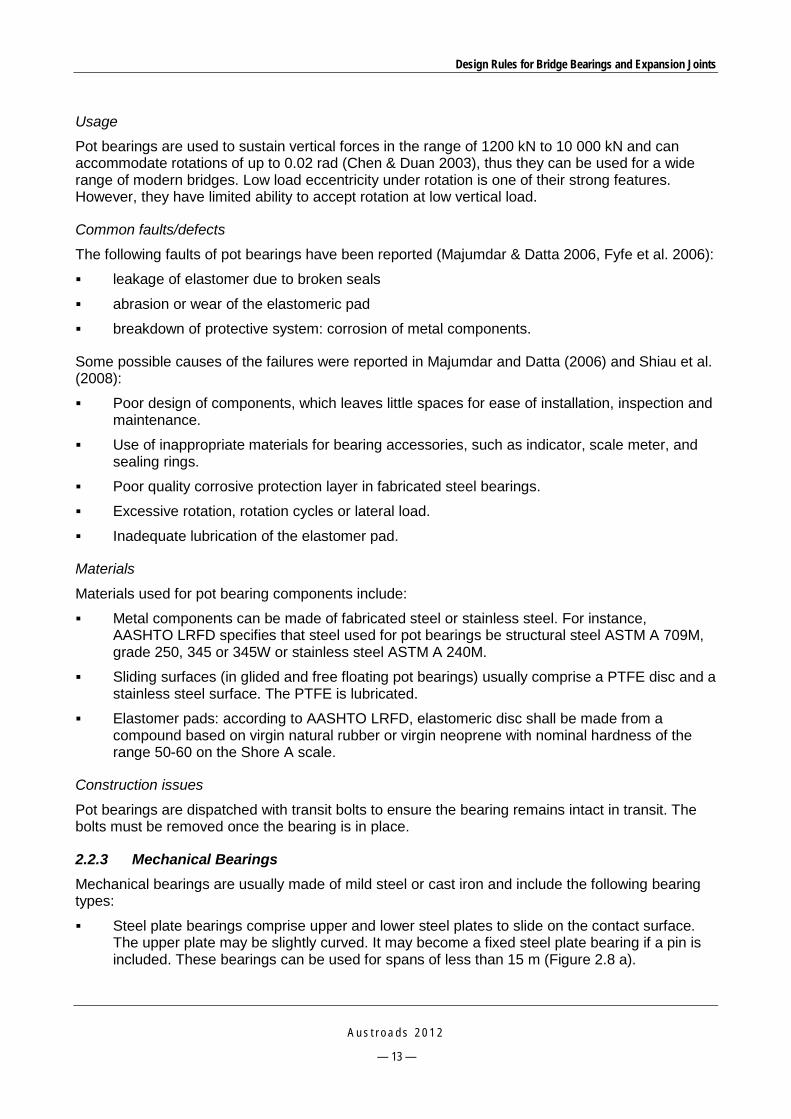
Design Rules for Bridge Bearings and Expansion Joints
A u s t r o a d s 2 0 1 2
— 13 —
Usage
Pot bearings are used to sustain vertical forces in the range of 1200 kN to 10 000 kN and can accommodate rotations of up to 0.02 rad (Chen & Duan 2003), thus they can be used for a wide range of modern bridges. Low load eccentricity under rotation is one of their strong features. However, they have limited ability to accept rotation at low vertical load.
Common faults/defects
The following faults of pot bearings have been reported (Majumdar & Datta 2006, Fyfe et al. 2006):
leakage of elastomer due to broken seals
abrasion or wear of the elastomeric pad
breakdown of protective system: corrosion of metal components.
Some possible causes of the failures were reported in Majumdar and Datta (2006) and Shiau et al. (2008):
Poor design of components, which leaves little spaces for ease of installation, inspection and maintenance.
Use of inappropriate materials for bearing accessories, such as indicator, scale meter, and sealing rings.
Poor quality corrosive protection layer in fabricated steel bearings.
Excessive rotation, rotation cycles or lateral load.
Inadequate lubrication of the elastomer pad.
Materials
Materials used for pot bearing components include:
Metal components can be made of fabricated steel or stainless steel. For instance, AASHTO LRFD specifies that steel used for pot bearings be structural steel ASTM A 709M, grade 250, 345 or 345W or stainless steel ASTM A 240M.
Sliding surfaces (in glided and free floating pot bearings) usually comprise a PTFE disc and a stainless steel surface. The PTFE is lubricated.
Elastomer pads: according to AASHTO LRFD, elastomeric disc shall be made from a compound based on virgin natural rubber or virgin neoprene with nominal hardness of the range 50-60 on the Shore A scale.
Construction issues
Pot bearings are dispatched with transit bolts to ensure the bearing remains intact in transit. The bolts must be removed once the bearing is in place.
2.2.3 Mechanical Bearings Mechanical bearings are usually made of mild steel or cast iron and include the following bearing types:
Steel plate bearings comprise upper and lower steel plates to slide on the contact surface. The upper plate may be slightly curved. It may become a fixed steel plate bearing if a pin is included. These bearings can be used for spans of less than 15 m (Figure 2.8 a).

Design Rules for Bridge Bearings and Expansion Joints
A u s t r o a d s 2 0 1 2
— 14 —
Rocker bearings comprise a curved surface in contact with a flat or another curved surface and constrained to prevent relative horizontal movement. The curve surface may be cylindrical or spherical. The rotation is allowed by rolling of one part on another (Figure 2.8 b, c).
Roller bearings consist of one or more steel cylinders between parallel upper and lower steel plates. Single roller bearings can accommodate rotational movements about the roller’s axis and translational movements in the perpendicular direction with the axis. Multiple roller bearings can only provide translational movement, but can also permit rotation by adding another element such as a rocker or knuckle bearing. These bearings can be seen in large span steel truss bridges (Figure 2.8 d, e, f).
Knuckle bearings are another type of rocker bearing. They include two or more members with mating curved surfaces, which may be spherical or cylindrical. Another form is the pin type, where the upper and the lower plates have a concave cylindrical surface mating with a core pin. Knuckle bearings permit rotation by rolling on the contact surface (Figure 2.8 g, h, i).
Leaf bearings consist of a pin passing through a number of interleaved plates fixed alternatively to the upper and lower outer bearing plates. Pin bearings permit only rotational movement, but can be used in combination with roller bearings to provide rotation and translation. Uplift can be accommodated by this type of bearing (Figure 2.8 i).
Common faults/defects
A number of failure modes have been reported in the literature (Austroads 2001, Fyfe et al. 2006); they include:
The main problem has been corrosion of the steel, particularly at the sliding interfaces leading to a frozen bearing. Roller or rocker bearings fabricated with stainless steel components including bolts are generally free of corrosion.
Cracking and spalling of mortar or concrete under the bearing plate.
Frozen bearings (rocker, roller, sliding plates).
There was a catastrophic failure of rocker bearings in the USA where a domino collapse of four spans occurred due to the rockers becoming unstable at fairly mild angles of tilt. It is recommended that this type of bearing not be used on modern bridges (Fyfe et al. 2006).
Mechanical cylindrical, rocker and roller bearings can only perform satisfactorily if the ‘door hinge’ analogy is followed, that is, if all hinges are in line. Thus those bearings should not be used for skew bridges (Fyfe et al. 2006).
The metal-to-metal contacts in metal bearings easily trap dirt and moisture, thus causing corrosion and leading to freezing of bearing components, which is one of the most common failures of this type of bearing. Lubricants have been used and found to trap debris and moisture and also cause corrosion to develop. Mechanical bearings should not be used for new bridge designs (Gase & Kaczinski 2006). Where practical, metal bearings should only be considered for fixed bearing types (AASHTO & NSBA 2005).

Design Rules for Bridge Bearings and Expansion Joints
A u s t r o a d s 2 0 1 2
— 15 —
Source: Raina VK (1994).
Figure 2.8: Mechanical bearings
a – Sliding plates
Bottom plate Top sliding plate
b – Single roller bearing c – Multiple roller bearing
h – Knuckle pin bearing i – Knuckle leaf bearing
f – Point spherical rocker bearing g – Spherical knuckle bearing
d – Linear spherical rocker bearing e – Cylindrical rocker bearing
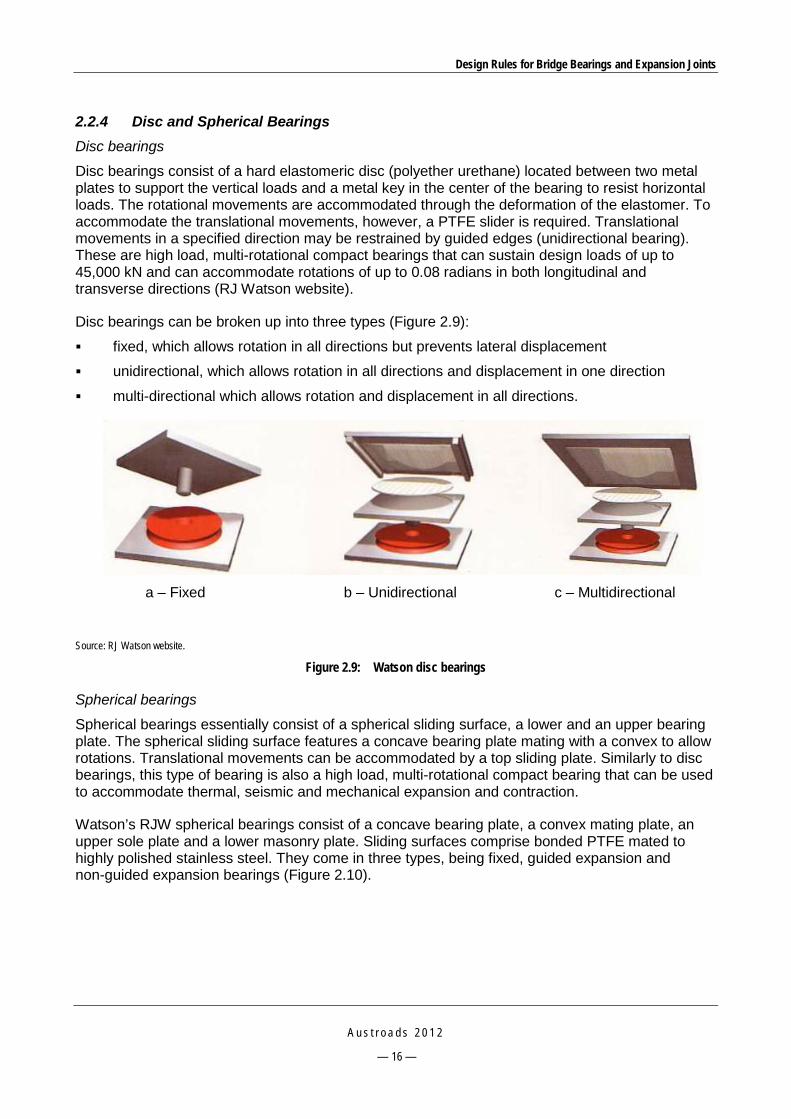
Design Rules for Bridge Bearings and Expansion Joints
A u s t r o a d s 2 0 1 2
— 16 —
2.2.4 Disc and Spherical Bearings Disc bearings
Disc bearings consist of a hard elastomeric disc (polyether urethane) located between two metal plates to support the vertical loads and a metal key in the center of the bearing to resist horizontal loads. The rotational movements are accommodated through the deformation of the elastomer. To accommodate the translational movements, however, a PTFE slider is required. Translational movements in a specified direction may be restrained by guided edges (unidirectional bearing). These are high load, multi-rotational compact bearings that can sustain design loads of up to 45,000 kN and can accommodate rotations of up to 0.08 radians in both longitudinal and transverse directions (RJ Watson website).
Disc bearings can be broken up into three types (Figure 2.9):
fixed, which allows rotation in all directions but prevents lateral displacement
unidirectional, which allows rotation in all directions and displacement in one direction
multi-directional which allows rotation and displacement in all directions.
Source: RJ Watson website.
Figure 2.9: Watson disc bearings
Spherical bearings
Spherical bearings essentially consist of a spherical sliding surface, a lower and an upper bearing plate. The spherical sliding surface features a concave bearing plate mating with a convex to allow rotations. Translational movements can be accommodated by a top sliding plate. Similarly to disc bearings, this type of bearing is also a high load, multi-rotational compact bearing that can be used to accommodate thermal, seismic and mechanical expansion and contraction.
Watson’s RJW spherical bearings consist of a concave bearing plate, a convex mating plate, an upper sole plate and a lower masonry plate. Sliding surfaces comprise bonded PTFE mated to highly polished stainless steel. They come in three types, being fixed, guided expansion and non-guided expansion bearings (Figure 2.10).
a – Fixed b – Unidirectional c – Multidirectional
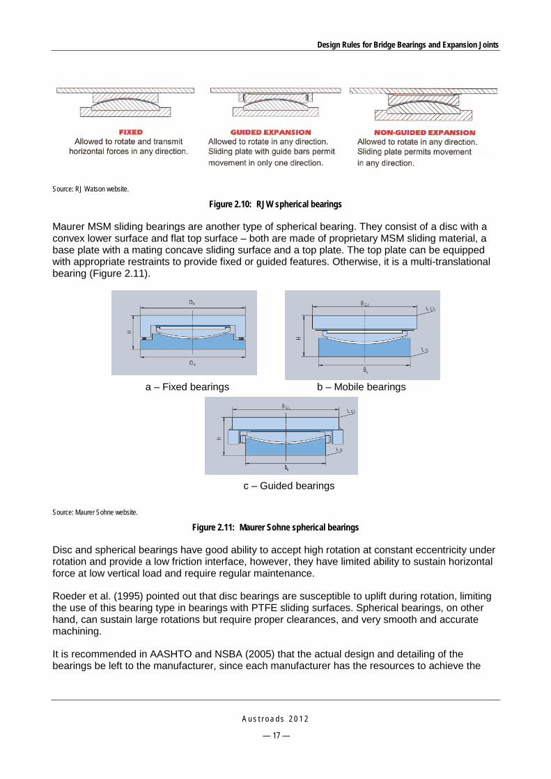
Design Rules for Bridge Bearings and Expansion Joints
A u s t r o a d s 2 0 1 2
— 17 —
Source: RJ Watson website.
Figure 2.10: RJW spherical bearings
Maurer MSM sliding bearings are another type of spherical bearing. They consist of a disc with a convex lower surface and flat top surface – both are made of proprietary MSM sliding material, a base plate with a mating concave sliding surface and a top plate. The top plate can be equipped with appropriate restraints to provide fixed or guided features. Otherwise, it is a multi-translational bearing (Figure 2.11).
Source: Maurer Sohne website.
Figure 2.11: Maurer Sohne spherical bearings
Disc and spherical bearings have good ability to accept high rotation at constant eccentricity under rotation and provide a low friction interface, however, they have limited ability to sustain horizontal force at low vertical load and require regular maintenance.
Roeder et al. (1995) pointed out that disc bearings are susceptible to uplift during rotation, limiting the use of this bearing type in bearings with PTFE sliding surfaces. Spherical bearings, on other hand, can sustain large rotations but require proper clearances, and very smooth and accurate machining.
It is recommended in AASHTO and NSBA (2005) that the actual design and detailing of the bearings be left to the manufacturer, since each manufacturer has the resources to achieve the
a – Fixed bearings b – Mobile bearings
c – Guided bearings

Design Rules for Bridge Bearings and Expansion Joints
A u s t r o a d s 2 0 1 2
— 18 —
greatest economy in bearing construction. The engineer just specifies the loads and geometric requirements for the bearing.
Common faults/defects
The following modes of failure of spherical bearings have been reported (Austroads 2001):
breakdown of protective system
missing bolts
indentation and deformation of metal plates
sliding interface problems.
Disc bearings were first used in Canada in 1970 and in the USA in 1972. Since then early installations have proven to perform well without any distress reported (Fyfe et al. 2006).
2.2.5 General Causes of Bearing Failure A number of root causes of bearing failures are discussed in various publications such as Fyfe et al. (2006), Austroads (2001), and Raina (1994), being:
Movement-related failures: movements due to temperature gradients, post-tensioning, etc. not accurately addressed.
Bridge geometry-related failures: misalignment or improper orientation of the bearing with respect to direction of movement.
Excessive non-thermal induced movements of piers and abutments.
Design – inadequate access.
Manufacture – fabrication tolerance errors.
Construction (major source): inadequate or improper installation of bearings, or disintegration of poorly prepared bearing seatings including the bedding anchorage, setting/releasing of transit bolts where applicable, cleaning of epoxy mortar splashes or other deleterious materials.
Maintenance: accumulation of detritus and water.
Failure of the expansion joint system that leads to water leaking to underneath the bearings.
Uneven loading on bearings of skew bridges.
Attack by chemicals, fire, corrosion and unforeseen events (impacts).
Bedding mortar: cracking of mortar and gaps between mortar and bearing.
2.3 Design Codes/Specifications 2.3.1 AASHTO LRFD Bridge Design Specification Table 2.2 presents information from the AASHTO LRFD specifications on the suitability of bearings regarding the movement, rotation and load capacity in three main directions.

Design Rules for Bridge Bearings and Expansion Joints
A u s t r o a d s 2 0 1 2
— 19 —
Table 2.2: LRFD suitability of bearing systems
Type of bearing Movement Rotation about bridge
axis indicated Resistance to loads
Long. Trans. Long. Trans. Vert. Long. Trans. Vert.
Plain elastomeric pad S S S S L L L L
Fiberglass-reinforced pad S S S S L L L L
Cotton-duck-reinforced pad U U U U U L L S
Steel-reinforced elastomeric bearing S S S S L L L S
Plane sliding bearing S S U U S R R S
Curved sliding spherical bearing R R S S S R R S
Curved sliding cylindrical bearing R R U S U R R S
Disc bearing R R S S L S S S
Double cylindrical bearing R R S S U R R S
Pot bearing R R S S L S S S
Rocker bearing S U U S U R R S
Knuckle pinned bearing U U U S U S R S
Single roller bearing S U U S U U R S
Multiple roller bearing S U U U U U U S S = suitable, U = unsuitable, L= suitable for limited applications, R = may be suitable, but requires special considerations or additional elements such as sliders or guide-ways, Long. = longitudinal axis, Trans. = transverse axis, Vert. = vertical axis. Source: AASHTO (2010). The AASHTO LRFD specifications states that the design of bearings to act as fuses or sustain irreparable damage at the extreme event limit state may be allowed by the bridge owner provided that the span is prevented from loss.
Gase and Kaczinski (2006) present the findings of collaborative research work between AASHTO and NSBA (American National Steel Bridge Alliance) carried out in 2005 on the AASHTO LRFD specifications in an effort to provide standardisation of the design and detailing of bridge bearings. They are briefly summarised below.
Bearing types
AASHTO LRFD specifies three bearing categories, being elastomeric bearings, steel bearings and high-load multi-rotational bearings (HLMR).
Elastomeric bearings include plain pads, steel reinforced and cotton duck bearings, as follows:
Plain pads rely upon friction at contact surface to resist bulging. Local slip resulting from friction loss leads to increased strain, which limits load carrying capacity. Allowable stress is a function of shape factor. The pads should be thin to carry maximum compressive load and accommodate only small horizontal translations and rotations.
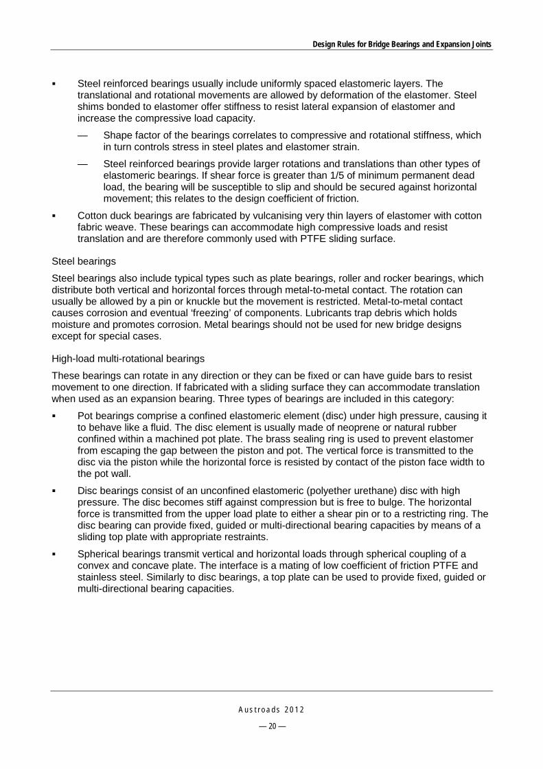
Design Rules for Bridge Bearings and Expansion Joints
A u s t r o a d s 2 0 1 2
— 20 —
Steel reinforced bearings usually include uniformly spaced elastomeric layers. The translational and rotational movements are allowed by deformation of the elastomer. Steel shims bonded to elastomer offer stiffness to resist lateral expansion of elastomer and increase the compressive load capacity.
— Shape factor of the bearings correlates to compressive and rotational stiffness, which in turn controls stress in steel plates and elastomer strain.
— Steel reinforced bearings provide larger rotations and translations than other types of elastomeric bearings. If shear force is greater than 1/5 of minimum permanent dead load, the bearing will be susceptible to slip and should be secured against horizontal movement; this relates to the design coefficient of friction.
Cotton duck bearings are fabricated by vulcanising very thin layers of elastomer with cotton fabric weave. These bearings can accommodate high compressive loads and resist translation and are therefore commonly used with PTFE sliding surface.
Steel bearings
Steel bearings also include typical types such as plate bearings, roller and rocker bearings, which distribute both vertical and horizontal forces through metal-to-metal contact. The rotation can usually be allowed by a pin or knuckle but the movement is restricted. Metal-to-metal contact causes corrosion and eventual ‘freezing’ of components. Lubricants trap debris which holds moisture and promotes corrosion. Metal bearings should not be used for new bridge designs except for special cases.
High-load multi-rotational bearings
These bearings can rotate in any direction or they can be fixed or can have guide bars to resist movement to one direction. If fabricated with a sliding surface they can accommodate translation when used as an expansion bearing. Three types of bearings are included in this category:
Pot bearings comprise a confined elastomeric element (disc) under high pressure, causing it to behave like a fluid. The disc element is usually made of neoprene or natural rubber confined within a machined pot plate. The brass sealing ring is used to prevent elastomer from escaping the gap between the piston and pot. The vertical force is transmitted to the disc via the piston while the horizontal force is resisted by contact of the piston face width to the pot wall.
Disc bearings consist of an unconfined elastomeric (polyether urethane) disc with high pressure. The disc becomes stiff against compression but is free to bulge. The horizontal force is transmitted from the upper load plate to either a shear pin or to a restricting ring. The disc bearing can provide fixed, guided or multi-directional bearing capacities by means of a sliding top plate with appropriate restraints.
Spherical bearings transmit vertical and horizontal loads through spherical coupling of a convex and concave plate. The interface is a mating of low coefficient of friction PTFE and stainless steel. Similarly to disc bearings, a top plate can be used to provide fixed, guided or multi-directional bearing capacities.
Design Rules for Bridge Bearings and Expansion Joints
A u s t r o a d s 2 0 1 2
— 21 —
Bearing design requirements
Design loads, rotation and translation
Elastomeric bearings are designed for unfactored service loads while HLMR bearings are designed for factored service vertical loads in addition to applicable strength and extreme horizontal forces. Steel bearings are designed for the same loads as HLMR bearings, but impact should be included for the vertical loads.
Primary causes of bridge movement are bridge skew, curvature, initial camber or curvature, construction loads, misalignment of construction tolerances, settlement of supports, temperature variation and traffic loads.
Bearing connections and substrate movements should be designed to transfer the forces imparted by the bearings resistance to movement.
Frictional forces of steel bearings and bearings utilising PTFE/stainless steel sliding surfaces should be considered.
Design requirements
Elastomeric bearings are designed by either AASHTO method A or B. Method B allows a maximum compressive stress of 11 MPa for bearings subjected to shear deformations and 12 MPa for fixed bearings. Method A allows 6.9 MPa compressive stresses regardless of style. All other elastomeric bearings are designed under method A. The following requirements are specified:
Shear modulus (G) is the most important material property for design of elastomeric bearings. Designers should use minimum and maximum values of G for various hardnesses.
Designers should account for the initial offset due to varying temperatures at the time of installation by multiplying the design translation by a minimum factor of safety of 1.5 or ensure that the contractor resets the bearing.
AASHTO requires the design rotation to be the sum of the rotations due to unfactored loads and an allowance for uncertainties taken as 0.005 radians.
If the directions of movement and a live load rotation are along the same axis, rectangular shapes are suitable. Circular bearings easily accommodate translation and rotation in any direction.
Friction is greatest at low temperatures and low compressive stresses, thus the allowable shear deformation of the bearing must be greater than the translation expected from the frictional forces generated at the coldest expected temperature and the minimum design load condition.
For HLMR bearings, the following points are highlighted:
Detailed requirements for pot bearings are specified, which include failure theory such as Von Mises and Mohr’s.
There is less information on PTFE and spherical bearings. For horizontally restrained bearings the ratio of maximum horizontal force to minimum vertical force should not exceed 0.4 to avoid overstressing of the PTFE fabric. As the spherical cap of the concave plate approaches hemispherical, it becomes increasingly difficult to fabricate and bond the woven fabric PTFE from a single piece.

Design Rules for Bridge Bearings and Expansion Joints
A u s t r o a d s 2 0 1 2
— 22 —
For disc bearings, due to the fact that they are less likely to experience metal-metal contact, the total required allowance for rotation is less than that of other HLMR bearings. The shear restriction mechanism should be designed to withstand the design horizontal forces without exceeding the allowable shear, bending and bearing stresses excluding the shear resistance of the disc.
Shear resistance from a urethane disc is reduced as the vertical compressive stress upon it decreases, therefore it cannot resist horizontal forces.
Bearing style selection guidelines
Table 2.3 presents the bearing design limitations according to AASHTO LRFD specifications.
Table 2.3: AASHTO bearing design limitations
Bearing Type Maximum compressive stress Rotation Translation Compressive
forces
Plain elastomeric pads 5.5 MPa 0.01 radians 12.7 mm 444.8 kN
Cotton duck pad 10.3 MPa 0.003 radians 6.4 mm 1401.2 kN
Steel reinforced elastomeric, Method A
6.9 MPa 0.02 radians 101.6 mm 3491.8 kN
Steel reinforced elastomeric, Method B
11 MPa (shear deformation)
12 MPa (fixed)
- - -
Pot bearing 24.1 MPa 0.04- 0.05 radians Incorporating a PTFE/stainless steel sliding surface allows nearly all horizontal
translations
-
Spherical bearing 24.1 MPa 0.05 radians -
Disc bearing 34.5 MPa 0.03 radians -
Source: AASHTO (2007). Fabrication and testing limitations
Steel reinforced elastomeric bearings are moulded in the presence of heat and pressure. Pressure required during the moulding process is of the same order that the bearing is designed. If testing the bearing to 100% of the design compressive stress, the same pressure that was used to mould the bearing can be used to test it. Total height of bearing must include vulcanised plates.
When designing HLMR bearings and the convex plate of a spherical bearing, the difficulty of ordering thick plates (over 6 inches, 150 mm) needs to be considered.
Cost effective detailing recommendations
The replaceability of bearings should be considered. The designer should ensure that the superstructure and substructure can structurally and physically accommodate jacking and removal of the bearing element.
Bevelled sole plates can be used to provide a level bearing surface at the top of the elastomeric bearing. They must be designed for bending if the width of the elastomeric bearing extends beyond the edges of the girder flange. Sole plates can be connected to the girder embedded plate either by welding or by bolting.

Design Rules for Bridge Bearings and Expansion Joints
A u s t r o a d s 2 0 1 2
— 23 —
Masonry plates and anchor rods should be applied if horizontal force exceeds 1/5 of the permanent vertical load for elastomeric bearings. This requirement will be met if the bearing is specified to be shop vulcanise bonded to a masonry plate and then anchored to the substructure. Anchor rods for HLMR bearings should generally be located beyond the imprint of sole plate to avoid interference with other bearing components.
For lateral restraint, the external restraint systems for expansion of elastomeric bearings should include a stainless steel or low coefficient of friction material (PTFE) sliding surface. A pin, which is internal to the elastomeric bearing, can provide restraint in the horizontal direction.
Longitudinally guided expansion bearings on structures with horizontally curved alignment and non-parallel girders should be guided in the same direction as the centreline of the substructure where the line of bearings is installed, since guiding at different directions will cause the bearings to bind.
For uplift restraint, the uplift due to service loads should be avoided with strategic placement of the dead load. The uplift restraint system for elastomeric bearings should be external to the bearing (e.g. tie down anchor rods). HLMR can be designed to withstand low uplift forces (from construction or seismic events).
A load plate should be considered for the elastomeric bearing if the hardness of the elastomer is less than 90 durometers.
Protective coatings should be applied to metal bearing in the shop, prior to field installation.
Welding of exterior plates is prohibited unless there is a 38.1 mm steel thickness between the elastomer and the weld and the temperature of the steel adjacent to the elastomer does not exceed 93.3 °C (as elastomer is molded at 115.6 °C).
To control creep, the woven PTFE can be attached to the metallic substrate via mechanical interlocking.
When HLMR bearings are designed to accommodate translation, the bearing manufacturer must assume that the girder has been stiffened sufficiently to resist bending and local buckling.
In 2006 a pooled fund study conducted in the USA Baker et al. (2006) developed the design standards for pot bearings and provided recommendations for changes to the AASHTO LRFD Bridge Design Specifications 1998 (Section 14.7.4). The recommendations mainly focused on the replacement of a strength limit state (ULS) design by a service state limit (SLS) design, including:
Considering revising equations to SLS rotations for ease and consistency of design.
Revising the tolerance rotation back to 0.01 radians.
Strength limit state based formula in AASHTO LRFD 2004 for pot wall and base thickness was considered to go back to Service limit state as per AASHTO LRFD 1998.
Height from top of piston rim to underside of piston to go back to Service limit state formula.
Depth of elastomeric disc, pot cavity depth, piston-pot wall vertical clearance, and piston rim to wall clearance, all go back to respective Service limit state formula.
2.3.2 European EN 1337 Marioni (2006) presents the European Standard for Structural Bearings (EN 1337), which came into effect recently (from 2005 to 2008). This is a harmonised standard, i.e. is compulsory across all European countries and supersedes national standards. In this standard, the design of bearings
Design Rules for Bridge Bearings and Expansion Joints
A u s t r o a d s 2 0 1 2
— 24 —
is based on limit state design principles. The adequacy of the bearings is verified through a conformity evaluation. This typically includes type tests performed before starting production and routine tests performed during the manufacture. The key aspects of the standard are summarised below.
Part 1 – General design rules
Bearings are elements allowing rotation between two members of a structure and transmitting the loads defined in the relevant requirements as well as preventing displacement (fixed bearings), allowing displacements in only one direction (guided bearings) or in all directions of a plane (free bearings) as required.
Bearings and supports shall be designed so that bearings or parts of bearings can be inspected, maintained and replaced if necessary.
Bearings shall be designed to permit the specific movements with the minimum possible reacting force.
Presetting shall be avoided as far as possible (negative past experience caused by wrong presetting).
Three different levels of bearing marking are specified, being information shown permanently on the bearing, information in accompanying documents and voluntary marking.
The safety requirement against sliding in joints is specified such that horizontal forces cannot be transferred by friction, therefore non-anchored elastomeric bearings cannot be used in dynamically stressed structures like railway bridges and earthquake prone structures.
Part 2 – Sliding elements
For horizontal sliding surfaces (those surfaces bearing the vertical load of the structure) only dimpled, lubricated PTFE is allowed.
For spherical and cylindrical bearings, where the friction coefficient is less important, aluminum or chromium plated mating surfaces are allowed.
The design verification of the backing plates is required, because PTFE can only grant its performance and low values of friction coefficient if the backing plates are sufficiently rigid and can provide a plane support and mating surface.
The design stresses on the PTFE sheets need to be verified by analyses using the stress-block method.
Part 3 – Elastomeric bearings
Elastomeric bearings can be made from natural rubber or polychloroprene and can be reinforced with steel plates or un-reinforced. The bearing is designed using ULS design and is verified for maximum design strain, maximum shear strain, maximum tensile stress in the reinforcing steel plates and stability criteria.
If combined with sliding elements, the bearings are suitable to allow permanent displacements exceeding the allowed shear strain. The displacement capacity will be limited only by the dimensions of the sliding plate.
The PTFE surface may be vulcanised to the elastomer but then the sliding elements shall be considered only for irreversible movements such as creep, shrinkage, elastic deformation due to post-tensioning and movements occurring during the construction phase.
Design Rules for Bridge Bearings and Expansion Joints
A u s t r o a d s 2 0 1 2
— 25 —
Part 4 – Roller bearings and Part 6 – Rocker bearings
These types of bearing are seldom used in new constructions because they have rotational capacity around one axis only. Roller bearings can provide movements only in the direction perpendicular to the rotation axis.
Part 5 – Pot bearings
Pot bearings consist of an elastomeric pad confined in a steel cylindrical pot by means of a close-fitting piston and an internal seal. They can be combined with a sliding element to accommodate translational movements. The seal plays an important role as it prevents the leakage of the elastomer through the gap between pot and piston and governs durability under repeated rotations. Four types of seal are specified:
Brass seals are most commonly used, which consist of two or three layers (depending on pot diameter) of brass strips fitted to the upper edge of the elastomeric pad. It may have splits to facilitate forming.
Polyoxymethylene (POM) seals consist of a sealing chain made of individual interlocking elements adapted to the circular shape of the rubber pad. The POM sealing ring is moulded as part of the elastomeric pad during the vulcanisation process.
Carbon filled PTFE seals consist of a sealing ring made of carbon filled PTFE with a connection brass angle to form the intended circular shape.
Stainless steel seals consist of a stainless steel strip formed into an equal or unequal angle section inserted between the elastomeric pad and the pot wall.
It is specified that the resistance to wear of the internal seal be determined through a long-term rotation test in which the bearing is subjected to a cyclic rotation until the internal seal is broken. The accumulated sliding path of the seal against the wall of the pot is measured. This value shall be multiplied by a factor of five to account for the severe test conditions, and then compared with that calculated by the bridge designer due to variable loads. For the above-mentioned types of seal, the accumulated slide paths are 1000 m, 2000 m, 2000 m, and 500 m, for brass, POM, carbon filled PTFE, and stainless steel seals, respectively.
Part 7 – Spherical and cylindrical PTFE bearings
Cylindrical bearings consist of a backing plate with a convex cylindrical surface (rotational element) and a backing plate with a concave cylindrical surface between which a PTFE sheet and the mating material form a curved sliding surface. Flat sliding elements and guides can be used to form free or guided bearings.
Spherical PTFE bearings consist of a backing plate with a convex spherical surface (rotational element) and a backing plate with a concave spherical surface between which a PTFE sheet and the mating material form a curved sliding surface. For fixed spherical bearings, the horizontal forces can be transferred through the curved surface. The bearing will consist of two plates with one interposed sliding surface. Alternatively, the horizontal forces can be transferred through a restraining ring, and the bearing will consist of three plates with two sliding surfaces (one curved and one flat).
Spherical bearings are used in combination with flat sliding elements to form free sliding bearings or with a flat sling element and a guide to form sliding guided bearings. The guide can be internal or external. For the former case, the horizontal force is transferred through the spherical surface and is limited by the stress distribution on the PTFE surface. For higher horizontal forces, two external guides can be used.
Design Rules for Bridge Bearings and Expansion Joints
A u s t r o a d s 2 0 1 2
— 26 —
Part 8 – Guide bearings and restraint bearings
Provisions for the devices that bear horizontal forces only are specified in this part. They are used for cases in which the horizontal forces are potentially large such as in railway bridges or structures with seismic risk. Restraints or shear keys should provide rotation capability around the vertical axis if utilised in important structures such as railway bridges or bridges with spans over 25 m.
Part 9 – Protection
The implementation of corrosion protection suitable to survive for at least 10 years before the first maintenance in aggressive environmental conditions is required.
Part 10 – Inspection and maintenance
It is specified that the following items be checked during the regular inspection:
sufficient capacity for residual movement
visible defects
conditions of bedding and fixing
conditions of corrosion protection, dust protection and seals
conditions of sliding and rolling surfaces
wear of PTFE
visible defects of the adjoining structural parts
specific checks for the different types of bearings as defined in the standard.
In addition to regular inspection, principal inspections shall be carried out at less frequent intervals. This inspection should cover all the points in the regular inspection but in more detail. The first principal inspection should be carried out within one year of the structure being put into service.
Part 11 specifies provisions regarding the transport, storage and installation of bearings.
This specification has been used in part by the RMS for assessment and design of pot and spherical type bearings.
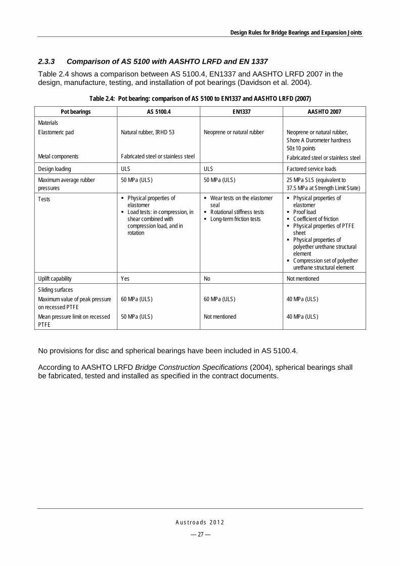
Design Rules for Bridge Bearings and Expansion Joints
A u s t r o a d s 2 0 1 2
— 27 —
2.3.3 Comparison of AS 5100 with AASHTO LRFD and EN 1337 Table 2.4 shows a comparison between AS 5100.4, EN1337 and AASHTO LRFD 2007 in the design, manufacture, testing, and installation of pot bearings (Davidson et al. 2004).
Table 2.4: Pot bearing: comparison of AS 5100 to EN1337 and AASHTO LRFD (2007)
Pot bearings AS 5100.4 EN1337 AASHTO 2007
Materials Elastomeric pad Metal components
Natural rubber, IRHD 53 Fabricated steel or stainless steel
Neoprene or natural rubber
Neoprene or natural rubber, Shore A Durometer hardness 50±10 points Fabricated steel or stainless steel
Design loading ULS ULS Factored service loads
Maximum average rubber pressures
50 MPa (ULS) 50 MPa (ULS) 25 MPa SLS (equivalent to 37.5 MPa at Strength Limit State)
Tests Physical properties of elastomer
Load tests: in compression, in shear combined with compression load, and in rotation
Wear tests on the elastomer seal
Rotational stiffness tests Long-term friction tests
Physical properties of elastomer
Proof load Coefficient of friction Physical properties of PTFE
sheet Physical properties of
polyether urethane structural element
Compression set of polyether urethane structural element
Uplift capability Yes No Not mentioned
Sliding surfaces Maximum value of peak pressure on recessed PTFE Mean pressure limit on recessed PTFE
60 MPa (ULS) 50 MPa (ULS)
60 MPa (ULS) Not mentioned
40 MPa (ULS) 40 MPa (ULS)
No provisions for disc and spherical bearings have been included in AS 5100.4.
According to AASHTO LRFD Bridge Construction Specifications (2004), spherical bearings shall be fabricated, tested and installed as specified in the contract documents.

Design Rules for Bridge Bearings and Expansion Joints
A u s t r o a d s 2 0 1 2
— 28 —
3 AUSTRALIAN MANUFACTURERS OF BRIDGE BEARINGS
3.1 Granor Rubber and Engineering Pty. Ltd 3.1.1 Types of Bearings Manufactured Granor Rubber and Engineering manufactures a range of different structural bearings. The bearings listed on its website include those described below.
Plain pad/strip
Granor plain pad/strip is manufactured in standard maximum length of 1830 mm. The thickness varies from 3 to 25 mm, and the width of the cross-section ranges from 50 to 300 mm. This bearing type can sustain working load range of 250 to 1300 kN/m and can accommodate shear deformations of 1.5 to 13 mm with rotation capacity of 0.003 to 0.06 radians. Complying with RMS-NSW Specification B280 (RTA 2006a) and Austroads Bridge Design Code (Austroads 1992), these bearings also meet all requirements of AS 5100.4.
Pot bearings
Granor provides three types of pot bearings: fixed, free float and guide/slide bearings with respective brand names of potstay, potfloat and potglide (Figure 3.1).
Source: Granor website.
Figure 3.1: Granor pot bearing
Designed for AS 5100.4, the bearings are classified by rated vertical load at the SLS, type of bearing, ratio of horizontal and vertical loads, design transverse movement and design transverse longitudinal movement. In particular, the bearings can be suitable for rated vertical loads at SLS in the range of 300 to 10 000 kN, and horizontal loads at SLS in the range of 45 to 1500 kN for fixed bearings and 30 to 1000 kN for guide/slide and free float bearings.

Design Rules for Bridge Bearings and Expansion Joints
A u s t r o a d s 2 0 1 2
— 29 —
The bearings can accommodate rotations of 0.015 or 0.02 rads, transverse movements of 15 mm for free float bearings, and longitudinal movements of 50 mm for guide/slide and free float bearings.
Laminated elastomeric bearings
Granor elastomeric laminated bearings (Figure 3.2) are manufactured and tested to the requirements of AS 1523 or to Austroads Bridge Design Code 1992 (Granor website). Twenty standard types as specified in AS 5100.4 are available, however with some different capacity, for example, vertical rated load, and calculated compressive stiffness at zero shear (generally lower).
Source: Granor website.
Figure 3.2: Granor laminated elastomeric bearing
Disktron bearing
Granor also manufactures RJ Watson’s disc bearings under license. They come in three types, being fixed, uni-directional, and multi-directional bearings (Figure 3.3).
This type of bearing has a very compact design and can accommodate design loads up to 44 500 kN. High rotation capacity exceeding 0.08 rads, uplift, flexible guided and sliding isolation capacities for bearings in seismic areas are additional features. In addition, this bearing type can be used for all ratios of live to dead load, and the minimum horizontal load capacity is 10% of the vertical load (Granor website).

Design Rules for Bridge Bearings and Expansion Joints
A u s t r o a d s 2 0 1 2
— 30 —
Source: Granor website.
Figure 3.3: Disktron bearings imported by Granor
3.1.2 Manufacturer Recommendations The following recommendations are derived from Granor’s product brochures:
Plain strip/pads
A support area greater than the nominal plan size of the bearing is recommended as the unreinforced plain pad/strip will spread or squirm when loaded. Usually a minimum value of 25 mm will be spared on all edges of the pad/strips.
If a mortar pad is used then a minimum thickness of 10 mm shall be used together with 45o chamfer on the mortar pad sides. If the thickness of the mortar pad is greater than 25 mm then reinforcement may be recommended.
Surfaces should be flat, free of cavities or projections and rough in texture. Use of adhesive is not recommended.
Sheathing the bearing with a suitable fire resistant material or insulating material is recommended if fire resistance is required. Alternatively, minimisation of any settlement if the bearing was destroyed by fire should be taken into consideration.
Elastomeric laminated bearings
Flatness of the contact surface should be within ± 1 mm over the required area to reduce the out-of-parallelism that affects the rotational capacity of the bearing.
The texture of the contact surface should be of a high coefficient of friction. Hot dip galvanised steel surfaces are satisfactory.
Edge clearance should be 25 mm around the bearing.
Mortar pads under the bearing should be 25 to 30 mm and of high quality grout or epoxy.
In an email from Oscar Velo (Granor) on 13 December 2010, further comments on current practice and future directions from a local manufacturer’s point of view were provided as set out below.
Fixed bearing Uni-directional bearing Multi-directional bearing

Design Rules for Bridge Bearings and Expansion Joints
A u s t r o a d s 2 0 1 2
— 31 —
Bearing failures
Plain elastomeric bearing pads and strips
These bearings have minimum application problems. Manufacture faults are very uncommon and would only manifest if improper compounds were used resulting in inferior ozone resistance, and early age hardening. ‘Walk out’ failure may occur because the pads design load bearing capacity is incorrectly calculated or when the slippage criterion of the pads is incorrectly addressed.
Laminated elastomeric bearings
In-service failure of this type of bearing is uncommon and usually relates to similar issues such as incorrect compound formulation, poor manufacture controls on metal to rubber vulcanisation outcomes, causing delaminating and separation of the internal rubber from the internal steel shim plates.
Insufficient allowance for construction rotation arising from beam hog and camber issues may cause ‘lift off’ from the bearing at one or more corners.
Recent trends in engaging in overseas manufacture of these bearings have led to some documented suspect and faulty bearing supplies arising from production issues relating to poor internal alignment of steel plate layers which manifests as visually poor non-uniform bulges and ribs of rubber surface around the perimeter of the bearings.
Structural pot type bearings
Extruding of the confined rubber bearing pads is identified as the most common failure mode or in-service problem with pot bearings.
Premature wearing of the PTFE at the PTFE and stainless steel slide interface can also be a common failure or in-service maintenance problem.
Poor installation techniques have also contributed significantly to in-service failures and reduced longevity of the component. However, installation rules and methodology advice is lacking in current AS 5100 and SRA specifications.
Design standards for bridge bearings
AS 5100.4 is not intended as a detailed design document, which is in contrast with the current European standard EN 1337. Future revision of AS 5100.4 should take this direction into consideration.
Inclusion of alternative low friction materials in lieu of the nominated PTFE at the slide interface in order to address wear outcomes and longevity of the low friction component on pot slide bearings.
Consideration to eliminating the current requirement to carry out co-efficient of friction testing on production batch slide bearings and rather replacing this with a one off establishment test submittal by all manufacturers on co-efficient of friction outcomes for their PTFE alternative material of choice.
Develop a section/clause to address other concepts of structural mechanical bearings, such as ‘disc’ bearings and ‘spherical’ bearings.
Design Rules for Bridge Bearings and Expansion Joints
A u s t r o a d s 2 0 1 2
— 32 —
Current favourable trends and future directions
The procurement of overseas manufactured products has resulted in the fact that the manufacture and testing are not under direct control of the Australian Road Authorities. That fact may lead to product flaws. Thus, meaningful and qualified inspection control needs to be maintained.
SRAs need to be more vigilant and pro-active in monitoring the quality outcomes of overseas products. Specialist training is recommended for personnel both at the testing venue and in inspection of bearings already installed in-situ. Current registration complying with NATA registration does not address this as the approving personnel do not have the required expertise.
There have been recent efforts to familiarise the Australian market with modern generation disc bearings and spherical bearings incorporating the use of PTFE substitute high wear polymers material. Road Authorities need to be receptive to proposals for alternative bearing concepts to the pot bearings and also be receptive to the use of the high wear polymers.
The further development of an ‘approved component’ list for bearings either by individual SRA or indeed by Austroads is recommended with suitable manageable controls and processes.
Any increase in the capacity and the will of SRAs to monitor product quality and to develop more accurate prescriptive specifications for bearings is desired.
3.2 Ludowici 3.2.1 Types of Bearings Manufactured Ludowici’s website indicates that it manufactures the two most popular bearing types in Australia, being laminated elastomeric and pot bearings.
Technical notes by Davison et al. (2004) issued after the release of AS 5100.4 addressed changes in AS 5100.4 compared to the obsolete Austroads Bridge Design Code (1992) and AS 1523 (Elastomeric Bearings for Use in Structures).
Laminated elastomeric bearings
Ludowici provides tables of properties listing the main criteria of different types of bearing for all 20 standard sizes specified in AS 5100.4 and a number of interpolated sizes. Graphs, notes and examples are also provided for design engineers to easily select a suitable bearing size based on structural analysis data and cost consideration. Customised design may also be provided. This bearing is designed for SLS loads and meets all requirements of AS 5100.4.
Pot bearings
This bearing type is available in three categories with the brand names Fixed SD Series, Guided SD Series & Multi-Directional SD Series. Series A and Series B denotes bearing types with high and medium shear capacities, respectively. This bearing is designed for ULS loadings and meets the latest Australian and international standards (AS 5100.4 and EN 1337).

Design Rules for Bridge Bearings and Expansion Joints
A u s t r o a d s 2 0 1 2
— 33 —
Fixed SD series Guided SD series Multi-directional SD
Source: Ludowici website.
Figure 3.4: Ludowici pot bearings
Table 3.1 shows the main features of Ludowici pot bearings.
Table 3.1: Main features of Ludowici pot bearings
Technical items Range of application
Rotations 0.025 rads ULS
Movement in principal direction (guided and multi-directional bearings) ± 50 mm
Movement in transverse direction (guided and multi-directional bearings)
± 20 mm
Compression loads 400 kN to 25 000 kN ULS
Shear loads for small bearings 20% to 30% Nmax
Shear loads for large bearings 5% to 10% Nmax
3.2.2 Manufacturer Recommendations Davison et al. (2004) made recommendations for items such as test frequency, friction test, and testing requirements in the case of uplift bearing, and the introduction of hold points. Most of these recommendations can be seen in recent SRA specifications.

Design Rules for Bridge Bearings and Expansion Joints
A u s t r o a d s 2 0 1 2
— 34 —
In an email on 16 February 2011, Graham Davidson recommended that the current Australian bridge design standard (AS 5100) should provide additional requirements for the design of pot bearings as follows:
Pressure at the bearing and mortar interface should be specified, (and clarified to be at that interface) based on a 60 degree distribution circle from the edge of the potpad, or the PTFE as applicable. This determines the thickness of plates within the bearing and any attachment or distribution plates which distribute the load – which otherwise can be ’designed down to a price’.
PTFE should be etched and bonded into recesses. This is a significant cost, but is justified, because PTFE that becomes displaced from its recess is crushed and starts to extrude.
Stainless steel should not only be 316/2B, but should be machine polished to a mirror finish (#8 polish). This does not affect the initial friction significantly, but there is research which found that it gives better long-term wear and less long-term friction.
3.3 Trelleborg 3.3.1 Types of Bearings Manufactured Elastomeric bearing pad/strip
Trelleborg elastomeric bearing pads and strips (Figure 3.5) are designed and manufactured in accordance with AS 5100.4 and RMS NSW B280 specifications.
The available thickness varies from 5 to 25 mm, and the width of the cross-section ranges from 50 to 250 mm. Other sizes are supplied upon request. This bearing type can sustain a working load range of 200 to 1000 kN/m and can accommodate shear deformations of 2 to 13 mm with rotation capacity of 0.002 to 0.058 radians.
Source: Trelleborg website.
Figure 3.5: Trelleborg bearing pad/strip
Pot bearings
Trelleborg pot bearings (Figure 3.6) are available in three types, being fixed (TF), guided (TGe) and free (TGa). They can be designed and manufactured in accordance to AS 5100.4, AASHTO LRFD or BS 5400 (Trelleborg website).
This type of bearing can sustain large vertical load up to 40 000 kN. Information on rotational and movement capacity is not available on the website.

Design Rules for Bridge Bearings and Expansion Joints
A u s t r o a d s 2 0 1 2
— 35 —
Source: Trelleborg website.
Figure 3.6: A general mobile pot bearing
Rubber laminated bearings
Trelleborg laminated bearings (Figure 3.7) are designed and manufactured in accordance to AS 5100.4. All standard sizes specified in the standard are available.
Source: Trelleborg website.
Figure 3.7: Trelleborg laminated elastomeric bearing
Spherical bearings
Trelleborg also acts as an agent for Maurer Sohne spherical bearings (Figure 3.8). MSM slide and spherical bearings provide large loading capacity (up to 45 000 kN).
Trelleborg also has a base isolation bearing-seismic bearing available. The base isolation bearing-seismic bearing provides self-centering devices that allow displacement between a structure it supports, allowing dissipation of energy to reduce structural damage due to earthquake movement.

Design Rules for Bridge Bearings and Expansion Joints
A u s t r o a d s 2 0 1 2
— 36 —
Source: Trelleborg website.
Figure 3.8: Maurer Sohne spherical bearing
3.3.2 Manufacturer Recommendations In an email from a Xavier Delatte (Trelleborg) on 9 December 2010, the following points were noted:
Disc bearings and spherical bearings are both good. However while spherical bearings are manufactured by many companies, disc bearings are supplied only by RJ Watson and therefore limit competition and choice of designs.
For metal parts, hot dip galvanisation should be used instead of epoxy coatings. This is especially true of pot bearings, where galvanising has been found to be far more durable. The only exception is in rare marine locations where some fungus has been found to attack zinc.
Attachment bolts should be of grade 8.8.
Witness points in testing of elastomeric bearings should be removed to save time and resources.
The future generic specifications should not be limited to any overseas specifications but should be able to cover other systems approved by legitimate and internationally recognised standards or approving authorities.
There should be clear procedures and criteria for the approval of a new product.

Design Rules for Bridge Bearings and Expansion Joints
A u s t r o a d s 2 0 1 2
— 37 —
4 STATE ROAD AUTHORITY EXPERIENCES WITH BRIDGE BEARINGS
4.1 Popular Types of Bridge Bearings Used Nationwide In Australia there are a number of commonly used bearing types. These include:
elastomeric bearings
pot bearings
mechanical bearings
spherical bearings.
4.1.1 Elastomeric Bearings The most common types of bridge bearing used in all states are elastomeric bearings (single layer plain pads, strips and laminated bearings), as observed in most of the SRA specifications and practice. These types are preferable because of their advantageous features (such as low cost and ease of maintenance) and suitability for small-to-medium concrete or steel composite bridges, which are the most popular types of bridge in Australia.
Plain pads and strips (Figure 4.1) are used in small span bridges (7.5-15 m span). Pads are used in girder bridges while strips are used in prestressed concrete planks. The dimensions vary from 50-250 mm in width and 5-25 mm in thickness. The length can be selected based on actual needs. These bearings may accommodate maximum vertical force to 1000 kN/m, translation to 15 mm and rotation to 0.05 rad. Dowels are often used to make fixed bearings.
Source: VicRoads (2007).
Figure 4.1: Elastomeric pad bearing
Laminated elastomeric bearings (Figure 4.2 and Figure 4.3) are used for larger span (7.5-40 m) prestressed concrete planks, concrete I girder, super T or steel girder bridges. Designers may select a suitable bearing from a list of standard bearings in Appendix A of AS 5100.4. There are rectangular and circular shapes. For rectangular bearings, the plan dimensions vary in width (230-600 mm), length (170-600 mm), and thickness (35-293 mm). For circular bearings, the

Design Rules for Bridge Bearings and Expansion Joints
A u s t r o a d s 2 0 1 2
— 38 —
diameter varies in the range of 240-880 mm and the thickness 35-309 mm. The rectangular bearings may sustain a vertical load ranging from 145 kN to 5046 kN and may accommodate a translation in the range 10-114 mm. The relative values for circular bearings are 196-8713 kN and 10-124.5 mm, respectively. If required, movement may be restrained by external devices (Figure 4.4).
Circular bearings are often used in large bridges and skewed or curved bridges where the direction of thermal movements may not be well defined. Rectangular bearings are used for straight bridges where the direction of thermal movements can be transverse or along the beam axis. In these cases, rectangular bearings are used to reduce the bearing size while still ensuring the required shear capacity.
Source: VicRoads (2007).
Figure 4.2: Laminated elastomeric bearing
Figure 4.3: A laminated elastomeric bearing used in Queensland
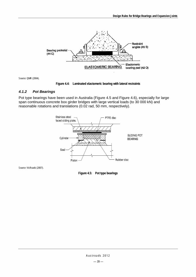
Design Rules for Bridge Bearings and Expansion Joints
A u s t r o a d s 2 0 1 2
— 39 —
Source: QMR (2004).
Figure 4.4: Laminated elastomeric bearing with lateral restraints
4.1.2 Pot Bearings Pot type bearings have been used in Australia (Figure 4.5 and Figure 4.6), especially for large span continuous concrete box girder bridges with large vertical loads (to 30 000 kN) and reasonable rotations and translations (0.02 rad, 50 mm, respectively).
Source: VicRoads (2007).
Figure 4.5: Pot type bearings
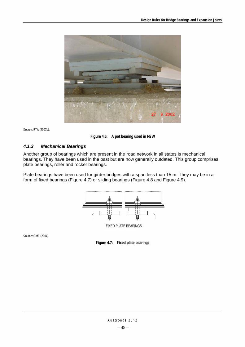
Design Rules for Bridge Bearings and Expansion Joints
A u s t r o a d s 2 0 1 2
— 40 —
Source: RTA (2007b).
Figure 4.6: A pot bearing used in NSW
4.1.3 Mechanical Bearings Another group of bearings which are present in the road network in all states is mechanical bearings. They have been used in the past but are now generally outdated. This group comprises plate bearings, roller and rocker bearings.
Plate bearings have been used for girder bridges with a span less than 15 m. They may be in a form of fixed bearings (Figure 4.7) or sliding bearings (Figure 4.8 and Figure 4.9).
Source: QMR (2004).
Figure 4.7: Fixed plate bearings
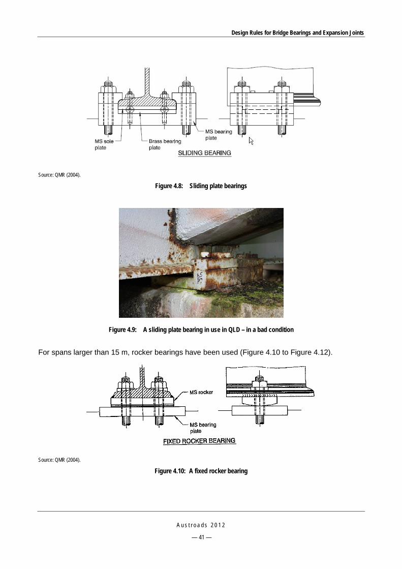
Design Rules for Bridge Bearings and Expansion Joints
A u s t r o a d s 2 0 1 2
— 41 —
Source: QMR (2004).
Figure 4.8: Sliding plate bearings
Figure 4.9: A sliding plate bearing in use in QLD – in a bad condition
For spans larger than 15 m, rocker bearings have been used (Figure 4.10 to Figure 4.12).
Source: QMR (2004).
Figure 4.10: A fixed rocker bearing
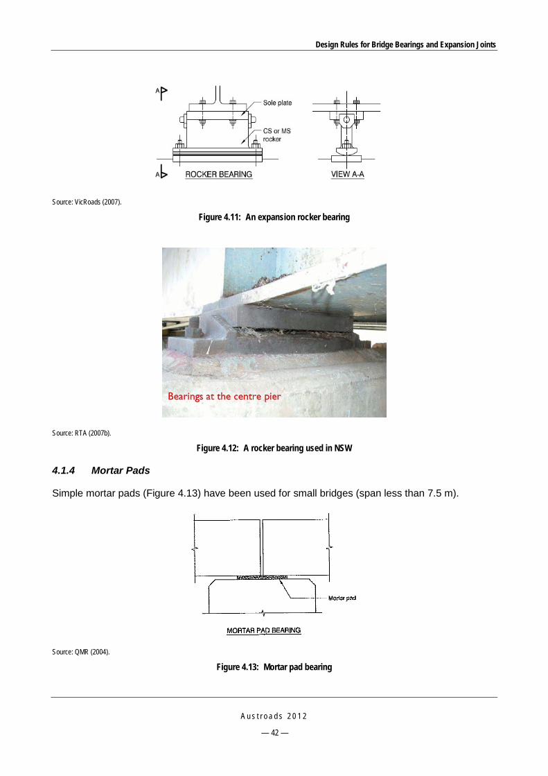
Design Rules for Bridge Bearings and Expansion Joints
A u s t r o a d s 2 0 1 2
— 42 —
Source: VicRoads (2007).
Figure 4.11: An expansion rocker bearing
Source: RTA (2007b).
Figure 4.12: A rocker bearing used in NSW
4.1.4 Mortar Pads
Simple mortar pads (Figure 4.13) have been used for small bridges (span less than 7.5 m).
Source: QMR (2004).
Figure 4.13: Mortar pad bearing

Design Rules for Bridge Bearings and Expansion Joints
A u s t r o a d s 2 0 1 2
— 43 —
4.2 Roads and Maritime Services, New South Wales (RMS) 4.2.1 Specifications Currently RMS uses the following quality assurance specifications for design, manufacture, supply, and installation of bearings (Table 4.1):
Table 4.1: Specifications for bearings in RMS
Code Name Date of issue
B280 Unreinforced elastomeric bearing pads and strips 2006
B281 Laminated elastomeric bearings 2006
B282 Pot bearings – structural steel 2007
B283 Pot bearings – stainless steel 2005
B284 Installation of bridge bearings 2008 B280 and B281 set out the requirements for the supply of unreinforced elastomeric bearing pads and strips, and laminated elastomeric bearings, respectively. Generally they conform to AS 5100.4, except specifying some requirements in more detail. For elastomeric pads and strips, the main differences between B280 and AS 5100.4 are outlined in Table 4.2.
Table 4.2: Differences between RMS specification for elastomeric pads and strips and AS 5100.4
Item AS 5100.4 B280
Tolerances in plan dimension +4/-2 mm ±2 mm
Tolerances: thickness ±0.2 mm + 10% the design thickness ±1 mm
Parallelism of top and bottom surfaces 1.5 mm or 0.3% diameter 1 (0.5) mm for pad (strip)
Number of representatives Determined by quality control and previous test data
2 for each 25 pads, 6 per lot of strips
Tolerances on compressive stiffness Not specified ±20% the mean value of test samples
Tolerances on shear stiffness ±20% the design value ±20% the values given in table B280.2 for 2 pad sizes and 4 strip sizes (Pads 350x250x25, 450x250x25; Strips: 400x65x20, 400x125x25, 400x150x25)
Acceptance criteria for pads and strips Not mentioned clearly Rejected if splitting, permanent deformation, significantly irregular or unsymmetrical surface bulging
For laminated elastomeric bearings, RMS specification B281 requires that all bearings shall be tested in compression and shear, and one per 20 identical bearings shall be tested in rotation. In addition, the tolerance in compressive stiffness is required to be 15% of the mean value of all bearings in a batch.

Design Rules for Bridge Bearings and Expansion Joints
A u s t r o a d s 2 0 1 2
— 44 —
B282 specifies the requirements for the design, fabrication, testing, protective treatment, supply and installation of structural steel pot bearings and associated attachment plates. The main differences compared to AS 5100.4 are summarised below:
Materials used for sliding surfaces and guide bars shall conform to ASTM 240M while they shall conform to AS 1449 type 316 2B in AS 5100.4.
The gap between piston and cylinder shall be no less than 0.5 mm while in AS 5100.4, it requires this gap to be no greater than 1.0 mm.
A provision for lubricant used in a pot bearing was added in which B282 specified that a silicone compound conforms with the test method ASTM D217 or ASTM D972.
For an elastomeric disc, the maximum gap between pot and disc in the unloaded condition shall be 0.2% of the diameter of the disc or 0.5 mm while it is not specified in AS 5100.4.
The number of representatives for testing is 1, 2 or 3 for a number of identical bearings of less than or equal to 10, less than or equal to 25, or greater than or equal to 50, respectively. AS 5100.4 does not specify this provision clearly.
A coefficient of friction test was added which depends on the bearing pressure. If the bearing pressure is 5, 15, 20, and greater than 30 MPa, the respective coefficient of friction shall be no greater than 0.04, 0.025, 0.02, and 0.015.
Protective treatment methods and procedures to avoid corrosion of steel parts were added.
B283 is similar to B282 except it is used for stainless steel and the provisions relating to steel parts and protective treatment are modified.
B284 sets out the requirements for the installation of bridge bearings. It addresses provisions for installation materials such as grout and mortar, the installation tolerances and the installation procedure.
In addition to the above mentioned specifications, RMS often uses parts of European Standard EN 1337 for assessment and design of pot or spherical type bearings (email from Mohamed Anzar on 1 April 2010).
4.2.2 Design and Construction There are a number of recommendations made available through recent publications by RMS to improve the performance of bridge bearings. The recommendations were made based on various modes of failures observed in NSW.
RMS internal instruction CBE 97/5 (RTA 1997a) requires the consideration of using more durable materials such as pot type bearings made of stainless steels, where possible, within 1 km of the coast or under an equivalent environment (manufacture cost will be 4-5 times higher than normal steels). This arose from the fact that one of the most common failure modes in mechanic bearings in NSW is corrosion of metal parts. Furthermore, in a recent internal report on the performance assessment of bridge components (Austroads 2001), it was recommended that the manufacture of metal bearings could be improved by increasing the resistance to corrosion by using cast iron or stainless steel and improving the paint protection system.
RMS internal instruction CBE 98/8 (RTA 1997b) enforces the use of replaceable bearings in RMS funded bridges except where unreinforced elastomeric strip bearings are used in conjunction with prestressed concrete plank bridges.

Design Rules for Bridge Bearings and Expansion Joints
A u s t r o a d s 2 0 1 2
— 45 —
Regarding possible construction faults that may cause bearings not to function properly, RMS bridge policy circulars BCP 2005/03 (RTA 2005b) and BCP 2005/04 (RTA 2005c) require the use of attachment plates in pot type bearings and the epoxy mortar pad in elastomeric bearings for pre-tensioned concrete girders, respectively, in order to adjust for the lack of parallelism between the contact interfaces due to longitudinal grade, cross-fall and hog or camber of the superstructure.
In terms of quality RMS also sets out a series of hold points and witness points for quality control.
4.2.3 Testing Table 4.3 shows the failure criteria used by RMS when testing the new bearings for quality control purposes. The predominant failure modes that have been observed in service are also used as the criteria for acceptance or rejection of the bearings.
Table 4.3: Failure criteria for different bearing types
Number Failure criteria during laboratory testing in accordance with RMS specification
Spherical Pot B282, B283 Elastomer B280, B281
1 Splitting or permanent deformation of elastomer Yes Yes Yes
2 Tearing, cracking or permanent deformation of the PTFE sliding surface
Yes Yes Not applicable
3 Cracking or permanent deformation of any metal component of bearing Yes Yes Not applicable
4 Abrasive marks indicating abnormal contact between any metal surfaces
Yes Yes Not applicable
5 Cracks or permanent deformation of the sealing ring Not applicable Yes Not applicable
6 Significantly irregular or unsymmetrical surface bulging Not applicable Not applicable Yes Source: Austroads (2001). For pot bearings, the tests required for each type of bearing are shown in Table 4.4.
Table 4.4: Tests required for different pot bearings
Bearing type Vertical Lateral Friction Rotation
Fixed Yes Yes No Yes
Free sliding Yes No Yes Yes
Guided sliding Yes Yes Yes Yes By comparison, AS 5100.4 does not require friction tests.
4.2.4 Failures According to Austroads (2001), the failure modes outlined in Table 4.5 were observed during inspections in the period from 1995/96 to 1998.
Table 4.5: Common faults in different types of bearings in NSW
Bearing type Common faults
Confined elastomeric (pot type) Leakage of elastomer (less than 5% inspected bearings). Breakdown of protective system.
Spherical steel or aluminium Breakdown of protective system. Missing bolts. Indentation and deformation of metal plates. Failure of sliding interfaces.

Design Rules for Bridge Bearings and Expansion Joints
A u s t r o a d s 2 0 1 2
— 46 —
Bearing type Common faults
Unconfined elastomeric, laminated
Cracks in elastomer. Excessive bulging or splitting under vertical loads. Slippage and irregular contact of bearing surfaces. Changes in rubber properties with aging. Ozone cracking.
Fabricated steel including roller and rocker
Main problem has been corrosion of the steel, particularly at the sliding interfaces leading to a frozen bearing (approximately 50% of the total number of bearing inspected). Roller or rocker bearings fabricated with stainless steel components including bolts are generally free of corrosion.
Low friction PTFE to stainless steel
Warping of stainless steel sheet due to rusting of the metal backing plate. Wear of PTFE layer.
In addition, the modes of failure of common types of bearing in NSW listed in Table 4.6 were extracted from RMS’s Bridge Inspection Procedure Manual (RTA 2007b).
Table 4.6: Common faults of bearings observed in recent inspections in NSW
Bearing type Common faults
Elastomeric bearings Cracking, splitting or bulging of elastomer; misalignment or lateral movement, excessive shear deformation or loss of bearing function; missing, distorted or corroded dowels; deterioration of materials (Figure 4.14 and Figure 4.15).
Metal bearings Corrosion with pitting; debris and rust build-up stops bearing movements; cracking or spalling in the supporting concrete and loss of support under the bearing; misalignment or excessive movement; failed shear keys (Figure 4.16 and Figure 4.17).
Enclosed/concealed bearings Leakage of rubber; broken seals; excessive vertical and/or horizontal movements; corrosion of ferrous members; cracking or spalling of supporting members (Figure 4.18 and Figure 4.19).
Figure 4.14: Cracking and deterioration of elastomer

Design Rules for Bridge Bearings and Expansion Joints
A u s t r o a d s 2 0 1 2
— 47 —
Figure 4.15: Splitting and bulging of bearing pads
Figure 4.16: Corrosion of a rocker bearing
Figure 4.17: Corrosion and loss of support
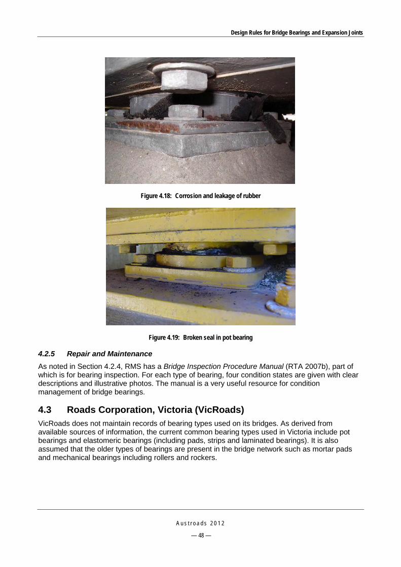
Design Rules for Bridge Bearings and Expansion Joints
A u s t r o a d s 2 0 1 2
— 48 —
Figure 4.18: Corrosion and leakage of rubber
Figure 4.19: Broken seal in pot bearing
4.2.5 Repair and Maintenance As noted in Section 4.2.4, RMS has a Bridge Inspection Procedure Manual (RTA 2007b), part of which is for bearing inspection. For each type of bearing, four condition states are given with clear descriptions and illustrative photos. The manual is a very useful resource for condition management of bridge bearings.
4.3 Roads Corporation, Victoria (VicRoads) VicRoads does not maintain records of bearing types used on its bridges. As derived from available sources of information, the current common bearing types used in Victoria include pot bearings and elastomeric bearings (including pads, strips and laminated bearings). It is also assumed that the older types of bearings are present in the bridge network such as mortar pads and mechanical bearings including rollers and rockers.

Design Rules for Bridge Bearings and Expansion Joints
A u s t r o a d s 2 0 1 2
— 49 —
4.3.1 Specifications There are standard specification sections (materials, testing and installation) regarding supply and installation of bridge bearings which include:
Standard section 652 – Supply of Elastomeric Bearings (VicRoads 2004a).
Standard section 653 – Pot Type Confined Elastomeric Bearings (VicRoads 2004b).
Standard section 656 – Installation of Elastomeric Bearings and Pads (VicRoads 2004c).
No additional specifications are available for plain pads, strips and mechanical bearings.
4.3.2 Design and Construction VicRoads issues various bridge technical notes which specify the requirements for design, testing and construction of bridge bearings. VicRoads (2005a) sets out a design procedure for laminated elastomeric bearings. It generally follows AS 5100.4 with some additional requirements specified in the standard specification sections 652 (VicRoads 2004a) and 656 (VicRoads 2004c). Those additional requirements include:
Number of representatives for compression test: 1 per 10 bearings.
For shear test, all bearings shall be tested if the bearing dimensions are larger than 480 x 250 mm or there are less than 12 bearings in a batch, otherwise 12, 16 or 20 bearings shall be tested if the number of bearings in a batch is 13-30, 31-100 or more than 100, respectively.
The tolerance on compressive stiffness required is to be no greater than 20%.
The design and construction process for bridge bearings is controlled by a checklist (VicRoads 2005b) with a hold point that sets out the criteria to be met upon the acceptance to proceed. However, there is only one hold point for pot bearings.
New products that comply with the design and specification requirements may be considered for use. VicRoads does not maintain lists of approved joints or bearings nor does it currently have an evaluation or approval process. Proposals in relation to products of this type are normally submitted by contractors to the Superintendent who may, in-turn, seek advice about their use from the Structures Section. For wholly new items, this process may include an appraisal of information from the supplier. Once a product has been accepted on this basis, subsequent use on other projects is a simpler process. There is a possibility that an approval process may be implemented in the near future but no specific details of this are available.
Similar to RMS, recommendations are also made regarding the construction faults that might cause poorly functioning bearings. Typically, the use of bi-axial tapered attachment plates, levelling screws or epoxy mortar in pot bearings and elastomeric bearings is encouraged for pre-tensioned concrete girders. These assist by adjusting for the lack of parallelism between the contact interfaces due to longitudinal grade, cross-fall and hog or camber of the superstructure.

Design Rules for Bridge Bearings and Expansion Joints
A u s t r o a d s 2 0 1 2
— 50 —
4.3.3 Testing VicRoads (2005b) provides a checklist for the review of testing carried out on pot bearings in accordance with VicRoads standard section 653 (VicRoads 2004b). This checklist summarises all key criteria in the specification in a tabular form. In general it conforms to AS 5100.4; however, there are some differences as listed below:
The minimum thickness of the elastomeric disc is 1/20 the disc diameter instead of 1/15 or 10 mm as specified in AS 5100.4.
The average compression stress on pure PTFE is required to be no greater than 30 MPa under minimum vertical serviceability load and 45 MPa under maximum vertical ultimate load, while AS 5100.4 specifies that the maximum mean compression stress is 50 MPa.
Similarly, the peak compression stress on pure PTFE is required to be no greater than 35 MPa under minimum vertical serviceability load and 55 MPa under maximum vertical ultimate load, while AS 5100.4 specifies that the maximum peak compression stress is 60 MPa.
For the vertical load test, while AS 5100.4 requires testing with maximum ultimate compressive load, VicRoads standard requires that the load test be 1.5 times the vertical ULS load.
For the shear load test, AS 5100.4 requires testing with two combinations (maximum ultimate lateral load plus minimum ultimate vertical load, and maximum ultimate lateral load plus maximum ultimate vertical load), while the VicRoads standard requires that the load test be 1.5 times the vertical ULS load plus the minimum vertical ULS load.
For the rotation test, AS 5100.4 requires testing under the design rotation at 0.7 time the maximum ultimate vertical load, VicRoads requires that the rotation test be carried out at a design rotation with maximum vertical ULS load and if applicable lateral SLS load.
In addition to the standard tests specified in AS 5100.4 which are revised in VicRoads specifications, the following criteria shall be used to reject the faulty bearings:
extrusion of the elastomer from the pot
tearing, cracking or permanent deformation of the PTFE sliding surface
cracking or permanent deformation of the sealing ring or other part of the bearing
abrasive marks indicating abnormal contact between the metal surfaces of the bearing plates or piston, and the pot.
4.3.4 Failures The following possible failures (Table 4.7) are extracted from VicRoads Bridge Inspection Manual (VicRoads 2007) and the database provided by VicRoads’ Network and Asset Planning (email from Mahes T Maheswaran on 21 February 2011).
Table 4.7: Common failure modes of bearings in Victoria
Bearing type Common faults
Component 40O: Fixed bearings (steel plate bearing on concrete, concrete bearing on malthoid, lead sheet)
Spalling of the ends of the beams; corrosion of steel plates; deterioration or extrusion of malthoid or lead sheet; cracking or spalling of support member.
Component 41O: Sliding bearings Corrosion of steel plates; sliding elements slipped out or not functioned properly; PTFE delaminated, buckled or destroyed; cracking or crushing of support concrete members.

Design Rules for Bridge Bearings and Expansion Joints
A u s t r o a d s 2 0 1 2
— 51 —
Bearing type Common faults
Component 42O: Elastomeric/pot bearings Bulging, cracking, splitting or delamination of elastomer; excessive shear or rotation deformations; extrusion of elastomer through cracks on pot container.
Component 43S: Rockers/rollers Corrosion of steel members; bearing seized due to excessive debris or failed lubrication system; excessive rotation of rockers; cracking or spalling of supporting members.
Component 44C: Mortar pads/high bearing pedestals
Crushing or loss of mortar in bearing area; cracking or spalling on high concrete pedestals.
4.3.5 Repair and Maintenance VicRoads Bridge Inspection Manual (VicRoads 2007) lists possible condition states for five types of common bearings used in Victoria: fixed bearings 40O, sliding bearing 41O, elastomeric/pot bearings 42O, rockers/rollers 43S, and mortar pads/high bearing pedestals 44C.
4.4 Department of Transport and Main Roads, Queensland (TMR) 4.4.1 Specifications Specifications and technical standards for bridge bearings issued by TMR include:
MRTS 81 – Bridge Bearings (TMR 2009a)
MRTS 81a – Stainless Bridge Bearings (TMR 2009b)
MRS 81 Main Roads Standard Specification – Bridge Bearings (TMR 2010).
These specifications and standards are very much similar to RMS’s equivalent specifications except for some minor modifications.
For elastomeric pads and strips, the followings are specified differently from AS 5100.4:
Tolerance on plan dimensions is ±3 mm, while it is +4/-2 mm in AS 5100.4.
Tolerance in thickness is ±2 mm, while it is ±0.2 mm plus 10% the design thickness in AS 5100.4.
Parallelism of top and bottom surfaces is 1 mm, while it is 1.5 mm or 0.3% diameter in AS 5100.4.
Number of test representatives is 1 per 10 bearings in a batch, while AS 5100.4 does not specify.
Test load is 3 times the working load while it is 1.5 times the rated SLS load in AS 5100.4.
For laminated elastomeric bearings, it is similar to AS 5100.4 except the number of test representative is 1 per 5 bearings and the tolerance on compressive stiffness is ±25% of the design value.
There are also criteria for acceptance of elastomeric bearings based on visual checks during testing.
For pot bearings, most of the provisions in MRTS 81 and MRTS81a are similar to those of RMS’s B282 and B283, respectively, except the introduction of ASTM D4745 and ASTM D3294 for material and testing of sliding surfaces.
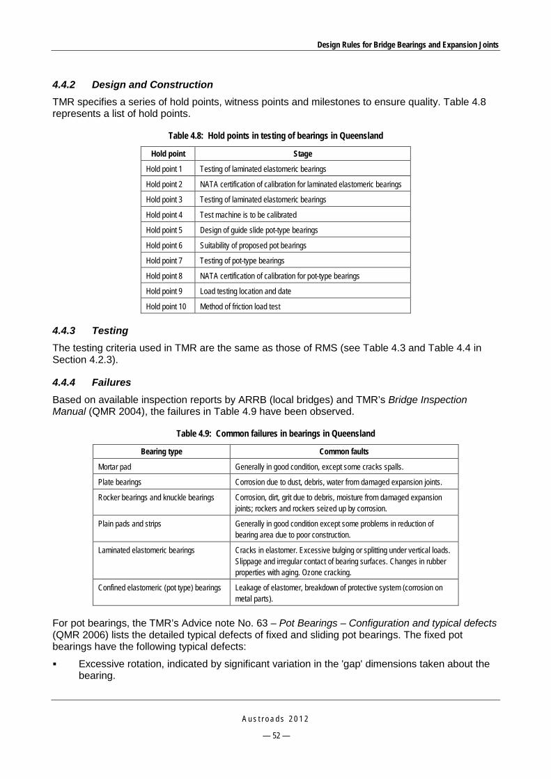
Design Rules for Bridge Bearings and Expansion Joints
A u s t r o a d s 2 0 1 2
— 52 —
4.4.2 Design and Construction TMR specifies a series of hold points, witness points and milestones to ensure quality. Table 4.8 represents a list of hold points.
Table 4.8: Hold points in testing of bearings in Queensland
Hold point Stage
Hold point 1 Testing of laminated elastomeric bearings
Hold point 2 NATA certification of calibration for laminated elastomeric bearings
Hold point 3 Testing of laminated elastomeric bearings
Hold point 4 Test machine is to be calibrated
Hold point 5 Design of guide slide pot-type bearings
Hold point 6 Suitability of proposed pot bearings
Hold point 7 Testing of pot-type bearings
Hold point 8 NATA certification of calibration for pot-type bearings
Hold point 9 Load testing location and date
Hold point 10 Method of friction load test
4.4.3 Testing The testing criteria used in TMR are the same as those of RMS (see Table 4.3 and Table 4.4 in Section 4.2.3).
4.4.4 Failures Based on available inspection reports by ARRB (local bridges) and TMR’s Bridge Inspection Manual (QMR 2004), the failures in Table 4.9 have been observed.
Table 4.9: Common failures in bearings in Queensland
Bearing type Common faults
Mortar pad Generally in good condition, except some cracks spalls.
Plate bearings Corrosion due to dust, debris, water from damaged expansion joints.
Rocker bearings and knuckle bearings Corrosion, dirt, grit due to debris, moisture from damaged expansion joints; rockers and rockers seized up by corrosion.
Plain pads and strips Generally in good condition except some problems in reduction of bearing area due to poor construction.
Laminated elastomeric bearings Cracks in elastomer. Excessive bulging or splitting under vertical loads. Slippage and irregular contact of bearing surfaces. Changes in rubber properties with aging. Ozone cracking.
Confined elastomeric (pot type) bearings Leakage of elastomer, breakdown of protective system (corrosion on metal parts).
For pot bearings, the TMR’s Advice note No. 63 – Pot Bearings – Configuration and typical defects (QMR 2006) lists the detailed typical defects of fixed and sliding pot bearings. The fixed pot bearings have the following typical defects:
Excessive rotation, indicated by significant variation in the 'gap' dimensions taken about the bearing.

Design Rules for Bridge Bearings and Expansion Joints
A u s t r o a d s 2 0 1 2
— 53 —
Uplift/separation of the piston and cylinder, indicated by an increase in the gap dimension and/or exposure of the elastomer/rubber material.
Heavily spalled or crushed concrete at the bearing support.
Cracking of the steel cylinder, with subsequent extrusion of the elastomer/rubber through the cracks.
Internal deterioration of the elastomer/rubber, with subsequent discharge of the disc material through the gap between the piston and the cylinder.
Similarly, the following typical defects may occur in sliding pot bearings:
Excessive rotation, indicated by significant variations in the gap dimensions taken between the cylinder and piston.
Excessive displacement of stainless steel-faced sliding plate. Where side stops are not installed, this displacement should be measured in both the longitudinal and transverse directions.
Uplift/separation of the PTFE sheet and stainless steel sliding surface, indicated by an increase in the upper gap dimension. Inspectors should confirm that this is the case by inserting a thin strip of material (i.e. a folded piece of paper) into the gap to determine the degree of separation. If the material is making contact at a uniform distance (normally 40-60 mm) around the bearing, then the sliding surface is seated on the PTFE. If there is no contact, then assume the sliding surface has lifted off the PTFE sheet.
Squashing/delamination/deformation of the PTFE sheet, normally indicated by part or all of the sheet being pushed or extruded out of the gap.
Heavily spalled or crushed concrete at the bearing support.
Cracking of the steel cylinder, with subsequent extrusion of the elastomer/rubber through the cracks.
4.4.5 Repair and Maintenance TMR has its own inspection manual which clearly lists out four condition states for each type of common bearing used in Queensland. This part of TMR’s Bridge Inspection Manual is identical to the VicRoads manual.
4.5 Main Roads Western Australia (MRWA) 4.5.1 Specifications Specification 860 Bridge Bearings (MRWA 2010), which was issued in June 2010, sets out the requirements for design, manufacture and installation of elastomeric and pot bearings. This specification is largely in line with AS 5100.4 and manufacturers’ recommendations. The only significant differences include additional tests (stability and proof tests) and the requirements of the coefficients of friction for unlubricated sliding surfaces (the values are twice as much as those specified in RMS or TMR specifications – Table 4.10). It is worth noting that AS 5100.4 does not specify a test for coefficient of friction.

Design Rules for Bridge Bearings and Expansion Joints
A u s t r o a d s 2 0 1 2
— 54 —
Table 4.10: Friction coefficient of sliding surfaces – MRWA
Bearing pressure 5 MPa 10 MPa 15 MPa 20 MPa 30 MPa or greater Friction coefficient 0.08 0.06 0.05 0.04 0.03
4.5.2 Design and Construction MRWA uses predominately elastomeric and pot bearings. There are a number of other bearing types but these are more seldom used in design.
MRWA extended the design requirements specified in AS 5100.4 for one more case where it allows an overstress allowance of 25% under ULS when sustaining high load platform (HLP) or special vehicle loads as the failure can result in large transverse displacements (MRWA 2008).
4.5.3 Testing MRWA has always required fairly high levels of testing including tests in addition to those in AS 5100.4 for acceptance of elastomeric bearings and this has contributed to their successful use. In addition to standard tests specified in AS 5100.4, the following additional tests are required:
Stability test: 50% of bearings tested to check the lateral deflection. The bearing shall be rejected if the lateral deflection under test load is greater than 5% of the vertical height of the bearing.
Proof loading: one pair of bearings per each type shall be tested in three test load combination: (i) The rated load at zero rotation and maximum shear plus 1.5 times the maximum rated shear deflection; (ii) 1.5 times the rated load at zero rotation and maximum shear plus the maximum rated shear deflection; and (iii) 1.5 times the maximum rated shear deflection plus 0.5 times the rated load at zero rotation and maximum shear.
Determination of bearing stiffness: all bearings shall be tested for compressive stiffness and the tolerance in compressive stiffness is 15% of the mean value; 50% of the bearings of each type, with a minimum of two bearings, shall be tested for shear and the tolerance in shear stiffness is 20% of the value given in AS 5100.4.
4.5.4 Failures Elastomeric bearings have generally been found to perform well although they are very dependent on the manufacturer. There was a period some years ago where there was a quality issue with a supplier and some bearings from that era have failed. This was evident in northern areas with high ambient temperatures and some thin bearings yielded (collapsed). Figure 4.19 shows an example of slight bulging of an elastomeric bearing.
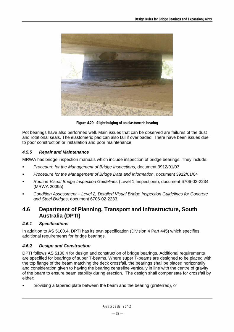
Design Rules for Bridge Bearings and Expansion Joints
A u s t r o a d s 2 0 1 2
— 55 —
Figure 4.20: Slight bulging of an elastomeric bearing
Pot bearings have also performed well. Main issues that can be observed are failures of the dust and rotational seals. The elastomeric pad can also fail if overloaded. There have been issues due to poor construction or installation and poor maintenance.
4.5.5 Repair and Maintenance MRWA has bridge inspection manuals which include inspection of bridge bearings. They include:
Procedure for the Management of Bridge Inspections, document 3912/01/03
Procedure for the Management of Bridge Data and Information, document 3912/01/04
Routine Visual Bridge Inspection Guidelines (Level 1 Inspections), document 6706-02-2234 (MRWA 2009a)
Condition Assessment – Level 2, Detailed Visual Bridge Inspection Guidelines for Concrete and Steel Bridges, document 6706-02-2233.
4.6 Department of Planning, Transport and Infrastructure, South Australia (DPTI)
4.6.1 Specifications In addition to AS 5100.4, DPTI has its own specification (Division 4 Part 445) which specifies additional requirements for bridge bearings.
4.6.2 Design and Construction DPTI follows AS 5100.4 for design and construction of bridge bearings. Additional requirements are specified for bearings of super T-beams. Where super T-beams are designed to be placed with the top flange of the beam matching the deck crossfall, the bearings shall be placed horizontally and consideration given to having the bearing centreline vertically in line with the centre of gravity of the beam to ensure beam stability during erection. The design shall compensate for crossfall by either:
providing a tapered plate between the beam and the bearing (preferred), or
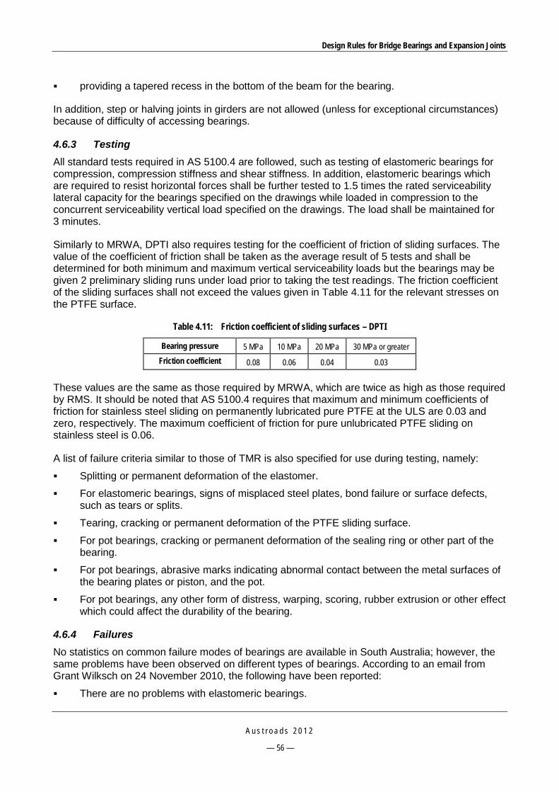
Design Rules for Bridge Bearings and Expansion Joints
A u s t r o a d s 2 0 1 2
— 56 —
providing a tapered recess in the bottom of the beam for the bearing.
In addition, step or halving joints in girders are not allowed (unless for exceptional circumstances) because of difficulty of accessing bearings.
4.6.3 Testing All standard tests required in AS 5100.4 are followed, such as testing of elastomeric bearings for compression, compression stiffness and shear stiffness. In addition, elastomeric bearings which are required to resist horizontal forces shall be further tested to 1.5 times the rated serviceability lateral capacity for the bearings specified on the drawings while loaded in compression to the concurrent serviceability vertical load specified on the drawings. The load shall be maintained for 3 minutes.
Similarly to MRWA, DPTI also requires testing for the coefficient of friction of sliding surfaces. The value of the coefficient of friction shall be taken as the average result of 5 tests and shall be determined for both minimum and maximum vertical serviceability loads but the bearings may be given 2 preliminary sliding runs under load prior to taking the test readings. The friction coefficient of the sliding surfaces shall not exceed the values given in Table 4.11 for the relevant stresses on the PTFE surface.
Table 4.11: Friction coefficient of sliding surfaces – DPTI
Bearing pressure 5 MPa 10 MPa 20 MPa 30 MPa or greater Friction coefficient 0.08 0.06 0.04 0.03
These values are the same as those required by MRWA, which are twice as high as those required by RMS. It should be noted that AS 5100.4 requires that maximum and minimum coefficients of friction for stainless steel sliding on permanently lubricated pure PTFE at the ULS are 0.03 and zero, respectively. The maximum coefficient of friction for pure unlubricated PTFE sliding on stainless steel is 0.06.
A list of failure criteria similar to those of TMR is also specified for use during testing, namely:
Splitting or permanent deformation of the elastomer.
For elastomeric bearings, signs of misplaced steel plates, bond failure or surface defects, such as tears or splits.
Tearing, cracking or permanent deformation of the PTFE sliding surface.
For pot bearings, cracking or permanent deformation of the sealing ring or other part of the bearing.
For pot bearings, abrasive marks indicating abnormal contact between the metal surfaces of the bearing plates or piston, and the pot.
For pot bearings, any other form of distress, warping, scoring, rubber extrusion or other effect which could affect the durability of the bearing.
4.6.4 Failures No statistics on common failure modes of bearings are available in South Australia; however, the same problems have been observed on different types of bearings. According to an email from Grant Wilksch on 24 November 2010, the following have been reported:
There are no problems with elastomeric bearings.
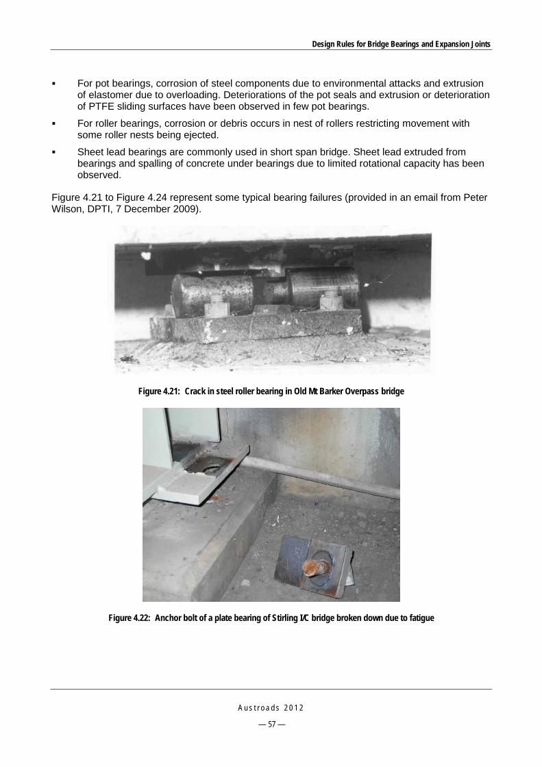
Design Rules for Bridge Bearings and Expansion Joints
A u s t r o a d s 2 0 1 2
— 57 —
For pot bearings, corrosion of steel components due to environmental attacks and extrusion of elastomer due to overloading. Deteriorations of the pot seals and extrusion or deterioration of PTFE sliding surfaces have been observed in few pot bearings.
For roller bearings, corrosion or debris occurs in nest of rollers restricting movement with some roller nests being ejected.
Sheet lead bearings are commonly used in short span bridge. Sheet lead extruded from bearings and spalling of concrete under bearings due to limited rotational capacity has been observed.
Figure 4.21 to Figure 4.24 represent some typical bearing failures (provided in an email from Peter Wilson, DPTI, 7 December 2009).
Figure 4.21: Crack in steel roller bearing in Old Mt Barker Overpass bridge
Figure 4.22: Anchor bolt of a plate bearing of Stirling I/C bridge broken down due to fatigue
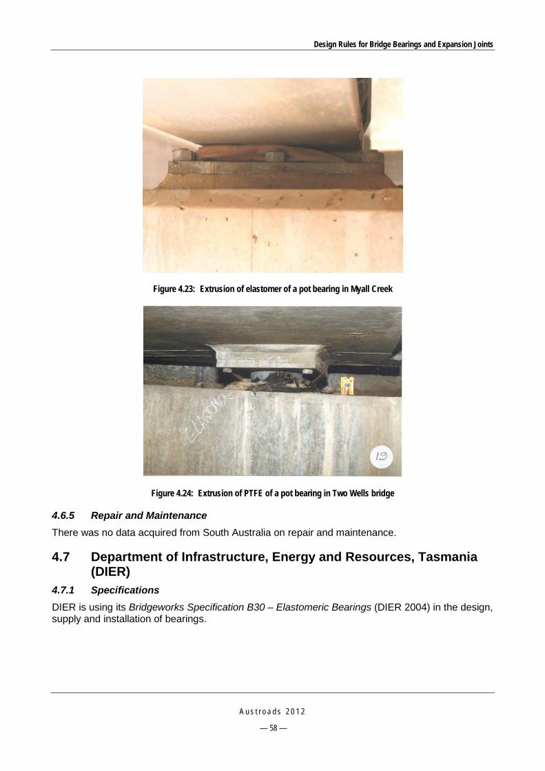
Design Rules for Bridge Bearings and Expansion Joints
A u s t r o a d s 2 0 1 2
— 58 —
Figure 4.23: Extrusion of elastomer of a pot bearing in Myall Creek
Figure 4.24: Extrusion of PTFE of a pot bearing in Two Wells bridge
4.6.5 Repair and Maintenance There was no data acquired from South Australia on repair and maintenance.
4.7 Department of Infrastructure, Energy and Resources, Tasmania (DIER)
4.7.1 Specifications DIER is using its Bridgeworks Specification B30 – Elastomeric Bearings (DIER 2004) in the design, supply and installation of bearings.

Design Rules for Bridge Bearings and Expansion Joints
A u s t r o a d s 2 0 1 2
— 59 —
4.7.2 Design and Construction DIER follows AS 5100.4 in design and construction of bridge bearings with the exception of expansion bearings, in that the PTFE pad shall have a nominal thickness of 4.5 mm. In addition, it requires the use of two plain bearing sizes: 380 x 100 x 20 mm and 600 x 125 x 25 mm.
4.7.3 Testing DIER follows all standard tests required in AS 5100.4; however, there are some additional requirements in testing of elastomeric and pot bearings.
Tolerances on compressive stiffness of laminated bearings are specified differently from other states (Table 4.12).
Table 4.12: Tolerances on compressive stiffness of laminated bearings
Compressive deflection (mm) Layer thickness (mm) Tolerance (%)
< 0.75 6 30
9, 12, 15, 18 25
0.75 to 1.25 6 25
9, 12, 15, 18 20
1.25 to 2.5 6 25
9, 12, 15, 18 25
2.5 to 4.0 6 20
9, 12, 15, 18 15
> 4.0 6 Not applicable
9, 12, 15, 18 15 Allowable shear stiffness for laminated bearings is ± 20%.
A list of failure criteria is also used to visually check the bearings during testing including:
splitting or permanent deformation of the elastomer
tearing, cracking or permanent deformation of the PTFE sliding surface
significantly irregular or unsymmetrical surface bulging
cracking or permanent deformation of the sealing ring or other part of the bearing
abrasive damage indicating abnormal contact between the metal surfaces of the bearing plates or piston, and the pot.
For pot bearings, tests for coefficient of friction are also included for sliding surfaces, which limit the maximum coefficient of friction as shown in Table 4.13.
Table 4.13: Friction coefficient specified by DIER
Bearing pressure 5 MPa 15 MPa 20 MPa Friction coefficient 0.08 0.05 0.04
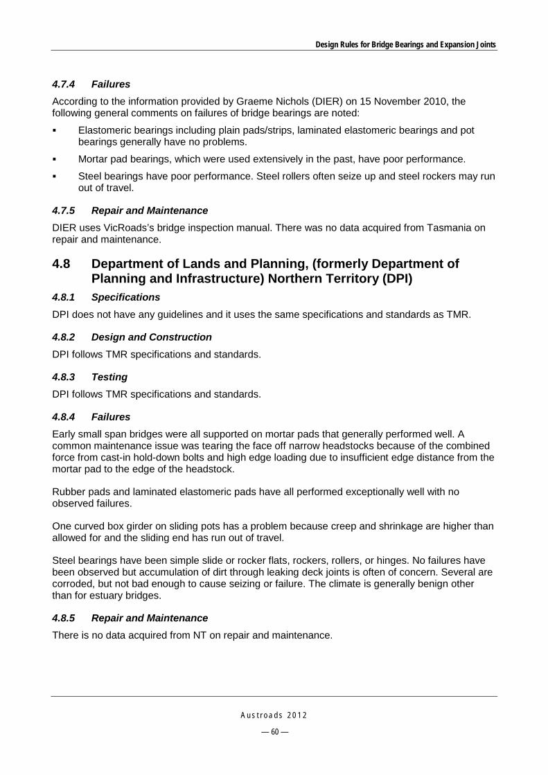
Design Rules for Bridge Bearings and Expansion Joints
A u s t r o a d s 2 0 1 2
— 60 —
4.7.4 Failures According to the information provided by Graeme Nichols (DIER) on 15 November 2010, the following general comments on failures of bridge bearings are noted:
Elastomeric bearings including plain pads/strips, laminated elastomeric bearings and pot bearings generally have no problems.
Mortar pad bearings, which were used extensively in the past, have poor performance.
Steel bearings have poor performance. Steel rollers often seize up and steel rockers may run out of travel.
4.7.5 Repair and Maintenance DIER uses VicRoads’s bridge inspection manual. There was no data acquired from Tasmania on repair and maintenance.
4.8 Department of Lands and Planning, (formerly Department of Planning and Infrastructure) Northern Territory (DPI)
4.8.1 Specifications DPI does not have any guidelines and it uses the same specifications and standards as TMR.
4.8.2 Design and Construction DPI follows TMR specifications and standards.
4.8.3 Testing DPI follows TMR specifications and standards.
4.8.4 Failures Early small span bridges were all supported on mortar pads that generally performed well. A common maintenance issue was tearing the face off narrow headstocks because of the combined force from cast-in hold-down bolts and high edge loading due to insufficient edge distance from the mortar pad to the edge of the headstock.
Rubber pads and laminated elastomeric pads have all performed exceptionally well with no observed failures.
One curved box girder on sliding pots has a problem because creep and shrinkage are higher than allowed for and the sliding end has run out of travel.
Steel bearings have been simple slide or rocker flats, rockers, rollers, or hinges. No failures have been observed but accumulation of dirt through leaking deck joints is often of concern. Several are corroded, but not bad enough to cause seizing or failure. The climate is generally benign other than for estuary bridges.
4.8.5 Repair and Maintenance There is no data acquired from NT on repair and maintenance.

Design Rules for Bridge Bearings and Expansion Joints
A u s t r o a d s 2 0 1 2
— 61 —
4.9 ACT Department of Territory and Municipal Services (ACT TAMS) 4.9.1 Specifications ACT TAMS uses AS 5100.4 and there is no additional specification for bridge bearings.
4.9.2 Design and Construction There are no additional requirements to AS 5100.4.
4.9.3 Testing There are no additional requirements to AS 5100.4.
4.9.4 Failures There exist some reports on bridge inspection and repair works. The same failure modes of different types of bearings as in other states have also been observed.
Possible faults in metal bearings can be seen in the report by Lyons (2009) on Bridge 2097 over the Molonglo River (Figure 4.25 and Figure 4.26). They include:
corrosion of metal plates and anchor bolts
cracks and spalls of supporting concrete pedestals led to reduction of bearing area under the bottom bearing plate.
Figure 4.25: Failure modes of metal bearings in Bridge 2097 in ACT (1)
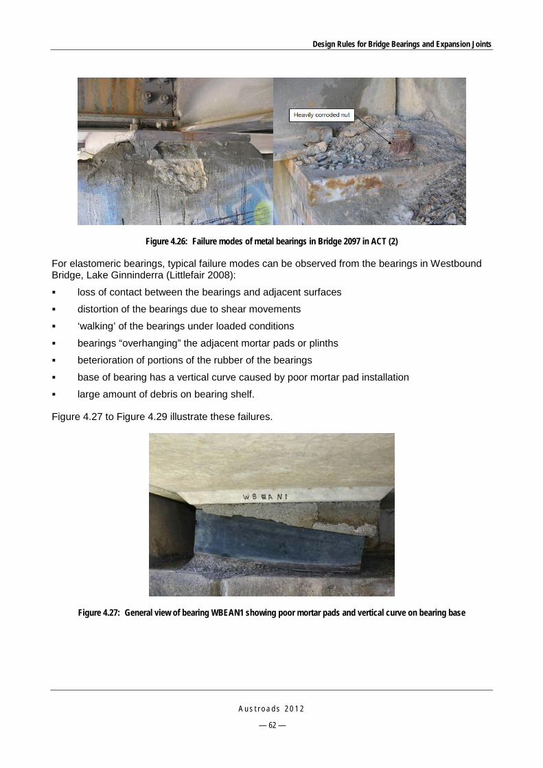
Design Rules for Bridge Bearings and Expansion Joints
A u s t r o a d s 2 0 1 2
— 62 —
Figure 4.26: Failure modes of metal bearings in Bridge 2097 in ACT (2)
For elastomeric bearings, typical failure modes can be observed from the bearings in Westbound Bridge, Lake Ginninderra (Littlefair 2008):
loss of contact between the bearings and adjacent surfaces
distortion of the bearings due to shear movements
‘walking’ of the bearings under loaded conditions
bearings “overhanging” the adjacent mortar pads or plinths
beterioration of portions of the rubber of the bearings
base of bearing has a vertical curve caused by poor mortar pad installation
large amount of debris on bearing shelf.
Figure 4.27 to Figure 4.29 illustrate these failures.
Figure 4.27: General view of bearing WBEAN1 showing poor mortar pads and vertical curve on bearing base
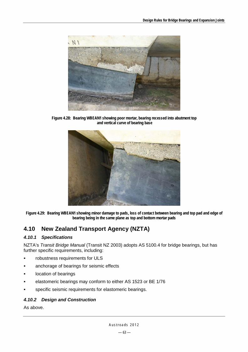
Design Rules for Bridge Bearings and Expansion Joints
A u s t r o a d s 2 0 1 2
— 63 —
Figure 4.28: Bearing WBEAN1 showing poor mortar, bearing recessed into abutment top and vertical curve of bearing base
Figure 4.29: Bearing WBEAN1 showing minor damage to pads, loss of contact between bearing and top pad and edge of bearing being in the same plane as top and bottom mortar pads
4.10 New Zealand Transport Agency (NZTA) 4.10.1 Specifications NZTA’s Transit Bridge Manual (Transit NZ 2003) adopts AS 5100.4 for bridge bearings, but has further specific requirements, including:
robustness requirements for ULS
anchorage of bearings for seismic effects
location of bearings
elastomeric bearings may conform to either AS 1523 or BE 1/76
specific seismic requirements for elastomeric bearings.
4.10.2 Design and Construction As above.
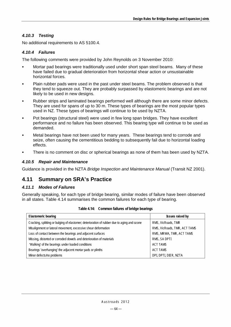
Design Rules for Bridge Bearings and Expansion Joints
A u s t r o a d s 2 0 1 2
— 64 —
4.10.3 Testing No additional requirements to AS 5100.4.
4.10.4 Failures The following comments were provided by John Reynolds on 3 November 2010:
Mortar pad bearings were traditionally used under short span steel beams. Many of these have failed due to gradual deterioration from horizontal shear action or unsustainable horizontal forces.
Plain rubber pads were used in the past under steel beams. The problem observed is that they tend to squeeze out. They are probably surpassed by elastomeric bearings and are not likely to be used in new designs.
Rubber strips and laminated bearings performed well although there are some minor defects. They are used for spans of up to 30 m. These types of bearings are the most popular types used in NZ. These types of bearings will continue to be used by NZTA.
Pot bearings (structural steel) were used in few long span bridges. They have excellent performance and no failure has been observed. This bearing type will continue to be used as demanded.
Metal bearings have not been used for many years. These bearings tend to corrode and seize, often causing the cementitious bedding to subsequently fail due to horizontal loading effects.
There is no comment on disc or spherical bearings as none of them has been used by NZTA.
4.10.5 Repair and Maintenance Guidance is provided in the NZTA Bridge Inspection and Maintenance Manual (Transit NZ 2001).
4.11 Summary on SRA’s Practice 4.11.1 Modes of Failures Generally speaking, for each type of bridge bearing, similar modes of failure have been observed in all states. Table 4.14 summarises the common failures for each type of bearing.
Table 4.14: Common failures of bridge bearings
Elastomeric bearing Issues raised by
Cracking, splitting or bulging of elastomer; deterioration of rubber due to aging and ozone Misalignment or lateral movement, excessive shear deformation Loss of contact between the bearings and adjacent surfaces Missing, distorted or corroded dowels and deterioration of materials ‘Walking’ of the bearings under loaded conditions Bearings ’overhanging’ the adjacent mortar pads or plinths Minor defects/no problems
RMS, VicRoads, TMR RMS, VicRoads, TMR, ACT TAMS RMS, MRWA, TMR, ACT TAMS RMS, SA DPTI ACT TAMS ACT TAMS DPI, DPTI, DIER, NZTA

Design Rules for Bridge Bearings and Expansion Joints
A u s t r o a d s 2 0 1 2
— 65 —
Metal bearings Issues raised by
Corrosion of steel Cracking or spalling in the supporting concrete and loss of support under the bearing Misalignment or excessive movement, excessive rotation of rockers Bearings seized or frozen due to excessive debris, rust build-up, or failed lubrication system Failure of sliding interfaces Corroded and/or missing bolts, indentation and deformation of metal plates, failed shear keys
RMS, VicRoads, TMR, DPI, NZTA RMS, VicRoads, TMR RMS RMS, VicRoads, DPTI, DIER, NZTA RMS RMS
Pot bearing Issues raised by
Internal deterioration of the elastomer, extrusion of elastomer, leakage Broken seals Excessive vertical, horizontal and/or rotational movements Breakdown of protective system, corrosion of ferrous members Cracking or spalling of supporting members Excessive displacement of stainless steel-faced sliding plate Uplift/separation of the PTFE sheet and stainless steel sliding surface Minor defects/no problems
RMS, TMR, VicRoads, MRWA, DPTI RMS, TMR RMS, TMR, MRWA, DPI RMS, TMR, DPTI RMS, TMR TMR TMR DIER, NZTA
Since only RMS has recently introduced the use of disc bearings in New South Wales, there has not been any reported failure.
The above summary indicates that the common failure modes of bridge bearings identified in Australia are very similar to those reported in the literature (see Section 2).
4.11.2 State Specifications and Technical Standards In addition to complying with the generic code AS 5100, some states have their own specifications and technical standards for bridge bearings such as RMS, TMR and VicRoads. Generally, those state specifications are very similar to AS 5100.4, except that there are some varying parameter requirements along with some supplementary requirements.
4.11.3 Recommendations Based on the information collected from the SRA’s the following investigations are proposed:
Identify the bearing types to be investigated. The bearing types that have been used extensively in the past and will continue to be used in new bridges and have issues are elastomeric bearings and pot type bearings. Investigation will focus on root causes of the issues, maintenance to rectify the issues, upgrade and modification, and changes for future use.
Propose revised provisions and/or new provisions in AS 5100.4 for those bearings in order to improve their performance.
Propose specifications for the high load, multi-rotational spherical bearings to be included in AS 5100.4. These bearings are suitable for modern large bridges that may combine various complex factors such as very wide cross-section, multi-span or skewed or curve geometry.
Propose AS 5100.4 clauses for other types of bearings.

Design Rules for Bridge Bearings and Expansion Joints
A u s t r o a d s 2 0 1 2
— 66 —
5 INVESTIGATION INTO COMMON FAILURES OF BRIDGE BEARINGS
5.1 Proposed Investigation The following most common bearing types that experience various failure modes as reported by SRAs are investigated in this section:
elastomeric bearings
pot type bearings.
Investigation focuses on:
root causes of failures
maintenance to rectify the problems
upgrade and modification
changes for future use.
The outcome of the investigation is a set of design rules to overcome the performance issues for the most common bearing types.
5.2 Elastomeric Bearings 5.2.1 Identified Problems Table 4.14 summarised possible failure modes of elastomeric bearings. The most common failures relate to deterioration of the elastomer, or service conditions.
5.2.2 Root Causes The root causes of bearing failures may come from all stages from the selection of the bearing type, design, manufacture, testing, installation, to the maintenance stage.
Selection of right bearing type
All bearings have their own limits to function properly. Elastomeric bearings should not be used for movements greater than 100 mm and rotations greater than 0.04 radians.
Design
inadequate access
movements due to temperature gradients, post-tensioning, etc. not accurately addressed
bridge geometry related failures: misalignment or improper orientation of the bearing with respect to the direction of movement.
Manufacture
fabrication tolerance errors
lack of tests
materials.
Design Rules for Bridge Bearings and Expansion Joints
A u s t r o a d s 2 0 1 2
— 67 —
Construction/installation
inadequate or improper installation of bearings
disintegration of poorly prepared bearing seatings, bedding anchorage, setting/releasing of transit bolts where applicable
cleaning of epoxy mortar splashes or other deleterious materials.
Maintenance
accumulation of detritus and water
failure of the expansion joint system that leads to water leaking to underneath the bearings.
Other sources
uneven loading on bearings of skew bridges
attack by chemicals, fire, corrosion and unforeseen events (impacts)
excessive non-thermal induced movements of piers and abutments
bedding mortar: cracking of mortar and gaps between the mortar and bearing.
In addition, as mentioned in Section 3.1.2, the following causes have also been observed:
Insufficient allowance for construction rotation, arising from beam hogs and camber issues, may cause ‘lift off’ from the bearing at one or more corners.
In-service failure is uncommon and usually relates to incorrect compound formulation, and poor manufacture controls on metal to rubber vulcanisation, causing delaminating and separation of the internal rubber from the internal steel plates.
Poor internal alignment of steel plate layers which manifests as visually poor non-uniform bulges and ribs of rubber surface around the perimeter of the bearings.
5.2.3 Suggested Maintenance to Rectify the Problems As reported in the literature and as observed from Australian practice, the laminated elastomeric bearing is one of the bearing types that have the best performance. However more attention should be paid in the manufacture, design and installation stages.
As pointed out in Section 3.1.2, recent trends in engaging overseas manufacture of this bearing have led to some quality issues. The manufacture and testing are not under direct control of the SRAs, thus a qualified inspection control needs to be maintained.
5.2.4 Possible Upgrade and Modification Provisions for the installation of elastomeric bearings, as specified in RMS B284 (RTA 2008a) should be considered.
5.2.5 Proposed Changes to AS 5100 for Future Use There are some variations in the testing requirements of elastomeric bearings among SRAs, as well as SRAs and AS 5100.4. The differences are in specifying the number of representatives for testing, test load, tolerances on compressive stiffness and applied rotations (Table 5.1). It is recommended that these differences be considered in order to obtain agreement between all SRAs.

Design Rules for Bridge Bearings and Expansion Joints
A u s t r o a d s 2 0 1 2
— 68 —
Table 5.1: Differences in requirements for laminated elastomeric bearings
Item AS 5100.4 RMS B280 TMR MRTS81
Number of representatives Determined by QC and previous test data
Test all in compression and shear; test 1 per 20 in rotation
1 per 5
Test load 1.5 x rated SLS load Conforms to AS 5100.4 Conforms to AS 5100.4
Tolerances on compressive stiffness
Not specified ±15% the mean value of all bearings in the lot
±25% the design value
Tolerances on shear stiffness ±20% the design value Conforms to AS 5100.4 Conforms to AS 5100.4
Applied rotation None ±10% tolerance in compressive stiffness re-determined after applying test rotation 2.2.6 B281
None
Non-acceptance criteria Misplaced steel plates, bond failure and surface defects
splitting, permanent deformation, significantly irregular or unsymmetrical surface bulging
No surface split, indentations, evidence of incomplete vulcanising of the rubber compound
5.3 Pot Bearings 5.3.1 Identified Problems The most common failures relate to expulsion of elastomer due to poor seal tolerances, corrosion of ferrous members or cracking of supporting members. See Table 4.14 for a description of these failures.
5.3.2 Root Causes The common causes of elastomeric bearing failures as presented in Section 5.2.2 can also be applied to pot bearings.
As reported in Section 2.2.2, the root causes of pot bearing failures include:
Poor design of components, which leaves little spaces for ease of installation, inspection and maintenance.
Use of inappropriate materials for bearing accessories, such as indicator, scale meter, and sealing rings.
Poor quality corrosive protection layer in fabricated steel bearings.
Excessive rotation, rotation cycles or lateral load.
Inadequate lubrication of the elastomer pad.
5.3.3 Suggested Maintenance to Rectify the Problems The corrosion of metal members can be avoided by the use of hot dip galvanisation instead of epoxy coatings. Stainless steel is also an alternative.

Design Rules for Bridge Bearings and Expansion Joints
A u s t r o a d s 2 0 1 2
— 69 —
5.3.4 Possible Upgrade and Modification Provisions for the installation of pot bearings, as specified in RMS B282 (RTA 2007a) and RMS B283 (RTA 2005a) should be considered.
5.3.5 Proposed Changes to AS 5100 for Future Use The requirements for materials and testing of pot bearings vary among SRA specifications and with AS 5100.4. Table 5.2 compares some SRA specifications and AS 5100.4 for materials and Table 5.3 for testing requirements. A consistent set of requirements that can be used by all SRAs should be developed.
Table 5.2: Comparison of SRAs specifications and AS 5100.4 for pot bearing materials
Item AS 5100.4 RMS B282 and B283 TMR MRTS81 and MRTS81a VicRoads
Sliding stainless steel surface
Polished stainless steel complying with AS 1449 type 316 2B or BA, roughness max. 0.4µm CLA in both directions, Brinell hardness min. 125; min. thickness = 1.5 mm
Stainless steel complying with ASTM A240M Grade 316L with 2B-mill surface finish; Sheet must completely cover the PTFE pad and extend 25 mm + specified limits of translation; min. thickness = 1.5 mm
Stainless steel shall be mirror polished complying with ASTM A240M or ASTM A 480M; roughness max. 0.4µm CLA in both directions, Brinell hardness min. 125
Conforms to AS 5100.4
PTFE Permanently lubricated PTFE made of 100% virgin material ISO 13000-1 Grade 1; reservoirs cover 10-30% total plan area of PTFE; volume=3-20% PTFE; max. depth =1/2 thickness of PTFE; min. thickness 4 mm
Conforms to AS 5100.4. Min. thickness = 4 mm; min. flatness 0.002 x pad diameter; no gap between the inner face of the recess and the PTFE; permanently lubricated
Conforms to AS 5100.4 Conforms to AS 5100.4, PTFE made of 100% virgin material with a relative density between 2.13 and 2.23 and durometer hardness of 50 to 65; complying with the requirements of AS 1196 and AS 1195 Grade A
Compressive stress on PTFE
Mean 50 MPa, peak 60 MPa
Same as AS 5100.4 Same as AS 5100.4 Max. average =30 (45) MPa at min. ver. SLS load (max. ver. SLS load); peak under combined min vertical SLS load (max ver. SLS load) and side loads and concurrent rotation = 35 (55) MPa
Pot and piston Gap shall not be greater than 1 mm
Min. gap between piston and cylinder 0.5 mm; gap shall be sealed by a compression seal to avoid moisture and dust
Same as RMS
Guide bars Max. gap between a guide and sliding surface is 3 mm
Same as RMS

Design Rules for Bridge Bearings and Expansion Joints
A u s t r o a d s 2 0 1 2
— 70 —
Item AS 5100.4 RMS B282 and B283 TMR MRTS81 and MRTS81a VicRoads
Internal seal Min. thickness 1.5 mm, min. width 6 mm, min. number of rings is 2, max. surface roughness 6.3 µm
Same as RMS
Lubricant Long life silicone grease Added requirements for silicone compounds, test method ASTM D217, D972
Same as RMS
Elastomeric disc Min. thickness of pad = max(1/15 diameter, 10mm); max. mean pressure = 50 MPa
Max. lateral gap between pot and disc in unloaded condition = 0.2% diameter or 0.5 mm; max pressure conforms to AS 5100.4
Same as RMS; the ultimate compressive stress = 50 MPa; max. initial compression = 1.5 mm under SLS design loads and 3 mm under ULS design loads
Min. thickness of pad = 1/20 diameter; at design rotation, vertical strain <0.15; max. average pressure = 40 MPa
Table 5.3: Comparison of SRAs specifications and AS 5100.4 for pot bearing testing requirements
Item AS 5100.4 RMS B282 and B283 TMR MRTS81 and MRTS81a VicRoads
Number of bearings to be load tested
Based on existing test, service data and design load requirements
1, 2, 3 per < 10, < 25 and > 50, respectively
Test 1 per 5 identical bearings
3 samples
Geometrical testing Tested for flatness, surface roughness and clearances
Vertical load test Max. ultimate compressive load
Max. ULS vertical load; maintained 1 minute, released, reapplied and maintained for 3 minutes; visually inspected
Same as RMS 1.5x vertical SLS load in 3 minutes
Combined vertical and lateral load test
(i) Max. ultimate lateral shear load + concurrent min. ultimate vertical load; and (ii) max. ultimate lateral shear load + concurrent max. ultimate vertical load
same as AS 5100.4 Same as RMS 1.5 max. lateral SLS load + min. vertical SLS load
Coefficient of friction test No friction test Bearing pressure = 5, 15, 20, >30 MPa, corresponding coefficient of friction = 0.04, 0.025, 0.02, 0.015, respectively
Same as RMS Same as RMS
Rotation test Max. ultimate rotation at 0.7x max. ultimate vertical load
Design rotation at 0.7x max. ultimate vertical load
Same as RMS One bearing of each type: design rotation at max. vertical SLS load
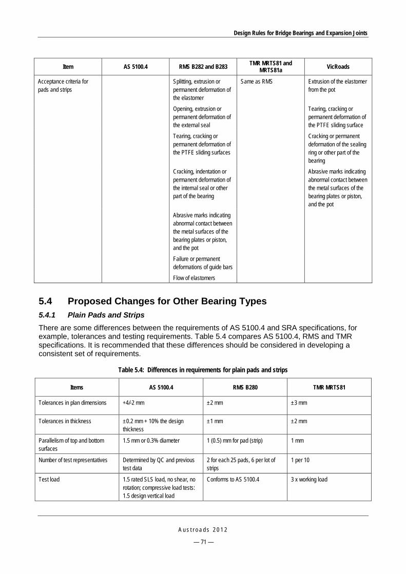
Design Rules for Bridge Bearings and Expansion Joints
A u s t r o a d s 2 0 1 2
— 71 —
Item AS 5100.4 RMS B282 and B283 TMR MRTS81 and MRTS81a VicRoads
Acceptance criteria for pads and strips
Splitting, extrusion or permanent deformation of the elastomer
Same as RMS
Extrusion of the elastomer from the pot
Opening, extrusion or permanent deformation of the external seal
Tearing, cracking or permanent deformation of the PTFE sliding surface
Tearing, cracking or permanent deformation of the PTFE sliding surfaces
Cracking or permanent deformation of the sealing ring or other part of the bearing
Cracking, indentation or permanent deformation of the internal seal or other part of the bearing
Abrasive marks indicating abnormal contact between the metal surfaces of the bearing plates or piston, and the pot
Abrasive marks indicating abnormal contact between the metal surfaces of the bearing plates or piston, and the pot
Failure or permanent deformations of guide bars
Flow of elastomers
5.4 Proposed Changes for Other Bearing Types 5.4.1 Plain Pads and Strips There are some differences between the requirements of AS 5100.4 and SRA specifications, for example, tolerances and testing requirements. Table 5.4 compares AS 5100.4, RMS and TMR specifications. It is recommended that these differences should be considered in developing a consistent set of requirements.
Table 5.4: Differences in requirements for plain pads and strips
Items AS 5100.4 RMS B280 TMR MRTS81
Tolerances in plan dimensions +4/-2 mm ±2 mm ±3 mm
Tolerances in thickness ±0.2 mm + 10% the design thickness
±1 mm ±2 mm
Parallelism of top and bottom surfaces
1.5 mm or 0.3% diameter 1 (0.5) mm for pad (strip) 1 mm
Number of test representatives Determined by QC and previous test data
2 for each 25 pads, 6 per lot of strips
1 per 10
Test load 1.5 rated SLS load, no shear, no rotation; compressive load tests: 1.5 design vertical load
Conforms to AS 5100.4 3 x working load

Design Rules for Bridge Bearings and Expansion Joints
A u s t r o a d s 2 0 1 2
— 72 —
Items AS 5100.4 RMS B280 TMR MRTS81
Tolerances on compressive stiffness
Not specified ±20% the mean value of test samples
Not specified
Tolerances on shear stiffness ±20% the design value ±20% the values given in table B280.2 for 2 pad sizes and 4 strip sizes
Not specified
Non-acceptance criteria Not specified Splitting, permanent deformation, significantly irregular or unsymmetrical surface bulging
No surface split, indentations, evidence of incomplete vulcanising of the rubber compound
5.4.2 Mechanical Bearings Mechanical bearings are no longer used by SRAs except in special cases.

Design Rules for Bridge Bearings and Expansion Joints
A u s t r o a d s 2 0 1 2
— 73 —
6 PROPOSED BEARING SPECIFICATION DEVELOPMENT
6.1 Background Spherical bearings and disc bearings have been used in overseas as an alternative for pot bearings when the gravity load or the required rotation is large. They are able to support loads of up to several thousand tonnes and may accommodate rotations of more than five degrees if the bearing is properly designed and constructed.
Overseas specifications such as AASHTO LRFD and EN 1337 have provisions specifying the requirements for design of spherical and disc bearings while AS 5100.4 does not yet do so. A need has been identified for a generic specification for the design of these bearing types to be developed for use in Australia.
Local manufacturers have introduced spherical bearings and prepared for future bridge applications (Section 3.3.1).
The generic specification proposed in this section is based on the AASHTO LRFD specifications (AASHTO 2010).
6.2 Generic Specification for Spherical and Disc Bearings 6.2.1 General Requirements Movement and loads
Bearings shall be designed to resist loads and accommodate movements at the SLS and ULS.
The minimum thermal movements shall be determined from the extreme temperature specified in Clause 17, AS 5100.2 and the estimated setting temperatures. Design loads shall be based on the load combinations and load factors specified in Clause 22, AS 5100.2.
The maximum ULS rotation due to the total load for spherical bearings which may potentially experience hard contact between metal components shall be taken as the sum of:
the rotations from applicable ultimate load combinations
the maximum rotation caused by fabrication and installation tolerances, which shall be taken as 0.005 rad, unless an approved quality control plan justifies a smaller value
an allowance for uncertainties, which shall be taken as 0.005 rad, unless an approved quality control plan justifies a smaller value.
The maximum ULS rotation due to the total load for disc bearings which are less likely to experience hard contact between metal components shall be taken as the sum of:
the rotations from applicable ultimate load combinations
an allowance for uncertainties, which shall be taken as 0.005 rad, unless an approved quality control plan justifies a smaller value.
Sliding surface
Sliding surfaces consist of flat sliding surfaces which accommodate translational movements, and curved sliding surfaces which accommodate translational and limited rotation.

Design Rules for Bridge Bearings and Expansion Joints
A u s t r o a d s 2 0 1 2
— 74 —
The sliding surface material shall be PTFE, bronze or copper alloy or an approved proprietary material.
PTFE sliding surfaces shall meet the requirements specified in Clause 14, AS 5100.4.
Bronze sliding surfaces shall conform to AASHTO M 107 (ASTM B22) and shall be made of alloy C90500, C91100, or C86300, unless otherwise specified. Bronze or copper alloy sliding expansion bearings shall be evaluated for shear capacity and stability under lateral loads.
Mating surface
The PTFE or an approved proprietary sliding material shall be used in conjunction with a mating surface. Flat mating surfaces shall be stainless steel, and curved mating surfaces shall be stainless steel or anodised aluminium. Flat surfaces shall be stainless steel, Type 304, conforming to either ASTM A167 or A264, and shall be provided with a surface finish of 8.0 pin. RMS or better. Finishes on curved metallic surfaces shall not exceed 16.0 pin. RMS. The mating surface shall be large enough to cover the PTFE at all times.
For bronze sliding surfaces, the mating surface shall be structural steel, and be machined to match the geometry of the bronze surfaces so as to provide uniform bearing and contact. The mating surface shall have a Brinell hardness value at least 100 points greater than that of the bronze.
Contact pressure
The contact stress between the PTFE and the mating surface shall be determined at the ULS using the nominal area.
The average contact stress shall be computed by dividing the load by the projection of the contact area on a plane perpendicular to the direction of the load. The contact stress at the edge shall be determined by taking into account the maximum moment transferred by the bearing assuming a linear distribution of stress across the PTFE. Stresses shall not exceed the values given in Table 6.1.
Table 6.1: Maximum contact stress for PTFE at the ULS
Material Average contact stress (MPa) Edge contact stress (MPa)
Permanent loads All loads Permanent loads All loads
Unconfined PTFE: Unfilled sheets Filled sheets with maximum filler content
10.3 20.6
17.2 31.0
13.8 24.0
20.6 38.0
Confined sheet PTFE 2.06 31.0 24.0 38.0
Woven PTFE fibre over a metallic subtrate 20.6 31.0 24.0 38.0
Reinforced woven PTFE over a metallic subtrate 27.6 38.0 31.0 48.3
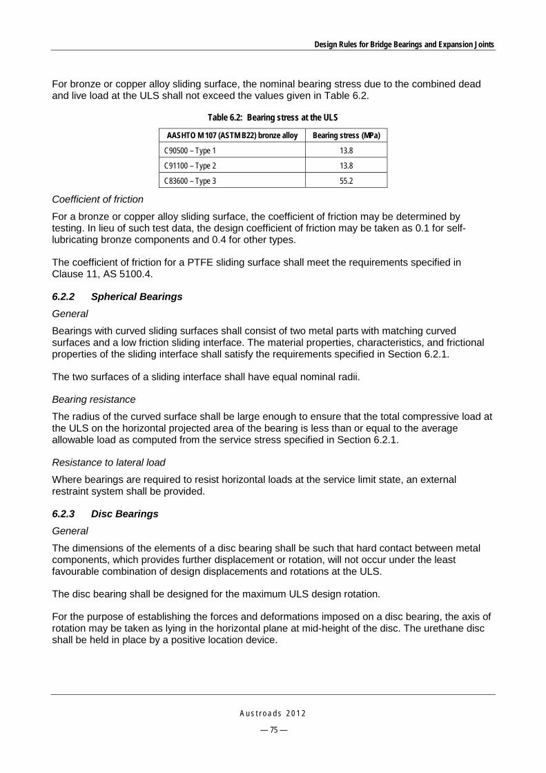
Design Rules for Bridge Bearings and Expansion Joints
A u s t r o a d s 2 0 1 2
— 75 —
For bronze or copper alloy sliding surface, the nominal bearing stress due to the combined dead and live load at the ULS shall not exceed the values given in Table 6.2.
Table 6.2: Bearing stress at the ULS
AASHTO M 107 (ASTM B22) bronze alloy Bearing stress (MPa)
C90500 – Type 1 13.8
C91100 – Type 2 13.8
C83600 – Type 3 55.2
Coefficient of friction
For a bronze or copper alloy sliding surface, the coefficient of friction may be determined by testing. In lieu of such test data, the design coefficient of friction may be taken as 0.1 for self-lubricating bronze components and 0.4 for other types.
The coefficient of friction for a PTFE sliding surface shall meet the requirements specified in Clause 11, AS 5100.4.
6.2.2 Spherical Bearings General
Bearings with curved sliding surfaces shall consist of two metal parts with matching curved surfaces and a low friction sliding interface. The material properties, characteristics, and frictional properties of the sliding interface shall satisfy the requirements specified in Section 6.2.1.
The two surfaces of a sliding interface shall have equal nominal radii.
Bearing resistance
The radius of the curved surface shall be large enough to ensure that the total compressive load at the ULS on the horizontal projected area of the bearing is less than or equal to the average allowable load as computed from the service stress specified in Section 6.2.1.
Resistance to lateral load
Where bearings are required to resist horizontal loads at the service limit state, an external restraint system shall be provided.
6.2.3 Disc Bearings General
The dimensions of the elements of a disc bearing shall be such that hard contact between metal components, which provides further displacement or rotation, will not occur under the least favourable combination of design displacements and rotations at the ULS.
The disc bearing shall be designed for the maximum ULS design rotation.
For the purpose of establishing the forces and deformations imposed on a disc bearing, the axis of rotation may be taken as lying in the horizontal plane at mid-height of the disc. The urethane disc shall be held in place by a positive location device.

Design Rules for Bridge Bearings and Expansion Joints
A u s t r o a d s 2 0 1 2
— 76 —
Limiting rings may be used to partially confine the elastomer against lateral expansion. They may consist of steel rings welded to the upper and lower plates or a circular recess in each of those plates.
If a limiting ring is used, the depth of the ring should be at least 0.03 Dd, where Dd is the diameter of the disc element.
Material
The elastomeric disc shall be made from a compound based on polyether urethane, using only virgin materials. The hardness shall be between 45 and 65 on the Shore D scale.
The metal components of the bearing shall be made from structural steel conforming to AS/NZS 3678 and/or AS/NZS 3679.1 or from stainless steel conforming to ASTM A240/A240M Grade 316L.
Elastomeric disc
The elastomeric disc shall be held in location by a positive locator device.
At the ULS, the disc shall be designed so that:
Its instantaneous deflection under total load does not exceed 10% of the thickness of the unstressed disc, and the additional deflection due to creep does not exceed 8% of the thickness of the unstressed disc.
The components of the bearing do not lift off each other at any location.
The average compressive stress on the disc does not exceed 35 MPa. If the outer surface of the disc is not vertical, the stress shall be computed using the smallest plan area of the disc.
If a PTFE slider is used, the stresses on the PTFE slider shall not exceed the values for average and edge stresses given in Table 6.1 for the ULS. The effect of moment induced by the urethane disc shall be included in the stress analysis.
Shear resisting mechanism
In fixed and guided bearings, a shear-resisting mechanism shall be provided to transmit horizontal forces between the upper and lower steel plates. It shall be capable of resisting the calculated horizontal force in any direction at the ULS or 15% of the design vertical load at the ULS, whichever is larger.
Steel plates
The thickness of each of the upper and lower steel plates shall not be less than 0.045 Dd, where Dd is the diameter of the disc element, if it is in direct contact with a steel girder or distribution plate, or 0.06 D, if it bears directly on grout or concrete.

Design Rules for Bridge Bearings and Expansion Joints
A u s t r o a d s 2 0 1 2
— 77 —
7 CONCLUSION AND FUTURE DIRECTIONS The project has involved a literature review, consultation with manufacturers and consultation with SRAs to identify the most common modes of failure of bridge bearings in Australia. The following conclusions are noted:
A number of failure modes have been reported in both the literature and current Australian practice.
The root causes of failures may come from all stages including design, manufacture, installation and maintenance. However, the most common cause of failures relates to the installation stage.
In addition to following AS 5100.4, each SRA has developed and/or used its own technical guidelines and specifications. The requirements, particularly in materials and testings, vary significantly, creating a level of inconsistency throughout the SRAs and difficulties for manufacturers, suppliers and contractors.
There is a lack of consistent procedures for acceptance and control measures of new products, especially of imported products.
New types of modern bridge bearing systems have been introduced in Australia, such as spherical bearings and disc bearings. However, comprehensive specifications for the design, installation and maintenance of these bearing types are lacking.
The recommendations made in Section 5 can be used as design rules to assist in overcoming the performance issues for each type of bearing.
Section 6 can be used as the basis to develop generic specifications for spherical and disc bearings.

Design Rules for Bridge Bearings and Expansion Joints
A u s t r o a d s 2 0 1 2
— 78 —
PART II – EXPANSION JOINTS
Design Rules for Bridge Bearings and Expansion Joints
A u s t r o a d s 2 0 1 2
— 79 —
1 INTRODUCTION The contents of Part 2 – Bridge Expansion Joints are briefly summarised below.
Section 2 presents a literature review that summarises the features, usage and performance of bridge expansion joints throughout the world. Thus, the common failures of the common types of expansion joint are identified.
Section 3 describes the current practice in manufacture and supply of bridge expansion joints of some popular Australian providers.
Section 4 describes SRAs’ experience in design, installation and maintenance of bridge expansion joints. Common failure modes of various types of expansion joints are derived from SRAs’ information, based on which the key issues in design, manufacture, construction and maintenance of bridge expansion joints are identified.
Section 5 presents an investigation into failures of some common bridge expansion joint types that have been used in the past and will be continued in new bridge designs, and proposes changes to the current version of the Australian Bridge Design Standard AS 5100 part 4. Proposed changes for other expansion joint types are also addressed in this section.
Section 6 presents a generic specification for bridge expansion joints in which specific provisions for several popular expansion joint types are provided.
Section 7 represents the key conclusions arising from the project.

Design Rules for Bridge Bearings and Expansion Joints
A u s t r o a d s 2 0 1 2
— 80 —
2 LITERATURE REVIEW ON EXPANSION JOINTS
2.1 General 2.1.1 Historical Development Similar to the development of bearings, expansion joints have been used since early longer span cast iron and steel bridges replaced the massive volume stone or masonry bridges in the early 19th century. Together with the development of bridge structures, various types of expansion joints have been developed to suit a range of joint movements. These types of joints, after being used for some time, have been improved based on their field performance and lessons learnt from experience. Three groups can be identified by the range of movement: small, medium and large movement joints.
The first use of sealers for expansion joints in bridges was either to leave them open or to pour some mixture of tar or asphalt in them. The tar-like material did not work at all in the relatively narrow contraction joints, while in the case of the much wider expansion joints, it usually ran out of the bottom of the joint (Watson 2006).
Rubber asphalt materials were used later with some types of seal stop at the joint to prevent the sealer from falling to the bottom. However, the constantly moving joint interfaces shortened their useful life. Rubber asphalts were then improved with butyls, polysulfides, urethanes, silicones, and variations were tried with most of them having shortcomings.
Poured-in-place sealants were introduced some 50 years ago. The current forms of these materials include bitumen, polyurethanes, two-part pack polyester polyurethanes, rubberised bitumen, megaprene and polymer modified bitumens (QMR 2004).
Preformed compression joint seals were first used in 1960 which consisted of a compartmented vulcanisate of a compound primarily of polychloroprene, plasticisers, carbon black, antiozodents and conventional synthetic rubber requirements. With various types of seal configurations, current practice shows that this joint type is one of the most favourable expansion joints for small to medium movements.
Strip seal joints were developed in 1970 by Waldermar Koster, they originated from compression seal joints by adapting the top portion only and arranging a claw to accept the sides of the rubber strip. Combined with different types of metal runners from many manufacturers, this type of joint has been used widely for medium to large joint movements.
Felspan is a moulded rubber joint type, which was first produced by the Felt Products Company in 1978 in the USA. It is no longer used in new bridge construction due to its shortcomings.
The first bonded metal/elastomer joints were used in 1970 with the brand name of Transflex (General Tire & Rubber Company, US) with neoprene surface. This joint type dominated the expansion joint market in the US from 1975 to 1985. Leakage and wear of the rubber under heavy truck traffic, however, were some of its shortcomings. The Waboflex expansion joint, which was introduced in 1972, is a variant of this joint in which a high strength ribbed, anti-skid aluminium was placed on the top surface instead of the neoprene surface (Watson 2006). These two expansion joint types continue to be used in new bridge constructions for medium to large joint movements.

Design Rules for Bridge Bearings and Expansion Joints
A u s t r o a d s 2 0 1 2
— 81 —
Finger type joints and modular expansion joints have been introduced since the 1960s for very large movements. The performance of these joint types has been improved significantly since, in order to keep up with the increasingly complex requirements of modern bridge structures.
2.1.2 Functions of Expansion Joints Expansion joints are an integral component of a bridge with a key role to ensure the structure performs in a predefined structural arrangement. The selection of a suitable expansion joint at the design stage is based on various factors such as the type of bridge structure, material, span, usage, and climatic conditions. Principally, expansion joints must meet the following conditions:
accommodate all ranges of movements induced by all actions acting on the bridge
sustain impact and vibration of traffic and other actions (direct and indirect)
provide a good surface for all classes of road user
restrict noise levels to a reasonable level
remain serviceable under different climatic conditions and chemical agent impacts
prevent grit, debris and water from damaging the underneath bridge components
allow easy installation, inspection, maintenance and replacement
provide total service life cost-effectiveness.
2.1.3 General Design Considerations The main selection criterion for bridge expansion joints is the magnitude of movements, including contraction and expansion. These values can be obtained by the combination of the most severe conditions. The maximum joint gap may occur during the coldest day combined with maximum creep and shrinkage (after 30 years). Similarly, the minimum gap may occur on the hottest day combined with minimum creep and shrinkage (right after joint installation for new bridges).
2.2 Common Types of Expansion Joints A summary of common types of expansion joints with detailed descriptions, movement ranges, advantages/disadvantages, reported defects and comments can be found in Austroads (2001).
2.2.1 Steel Sliding Plate Joints Joint features
Steel sliding plate joints have been used extensively in the past for concrete and timber bridges with small movement ranges. A sliding plate joint consists of two overlapping steel plates attached to either side of the bridge deck. The widths of the steel plates are selected to cover the range of movements, and the thickness of the plates is determined by structural requirements. Figure 2.1 shows a typical arrangement for a steel sliding plate joint.
This type of joint does not provide a complete seal against water or debris reaching the underneath substructure.

Design Rules for Bridge Bearings and Expansion Joints
A u s t r o a d s 2 0 1 2
— 82 —
Source: Chen and Duan (2000).
Figure 2.1: Steel sliding plates
Reported failures
The following failures have been reported:
corrosion of the steel plate and debris collection obstructing the free movement of the superstructure
loose and broken anchorages due to repeated impact and weathering actions.
This joint is not recommended for new bridge construction. Existing steel sliding plate joints can be replaced by poured sealants or elastomeric strip seals (Chen & Duan 2000).
2.2.2 Asphaltic Plug Joints Joint features
The asphaltic plug joint is a form of the buried joint. It consists of a band of cast-in-situ flexible materials supported over the joint gap by thin plates. The flexible material consists of binders and coarse aggregate to provide not only flexibility to accommodate movements, but also strength for the running surface at road level. The binders are typically based on bitumens modified with plasticisers and polymers, and the coarse aggregate is usually of the basalt group. The thin plate is installed across the gap to prevent the flexible material from being extruded into the gap under traffic loading (Figure 2.2).
This joint can accommodate movements of less than 50 mm (Barnard & Cunninghame 1997).
Advantages of asphaltic plug joints include low initial cost, short installation time and ease of replacement. In addition, they can accommodate some variations in surfacing depth or deck geometry and also can be replaced in separate sections which assist with minimising traffic delays.
In some cases, however, the joint material has been found to be too flexible under extreme weather, i.e. softened under hot days and hardened and cracked in cold days (Chen & Duan 2000). The performance and service life also varies, depending on various factors such as thermal and traffic induced movements, installation conditions and stability of surfacing.

Design Rules for Bridge Bearings and Expansion Joints
A u s t r o a d s 2 0 1 2
— 83 —
Reported failures
The most common failure of this type of joint is cracking along the joint edges, which leads to water leakage, debonding or depression over the joint. Flexibility of the binder may also cause it to flow over an adjacent road surface. Potholing and loss of aggregate have been reported (Barnard & Cunninghame 1997).
Source: Chen and Duan (2000).
Figure 2.2: Asphaltic plug joint
It has been reported that the service life of the joint is 2-5 years in the UK and in general, the performance of the joint is not appropriate for movements between 30 mm to 50 mm (Austroads 2001).
RMS has banned this joint type and only allows it for special site conditions where excessive noise cannot be treated by another joint type (RTA 2008b).
2.2.3 Cold Applied Sealant Joints Pourable sealant joints consist of rapid curing, elastomeric sealants typically used for small movement joints with a sealed join width up to 40 mm (Figure 2.3).
The sealants of this type may include: silicon (-50%, +100%), polysulphide (±12.5%) or polyurethane (±25%) based sealants. The advantages of this joint type include good chemical resistance, excellent movement recovery and self-levelling or non-sag.
This type of joint has been used in the USA for movements of less than 12 mm (Austroads 2001). Advantages include material savings, elimination of field working time, shop drawing and engineered steel fabrications (Baker & Adams 1996).
In Australia, it is used widely by RMS for short bridges with a movement range of up to about 20 mm (RTA 2008b).

Design Rules for Bridge Bearings and Expansion Joints
A u s t r o a d s 2 0 1 2
— 84 —
Source: Chen and Duan (2000).
Figure 2.3: Pourable sealant joint
2.2.4 Compression Seal Joints Joint features
Compression seals are compressed when inserted into the joint gap and remain in the compressive state during all possible movements. This joint includes a preformed or hollow extruded elastomer in various web configurations installed in-between concrete or steel angle armorings (Figure 2.4). The working width of the seal varies generally from 85%, at the minimum joint movement, to approximately 40% of the nominal width at the maximum joint movement (Chen & Duan 2000).
This joint can be used for movements of less than 100 mm. Together with the relative ease of installation, cost-effectiveness, a large variety of choices in movement ranges and watertightness, this joint type has been used widely for small and medium span bridges.
Reported failures
Common failures of this joint type include dislodgement of the seal, damage or deterioration of seal material, and cracked or broken nosings (Issa et al. 1996, Chang & Lee 2002).
The performance of the joint depends on the quality of the installation and the correct choice of the seal size and seal material – that requires skillful workmanship and careful design consideration. In addition, waterproofing is not continuous hence a complete water drainage system needs to be provided. Compression seals may be ozone sensitive (Austroads 2001).

Design Rules for Bridge Bearings and Expansion Joints
A u s t r o a d s 2 0 1 2
— 85 —
Source: Chen and Duan (2000).
Figure 2.4: Compression seal joint
2.2.5 Strip Seal Joints Joint features
A strip seal is a form of prefabricated compression seal joint which consists of an elastomeric seal between metal runners. This joint type can accommodate movements up to 100 mm. The seal may have various configurations. Metal runners can be steel or aluminum and have an anchorage system, which can be in a heavy duty form or a standard form (Figure 2.5).
Strip seal joints have a number of advantages including:
high durability
low stiffness
good watertightness
the joint can accommodate vertical or skew movements
the seal can be replaced without damaging the metal runners.
Disadvantages of this joint include:
performance depends on correct choice of seal size and seal material
corrosion of metal components
collection of debris between runners
waterproofing is not continuous
accumulation of debris, leakage and noise under traffic.

Design Rules for Bridge Bearings and Expansion Joints
A u s t r o a d s 2 0 1 2
— 86 —
Reported failures
Common failures of this joint type include (Dahir & Mellott 1987, Barnard & Cunninghame 1997, and Austroads 2001):
elastomeric seal punctures or breaks up
failure to the anchorage of metal runners
transition strip or surfacing breaks up next to nosing
fatigue of metal components.
Field splicing of the seal is not permitted as the quality of the splice is not good. Instead, the splice is vulcanised in factory using a hot or cold process. The extrusion and plate assemblies with anchors are shop fabricated and installed in one continuous length. The reported life of the joint is 10-20 years (Austroads 2001).
Source: Chen and Duan (2000).
Figure 2.5: Strip seal joint
2.2.6 Moulded Rubber Joints Joint features
The moulded rubber joint is another form of strip seal joint. It consists of a sheet of reinforced elastomeric membrane across the joint gap and moulded rubber pads anchored to the concrete at either side of the joint (Figure 2.6). Deformation of the membrane accommodates deck movements, which are in the range of 50 mm to 100 mm. The most common type is the Felspan joint.

Design Rules for Bridge Bearings and Expansion Joints
A u s t r o a d s 2 0 1 2
— 87 —
This joint has some ability to accommodate directional changes and skews in joint configuration often without any need for a splice in the seal.
Reported failures
The following failures have been reported (RTA 2008b):
failure of anchorage systems due to repetitive live load impacts
splitting of the seals and loosening of the retainers.
This joint was identified as having inadequate anchorages and exhibiting excessive wear of the elastomeric moulding around the retainers. In addition, the failure develops relatively rapidly after initiation. The RMS does not recommend this type of joint for new bridges (RTA 2008b).
Strip seal, bonded metal elastomer or fingerplate joints can be used to replace the damaged moulded rubber joint (RTA 2008b).
Source: RTA (2008b).
Figure 2.6: An example of moulded rubber joint
2.2.7 Bonded Metal/Elastomer Joints Joint features
This joint type consists of a reinforced elastomeric pad that bridges the join gap and is anchored to both sides of the gap. It accommodates the movements by deformation of the elastomer. The embedded metal plates help to strengthen the joint structure to sustain traffic loadings. This type of joint is relatively easy to install and may be suitable for large movements of 50-300 mm (Figure 2.7).
Main disadvantages of this joint include leakage at joints between segments, loose anchorages, and excessive noise. In addition, the bolt positions may clash with reinforcement and it is difficult to
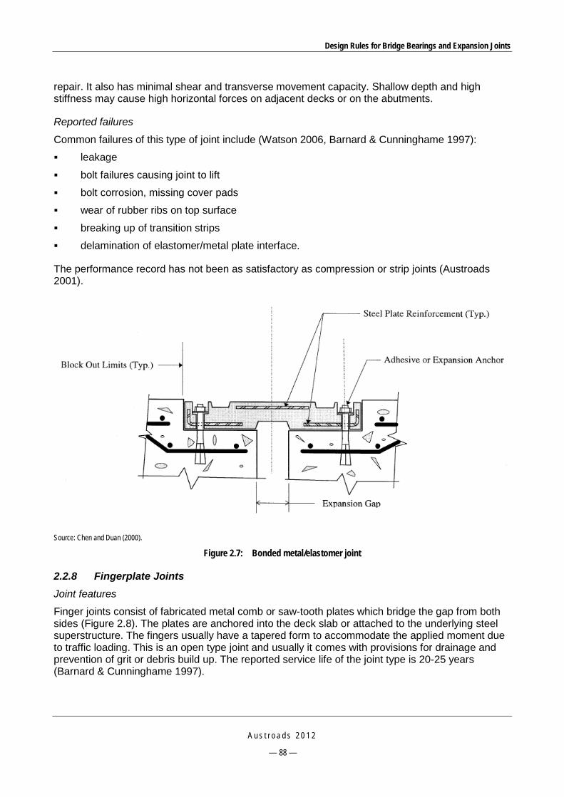
Design Rules for Bridge Bearings and Expansion Joints
A u s t r o a d s 2 0 1 2
— 88 —
repair. It also has minimal shear and transverse movement capacity. Shallow depth and high stiffness may cause high horizontal forces on adjacent decks or on the abutments.
Reported failures
Common failures of this type of joint include (Watson 2006, Barnard & Cunninghame 1997):
leakage
bolt failures causing joint to lift
bolt corrosion, missing cover pads
wear of rubber ribs on top surface
breaking up of transition strips
delamination of elastomer/metal plate interface.
The performance record has not been as satisfactory as compression or strip joints (Austroads 2001).
Source: Chen and Duan (2000).
Figure 2.7: Bonded metal/elastomer joint
2.2.8 Fingerplate Joints Joint features
Finger joints consist of fabricated metal comb or saw-tooth plates which bridge the gap from both sides (Figure 2.8). The plates are anchored into the deck slab or attached to the underlying steel superstructure. The fingers usually have a tapered form to accommodate the applied moment due to traffic loading. This is an open type joint and usually it comes with provisions for drainage and prevention of grit or debris build up. The reported service life of the joint type is 20-25 years (Barnard & Cunninghame 1997).

Design Rules for Bridge Bearings and Expansion Joints
A u s t r o a d s 2 0 1 2
— 89 —
The finger joint is one of the most silent joint types as there is no sliding surface. As it is an open type joint, there is no thrust on the deck or abutments. Being able to accommodate movements of 100-600 mm which covers a large portion of modern bridges, finger joints are one of the most favorable joints for current and future bridges.
Some drawbacks include high initial cost, possible accumulation of debris and limited lateral movement (Austroads 2001).
Reported failures
Various failure modes have been reported in the literature (Dahir & Mellott 1987, Lee 1994, Barnard & Cunninghame 1997, Watson 2006) including:
fatigue failure of fingers, bolts and their anchorage due to their working cantilevered under repetitive loading
corrosion of metals in the vicinity of the joint area
transition strip breaks up
comb fills up with debris
low skid resistance on metal comb
failure of concrete anchorage.
Source: Moor (2006).
Figure 2.8: Finger type expansion joint
For all-purpose roads, provisions need to be made for cyclists, pedestrians and animals due to the large gap between fingers. A separate trough system must be installed to collect water and debris. Loose fingerplates may be hazardous to traffic. Fingers and their troughs need to be cleaned periodically.
2.2.9 Modular Joints Joint features
The modular bridge joint system (MBJS) consists of a series of compression seals between centre beams and edge beams which are supported by cross support bars and bearings. Both longitudinal and transverse movements are allowed by sliding bearings on sliding plates. Seals and centre beams form a watertight surface at the riding surface level. Support bars span the opening. The whole joint is anchored to both sides of the deck by an anchor system (Figure 2.9). Two types

Design Rules for Bridge Bearings and Expansion Joints
A u s t r o a d s 2 0 1 2
— 90 —
of MBJS are popular, being the single and multiple support bar system, including the swivel joist system.
Having a number of advantages that are suitable for complex features in modern bridges such as large movements of up to 1000 mm, non-parallel horizontal movements, different settlement, rotation, and high shearing movements, this joint type is favoured for many situations in modern design. The design life of the joint is reportedly 10-20 years (Barnard & Cunninghame 1997).
Reported failures
Various failure modes have been reported in the literature (Kaczinski et al. 1996, Ancich & Chirgwin 2006, Fleuriot et al. 2006). They include:
noise under live load impact
water leakage at seal splice
debris accumulation in seals
reflective cracks in the concrete deck directly above the support boxes
fatigue cracks
corrosion of metal components.
Source: Megaba’s website.
Figure 2.9: Example of a modular expansion joint
The multiple support bar system is usually the preferred choice as it has more redundancy compared to the single support bar system, that is, failure of a single support bar bearing will not affect the whole system (Fleuriot et al. 2006). For large movement joints however, the single support bar system should be considered because if the multiple support bar system is chosen, a large number of support boxes are used, thus the adjacent boxes may touch each other.
Close cooperation between the designer, contractor and joint manufacturer is required to ensure good detail design, and to reduce placement problems during joint installation (AASHTO 2004).

Design Rules for Bridge Bearings and Expansion Joints
A u s t r o a d s 2 0 1 2
— 91 —
2.3 Design Codes/Specifications 2.3.1 Australian Bridge Design Standard AS 5100 The requirements for design and installation of bridge expansion joints are specified in Part 4 of AS 5100 (2004). It covers the following joint types:
compression seals
strip seals
fingerplates
asphaltic plug joints
modular.
The following requirements are highlighted:
Anti-skid treatment shall be provided for any metal surface wider than 200 mm that is exposed to vehicle traffic.
For structural design of deck joints, a vertical axle load (A160) and a longitudinal live load of minimum 35% of the vertical load acting at the road level parallel to the direction of traffic, shall be used to design the joint structure. The dynamic load allowance is 0.6 except for the modular deck joints, which shall be determined from specialist studies, taking into account the dynamic characteristics of the joint. The load factor shall be 1.8 for ULS effects, 1.0 for ULS effects and 0.6 for fatigue limit state effects, respectively.
Deck joints shall be designed to accommodate ULS movements.
The maximum roadway surface gap of a parallel-sided deck joint, at the ultimate movement limit, measured perpendicular to the joint, shall be 85 mm.
For fingerplate joints the maximum opening between adjacent fingers on the same side of the joint shall be 50 mm and the minimum overlap of the fingers on the opposite side of the joint shall be 15 mm.
Sufficient anchorage is required to transfer all static and dynamic loads from the joints to the structure.
A drainage system is required to cater for any percolation of water that may occur.
For modular deck joints, only modular deck joints that have been tested and that comply with the fatigue test specification of NCHRP 402 (Dexter et al. 1997), or equivalent internationally recognised specification, shall be accepted.
For joint sealants, it is specified that sealants not be subjected to more than 25% strain in compression or tension.
For bridge deck joints, AS 5100.4 is very generic, i.e. no detailed design requirement of a specific joint type is specified.
2.3.2 AASHTO LRFD Bridge Design Specification The main provisions for bridge expansion joints specified in the AASHTO LRFD Bridge Design Specifications (AASHTO 2010) are summarised below. Only provisions that are different from AS 5100.4 or are of significant importance are listed.

Design Rules for Bridge Bearings and Expansion Joints
A u s t r o a d s 2 0 1 2
— 92 —
Movements and loads
The following factors should be considered in the design of modular bridge joint system (MBJS):
properties of materials in the structure
size of structural components
translational and rotational movements of the bridge caused by loads, deformations, creep, shrinkage and thermal effects, inaccuracies in installation
construction method, sequence and tolerances
effects of curvature, skew, rotations and support restraint
forces resulting from transverse or longitudinal prestressing of the superstructure
resistance of the joints to movements
substructure and foundation movements
influence of dynamic load allowance
rotations about two horizontal axes and the vertical axis
three-dimensional effects of translational and rotational movements of the bridge
instantaneous and long-term effects.
Materials
Elastomers for joint seals and troughs shall have a service life of no less than 25 years while other materials shall provide a minimum 75 years of service life.
Joint selection
The number of movable deck joints should be minimised. Continuous deck systems and superstructures are preferred. Intermediate deck joints should be considered for multiple span bridges where differential settlement would cause significant overstresses.
Design requirements
The roadway surface gap shall not be greater 100 mm for a single gap or 75 mm for multiple modular gaps.
For fingerplate joints, the maximum allowable opening between adjacent fingers shall be 50 mm for longitudinal gaps greater than 200 mm or 75 mm for longitudinal gaps less than or equal 200 mm. The finger overlap should be 40 mm minimum.
Considerations for specific joint types
Open joints: should not be used where de-icing chemicals are applied. Provisions to prevent the accumulation of water and debris should be made for the piers and abutments.
Closed joint: joint seals should be watertight and extrude debris when closing. The elastomer glands or membranes shall not be directly in contact with vehicle wheels when joint movement occurs by a change in their geometry.
Waterproof joints: the drainage trough shall be prefabricated from reinforced elastomers, stainless steel or other metal with durable coatings. The trough shall discharge easily, be replaceable from below the joint and be able to flush from the roadway surface.

Design Rules for Bridge Bearings and Expansion Joints
A u s t r o a d s 2 0 1 2
— 93 —
Joint seals: the joint seals shall be a preformed or prefabricated type, made from vulcanised virgin neoprene or natural rubber and reinforced with steel or fabric laminates. They shall be mechanically anchored, placed in one continuous piece and replaceable. In addition, they shall not be in direct contact with the vehicle load.
Poured seals: the joint width for poured seals should be at least 6 times the anticipated factored joint movement.
Compression and cellular seals: the width of the compression seals for bearing joints shall not be less than 65 mm nor more than 150 mm when uncompressed and shall be in 12.5 mm increments.
Sheet and strip seals: consideration should be given to:
— joint designs for which the glands with anchorages are not exposed to vehicular loadings
— joint designs that allow complete closure without detrimental effects to the glands
— joint designs where the elastomeric glands extend straight to the deck edges rather than being bent up at kerbs or barriers.
Plank seals: should be limited to structures on secondary roads with light truck traffic, and that have straight or slightly skewed joints.
MBJS
The specifications set out the requirements for the two common types of MBJS, single and multiple support bar systems, including swivel joist systems, as follows:
Performance requirements: In addition to the maximum movement and rotation capability requirements of seals in the MBJS, the required minimum movement range capabilities for the six degrees of freedom shall be added so that the seals can be able to eject the debris collected (Table 2.1).
Table 2.1: Minimum movement range capacity for MBJS
Type of movement Minimum design movement range
Longitudinal displacement Estimated movement +25 mm
Transverse movement 25 mm
Vertical movement 25 mm
Rotational around longitudinal axis 1o
Rotational around transverse axis 1o
Rotational around vertical axis 0.5o
Testing and calculation requirements: The following tests are required for testing of MBJS
— The opening movement and vibration (OMV) test is used for bearings, springs and other elastomeric components.
— The seal push-out (SPO) test is used to address the particular problem of seal detachment from centre beams.
— The fatigue test establishes the appropriate fatigue detail categories for the connection between centre beam and support bar, splices and other critical details. The category is then considered applicable to the full range of configurations with different
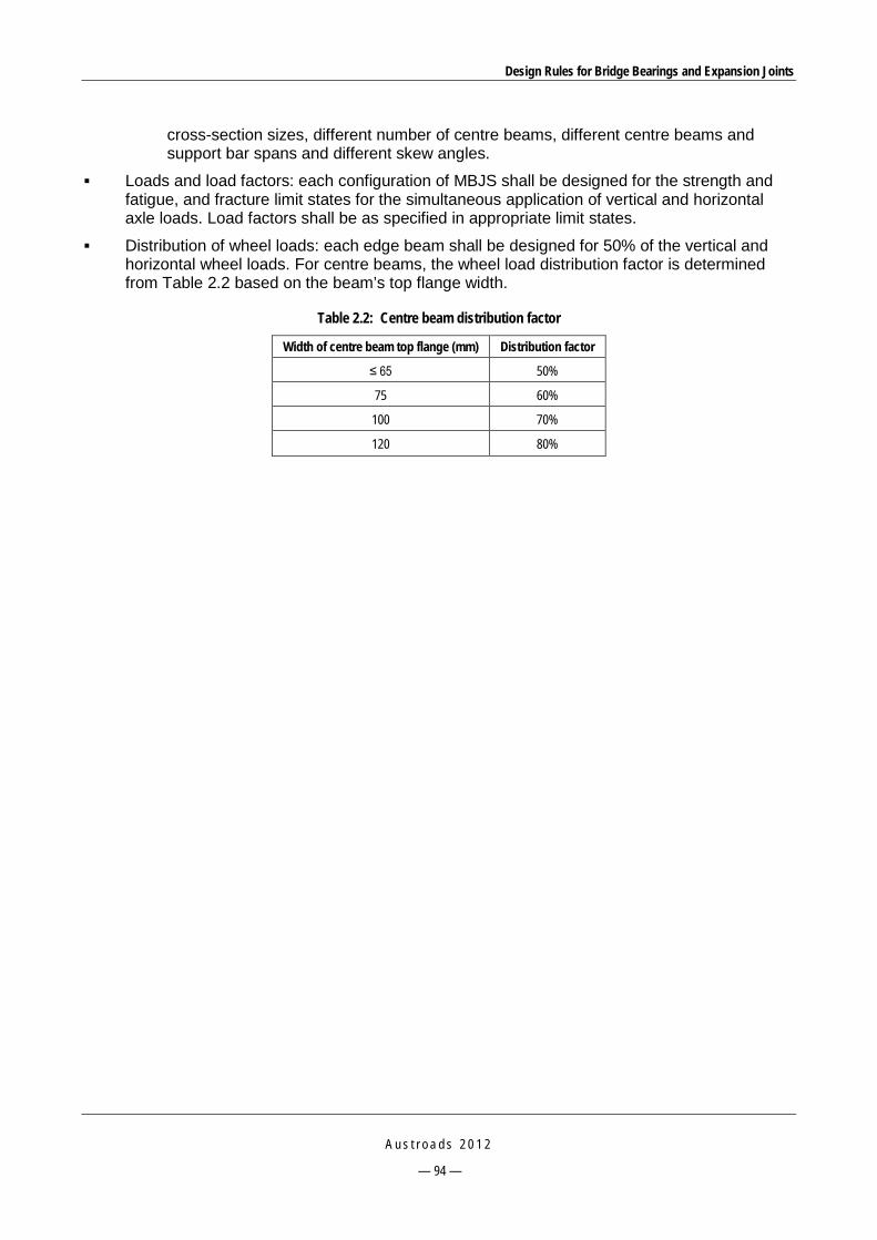
Design Rules for Bridge Bearings and Expansion Joints
A u s t r o a d s 2 0 1 2
— 94 —
cross-section sizes, different number of centre beams, different centre beams and support bar spans and different skew angles.
Loads and load factors: each configuration of MBJS shall be designed for the strength and fatigue, and fracture limit states for the simultaneous application of vertical and horizontal axle loads. Load factors shall be as specified in appropriate limit states.
Distribution of wheel loads: each edge beam shall be designed for 50% of the vertical and horizontal wheel loads. For centre beams, the wheel load distribution factor is determined from Table 2.2 based on the beam’s top flange width.
Table 2.2: Centre beam distribution factor
Width of centre beam top flange (mm) Distribution factor
≤ 65 50%
75 60%
100 70%
120 80%

Design Rules for Bridge Bearings and Expansion Joints
A u s t r o a d s 2 0 1 2
— 95 —
3 AUSTRALIAN MANUFACTURERS OF EXPANSION JOINTS
3.1 Granor 3.1.1 Types of Expansion Joints Manufactured Modular expansion joint
Granor supplies the Wabo modular joint. This joint is designed for heavy trafficked bridge structures that require large joint movements in excess of 160 mm (Figure 3.1).
Source: Granor website.
Figure 3.1: Wabo modular joint system
The key features of Wabo modular joint system are as follows:
high durability
good watertightness by the continuous elastomeric sealing elements
versatile in providing a smooth riding surface while absorbing the impact of heavy traffic
can be designed for curved structures or where the direction of thermal movement is not parallel to the bridge centre line, and it can accommodate skews up to 50 degrees
watertightness and ease of installation due to the use of mechanically locked strip seals and an inner locking single layer
multiple support bar systems provide the transmission of loads to the edges of the joint while allowing the joint to move freely in the expansion direction

Design Rules for Bridge Bearings and Expansion Joints
A u s t r o a d s 2 0 1 2
— 96 —
rigid connections between separation beams and support bars help reduce fatigue
resilient support structure including bearings and springs acts to dampen the dynamic loading, thus allows the joint system to accommodate thermal movements as well as rotations and deflections of the bridge
equidistance control system helps to distribute movements among strip seals to maintain equal spacing between separation beams and prevent excessive expansion of any single seal.
Finger joint
Granor supplies the ETIC finger joint. Three types are available, including the EJ 80, EJ 110 and EJ 160, which are designed for movements less than 80 mm, 110 mm and 160 mm, respectively.
This joint consists of metallic elements and an elastomeric profile. The metallic element is usually made of one metre long moulded aluminium pieces with a saw tooth profile and is anchored to the concrete deck by prestressed tie-bolts on each side of the joint. The elastomeric profile is of a compression seal type inserted between two extruded aluminium elements to prevent water or debris, etc. from penetrating to the sub-structure components.
Source: Granor website.
Figure 3.2: ETIC finger joint
The prestressed tie-bolts create a permanent compression stress between the joint and the structure, thus providing good resistance against vibrations and fatigue effects.
This joint possesses advantages such as low noise and no horizontal forces on the adjacent deck or abutment. In addition, it has good resistance to corrosion and the possibility of absorbing vertical and seismic movements.

Design Rules for Bridge Bearings and Expansion Joints
A u s t r o a d s 2 0 1 2
— 97 —
Strip seal expansion joint
Granor supplies two types of strip seal expansion joint, including the Ausflex Series AC and AC-AR cast-in aluminium bridge deck expansion joint system (Figure 3.3). The former is the standard type while the latter is the heavy duty type. This joint comprises a structural aluminium retainer at each side of the joint and a heavy duty elastomeric gland, which comes in two configurations, being type F and type D. The retainers are anchored to the bridge structure by a preloaded bolt cast-in fixing system (Figure 3.4). The strip seal can accommodate movements of up to 138 mm.
Source: Granor website.
Figure 3.3: Granor Ausflex strip joint
Source: Granor website.
Figure 3.4: Components of Granor Ausflex strip joint
This is one of the favoured joint types for maximum movements in the range of 65 to 138 mm. It features a number of advantages including ease of installation, watertightness and high corrosion resistance. In addition, the gland can accommodate skew and vertical misalignment, and can also be used to treat footpath, kerb or parapet upturn profiles.

Design Rules for Bridge Bearings and Expansion Joints
A u s t r o a d s 2 0 1 2
— 98 —
It is recommended that the type D gland not be used for pedestrian areas as the gap may be large under expansion. In such areas, type F is used instead.
Compression seals
Granor supplies two types of compression seal, including Wabo compression seals and Ausflex compression seals.
Wabo compression seals use two seal configurations, the WA series and WJ series, which can accommodate movements of 12 to 79 mm and are installed into the joint gap between armoured nosing plates (Figure 3.5).
Source: Granor website.
Figure 3.5: Wabo compression seals
There are three seal configurations in Ausflex compression seals, being EF, GC and WG series (Figure 3.6). The selection of a seal series is based on the movement range, i.e. EF is used for movements from 14 to 25 mm, GC 32 to 46 mm, and EF 35 to 60 mm. The seal is installed into either a concrete recess or steel angle armoured nosings. These joints are near watertight.
In addition, Granor supplies a special type, the Wizflex expansion joint system. This joint is designed based on a combination of compression joint and epoxy-bonded rubber seal technologies. It includes an extruded elastomeric profile, a high-strength epoxy adhesive and a compression seal profile design. The seal is bonded into the gap walls, which may be steel, concrete, polymer modified concrete or aluminium members, thus providing waterproof capability. (Figure 3.7).
WA Series WJ Series

Design Rules for Bridge Bearings and Expansion Joints
A u s t r o a d s 2 0 1 2
— 99 —
Source: Granor website.
Figure 3.6: Granor Ausflex compression seal
Source: Granor website.
Figure 3.7: Granor Wizflex expansion joint
Series EF Series GC Series WG
Concrete nosing Steel armoured nosing
Wizflex seal profile
An installed Granor Wizflex expansion joint

Design Rules for Bridge Bearings and Expansion Joints
A u s t r o a d s 2 0 1 2
— 100 —
Bonded metal/elastomer joints
Waboflex elastomeric expansion joints are supplied in 1.22 or 1.83 m moulded monolithic units. These units are reinforced with structural steel angles and imbedded wear plates that have skid resistance. Six sizes are available, which can accommodate movements of up to 330 mm (Figure 3.8).
Source: Granor website.
Figure 3.8: Two series of Waboflex joints
Cold applied sealant joint
The Granor-XJS system (Figure 3.9) is a cold applied rapid curing joint used for joint gaps of 25 to 75 mm in width and can accommodate movements of +100/-50% of the installation joint width. This system can be used to repair various types of joints including asphalt overlay, strip seal, and modular as well as joint nosings. Advantages of this system include low cost, fast set up, and ease of installation.
Source: Granor website.
Figure 3.9: Granor XJS expansion joint
Asphaltic plug joints
The Prismo-Thormajoint is an insitu hot poured joint type used for small movements of less than 50 mm (Figure 3.10). The flexible material BJ200 is available in a range of grades and is selected based on the site climate to ensure that it remains flexible in a very cold condition but does not

Design Rules for Bridge Bearings and Expansion Joints
A u s t r o a d s 2 0 1 2
— 101 —
become too stiff in a very warm condition. The aggregate BJ Stone is of the basalt, gritstone, gabbro or granite groups. If the gap is larger than 30 mm, an aluminium flashing strip is used to span the gap to prevent materials entering the gap during installation or service.
Source: Granor website.
Figure 3.10: Prismo-Thormajoint
3.1.2 Manufacturer Recommendations In an email from Oscar Velo (Granor) on 13 December 2010, comments on current practice and future directions were provided as below.
Common failures of expansion joints
Poor installation technique or workmanship is most often the root causes of premature expansion joint failures. Brief comments on specific types of expansion joints are provided below.
Sealants
The current definition of sealant does not adequately clarify if it is intended as a sealant or expansion joint filler. The most common sealant failure is the bond line failure due to poor preparation of the gap rebate surfaces.
AS 5100.4 limits the capacity of a sealant to only ± 25% of the installed gap width as the sealant’s movement design range. New generation sealant products such as silicone and urethane-based sealants, however, can claim up to +100 / -50% of the installed gap movement range.
Compression seals
This expansion joint type is now considered as ‘old technology’ but for many years was seen as the expansion joint for small movements. Long-term problems include stiffening, loss of compression set, falling through the gap, or protruding above the trafficked surface.
The seal may lose its ability to spring back or widen when the gap opens up in the winter season after the seal has been compressed during the summer season.
Vibration of the structure will frequently push the seal above the road surface. Also, as movement capacity is rather limited, with time total shrinkage or movement of the support can cause the seal to fall through the gap.
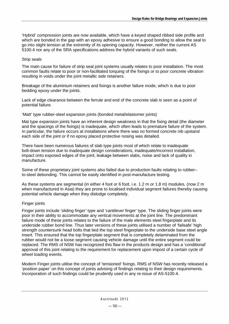
Design Rules for Bridge Bearings and Expansion Joints
A u s t r o a d s 2 0 1 2
— 102 —
‘Hybrid’ compression joints are now available, which have a keyed shaped ribbed side profile and which are bonded in the gap with an epoxy adhesive to ensure a good bonding to allow the seal to go into slight tension at the extremity of its opening capacity. However, neither the current AS 5100.4 nor any of the SRA specifications address the hybrid variants of such seals.
Strip seals
The main cause for failure of strip seal joint systems usually relates to poor installation. The most common faults relate to poor or non-facilitated torquing of the fixings or to poor concrete vibration resulting in voids under the joint metallic side retainers.
Breakage of the aluminium retainers and fixings is another failure mode, which is due to poor bedding epoxy under the joints.
Lack of edge clearance between the ferrule and end of the concrete slab is seen as a point of potential failure.
‘Matt’ type rubber-steel expansion joints (bonded metal/elastomer joints)
Mat type expansion joints have an inherent design weakness in that the fixing detail (the diameter and the spacings of the fixings) is inadequate, which often leads to premature failure of the system. In particular, the failure occurs at installations where there was no formed concrete nib upstand each side of the joint or if no epoxy placed protective nosing was detailed.
There have been numerous failures of slab type joints most of which relate to inadequate bolt-down tension due to inadequate design considerations, inadequate/incorrect installation, impact onto exposed edges of the joint, leakage between slabs, noise and lack of quality in manufacture.
Some of these proprietary joint systems also failed due to production faults relating to rubber–to-steel debonding. This cannot be easily identified in post-manufacture testing.
As these systems are segmental (in either 4 foot or 6 foot, i.e. 1.2 m or 1.8 m) modules, (now 2 m when manufactured in Asia) they are prone to localised individual segment failures thereby causing potential vehicle damage when they dislodge completely.
Finger joints
Finger joints include ‘sliding finger’ type and ‘cantilever finger’ type. The sliding finger joints were poor in their ability to accommodate any vertical movements at the joint line. The predominant failure mode of these joints relates to the failure of the male elements steel fingerplate and its underside rubber bond line. Thus later versions of these joints utilised a number of ‘failsafe’ high strength countersunk head bolts that tied the top steel fingerplate to the underside base steel angle insert. This ensured that the top fingerplate segment that is completely delaminated from the rubber would not be a loose segment causing vehicle damage until the entire segment could be replaced. The RMS of NSW has recognized this flaw in the products design and has a ‘conditional’ approval of this joint relating to the requirement for replacement upon impost of a certain cycle of wheel loading events.
Modern Finger joints utilise the concept of ‘tensioned’ fixings. RMS of NSW has recently released a ‘position paper’ on this concept of joints advising of findings relating to their design requirements. Incorporation of such findings could be prudently used in any re-issue of AS-5100.4.

Design Rules for Bridge Bearings and Expansion Joints
A u s t r o a d s 2 0 1 2
— 103 —
Poor concrete vibrating practices and poor or inadequate tensioning procedures or facilitation would be the predominant root cause of any in-service failures of such modern concept finger joints.
Modular joints
These joints are predominately a proprietary product, designed, and fabricated to in house specifications. The nature of the product is such that external expertise to analyse the design is not readily available. Location of manufacture is also of concern as in some cases fabrication is sub-contracted to outside companies. Limited usage in Australia places increasing reliance onto the overseas suppliers, and their source of fabrication.
It is recommended that improvements in future specifications are made by stipulating the need for designs to incorporate easier removability and replacement of critical damping bearings and other steel component only via access to the underside of the joint system. Such removal of these ‘replaceable’ components should be enabled without the need to cut existing welds and then re-weld in order to achieve replacement. It would be required that the steel components holding in place the replaceable damping bearing components be of bolted connection detail and not of welded connection.
Asphaltic plug joints
These joints are often referred to as ‘noiseless joints’ but can be difficult to install and have limited movement capacity. They are also prone to temperature extremes, i.e. softening and hardening.
Correct selection of the type of asphaltic binder used for the particular environmental temperature range in the location of the joint, and correct selection of aggregate grading for the particular binder grade used contribute to the joint’s performance.
Polymer nosing joints
Failure modes of these systems inevitably arise from poor bond line outcomes, predominately due to inadequate installation techniques, inadequate training of applicators, poor mixing, poor concrete substrate preparation, over-curing of primer prior to placement of polymer headers etc. In the case of urethane-based versions of header materials their placement in excessively humid conditions or dampness at the concrete surface has been the cause of material/system failure.
Design standards for bridge expansion joints
The following should be considered for inclusion in the future revision of AS 5100.4:
Revise the clauses for modular expansion joints extracting findings of RMS B316 (RTA 2005d) and/or further tests on existing installed modular joints.
Consider additions to the clauses covering finger joints to address the common use in Australia of cast-aluminium version finger joint products.
Consider reducing the maximum allowable spacing of fixings nominated in AS 5100.4 Clause 17.4 from being the current 300 mm maximum spacings to 200 mm maximum spacings.
Consider reviewing the maximum allowable ± 25% strain limitation for sealants to reflect the capabilities of newer generation products currently on the market.

Design Rules for Bridge Bearings and Expansion Joints
A u s t r o a d s 2 0 1 2
— 104 —
Current favourable trends and future directions
Significant favourable current trends in expansion joint designs and development and market demands are as follows:
The procurement of overseas manufactured products has resulted in their manufacture and testing not being under direct control of Australian road authorities. This may lead to product flaws. Thus, meaningful and qualified inspection control needs to be maintained.
The further development of an approved component list for expansion joints either by individual SRAs or by Austroads is recommended, along with suitable management controls and processes.
Any increase in the capacity and the will of SRAs to monitor product quality and to develop more accurate prescriptive specifications for expansion joints is desirable.
3.2 Miska 3.2.1 Types of Expansion Joints Manufactured Bolted-in bridge expansion joint
This is a strip seal expansion joint type (Figure 3.11), which consists of aluminium retainers and an elastomer gland. The gland comes in two shapes, being the ND gland (drape gland) and NF gland (flush gland). The drape gland is used when the joint can accommodate a zero joint gap at the maximum contraction, while the flush gland provides smaller gaps at maximum joint extension (not for use in pedestrian areas). The joint can accommodate movements of up to 125 mm. This type is approved for use by TMR.
Source: Miska website.
Figure 3.11: Miska bolted-in bridge expansion joint
Cast-in bridge expansion joint
This is another form of strip seal joint (Figure 3.12). The only difference from the bolted-in type is the design of the retainers which allow casting in to the bridge deck during initial construction. This type is approved for use by RMS, TMR and VicRoads.

Design Rules for Bridge Bearings and Expansion Joints
A u s t r o a d s 2 0 1 2
— 105 —
Source: Miska website.
Figure 3.12: Miska cast-in bridge expansion joint
Neoprene compression seal
The Miska compression seal includes three series N, NH and NC with different configurations (Figure 3.13). This joint type is used for a range of joint movement up to 72 mm. Miska FC 480 lubricant adhesive is provided to assist in the installation.
Source: Miska website.
Figure 3.13: Miska compression joint
ZealSeal 4000 expansion joint
Miska supplies a system that is made up of elastomeric ZealCrete™concrete nosing and a nitrogen blown polyethylene flexible seal epoxy fixed between the ZealCrete™ nosing. The ZealCrete™ has special properties in preventing cracks, moisture and chemical intrusion. It has resistance to high impact. The ZealSeal seal has the ability to move horizontally, vertically and transversely all at the same time. This feature makes this system a good choice for high degree skew joints. Miska recommends this joint for high volume traffic, high impact and aggressive environmental conditions.
ZealSeal 4000 can be used to repair or replace old steel plates, compression seal and broken or cracked bridge deck end expansion joints. ZealCrete™ by itself is a product used to repair broken bridge deck ends or concrete.
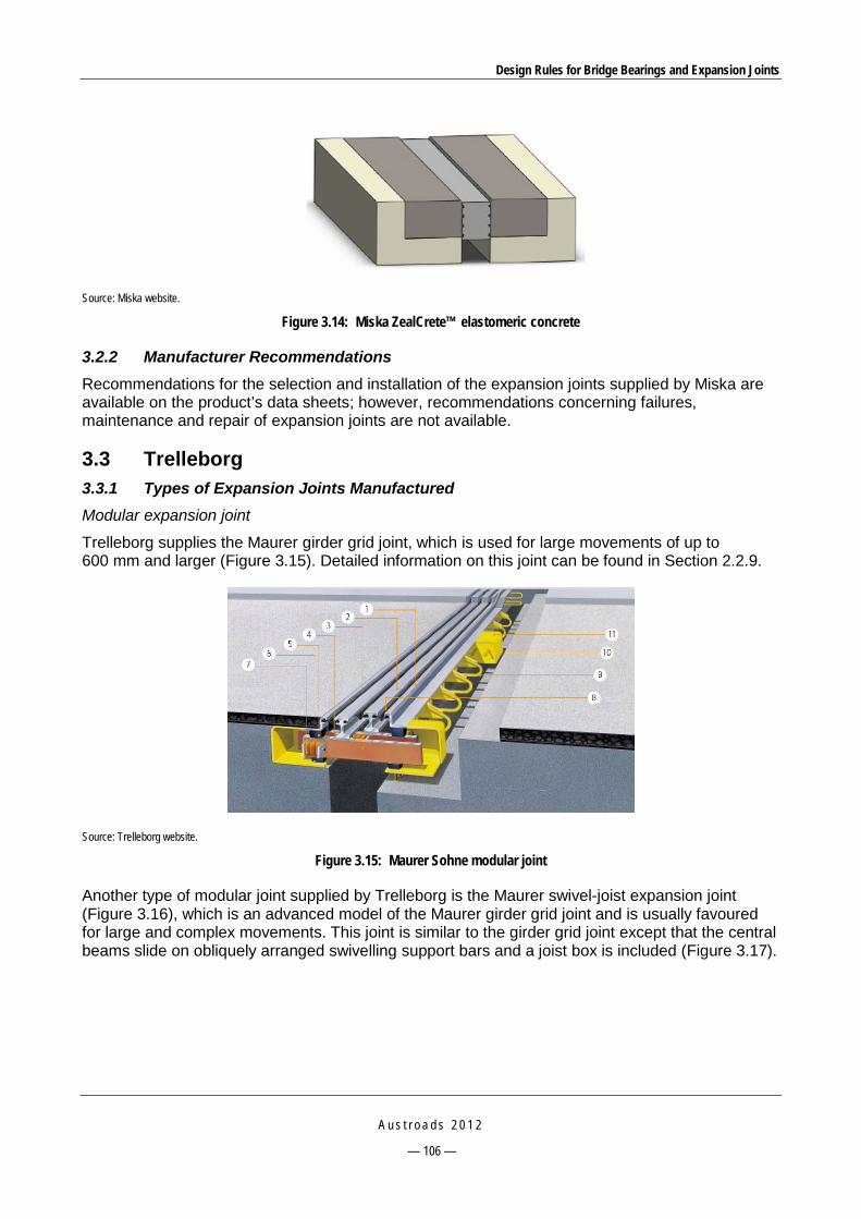
Design Rules for Bridge Bearings and Expansion Joints
A u s t r o a d s 2 0 1 2
— 106 —
Source: Miska website.
Figure 3.14: Miska ZealCrete™ elastomeric concrete
3.2.2 Manufacturer Recommendations Recommendations for the selection and installation of the expansion joints supplied by Miska are available on the product’s data sheets; however, recommendations concerning failures, maintenance and repair of expansion joints are not available.
3.3 Trelleborg 3.3.1 Types of Expansion Joints Manufactured Modular expansion joint
Trelleborg supplies the Maurer girder grid joint, which is used for large movements of up to 600 mm and larger (Figure 3.15). Detailed information on this joint can be found in Section 2.2.9.
Source: Trelleborg website.
Figure 3.15: Maurer Sohne modular joint
Another type of modular joint supplied by Trelleborg is the Maurer swivel-joist expansion joint (Figure 3.16), which is an advanced model of the Maurer girder grid joint and is usually favoured for large and complex movements. This joint is similar to the girder grid joint except that the central beams slide on obliquely arranged swivelling support bars and a joist box is included (Figure 3.17).

Design Rules for Bridge Bearings and Expansion Joints
A u s t r o a d s 2 0 1 2
— 107 —
Source: Trelleborg website.
Figure 3.16: Maurer swivel-joist expansion joint
Source: Trelleborg website.
Figure 3.17: Two-way obliquely arranged swivel support bars and joist boxes
Pourable joint seal
Trelleborg supplies the TESA PHS expansion joint system which consists of a durable impact resistant polymer header system (TESACRETE polymer concrete), a rapid–curing, pourable, two-component, self-levelling joint sealant (TESA PU) and a backer rod. This system is used for joint gaps of less than 75 mm and can provide movements of +100% to -50% of the gap width (Figure 3.18).

Design Rules for Bridge Bearings and Expansion Joints
A u s t r o a d s 2 0 1 2
— 108 —
Source: Trelleborg website.
Figure 3.18: TESA PHS System
Strip seal joints
The TESA SSA 100 expansion joint system consists of a structural alloy beam with seal retainer at each side of the joint and a drape or flush seal that can accommodate movements of up to 125 mm. The alloy beams are anchored to the structure by tensioned bolts (Figure 3.19a). A variation of this joint is TESA SSC 100, which has different design of metal retainers (Figure 3.19b).
Source: Trelleborg website.
Figure 3.19: TESA strip seal joints
Bonded metal/elastomer expansion joints
Trelleborg supplies the Transflex bridge expansion joint which consists of steel angles and a steel bridging plate embedded in a rubber elastomer (Figure 3.20). A range of models is available to accommodate movements up to 330 mm. This type of joint can be used in skew bridges and provides a substantially waterproof joint as well as a smooth, wear-resistant surface.
a – TESA SSA 100 b –TESA SSC 100

Design Rules for Bridge Bearings and Expansion Joints
A u s t r o a d s 2 0 1 2
— 109 —
Source: Trelleborg website.
Figure 3.20: Transflex expansion joints
3.3.2 Manufacturer Recommendations In a meeting at Trelleborg’s QLD factory with John Mosel and Xavier Delattre on 18 November 2010, a number of issues were identified as noted below.
Common failures
For strip seal joints, bolts may come out due to vibration. Appropriate torque should be applied to tighten the bolts in the installation. Appropriate torque should be specified by the manufacturer and supported with experimental data to prove that this torque value results in an axial tension in the anchor of 65% of ULS.
For Transflex bonded metal/elastomer joints, the common failure is the shearing of the bolts due to direct impact from vehicles if the panels are not protected by an impact-absorbing header material.
For fingerplate joints, aluminium types (CIPEC and ETIC) should only be used for movements less than 200 mm as fatigue failure of fingers is the concern. In addition, the fingers may have locking-up issues when the joint is in a fully closed position, not allowing any lateral movement.
For MBJS, inspection should be frequent (once a year) to check the replaceable components such as springs and buffers.

Design Rules for Bridge Bearings and Expansion Joints
A u s t r o a d s 2 0 1 2
— 110 —
Directions
The future generic specifications should not be limited to any overseas specifications but should be able to cover other systems approved by legitimate and internationally recognised standards or approving authorities. An example is the RMS B316 specification for MBJS is based on American standards, so it ruled out all the products designed according to European standards which have a longer history.
It is recommended that Eurocode TL/Tp FU 92 be included for MBJS.
In an email from Xavier Delattre on 4 February 2011, recommendations for revising AS 5100.4 were also provided:
The inclusion of other small expansion joint systems such as compression seals, polyurethane concrete header joints, Transflex, finger joints and cast-in strip seal systems should be considered.
The production of different rubber compounds for each state is extremely difficult to achieve and to manage. In turn, these properties could be included in AS 5100.4. The seal material and its specification should also be reviewed. The neoprene specified is extremely difficult to manufacture, and the benefit of neoprene over natural rubber is also questionable. EPDM (ethylene propylene diene monomer) is recommended as an alternative material.
Cast-in aluminium joints: the cost/benefit of stainless steel anchors over hot dip galvanised ones is questioned; the need for joints in the aluminium extrusion to only occur at the road centre line or lane line does not appear to offer increased durability, but it makes manufacturing and installation more complicated and expensive. Again, it is a cost/benefit exercise; the tensioning of anchors is the most critical factor in terms of durability of the joint in service.
Most failures of the aluminium strip seal systems installed to date are due to the loosening of the anchor bolts. Consequently, the existing specifications should address the correct number of anchors to be used and the correct torque to be applied to them to prevent loosening under fatigue. In fact, some of the installed systems specifying a ‘snug and turn’ method would work well under the AS 5100.4 required 500 kN/m per side of joint. The key to this is to translate a given torque into an actual axial hold-down force in the anchor. This can be calculated, but the nut/thread friction factor ’k’ is critical. This ’k’ factor will be particular to the finish on the thread of the anchors, and therefore it should be verified by lab testing.
Breakages of bolts used in bridge deck expansion joints anchored in concrete have been experienced on some RMS bridges. Fatigue and vibration loosening were found to be the main causes of failure. It was recognised that applying adequate preload to the bolts (or fasteners) is critical for long-term performance of the joints, and is the best way to prevent fatigue and vibration loosening.
Possible text that could be added to specifications in the future was suggested:
Further to the requirements of AS 5100.4 clause 17.4, the supplier of the joint shall provide calculations to show the relationship between the applied torque and the resulting axial hold-down force provided by the anchors. The k factor used in these calculations shall be determined by testing a batch of 10 anchors in a NATA laboratory approved to conduct these tests. The calculations shall be completed or verified by an engineer eligible to the Chartered status of the Institute of Engineers Australia. A minimum of M20 grade 8.8 anchors at 200 mm spacings each side of the joint shall be used.
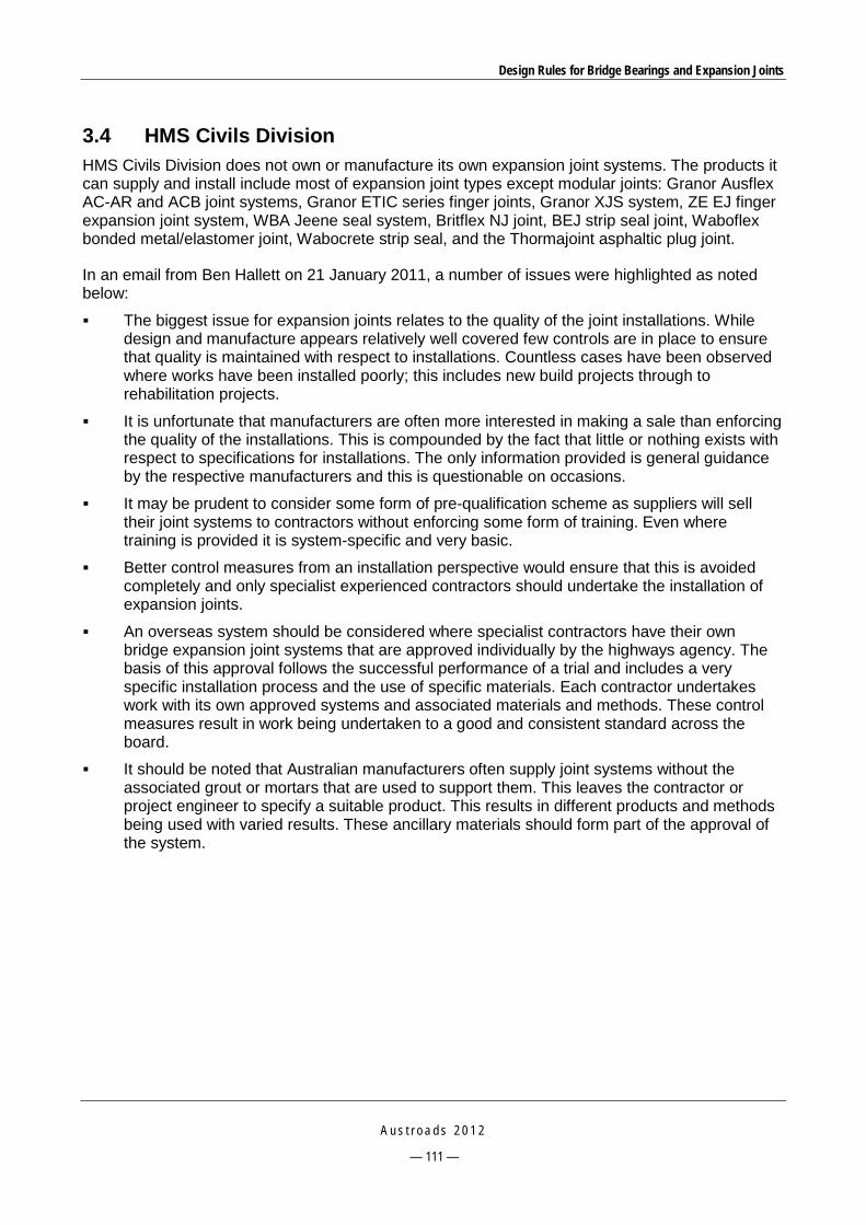
Design Rules for Bridge Bearings and Expansion Joints
A u s t r o a d s 2 0 1 2
— 111 —
3.4 HMS Civils Division HMS Civils Division does not own or manufacture its own expansion joint systems. The products it can supply and install include most of expansion joint types except modular joints: Granor Ausflex AC-AR and ACB joint systems, Granor ETIC series finger joints, Granor XJS system, ZE EJ finger expansion joint system, WBA Jeene seal system, Britflex NJ joint, BEJ strip seal joint, Waboflex bonded metal/elastomer joint, Wabocrete strip seal, and the Thormajoint asphaltic plug joint.
In an email from Ben Hallett on 21 January 2011, a number of issues were highlighted as noted below:
The biggest issue for expansion joints relates to the quality of the joint installations. While design and manufacture appears relatively well covered few controls are in place to ensure that quality is maintained with respect to installations. Countless cases have been observed where works have been installed poorly; this includes new build projects through to rehabilitation projects.
It is unfortunate that manufacturers are often more interested in making a sale than enforcing the quality of the installations. This is compounded by the fact that little or nothing exists with respect to specifications for installations. The only information provided is general guidance by the respective manufacturers and this is questionable on occasions.
It may be prudent to consider some form of pre-qualification scheme as suppliers will sell their joint systems to contractors without enforcing some form of training. Even where training is provided it is system-specific and very basic.
Better control measures from an installation perspective would ensure that this is avoided completely and only specialist experienced contractors should undertake the installation of expansion joints.
An overseas system should be considered where specialist contractors have their own bridge expansion joint systems that are approved individually by the highways agency. The basis of this approval follows the successful performance of a trial and includes a very specific installation process and the use of specific materials. Each contractor undertakes work with its own approved systems and associated materials and methods. These control measures result in work being undertaken to a good and consistent standard across the board.
It should be noted that Australian manufacturers often supply joint systems without the associated grout or mortars that are used to support them. This leaves the contractor or project engineer to specify a suitable product. This results in different products and methods being used with varied results. These ancillary materials should form part of the approval of the system.

Design Rules for Bridge Bearings and Expansion Joints
A u s t r o a d s 2 0 1 2
— 112 —
4 STATE ROAD AUTHORITY EXPERIENCES WITH BRIDGE EXPANSION JOINTS
4.1 Popular Types of Bridge Expansion Joints Used Nationwide There are a number of expansion joint types being used in Australia. Their usage depends on various factors such as bridge type, bridge configuration and required movements. In general, the most common types of expansion joints are:
fixed joints
sliding plate joints
asphaltic plug joints
pour sealant joints
compression seal joints
strip seal joints
moulded rubber joints
bonded metal/elastomer expansion joints
fingerplate joints
modular joints.
4.1.1 Fixed Joint The fixed joint is a simple type of joint. It is basically fixed but may allow very small movements of 1 or 2 mm. It may use several types of material: mortar, compressible filler, sealant or compressible sheet. This type of joint is used mostly in prestressed concrete deck unit bridges (Figure 4.1).
Source: QMR (2004).
Figure 4.1: Some types of fixed joints used in Queensland
4.1.2 Sliding Steel Plate Sliding steel plate joints were used in the past throughout Australia for the movement range of 50 mm to 100 mm (Figure 4.2). They are no longer been used under road traffic conditions as they

Design Rules for Bridge Bearings and Expansion Joints
A u s t r o a d s 2 0 1 2
— 113 —
do not conform to AS 5100.4 in regards to watertightness and sealing against dirt ingress, and can generate excessive noise and problems in service.
Source: RTA (2008b).
Figure 4.2: Sliding steel plate joint
4.1.3 Asphaltic Plug Joints This joint type was used in short span bridges having expansion movement of less than 50 mm (Figure 4.3). They are no longer used in new construction.
Source: VicRoads (2007).
Figure 4.3: Asphaltic plug joint
4.1.4 Pour Sealant Joints This joint type is used widely by RMS and TMR for short bridges with a movement range of up to about 20 mm (Figure 4.4 and Figure 4.5) using hot-poured or cold-applied sealants.

Design Rules for Bridge Bearings and Expansion Joints
A u s t r o a d s 2 0 1 2
— 114 —
Source: QMR (2004).
Figure 4.4: Pourable sealant joint used in Queensland
Source: RMS standard drawing B035, 2007.
Figure 4.5: Sealant joints used in NSW
For the sealant, RMS uses four types: self-levelling trafficable, self-levelling non-trafficable, non-sag trafficable and non-sag non-trafficable sealants depending on the location of the sealant and the surrounding material.
4.1.5 Compression Seal Joints Compression seal joints have been used widely in Australia (Figure 4.6 and Figure 4.7). They have a variety of sizes and configurations and may accommodate for movements of 5-60 mm.
Source: QMR (2004).
Figure 4.6: Compression seal joint using steel angles
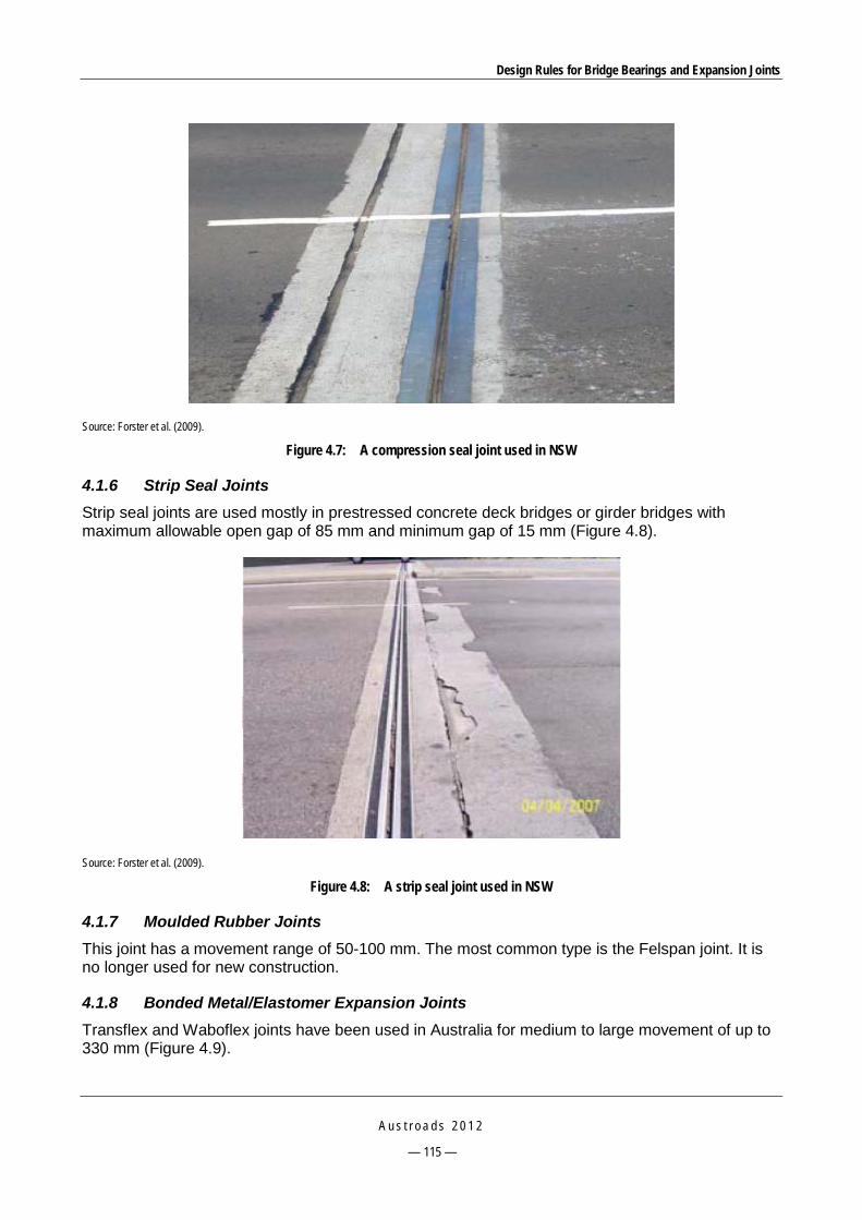
Design Rules for Bridge Bearings and Expansion Joints
A u s t r o a d s 2 0 1 2
— 115 —
Source: Forster et al. (2009).
Figure 4.7: A compression seal joint used in NSW
4.1.6 Strip Seal Joints Strip seal joints are used mostly in prestressed concrete deck bridges or girder bridges with maximum allowable open gap of 85 mm and minimum gap of 15 mm (Figure 4.8).
Source: Forster et al. (2009).
Figure 4.8: A strip seal joint used in NSW
4.1.7 Moulded Rubber Joints This joint has a movement range of 50-100 mm. The most common type is the Felspan joint. It is no longer used for new construction.
4.1.8 Bonded Metal/Elastomer Expansion Joints Transflex and Waboflex joints have been used in Australia for medium to large movement of up to 330 mm (Figure 4.9).
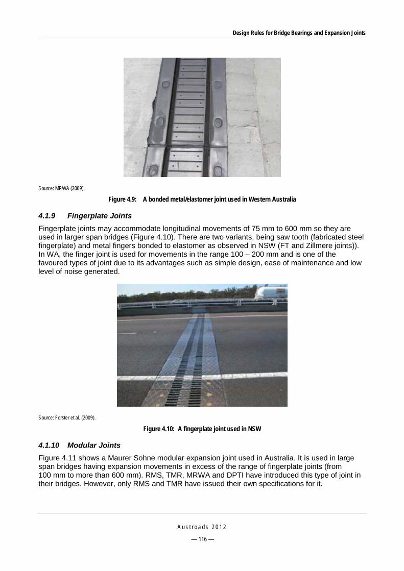
Design Rules for Bridge Bearings and Expansion Joints
A u s t r o a d s 2 0 1 2
— 116 —
Source: MRWA (2009).
Figure 4.9: A bonded metal/elastomer joint used in Western Australia
4.1.9 Fingerplate Joints Fingerplate joints may accommodate longitudinal movements of 75 mm to 600 mm so they are used in larger span bridges (Figure 4.10). There are two variants, being saw tooth (fabricated steel fingerplate) and metal fingers bonded to elastomer as observed in NSW (FT and Zillmere joints)). In WA, the finger joint is used for movements in the range 100 – 200 mm and is one of the favoured types of joint due to its advantages such as simple design, ease of maintenance and low level of noise generated.
Source: Forster et al. (2009).
Figure 4.10: A fingerplate joint used in NSW
4.1.10 Modular Joints Figure 4.11 shows a Maurer Sohne modular expansion joint used in Australia. It is used in large span bridges having expansion movements in excess of the range of fingerplate joints (from 100 mm to more than 600 mm). RMS, TMR, MRWA and DPTI have introduced this type of joint in their bridges. However, only RMS and TMR have issued their own specifications for it.

Design Rules for Bridge Bearings and Expansion Joints
A u s t r o a d s 2 0 1 2
— 117 —
1 Edge beam 2 Centre beam 3 Support bar 4 Sliding plate 5 Sliding spring 6 Sliding bearing 7 Control spring 8 Strip seal 9 Carriageway anchor 10 Anchor stud 11 Support box. Source: Trelleborg website.
Figure 4.11: Maurer Sohne modular expansion joint
4.2 Roads and Maritime Services, New South Wales (RMS) 4.2.1 Specifications RMS has a number of quality assurance (QA) specifications for the design, manufacture, supply and installation of bridge expansion joints (Table 4.1).
Table 4.1: Specifications for expansion joints in RMS
Code Name Date of issue
B310 Compression seal expansion joints 2006
B312 Cold applied elastomeric joint sealants 2006
B315 Elastomeric strip seal expansion joints 2007
B316 Modular bridge expansion joints 2005
B318 Bonded metal/elastomer expansion joints 2008
B319 Proprietary aluminium expansion joints 2008 The specifications are summarised below.
B310 specifies the requirements for the design, supply and installation of preformed elastomeric compression seals of the open-cell type and the adhesive lubricant used for installation. Detailed material properties of the seal are specified along with allowable tolerances for the seal

Design Rules for Bridge Bearings and Expansion Joints
A u s t r o a d s 2 0 1 2
— 118 —
cross-section and requirements for a recovery test. For the adhesive lubricant, it also sets out the requirements for the properties. Both seal and lubricant are required to be tested by ASTM test methods.
B312 sets out the requirements for the properties and performance of rapid curing, cold applied, elastomeric sealants for small movement bridge deck joints. There are four types of sealants: self-levelling trafficable, self-levelling non-trafficable, non-sag trafficable and non-sag non-trafficable sealants; and three different applications: type A for sawn joints in asphalt, type B for joints in concrete underneath asphalt, and type C for joints in concrete away from asphalt. There are two hold points for delivery of the sealant to the site and installation. The guarantee period is five years minimum.
B315 covers the requirements for the supply and installation of preformed elastomeric strip seal expansion joints, including the metal seal retainers and their anchorages. Detailed requirements for the elastomer material, design of retainers and anchorages as well as installation tolerances are specified. The joint will be under a minimum warranty period of five years from the date of installation.
B316 covers the requirements for the design, fabrication, testing, supply and installation of modular bridge expansion joints including both single and multiple support bar systems. It is noted that only RMS and TMR have a technical specification for this modern joint type. The required design service life varies for different components, which is 15 years for compression and control springs and support bearings, 20 years for joint seals, and 100 years for centre beams, support bars, support boxes and welded attachments. The provisions for replaceable components are specified that minimise impact to traffic during replacement. The following annexures are also included:
Annexure B316/A: specific project requirements: joint openings, horizontal forces, additional requirements for skewed joints
Annexure B316/B: payment and resolution of nonconformities
Annexure B316/C: Schedules of hold and witness points and identified records: 6 hold points, 5 witness points, and 14 documents
Annexure B316/D: Planning documents, e.g. quality management, procedures and fabrication program
Annexure 316/E: Design methodology that sets out requirements on limit state checks, such as required yield strength of structural steel members, tensile strength of connections, fatigue limit state, strength limit state and ULS checks. Detailed calculation methods for structural analysis and limit state design of all joint components are also included.
Annexure B316/L: Outlines test procedure for experimental modal analysis to determine the mode shapes, natural frequencies, modal damping and dynamic amplification factors. The data can be used to calibrate any dynamic FE model developed to assist the fatigue design of project-specific modular joints.
B318 specifies the requirements for the supply and installation of bonded metal/elastomer expansion joints. In general the design requirements conform to AS 5100.4. Detailed provisions for anchors, elastomer material, and corrosion protection are included. Installation procedures are also required to be submitted to RMS before installation of the joint. The guarantee period is also five years.

Design Rules for Bridge Bearings and Expansion Joints
A u s t r o a d s 2 0 1 2
— 119 —
B319 sets out the provisions for the supply and installation of proprietary aluminium bridge expansion joints. Only brand names listed in RMS’s approved list in BTD 2008/11 (RTA 2010b) shall be used.
4.2.2 Design and Construction RMS BTD2008/10 (RTA 2008b) regarding bridge deck joint selection, design, installation and maintenance was issued based on the results of field inspections of RMS bridges carried out since 1995/1996. The aim of this BTD is to provide background information on bridge deck joints used in RMS bridges and to specify a comprehensive approach to joint selection, design, installation, assessment, maintenance and rehabilitation, taking into account the importance of this component on the bridge structure that may affect maintenance or replacement cost and performance of other components.
According to this BTD, RMS has discontinued the use of cork or hose filled, hot poured sealant, moulded elastomer with strip seal, open gap without protection angles, semi-rigid epoxy and sliding steel plate joints. The reasons are summarised below:
Cork or hose filled joints are not suitable for trafficable surfaces as they will displace under vehicle loading and are not watertight. They are used only for footpath due to their low cost and ease of installation. Existing joints may be replaced by cold applied sealant joints if damaged.
Hot poured sealant becomes soft under hot weather and stiff under cold weather. If damaged, this joint may be replaced by a cold applied sealant joint.
Moulded elastomer with strip seal was discontinued since the anchorage is not adequate and the elastomeric moulding wears excessively around the retainers. The failure develops rapidly after initiation. If failed, this joint may be replaced by a strip seal, a bonded metal elastomer or a finger joint.
Open gap without protection angles does not comply with AS 5100.4 as metal armouring is required to protect the concrete deck edges. If damaged, this joint may be replaced by a cold sealant, compression seal or a strip seal.
Sliding steel plate is not watertight and has a high level of noise. In addition, the plate becomes loose over time so it requires frequent tightening of the bolts. If failed, this joint may be replaced by a compression seal, strip seal or finger joints.
Semi-rigid epoxy is too stiff at low temperatures and delaminated from the concrete under tension or at high temperatures. If damaged, an asphaltic plug, a cold applied sealant or a compression seal may be replaced.
In addition, four types of joints are of limited use and only allowed following site-specific studies. They are asphaltic plug, bonded metal/elastomer, metal fingers bonded to elastomer and open gap with protection angles, as follows:
Bonded metal elastomer is only used with caution due to its high replacement cost and variable field performance.
The reason why the use of metal fingers bonded to elastomer is limited rests on its weak debonding metal male plate to baseplate.
Open gap with protection angles conforms to AS 5100.4 only when used with troughs for drainage under the deck or along the top of headstock.
The use of asphaltic plug expansion joints has been restricted even though they are easy to install and repair and provide a smooth, quiet and seamless road surface for traffic. These
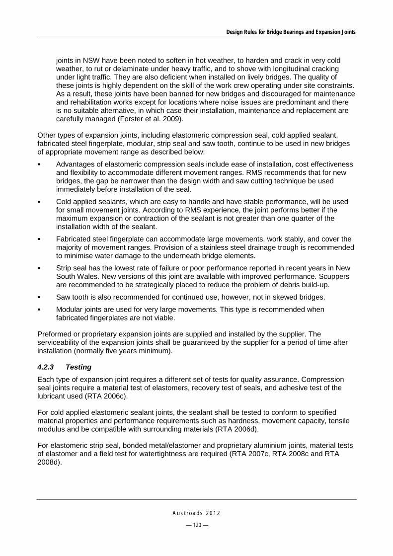
Design Rules for Bridge Bearings and Expansion Joints
A u s t r o a d s 2 0 1 2
— 120 —
joints in NSW have been noted to soften in hot weather, to harden and crack in very cold weather, to rut or delaminate under heavy traffic, and to shove with longitudinal cracking under light traffic. They are also deficient when installed on lively bridges. The quality of these joints is highly dependent on the skill of the work crew operating under site constraints. As a result, these joints have been banned for new bridges and discouraged for maintenance and rehabilitation works except for locations where noise issues are predominant and there is no suitable alternative, in which case their installation, maintenance and replacement are carefully managed (Forster et al. 2009).
Other types of expansion joints, including elastomeric compression seal, cold applied sealant, fabricated steel fingerplate, modular, strip seal and saw tooth, continue to be used in new bridges of appropriate movement range as described below:
Advantages of elastomeric compression seals include ease of installation, cost effectiveness and flexibility to accommodate different movement ranges. RMS recommends that for new bridges, the gap be narrower than the design width and saw cutting technique be used immediately before installation of the seal.
Cold applied sealants, which are easy to handle and have stable performance, will be used for small movement joints. According to RMS experience, the joint performs better if the maximum expansion or contraction of the sealant is not greater than one quarter of the installation width of the sealant.
Fabricated steel fingerplate can accommodate large movements, work stably, and cover the majority of movement ranges. Provision of a stainless steel drainage trough is recommended to minimise water damage to the underneath bridge elements.
Strip seal has the lowest rate of failure or poor performance reported in recent years in New South Wales. New versions of this joint are available with improved performance. Scuppers are recommended to be strategically placed to reduce the problem of debris build-up.
Saw tooth is also recommended for continued use, however, not in skewed bridges.
Modular joints are used for very large movements. This type is recommended when fabricated fingerplates are not viable.
Preformed or proprietary expansion joints are supplied and installed by the supplier. The serviceability of the expansion joints shall be guaranteed by the supplier for a period of time after installation (normally five years minimum).
4.2.3 Testing Each type of expansion joint requires a different set of tests for quality assurance. Compression seal joints require a material test of elastomers, recovery test of seals, and adhesive test of the lubricant used (RTA 2006c).
For cold applied elastomeric sealant joints, the sealant shall be tested to conform to specified material properties and performance requirements such as hardness, movement capacity, tensile modulus and be compatible with surrounding materials (RTA 2006d).
For elastomeric strip seal, bonded metal/elastomer and proprietary aluminium joints, material tests of elastomer and a field test for watertightness are required (RTA 2007c, RTA 2008c and RTA 2008d).
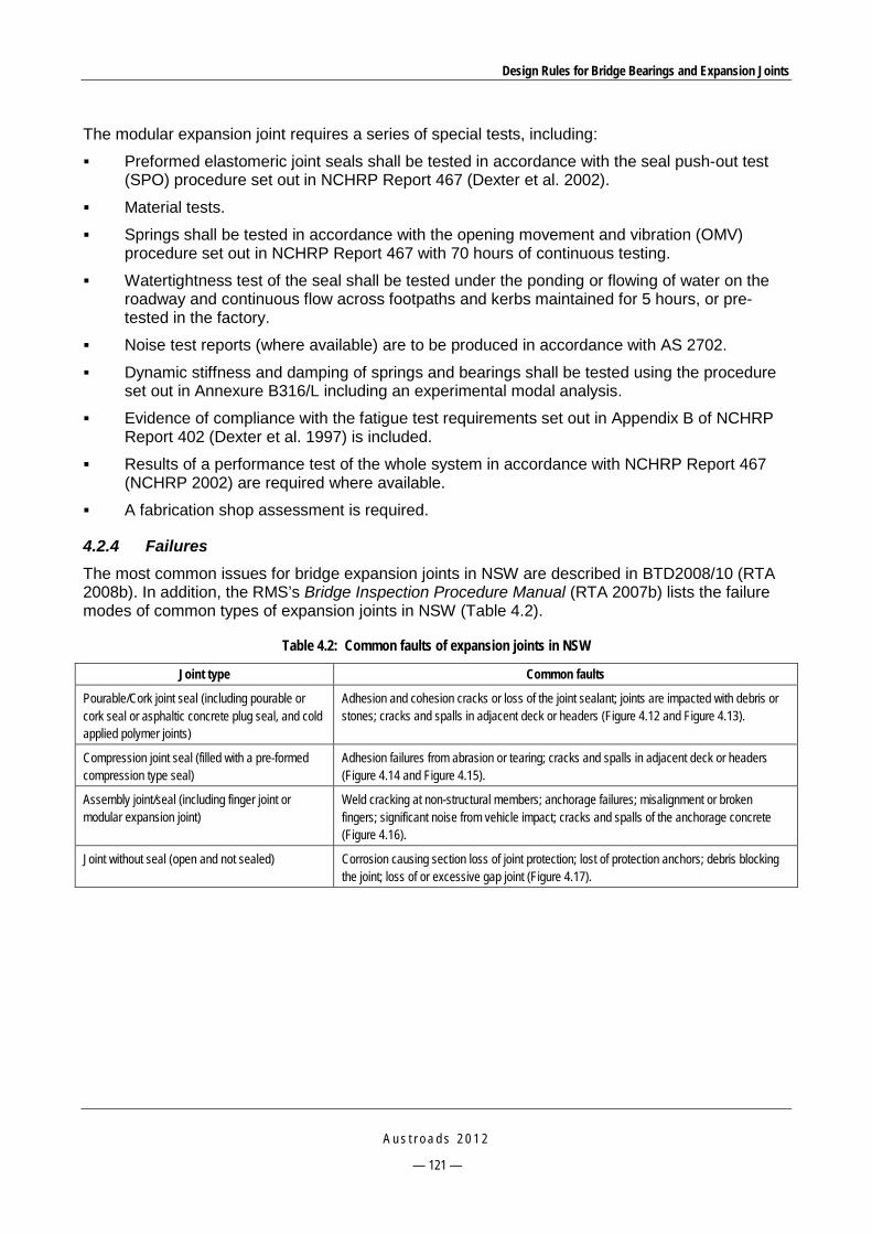
Design Rules for Bridge Bearings and Expansion Joints
A u s t r o a d s 2 0 1 2
— 121 —
The modular expansion joint requires a series of special tests, including:
Preformed elastomeric joint seals shall be tested in accordance with the seal push-out test (SPO) procedure set out in NCHRP Report 467 (Dexter et al. 2002).
Material tests.
Springs shall be tested in accordance with the opening movement and vibration (OMV) procedure set out in NCHRP Report 467 with 70 hours of continuous testing.
Watertightness test of the seal shall be tested under the ponding or flowing of water on the roadway and continuous flow across footpaths and kerbs maintained for 5 hours, or pre-tested in the factory.
Noise test reports (where available) are to be produced in accordance with AS 2702.
Dynamic stiffness and damping of springs and bearings shall be tested using the procedure set out in Annexure B316/L including an experimental modal analysis.
Evidence of compliance with the fatigue test requirements set out in Appendix B of NCHRP Report 402 (Dexter et al. 1997) is included.
Results of a performance test of the whole system in accordance with NCHRP Report 467 (NCHRP 2002) are required where available.
A fabrication shop assessment is required.
4.2.4 Failures The most common issues for bridge expansion joints in NSW are described in BTD2008/10 (RTA 2008b). In addition, the RMS’s Bridge Inspection Procedure Manual (RTA 2007b) lists the failure modes of common types of expansion joints in NSW (Table 4.2).
Table 4.2: Common faults of expansion joints in NSW
Joint type Common faults
Pourable/Cork joint seal (including pourable or cork seal or asphaltic concrete plug seal, and cold applied polymer joints)
Adhesion and cohesion cracks or loss of the joint sealant; joints are impacted with debris or stones; cracks and spalls in adjacent deck or headers (Figure 4.12 and Figure 4.13).
Compression joint seal (filled with a pre-formed compression type seal)
Adhesion failures from abrasion or tearing; cracks and spalls in adjacent deck or headers (Figure 4.14 and Figure 4.15).
Assembly joint/seal (including finger joint or modular expansion joint)
Weld cracking at non-structural members; anchorage failures; misalignment or broken fingers; significant noise from vehicle impact; cracks and spalls of the anchorage concrete (Figure 4.16).
Joint without seal (open and not sealed) Corrosion causing section loss of joint protection; lost of protection anchors; debris blocking the joint; loss of or excessive gap joint (Figure 4.17).
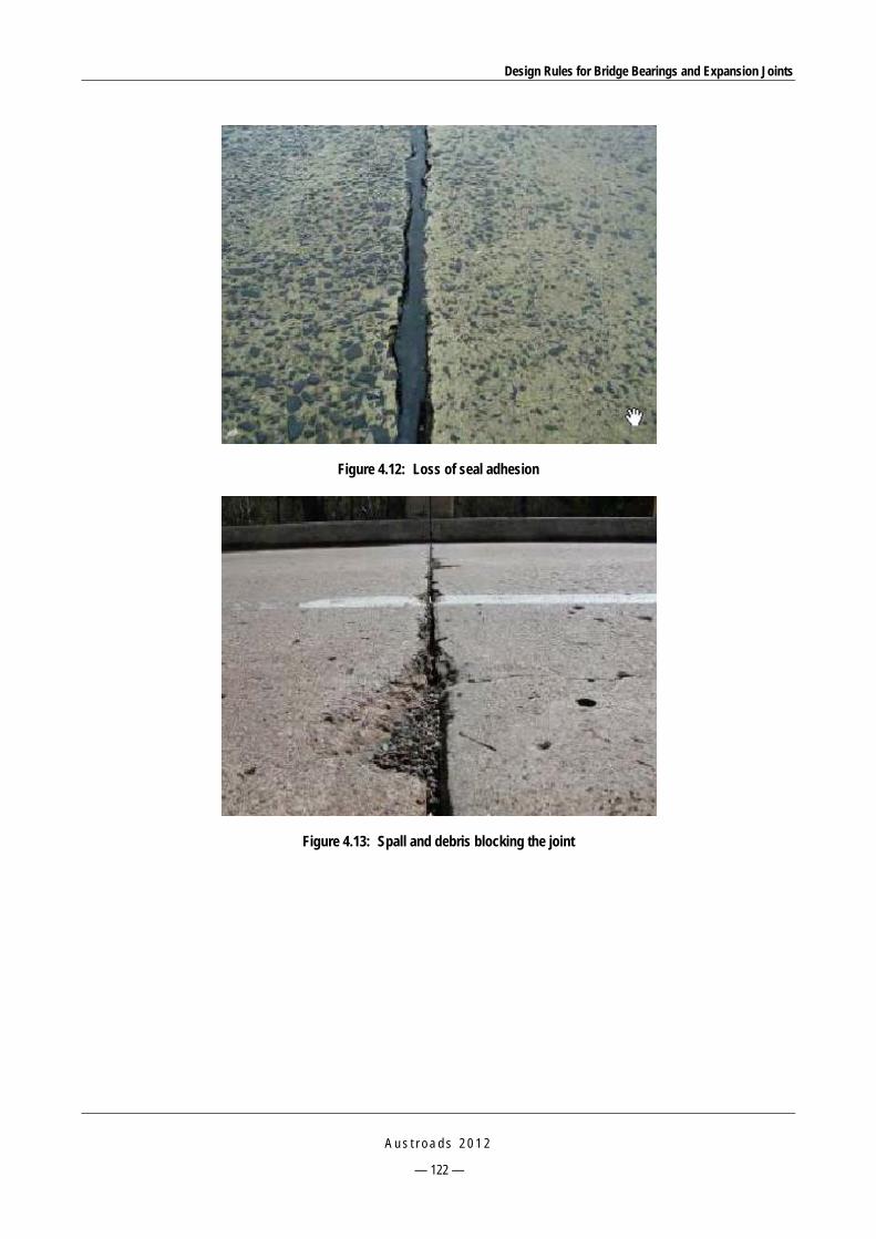
Design Rules for Bridge Bearings and Expansion Joints
A u s t r o a d s 2 0 1 2
— 122 —
Figure 4.12: Loss of seal adhesion
Figure 4.13: Spall and debris blocking the joint

Design Rules for Bridge Bearings and Expansion Joints
A u s t r o a d s 2 0 1 2
— 123 —
Figure 4.14: Loss of adhesion on sides of the compression seal
Figure 4.15: Spall and loose nut of a compression joint

Design Rules for Bridge Bearings and Expansion Joints
A u s t r o a d s 2 0 1 2
— 124 —
Figure 4.16: Broken anchor bolts and assembly breaking loose
Figure 4.17: Joint blocked with debris and spalls appearing at joint edges
4.2.5 Repair and Maintenance
As noted in Section 4.2.4, RMS has a Bridge Inspection Procedure Manual (RTA 2007b), part of which is for expansion joint inspection. For each type of expansion joint, four condition states are given with clear descriptions and illustrative photos. The manual is a very useful resource for condition management of bridge expansion joints.

Design Rules for Bridge Bearings and Expansion Joints
A u s t r o a d s 2 0 1 2
— 125 —
BTD2008/10 (RTA 2008b) Section 6 provides brief guidelines on monitoring, maintenance and rehabilitation for the most common joint types such as asphaltic plug, elastomeric compression seal, sealant, fingerplate, modular and strip seal.
4.3 Roads Corporation, Victoria (VicRoads) 4.3.1 Specifications VicRoads is currently using the following technical notes and standards for the design and installation of bridge deck joints:
Bridge Technical Note BTN1999/002 – Design of deck joints for road bridges (VicRoads 2010)
Section 660 of VicRoads Standard Specification – Deck expansion joints (VicRoads 2006)
Bridge Technical Note BTN2002/001 – Reinforcement of deck joints (VicRoads 2005c).
In general, most of the design requirements specified in BTN1999/002 conform to AS 5100.4. Specifically, the requirements for noise, vibration, sealing, covering, corrosion resistance and accessibility are in accordance with AS 5100.4 as are the provisions for design loads, fatigue, movements and gap width, anchorage of desk joints, and drainage.
For maintenance, it is specified that the serviceability of the joint be guaranteed by the supplier for a minimum period of 10 years after installation. It is also recommended that the joint sealant type be used on short span bridges having a range of movement of less than 20 mm or limited to ±25% of the installation width.
VicRoads specified lists of approved deck-joint suppliers and types of joints in BTN1999/002, however, are out-of-date. Currently VicRoads does not maintain these lists nor does it have an evaluation or approval process. Normally joints that comply with AS 5100 design/material requirements and VicRoads specifications are acceptable provided that they have a satisfactory history of performance. New products that comply with the design and specification requirements may also be considered for use. Proposals in relation to products of this type are normally submitted by the contractor to the Superintendent who may, in-turn, seek advice about their use from the Structures Section. For wholly new items, this process may include an appraisal of information from the supplier. Once a product has been accepted on this basis, subsequent use on other projects is a simpler process (Henry Luczak’s email, 10 March 2010).
VicRoads standard specification Section 660 (VicRoads 2006) sets out the requirements for the supply and installation of deck expansion joints for bridges. Beside the standard requirements, the following tolerances on the installation of the joint are specified:
joint gap ±3 mm
top surface of joint to be within 5 mm of a 2.5 m straight edge
deviation from plan alignment is 5 mm maximum.
In addition, BTN2002/001 sets out the requirements for the design of anchorage reinforcement and transverse reinforcement in the concrete nosings adjacent to the joint to prevent deterioration of the concrete in these areas. Specifically it requires that at least three No. 16 bars be used on each side of the joint as shown in Figure 4.18.
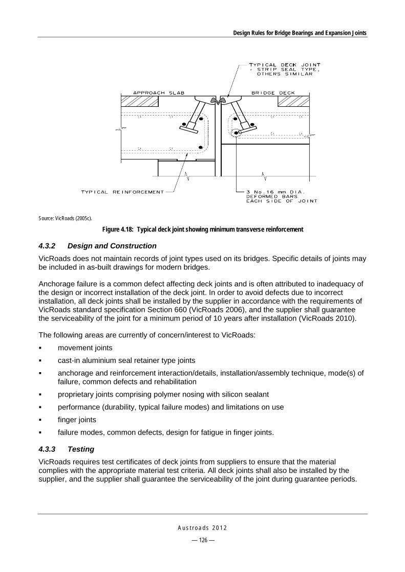
Design Rules for Bridge Bearings and Expansion Joints
A u s t r o a d s 2 0 1 2
— 126 —
Source: VicRoads (2005c).
Figure 4.18: Typical deck joint showing minimum transverse reinforcement
4.3.2 Design and Construction VicRoads does not maintain records of joint types used on its bridges. Specific details of joints may be included in as-built drawings for modern bridges.
Anchorage failure is a common defect affecting deck joints and is often attributed to inadequacy of the design or incorrect installation of the deck joint. In order to avoid defects due to incorrect installation, all deck joints shall be installed by the supplier in accordance with the requirements of VicRoads standard specification Section 660 (VicRoads 2006), and the supplier shall guarantee the serviceability of the joint for a minimum period of 10 years after installation (VicRoads 2010).
The following areas are currently of concern/interest to VicRoads:
movement joints
cast-in aluminium seal retainer type joints
anchorage and reinforcement interaction/details, installation/assembly technique, mode(s) of failure, common defects and rehabilitation
proprietary joints comprising polymer nosing with silicon sealant
performance (durability, typical failure modes) and limitations on use
finger joints
failure modes, common defects, design for fatigue in finger joints.
4.3.3 Testing VicRoads requires test certificates of deck joints from suppliers to ensure that the material complies with the appropriate material test criteria. All deck joints shall also be installed by the supplier, and the supplier shall guarantee the serviceability of the joint during guarantee periods.

Design Rules for Bridge Bearings and Expansion Joints
A u s t r o a d s 2 0 1 2
— 127 —
4.3.4 Failures The following failure modes (Table 4.3) are extracted from VicRoads Bridge inspection manual (VicRoad 2007) and the database provided by VicRoads Network and Asset Planning (email from Mahes T Maheswaran on 21 February 2011).
Table 4.3: Common failure modes of expansion joints in Victoria
Joint type Common faults
Pourable joint seal 30O (pourable joint sealant or asphalts)
Adhesion and cohesion cracking; spalling of adjacent deck or asphalt; joint failed due to moisture penetration; partial lost of sealant; broken bitumen/cork filler; ripped out in chunks by traffic; leaking
Compression joint seal 31O (preformed compression type seals: Wabo Hercules seals)
Loss of adhesion; seals deteriorated, dislodged or missing due to traffic impact; spalling of adjacent deck or asphalt; damaged steel armouring; leaking
Assembly joint seal 32O (Transflex, Felspan, Wabo Maurer gland seals, Cipec and Firmsec)
Glands split or pulled out of the housings; peeled rubber; loose or failed anchorage; cracked concrete nosings; rutted or cracked asphalt nosings; leaking; noisy
Open expansion joint 33S (with steel edge armouring) Corrosion of steel; loose armouring due to traffic impact; debris jam in the joint; crack or spalling of concrete deck due to loose or broken anchorages of the armouring; the deck joint closed up due to trapped dirt and grit
Sliding joint 34S (sliding plate, steel finger joints, PSC FT, Cipec and Firmsec)
Corroded steel plates; failed anchorage bolts; cracking and broken up asphalt; broken steel fingers due to excessive movement or rotations; raised fingers well above the mating fingers; failed or missing catch drains or membranes
In addition to the above failures, early tearing failures of neoprene glands in extruded aluminium alloy rail joints due to mechanical damage have been observed (Henry Luczak’s email, 8 February 2011).
4.3.5 Repair and Maintenance There was no information found or provided.
4.4 Department of Transport and Main Roads, Queensland (TMR) 4.4.1 Specifications TMR has a number of specifications and technical standards for the design, supply and installation of bridge expansion joints. They include:
MRTS82: Bridge deck expansion joints (TMR 2009c)
MRTS90: Modular bridge expansion joints (TMR 2009d)
Design criteria for bridges and other structures, Section 7.6.2.21 (TMR 2009e).
4.4.2 Design and Construction Some types of expansion joints have been discontinued in TMR (TMR 2009e):
bonded steel/rubber type joints
open joints
MultiflexTM joints (due to excessive noise generated)
flush seals used for alu-strip expansion joints with a skew greater than 25 degrees.

Design Rules for Bridge Bearings and Expansion Joints
A u s t r o a d s 2 0 1 2
— 128 —
Finger joint and modular joint types are favoured for future use. However, there is a specification only for modular joints. There is a need for a specification for the design and installation of finger joints.
4.4.3 Testing For expansion joints using elastomer seals, evidence is required that the elastomer used in the manufacture of the joint seals has been tested in accordance with Table 5.2.2 of MRTS82 (TMR 2009c).
For modular expansion joints, similar to RMS B316, a series of tests are required, including:
Preformed elastomeric joint seals shall be tested in accordance with the seal push-out test procedure set out in NCHRP Report 467 (Dexter et al. 2002).
Elastomer used in the manufacture of the joint seals shall be tested in accordance with Table 9.7 of MRTS90 (TMR 2009d).
Test certificates for steel components in accordance with MRTS78 Fabrication of Structural Steelwork shall be provided.
Test reports showing conformance of the lubricant with the requirements of penetration and evaporation tests shall be provided.
Springs shall be tested in accordance with the opening movement and vibration (OMV) procedure set out in NCHRP Report 467 (Dexter et al. 2002) with 70 hours of continuous testing.
Watertightness test of the seal shall be tested under a 25 mm depth of water on the roadway and continuous flow across footpaths and kerbs maintained for 5 hours, or pre-tested in the factory.
Noise test report (where available) in accordance with AS 2702.
Dynamic stiffness and damping of springs and bearings shall be tested by the testing procedure set out in Appendix B of MTRS90 (TMR 2009d).
Evidence of compliance with the fatigue test requirements set out in Appendix B of NCHRP Report 402 (Dexter et al. 1997).
Results of the performance test of the whole system in accordance with NCHRP Report 467 (Dexter et al. 2002) must be provided where available.
A fabrication shop assessment shall also be required.
4.4.4 Failures Table 4.4 outlines the common failure modes of expansion joints in Queensland as observed in recent inspections.
Table 4.4: Common failure modes of expansion joints in Queensland
Joint type Common faults
Pourable joint seals 10O (joints filled with pourable joint sealant or asphalts, including buried expansion joints)
Adhesion and cohesion cracking; spalling of adjacent deck or asphalt; joint failed due to moisture penetration; partial lost of sealant; bitumen/cork filler broken or ripped out in chunks by traffic; cracked nosings; sections delaminated from the deck; fretting or loosing of surrounding asphalt.
Design Rules for Bridge Bearings and Expansion Joints
A u s t r o a d s 2 0 1 2
— 129 —
Joint type Common faults
Compression joint seal 11O (all joints using compression type seals such as plastic foam strips, rubber-based hose joints, Wabo seals or Hercules/Honel seals, and epoxy or fibre reinforced nosings)
Loss of adhesion; damaged seal due to traffic impact; spalling of adjacent deck or asphalt; damaged or cracked nosings.
Assembly joint seal 12O (Transflex, Alustrip, Felspan, Wabo Maurer gland seals, Cipec and Firmsec)
Glands split or pulled out of the housings; peeled rubber; loose or failed anchorage; cracked concrete nosings; rutted or cracked asphalt nosings.
Open expansion joint 13S (with steel edge armouring) Corrosion of steel; loose armouring due to excessive traffic impact; crack or spalling of concrete deck due to loose or broken anchorages of the armouring; the deck joint closed up due to trapped dirt and grit.
Sliding joint 14S (sliding plate, steel finger joints, PSC FT, Cipec and Firmsec)
Corroded steel plates; failed anchorage bolts; cracking and broken up asphalt; broken steel fingers due to excessive movement or rotations; raised fingers well above the mating fingers; failed or missing catch drains or membranes.
4.4.5 Repair and Maintenance There was no information found or provided.
4.5 Main Roads Western Australia (MRWA) 4.5.1 Specifications MRWA generally follows AS 5100.4 in design and installation of expansion joints. In addition, its Structures Engineering Design Manual, Doc No 3912/03 (MRWA 2009b), Chapter 16 provides more detailed guidelines on the selection of expansion joints.
Specifically, it is recommended that the RMS specification be referred to when using modular expansion joints.
4.5.2 Design and Construction Design is undertaken in accordance with AS 5100.4.
For modular joints, one design requirement that is not well developed is for noise performance. Modular joints are typically noisy for a number of reasons. Retrofitting noise reduction is expensive and difficult and some understanding of performance and requirements is required prior to installation.
Fingerplate joints have been found to generate the least noise if installed correctly. There are, however, a number of design and performance issues with fingerplates, including fatigue and durability of connections, and design rules to overcome these would be useful. Access to the bolts, and the ability to replace or re-tension connections is required in good design. In addition, long post-tensioned bridges have a significant shrinkage/creep factor and joints will tend to widen and this needs to be considered. The ability to reposition the joints to close up the gap would be useful in the original design. Design of the fingers needs to consider access for cyclists.

Design Rules for Bridge Bearings and Expansion Joints
A u s t r o a d s 2 0 1 2
— 130 —
Table 4.5 shows a guide for the selection of an appropriate joint type (MRWA 2008).
Table 4.5: Joint selection in MRWA
Bridge length (m) Joint type
0 – 30 No joint is required
30 – 100 Compression seal or strip seal
100 – 750 Finger joint or modular
> 750 Modular or special For extra long bridges, specialist joints may be required, e.g. roller-leaf, and manufacturers should be consulted. Another alternative is to divide the superstructure in order to use a number of smaller joints.
4.5.3 Testing No additional test is specified for expansion joints.
4.5.4 Failures The following examples from MRWA Routine Visual Bridge Inspection Guidelines (MRWA 2009a), show common failures in expansion joints. They include a Wabo joint filled with debris (Figure 4.19), damaged steel angle nosings (Figure 4.20), or damaged or missing seals (Figure 4.21 and Figure 4.22).
Figure 4.19: Wabo joint filled with debris

Design Rules for Bridge Bearings and Expansion Joints
A u s t r o a d s 2 0 1 2
— 131 —
Figure 4.20: Damaged section of steel angle in a compression seal joint
Figure 4.21: Damaged seal in deck joint
Figure 4.22: Missing seal in deck joint

Design Rules for Bridge Bearings and Expansion Joints
A u s t r o a d s 2 0 1 2
— 132 —
For modular joints, excessive noise is the main problem.
For fingerplate joints, the fatigue and durability of connections have been of concern. In addition, water leakage filling the recess hole of the bolts has been an issue.
Another example is the failure of a metal fingers-bonded to elastomer joint in Shelley bridge No. 931 (Robert Scanlon’s email on 19 October 2009, Figure 4.23). One segment of the male metal fingers was removed since the hold-down bolts were broken.
Figure 4.23: Failures of a metal fingers-bonded to elastomer joint in Shelley bridge No. 931 in WA
Figure 4.24 shows several failure modes of fingerplate type joints. The failures include:
welded stud failure
broken anchor bolts
broken cantilevered fingers
corrosion of metal parts.

Design Rules for Bridge Bearings and Expansion Joints
A u s t r o a d s 2 0 1 2
— 133 —
Source: MRWA.
Figure 4.24: Failures of fingerplate type joints in Mt Henry bridge, WA
4.5.5 Repair and Maintenance MRWA has bridge inspection manuals which include inspection of expansion joints. They include (Koon Wong’s email on 21 February 2011):
Procedure for the Management of Bridge Inspections, document 3912/01/03
Procedure for the Management of Bridge Data and Information, document 3912/01/04
Routine Visual Bridge Inspection Guidelines (Level 1 Inspections), document 6706-02-2234 (MRWA 2009)
Condition Assessment – Level 2, Detailed Visual Bridge Inspection Guidelines for Concrete and Steel Bridges, document 6706-02-2233.
4.6 Department of Planning, Transport and Infrastructure, South Australia (DPTI)
4.6.1 Specifications In addition to AS 5100.4, DPTI has its own specification (Division 4 Part 445) which specifies additional requirements for expansion joints, however, it only relates to small joints.
4.6.2 Design and Construction Design is undertaken in accordance with AS 5100.4.
DPTI does not allow step joints in girders (unless there are exceptional circumstances) because of the difficulty of accessing bearings. Rubber bonded fingerplates on rubber bedding joints (FT joints) have been discontinued as the components separate and break.

Design Rules for Bridge Bearings and Expansion Joints
A u s t r o a d s 2 0 1 2
— 134 —
The requirements for design and installation of expansion joints shall be based on the provisions in AS 5100.4 and rewritten in project briefs for design and construction purposes.
In addition to standard requirements, the following provisions are required in project briefs:
Unless otherwise specified, decks of bridges shall be continuous over the full length of the bridge with movement joints permitted at the abutments only. For bridges up to 100 m long, no deck joints are required, provided that adequate provision is made for end diaphragms to move against the fill.
For bridges over 100 m long, joints shall be used. Free-draining fingerplate type joints are preferred provided joint geometry is suitable for cyclists. Bonded steel/rubber type joints shall not be used. Where fingerplate type joints are used, adequate measures, including drainage, shall be taken to prevent water or other liquids from staining any pier or abutment, causing any damage to any bearing or restraint, or causing corrosion or deterioration to concrete or metal surfaces.
Joints shall not inhibit the proper placement of concrete and shall have adequate provision for maintenance and inspection access. Joints shall be detailed and constructed such that the noise generated by traffic crossing the joint is kept to a minimum. If modular type joints are used they shall comply with the RMS specification B316 Modular Bridge Expansion Joints.
The maximum open gap of deck joints shall be limited to 70 mm at the ULS and 85 mm at the ULS. The use of steel angles exposed at deck level as part of the joint system is not permitted. Sliding plate expansion joints shall not be used for road bridges except for adjacent footpaths.
For some recent large bridges finger joints have been used and there has been debate on their suitability for cyclists. Some crude tests using plywood mock-ups of proposed joints tend to show they are satisfactory but it is still hard to overcome the perception of the problem (Grant Wilksch email on 24 November 2010).
4.6.3 Testing There is no additional test specified for expansion joints.
4.6.4 Failures The following failures have been reported (email from Grant Wilksch on 24 November 2010):
Asphaltic plug – cracking and breaking up of asphalt are common.
Metal fingers bonded to elastomer – fingers de-bond from elastomer, being replaced when they start failing.
Elastomeric compression seal – seal loses elasticity and leaks.
Protection angles – corrosion or failure of anchorages.
Sliding steel plates – plates become loose. Often noisy and subject to complaints from nearby residents.
Proprietary strip seals – retainer anchorages come loose generally a year or two after installation (often just after end of defects liability period). After tightening, anchorages perform as normal.
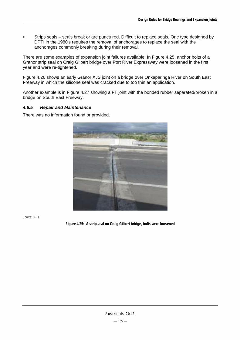
Design Rules for Bridge Bearings and Expansion Joints
A u s t r o a d s 2 0 1 2
— 135 —
Strips seals – seals break or are punctured. Difficult to replace seals. One type designed by DPTI in the 1980's requires the removal of anchorages to replace the seal with the anchorages commonly breaking during their removal.
There are some examples of expansion joint failures available. In Figure 4.25, anchor bolts of a Granor strip seal on Craig Gilbert bridge over Port River Expressway were loosened in the first year and were re-tightened.
Figure 4.26 shows an early Granor XJS joint on a bridge over Onkaparinga River on South East Freeway in which the silicone seal was cracked due to too thin an application.
Another example is in Figure 4.27 showing a FT joint with the bonded rubber separated/broken in a bridge on South East Freeway.
4.6.5 Repair and Maintenance There was no information found or provided.
Source: DPTI.
Figure 4.25: A strip seal on Craig Gilbert bridge, bolts were loosened

Design Rules for Bridge Bearings and Expansion Joints
A u s t r o a d s 2 0 1 2
— 136 —
Source: DPTI.
Figure 4.26: A Granor XJS joint with silicone seal failure
Source: DPTI.
Figure 4.27: A Felspan joint with debonded rubber
4.7 Department of Infrastructure, Energy and Resources, Tasmania (DIER)
4.7.1 Specifications DIER uses the follwing specifications for expansion joints:
Bridgeworks Specification B40 – Expansion Joints, which covers the manufacture, installation and repair of bridge expansion joint
Bridgeworks Specification B44 – Bitumastic Joints, which covers hot or cold applied mastic joints in asphaltic road surfacing at bridge movement joints.

Design Rules for Bridge Bearings and Expansion Joints
A u s t r o a d s 2 0 1 2
— 137 —
4.7.2 Design and Construction DIER has discontinued the use of some joint types including cork or hose filled joints, open gap joints, and sliding steel plates. Cold applied sealant joints have limited use and usually are used for repair work, Asphaltic plug joints are avoided if possible. Fingerplate and modular joints will be limited in future designs.
4.7.3 Testing There was no information found or provided.
4.7.4 Failures Information provided by Graeme Nichols on 15 November 2010 highlighted the following:
Cork or hose filled joints have unsatisfactory performance as they generally leak.
Asphaltic plug joints have poor performance and require specialised construction.
Hot pour sealant and elastomeric compression joints generally perform well.
Fabricated steel fingerplates were used in large bridges. The hold-down bolts need to be correctly tensioned otherwise problems will occur.
Modular joints were used for large bridges only. They are expensive to install and repair and parts availability may be a problem.
4.7.5 Repair and Maintenance There was no information found or provided.
4.8 Department of Lands and Planning, (formerly Department of Planning and Infrastructure) Northern Territory (DPI)
4.8.1 Specifications DPI does not have its own guidelines and uses the TMR’s technical specifications and standards for bridge expansion joints.
4.8.2 Design and Construction Comments from DPI indicated that:
On plank bridges, the simple expedient of grouting the gap between beams never seemed to cause problems. The bridges probably worked as joint-less bridges.
Retrofitting plank bridges with elastomeric concrete noses in conjunction with a Jenie joint or poured in place sealant (XJS system) has been successful and practical.
4.8.3 Testing All testings required follows TMR technical standards and specifications.
4.8.4 Failures The following types of failures have been reported:
Early bridge joints were rubber hose with sealant, and all failed (the hoses came out).

Design Rules for Bridge Bearings and Expansion Joints
A u s t r o a d s 2 0 1 2
— 138 —
Small Wabo compression seals generally failed early in life due to UV or hardening. Modern Wabo style joints with steel angles worked better, but control of joint width was often poor leading to compression failure or the strip seal coming out.
T-plates with asphalt were often placed in failed joints, but the asphalt over the top always failed and the T-plates occasionally came out of the joint and ended up being a hazard to vehicles.
Felspan laminated elastomeric joints are not common. Delamination and failure occurred on Stuart Hwy.
FT joints (rubber bonded fingerplates on rubber bedding) have all failed due to debonding. The joints were all installed on the approach slabs and were never reset to adjust for the rotation of the approach slabs, and therefore the joints were all working as loaded cantilevers. NT has recorded one incident of a loose joint comb being flung into the air by a truck and taking out the sump of a following sedan.
Early plank bridges often had joint angles bolted into longitudinal joints. They were generally light and the angles and bolts failed due to fatigue.
Retrofitting non-composite plank bridges with strip seal joints bolted into longitudinal joints has been problematic.
Leakage through joints of concrete bridges causes staining, but has not been a major cause of corrosion so far.
4.8.5 Repair and Maintenance There was no information found or provided.
4.9 ACT Department of Territory and Municipal Services (ACT TAMS) 4.9.1 Specifications ACT TAMS uses AS 5100.4 and there is no additional specification for bridge expansion joints.
4.9.2 Design and Construction There is no additional requirement.
4.9.3 Testing There is no additional requirement.
4.9.4 Failures Few modes of failure have been observed from recent annual reports. Table 4.6 summaries failure modes of some expansion types that are derived from two recent reports:
Bridge Expansion Joints Program 2007-2008 Report (Roads ACT 2008)
Bridge Expansion Joints Program 2008-2009 Report (Roads ACT 2009).

Design Rules for Bridge Bearings and Expansion Joints
A u s t r o a d s 2 0 1 2
— 139 —
Table 4.6: Typical failures of expansion joints in recent inspections
Joint type Failures
Asphaltic plug joint Deterioration of surface; cracks within and along edges (Figure 4.28)
Steel angles within concrete nosings and compression seals (Wabo or Transflex)
Cracks at the back of angles, instability of angles, seals damaged or deteriorated; broken studs and loose nosing angles (Figure 4.30 and Figure 4.34)
Concrete nosings and compression seals (Wabo or Transflex)
Seals damaged or deteriorated; cracked or broken nosings (Figure 4.29)
XJS joint Cracked nosing, debonding sealant (Figure 4.31)
Felspan T200 with concrete nosings Missing of neoprene anchor pad due to failed bonding with concrete, damaged polymer/epoxy support band (Figure 4.32)
ZE EJ 50S mechanical finger joints Male segment broke loose due to loosening of threaded anchors; debonding of the upper and lower plates from the central neoprene pad (Figure 4.33)
Figure 4.28: Damaged asphaltic plug joint in Bridge 1056, cracks along the edges
Figure 4.29: A compression seal joint with concrete nosing in Bridge 1147, deteriorated seal and damaged nosings

Design Rules for Bridge Bearings and Expansion Joints
A u s t r o a d s 2 0 1 2
— 140 —
Figure 4.30: A compression seal joint with steel angles in Bridge 1249, protrusion of and minor damage/wear to compression seals
Figure 4.31: An XJS joint in Bridge 2097, cracked nosings
Figure 4.32: A Felspan joint in Bridge 2097, damaged joint and missing sections

Design Rules for Bridge Bearings and Expansion Joints
A u s t r o a d s 2 0 1 2
— 141 —
Figure 4.33: A mechanical finger joint in Bridge 2113, a male finger joint segment broken out
Figure 4.34: A deteriorated Transflex joint in Bridge 4087
4.9.5 Repair and Maintenance ACT TAMS has an annual expansion joint inspection program outsourced to a consultant to conduct the inspection and prepare a report detailing recommended remedial work at various nominated bridges. A specification for the work required is prepared based on the inspection report. The repair or replacement work is carried out by a contractor under supervision of ACT TAMS.
4.10 New Zealand Transport Agency (NZTA) 4.10.1 Specifications NZTA’s Transit Bridge Manual (Transit NZ 2003) refers to AS 5100, but has further specific requirements (email from John Reynolds, NZTA 10 December 2010):
Bridges of less than 60 m length and skews less than 30° should have integral abutments.

Design Rules for Bridge Bearings and Expansion Joints
A u s t r o a d s 2 0 1 2
— 142 —
Seismic gap limit is clarified.
ULS loads are clarified.
Where deck joint is anchored by bolts, fully tensioned high tensile bolts are to be used. A clamping force of not less than 500 kN per metre shall be achieved.
AS 5100.4 provisions for drainage are replaced.
Deck joints and adjacent bridge structure has to be designed to allow joint installation following creep and shrinkage movement.
Joint type and selection guidance is provided. Reference is made to UK Highways Agency BD33/94.
Joint sealing element requirements are specified.
Deck concrete nosing requirements specified.
Plug joint requirements are specified.
4.10.2 Design and Construction As in Section 4.10.1.
4.10.3 Testing No additional requirements to AS 5100.4.
4.10.4 Failures Information provided by John Reynolds on 3 November 2010 highlighted the following:
Asphaltic plug joints are used for retrofitting where appropriate, especially to avoid noise issues. Maintenance of these joints is typically required on a 10 year cycle.
Bonded metal/elastomer joints were used extensively in the past. They tend to fail through either metal/elastomer debonding or anchorage failure due to the very high induced forces under movement. They are no longer used.
Compression seal joints have been used extensively for joint retrofitting. They are good joint systems, thus will be used in new designs.
Cold applied sealant joints are used frequently. Problems can occur with concrete-sealant debonding and loss of sealant integrity due to incompatibility with bitumen.
Fabricated steel fingerplate joints often fill with debris. Many have been replaced due to anchorage failures.
Open gaps with protection angles are seldom used in NZTA as they have leak and debris issues.
Sliding steel plate joints have mostly been replaced due to leakage and noise problems.
Strip seals joints are the most common joint used in NZTA for large movements. They perform well and will be continued.
Very few modular joints have been used in NZTA and will be used as required for very large movements.
4.10.5 Repair and Maintenance Guidance is provided in the NZTA Bridge Inspection and Maintenance Manual (Transit NZ 2001).

Design Rules for Bridge Bearings and Expansion Joints
A u s t r o a d s 2 0 1 2
— 143 —
4.11 Summary on Service and Failure Issues 4.11.1 Modes of Failure Table 4.7 summarises common modes of failure of the most common expansion joints as reported by SRAs and suppliers.
Table 4.7: Common modes of failure of expansion joints
Pourable sealant joints Issue raised by
Adhesion and cohesion cracks or loss of the joint sealant and/or hose Cracks and spalls in adjacent deck or headers Section delaminated from the deck Joints are impacted with debris or stones Broken bitumen/cork filler; ripped out in chunks by traffic
RMS, VicRoads, TMR, DPTI, ACT TAMS, NZTA RMS, VicRoads, TMR, ACT TAMS VicRoads, TMR, DIER, DPI RMS VicRoads, TMR
Compression seal joints
Adhesion failures from abrasion or tearing Cracks and spalls in adjacent deck or headers Damaged nosings Damaged or lost seals Seals deteriorated due to UV or hardening Broken stud and loose nosing angles Loss of compression set, falling through the gap, protruding above the trafficked surface
RMS, VicRoads, TMR RMS, VicRoads, TMR, MRWA, ACT TAMS DPTI, VicRoads, TMR DPTI, ACT TAMS DPI ACT TAMS Granor
Strip seal joints
Accumulation of debris Loosened anchor bolts due to vibration Elastomeric seal punctures or breaks up Delamination and failure of Felspan joints Breakage of the aluminium retainers and fixings.
DPTI, RMS DPTI, Trelleborg DPTI DPI, ACT TAMS Granor
Bonded metal/elastomer expansion joints
Glands split or pulled out of the housings Peeled rubber Loosening or breaking of anchorage Cracked concrete or asphalt nosings Leakage Variable field performance
TMR, VicRoads Granor RMS, TMR, VicRoads TMR, VicRoads Granor RMS
Fingerplate joints
Section of finger joint came lose, due to loosening of the threaded anchors Misalignment or broken fingers Water leaking and debris accumulation Corrosion of metal parts Debonding of the upper and lower plates from central neoprene pad (for FT joints) Failed or missing catch drains or membranes Frequent maintenance required Fatigue issues Not compatible with seismic requirements
RMS, MRWA, DPI, ACT TAMS MRWA, VicRoads, TMR MRWA, ACT TAMS, DPI VicRoads, MRWA DPTI, DPI, ACT TAMS, RMS TMR, VicRoads DIER MRWA NZTA
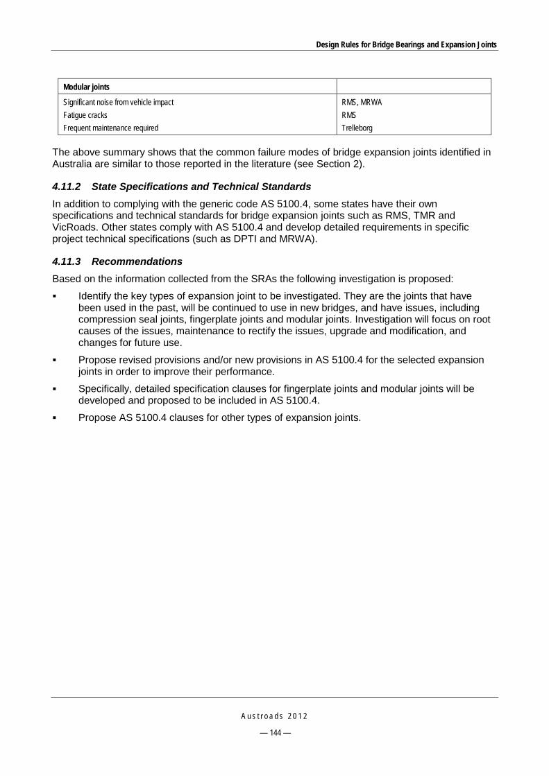
Design Rules for Bridge Bearings and Expansion Joints
A u s t r o a d s 2 0 1 2
— 144 —
Modular joints
Significant noise from vehicle impact Fatigue cracks Frequent maintenance required
RMS, MRWA RMS Trelleborg
The above summary shows that the common failure modes of bridge expansion joints identified in Australia are similar to those reported in the literature (see Section 2).
4.11.2 State Specifications and Technical Standards In addition to complying with the generic code AS 5100.4, some states have their own specifications and technical standards for bridge expansion joints such as RMS, TMR and VicRoads. Other states comply with AS 5100.4 and develop detailed requirements in specific project technical specifications (such as DPTI and MRWA).
4.11.3 Recommendations Based on the information collected from the SRAs the following investigation is proposed:
Identify the key types of expansion joint to be investigated. They are the joints that have been used in the past, will be continued to use in new bridges, and have issues, including compression seal joints, fingerplate joints and modular joints. Investigation will focus on root causes of the issues, maintenance to rectify the issues, upgrade and modification, and changes for future use.
Propose revised provisions and/or new provisions in AS 5100.4 for the selected expansion joints in order to improve their performance.
Specifically, detailed specification clauses for fingerplate joints and modular joints will be developed and proposed to be included in AS 5100.4.
Propose AS 5100.4 clauses for other types of expansion joints.
Design Rules for Bridge Bearings and Expansion Joints
A u s t r o a d s 2 0 1 2
— 145 —
5 INVESTIGATION INTO COMMON FAILURES OF BRIDGE EXPANSION JOINTS
5.1 Proposed Investigation The following most common expansion joint types that experience various failure modes as reported by SRAs are investigated in this section:
compression seal joints
strip seals
bonded metal/elastomer expansion joints
fingerplate joints
modular joints.
Investigation focuses on:
root causes of failures
maintenance to rectify the problems
upgrade and modification
changes for future use.
Recommendations provided in this section can be used as guidelines for the design of these expansion joints.
5.2 Compression Seal Joints 5.2.1 Identified Problems Table 4.7 shows the common modes of failure of compression seal joints. The most typical failures relate to the seal such as deterioration, damage, protruding or missing seal. Failures related to the nosings or waterproofing are also typical.
5.2.2 Root Causes The root causes of expansion joint failures can occur at all stages, including selection of the joint type, design, manufacture, testing, installation and maintenance. For compression seal joints, the possible causes of the failures are:
Selection of the right expansion joint type: compression seal joints should not be used for movements of more than 80 mm and for joints skewed more than 20 degrees.
Deterioration of seal material causes the loss of its ability to spring back or widen when the gap opens up in the winter season after the seal has been compressed during the summer season.
Frequent vibration of the structure causes the seal to protrude above the trafficked surface.
Total shrinkage and movement of the bridge supports can cause the seal to fall through the gap.

Design Rules for Bridge Bearings and Expansion Joints
A u s t r o a d s 2 0 1 2
— 146 —
5.2.3 Suggested Maintenance to Rectify the Problems The following measures can rectify some of the problems:
The condition of the metal protection armour should be periodically inspected for corrosion if the protective coating fails and the protection renewed if required. Slippery surfaces shall be made skid-resistant, as appropriate to the site. Clear the joint gap of debris, and push protruding seals back.
As waterproofing of compression seal joints is not continuous, a complete water drainage system should be provided.
5.2.4 Possible Upgrade and Modification The performance of the joint depends largely on the quality of installation and the correct choice of the seal size and seal material. The following recommendations should be considered (RTA 2008b):
The size of the joint gap opening and bridge temperature should be measured to estimate the probable gap width at the installation between the armouring before ordering the seal to ensure the correct size and depth for the seal.
The joint should not be used in decks with greater than 20 degrees skew.
Compression seals should be proportioned in a working range of 40% to 80% of uncompressed width in accordance with the manufacturer’s specifications to ensure that the seal remains in compression during its service life.
The seals should be set below the deck level and at a uniform depth without excessive longitudinal stretching to prevent protrusion above the roadway surface when fully compressed.
The seals manufactured from ozone-sensitive neoprene compositions should not be used as they may cause compression set after a few years of service.
AS 5100 requires that metal protection armouring shall be provided for this joint type. For older bridges where it is not possible, this type of joint can be installed by forming the gap narrower than the design width and saw cutting with a diamond blade immediately prior to seal installation to ensure correct and uniform width for installation.
Strip seal joints with wedge shaped metal retainers are preferred over compression seal joints as concrete compaction under the steel protection angles is problematic.
In addition, special types of compression seal joints have been available on the local market, such as Wizflex EJS, which is designed based on a combination of compression joint and epoxy-bonded rubber seal technologies. The seal is bonded into the gap walls, which may be steel, concrete, polymer modified concrete or aluminium members, thus providing waterproofing and prevention of dislodgement of the seal (Figure 3.7).
5.2.5 Proposed Changes to AS 5100 for Future Use Provisions for materials, design, manufacture and installation specified in the RMS B310 (RTA 2006c) should be considered for inclusion.
Design Rules for Bridge Bearings and Expansion Joints
A u s t r o a d s 2 0 1 2
— 147 —
5.3 Strip Seal Joints 5.3.1 Identified Problems Table 4.7 shows the common modes of failure of strip seal joints. The most typical failures relate to the anchorage system, seals and the retainers.
5.3.2 Root Causes As mentioned in Section 3, the possible causes of failures of strip seal joints are as follows:
The performance of the joint depends on the correct choice of seal size and seal material. The strip seal joints should only be used for movements less than 85 mm and for joints skewed less than 30 degrees.
The seals not being properly installed by a specialist installer.
Poor installation is usually the main cause, such as poor or non-facilitated torquing of the fixings or poor concrete vibration resulting in voids under the metallic side retainers.
Breakage of the aluminium retainers and fixings due to poor bedding epoxy under the joints.
Vibration is the main cause for failure of the anchorage system.
Debris entrapped on the glands may lead to tearing, puncturing or pulling out of glands under passing traffic or from joint movements. As the joint closes up, the incompressible debris wedges in the gland crevice, which can cause glands to rupture. Traffic wheel loads transferred to glands through built-up debris may tear the gland or pull it out from the metal retainers (RTA 2008b).
5.3.3 Suggested Maintenance to Rectify the Problems Suggested maintenance measures include:
Regularly clearing the join gap and gland of debris and retightening loose nuts/bolts.
Failed glands can be patched using a new length of gland if partial repairs are necessary.
Problems to the performance of joints can be caused by build-up of debris at shoulders and lightly trafficked areas, which can be reduced by scuppers (RTA 2008b).
5.3.4 Possible Upgrade and Modification The following measures are recommendations from various manufacturers and are required by RMS (RTA 2008b):
Even though manufacturers claim a large movement capacity for strip seal joints, the maximum allowable movement is 85 mm to be compliant with AS 5100.4.
The flush internal gland-type is preferred over a draped, single-layer gland-type to avoid debris collection.
Bent or mitred retainers should be used at kerb and traffic barrier upturns.
Anchorages should be designed to resist all static and dynamic loads and should be thoroughly bonded to the concrete. The metal retainers should have regularly spaced vent holes to allow air to escape, unless venting is provided by the anchor bolt holes.
Appropriate torque should be applied to tighten the anchor bolts during installation. The value of appropriate torque should be specified by the manufacturer and supported with experimental data to ensure an axial tension of 65% ULS load in the anchor.

Design Rules for Bridge Bearings and Expansion Joints
A u s t r o a d s 2 0 1 2
— 148 —
The appropriate number and size of anchor bolts should be specified.
Pre-tensioned bolts should be considered.
Failed joints shall be replaced with new strip seal joints.
5.3.5 Proposed Changes to AS 5100 for Future Use Proposed changes to AS 5100 are:
a provision for the requirements for the anchorage system of strip seal joints.
a provisions for the elastomer material, design of retainers and anchorages as well as installation tolerances as specified in B315 (RTA 2007c).
5.4 Bonded Metal/Elastomer Expansion Joints 5.4.1 Identified Problems Table 4.7 shows the common modes of failure of this type of joint. The most typical failures relate to the anchorage system, nosings and the elastomer.
5.4.2 Root Causes The possible causes of failure of bonded metal/elastomer expansion joints include:
The long-term joint movements were not fully calculated in the design, thus the joint design capacity was exceeded.
Shallow installation depth and the joint’s high stiffness may cause high horizontal forces on adjacent decks, thus causing damage on the nosings.
The failure of the anchorage system may be caused by shearing of the bolts due to direct impact from vehicles if the panels are not protected by an impact-absorbing header material.
5.4.3 Suggested Maintenance to Rectify the Problems Anchorage bolts should be re-tightened periodically to compensate for creep of the elastomer and other loosening effects (RTA 2008b).
5.4.4 Possible Upgrade and Modification The following recommendations should be considered (RTA 2008b):
This joint should be used with caution due to its high replacement cost and variable field performance.
Selection of the correct size and correct installation play an important role in ensuring a good performance.
The bridge temperature at the time of installation should be taken into account when calculating the joint gap. If the joint is installed at too cold a temperature, the joint may buckle up in the middle and result in damage by traffic in hot weather. If setting the joint in hot weather, excessive stretching in cold weather later may damage the elastomer or the anchorages.
It may be necessary to use adhesive sealants and to jack segmental panels together during installation to minimise leakage.

Design Rules for Bridge Bearings and Expansion Joints
A u s t r o a d s 2 0 1 2
— 149 —
5.4.5 Proposed Changes to AS 5100 for Future Use Proposed changes to AS 5100 are:
Provisions on the requirements for the anchorage system and installation tolerances of bonded metal/elastomer joints should be included.
Provisions on the skid resistance, profile and transverse movement of the joint as specified in the RMS’s B318 (RTA 2008c) should be considered for inclusion.
5.5 Fingerplate Joints 5.5.1 Identified Problems Table 4.7 shows the most common modes of failure of fingerplate joints. The most typical failures relate to damage of the anchorage system.
In addition, one of the disadvantages of fingerplate joints is their limited capacity for accommodating differential movements (deflection, rotation or settlement) across the joint and they should not be used if significant movements from these effects are expected (RTA 2008b).
5.5.2 Root Causes Root causes of problems include:
Poor concrete vibrating practices and poor or inadequate tensioning procedures for anchor bolts are the predominant root causes of any in-service failures of finger joints (Section 3.1.2).
Fingerplate joints should only be used for movements less than 200 mm because fatigue failure of fingers is of concern. In addition, the fingers may have locking-up issues when the joint is in a fully closed position, not allowing any lateral movement (Section 3.3.2).
Unacceptable noise from a rough riding surface may occur due to anchorage problems or the vertical misalignment of the fingers. Failures of the hold-down cap screws or the base plate anchorages may cause loose plates, which may be a severe hazard (RTA 2008b).
5.5.3 Suggested Maintenance to Rectify the Problems The following guidelines for maintenance of fingerplate joints are proposed (RTA 2008b):
Regular inspection and monitoring of these joints is required for public safety.
Drainage troughs should be cleaned at least once a year, or more often as required.
Damaged fingers should be repaired.
The joint should be kept free of corrosion.
Any loose nuts or screws should be investigated and remedial action taken urgently, as loose nuts or screws will quickly result in fatigue failure of the anchor bolts and uplift of the fingerplates under traffic.
5.5.4 Possible Upgrade and Modification The following recommendations should be considered (RTA 2008b):
A minimum permanent opening of the gap should be specified to prevent the joint from closing up at high temperatures.
Design Rules for Bridge Bearings and Expansion Joints
A u s t r o a d s 2 0 1 2
— 150 —
Fingerplates should have adequate stiffness to prevent excessive vibration and have sufficient flexural capacity to prevent bending and fatigue issues.
Fingers should be aligned in the direction of movement to avoid exerting excessive forces on opposing fingers.
Anchorages shall have sufficient tensile and shear strength to resist loads from heavy traffic including impact. To prevent fatigue failures of the anchorages sufficient bolt tension is required such that the load in the bolt does not change under the design ULS traffic load.
Long debonded anchor bolts to avoid the use of base plates should be considered in new designs.
Stainless steel drainage troughs with cross-falls of at least 8% should be provided to prevent water and debris accumulation. Stainless steel should be used for bolts, nuts and washers.
In new, long bridges with significant creep and shrinkage, resetting of fingerplates should be considered by providing extra bolt holes in the plates.
In addition, modern fingerplate joints are available on the market with special features that help to address the causes of the joint failures. The pre-tensioned bolts, as used in Cipec and Etic joints by Granor (Section 3.1.1), create a permanent compression stress between the joint and the structure, thus providing good resistance against vibrations and fatigue effects. The pre-tensioned fingers that are used in the TensaFlex sliding finger system by Megaba (Moor 2006), combined with a flexible and shock-absorbing design, help to protect the bridge structure underneath from fatigue-related problems and improve the capacity for accommodating different deflection, rotation or settlement across the joint.
5.5.5 Proposed Changes to AS 5100 for Future Use AS 5100.4 has set out the requirements for the maximum opening between adjacent finders and the minimum overlap of the fingers; however, provisions for the design of fingerplate joints have not been provided. It is recommended that a special clause for fingerplate joints be included in the future revision.
In addition, the following findings from recent RMS position papers should be considered for inclusion (RTA 2011, RTA 2008e, RTA 2005e):
Variable tyre contact areas should be used for different limit states when designing fingers and anchorages.
The supplier of the joint should provide calculations to show the relationship between the applied torque and the resulting axial hold-down force provided by the anchors. Appropriate tests should be performed to determine the tightening factor used in the calculation.
A minimum of M20 grade 8.8 anchors at 200 mm spacings at each side of the joint should be used.
Adequate preload should be maintained in the bolt to prevent vibration loosening.
5.6 Modular Joints 5.6.1 Identified Problems As summarised in Table 4.7, the following failures have been reported by SRAs:
significant noise from vehicle impact
fatigue cracks

Design Rules for Bridge Bearings and Expansion Joints
A u s t r o a d s 2 0 1 2
— 151 —
frequent maintenance required.
In addition, as mentioned in Section 2.2.9, more possible failures related to modular expansion joints have been reported in the literature as follows:
water leakage at seal splice
debris accumulated in seals
reflective cracks in the concrete deck directly above the support boxes
corrosion of metal components.
5.6.2 Root Causes As pointed out by Kaczinski et al. (1996), critical factors affecting the performance of modular expansion joints can be classified in three categories: loading and structural response, fatigue resistance, and construction and durability. The first two categories relate to dynamic behaviour of the joint structure (Ancich & Bhavnagri 2006, Ancich & Chirgwin 2006, Ancich & Bradford 2006, and Ancich et al. 2006). It is also mentioned by Braun (1996) that unrealistic load models and unsuitable design solutions have been used in the design. The last category may include the following causes:
Poor concrete consolidation around support boxes and edge beams. This causes differential settlement of support boxes, increasing the span of the centre beams which results in increased live load stress ranges.
Accidental casting of the concrete into the support boxes preventing the thermal movement of support boxes.
Reflective cracking of the concrete deck directly above the support boxes that can adversely affect the durability of the joint.
Accessibility issues.
5.6.3 Suggested Maintenance to Rectify the Problems The following maintenance measures are suggested:
Inspection should be frequent (once a year) to check the replaceable components such as springs and buffers (Section 3.3.2).
The joint shall be maintained in accordance with the maintenance manual supplied with the joint (RTA 2008b). The required inspection and maintenance schedule for the joint, together with work procedures required carrying out repairs and/or replacement of each component of the joint should be followed accordingly.
Noise problem of modular expansion joints can be treated by installing a Helmholtz absorber at the long walls of the abutment cavity of the bridge (RTA 2004).
5.6.4 Possible Upgrade and Modification The environmental noise problem associated with modular expansion joints can be reduced by providing noise abatement equipment. It is recommended that all abutments underneath the joints shall have sufficient space within the abutment cavity if the installation of a Helmholtz absorber for noise abatement is required after post-commissioning noise measurements identify an actual or likely noise nuisance. Sufficient space shall also be provided for inspection and maintenance of the joint (RTA 2004).

Design Rules for Bridge Bearings and Expansion Joints
A u s t r o a d s 2 0 1 2
— 152 —
Close cooperation between the designer, contractor, and joint manufacturer is required to ensure good detail design, thus reducing placement problems during joint installation (AASHTO 2004).
5.6.5 Proposed Changes to AS 5100 for Future Use It should be noted that these joints are predominately proprietary products, designed and fabricated to in-house specifications. The nature of the product is such that external expertise to analyse the design is not readily available. It is recommended that improvements in the specifications are made by stipulating the need for designs to incorporate easier removability and replacement of critical damping bearings and other steel component only via access to the underside of the joint system (Section 3.1.2).
The specific provisions for modular expansion joints in AS 5100.4 should be revised incorporating the provisions of B316 (RTA 2005d) and/or further tests on existing installed modular joints (Section 3.1.2).
5.7 Proposed Changes for Other Joint Types For other joint types that have not been mentioned in the detailed investigation, the following are noted (RTA 2008b):
Only the cold applied variants of sealant type joints are permitted for continued use for small movement joints.
Further use of several joint types is prohibited, including hot poured sealant, moulded elastomer with strip seals, sliding steel plate, and open gap without protection angles.
Joints for use following site-specific study include asphalt plug, metal fingers bonded to elastomer, and open gap with protection angles.
Damaged or discontinued joints are recommended to be replaced by cold applied sealant, compression seal, strip seal or fingerplate joints.
5.8 Selection of Expansion Joints The selection criteria for expansion joints should be based on the performance requirements, which include (Austroads 2001):
Full range of structural movements and rotations: no excessive stresses in the joint or the structure.
Capacity to withstand static loads and loads due to vehicular impact and temperature variation.
Good anchorage system: no anchorage failure during service life.
Watertight: no impact on the bridge components underneath.
Good riding quality: skid resistance and slip resistance; load bearing seal or cover plate may be needed.
No generation of excessive noise.
Durability for environmental impacts: corrosion, ozone, sunlight, water, grit, chemicals; wear, weathering, ageing.
Service life.
Easy to inspect, ease of maintenance and part replacement.

Design Rules for Bridge Bearings and Expansion Joints
A u s t r o a d s 2 0 1 2
— 153 —
Suitable for the skew of the bridge.
Installation time, construction tolerances, and cost.
Availability of parts and repair.
Of the above criteria, the selection of expansion joints is mainly based on the applicable movement range of the joint. Table 5.1 lists the applicable movement ranges for a number of popular expansion joint systems based on the manufacturers’ and suppliers’ product specifications.
Table 5.1: Applicable movement ranges of popular expansion joints
Expansion Joints Movement ranges by manufacturers
(mm)
Other conditions of use
MBJS Wabo MBJS Maurer Sohne
Up to 2000 > 160
Curve structure; skew up to 50 degrees
Fingerplate Steel fingerplate, ETIC series SFEJ Cast aluminium finger ETIC series EJ ETIC finger joint EJ80, EJ110, EJ160
Up to 500 Up to 300
< 80, < 110, < 160
Cast aluminium triangular shape fingers can be used for skew applications.
Bonded metal/elastomer Granor Waboflex, Transflex
50-330
Strip seal Ausflex AC and Ausflex AC-AR Miska ND, NF gland TESA SSA 100, TESA SSC 100
< 75, < 100, < 125
85-125 < 125
Can be used for skew and vertical misalignment
Compression seal Wabo (WA, WJ) Ausflex (EF, GC, WG) Wizflex Miska (N, NH and NC series)
12-79
14-25, 32-46, 35-60
< 72
Cold applied sealant Granor XJS TESA PHS
Gaps 25-75, Movements +100/-50
gap width
Asphaltic plug Prismo-ThormaJoint
< 50
The following guidelines are proposed:
For very small movements (< 25 mm), suitable expansion joints are pourable sealant and compression seal.
For a movement range of 25 mm to 85 mm, compression seals and strip seals can be used for normal applications while a fingerplate joint (with cast aluminium triangle shape finger) can be used for skew bridges.

Design Rules for Bridge Bearings and Expansion Joints
A u s t r o a d s 2 0 1 2
— 154 —
For a movement range of 85 mm to 125 mm, bonded metal/elastomer and fingerplate joints are applicable. It should be noted that although the strip seals can accommodate a movement of up to 125 mm, it is limited by the AS 5100.4 requirement for a maximum gap of 85 mm.
For a movement range of 125 mm to 330 mm, fingerplate joints and bonded metal/elastomer joints are applicable. An MBSJ can also be considered for this movement range.
For a movement of less than 500 mm, a fingerplate joint or a MBSJ can be selected.
MBSJ is the only joint system that can be applicable for movements of larger than 500 mm.
If a fingerplate joint is selected for a movement of larger than 200 mm, special attention should be paid to control the fatigue failure of the fingers.

Design Rules for Bridge Bearings and Expansion Joints
A u s t r o a d s 2 0 1 2
— 155 —
6 GENERIC SPECIFICATION FOR BRIDGE EXPANSION JOINTS
This generic specification is reproduced based on AS 5100.4 Clause 17. Other related clauses of AS 5100.4 are applicable.
6.1 General Same as Clause 17.1, AS 5100.4.
Principally, expansion joints must perform the functions required in Section 2.1.2 of this report.
6.2 Joint Types Joints shall be categorised as follows:
Pourable seal joints: are the joints filled with pourable joint sealant or asphalts. They include asphaltic plug, cork or hose filled, hot poured sealant, cold applied sealant, semi-rigid epoxy.
Compression joint seals: include all joints using preformed compression type seals such as plastic foam strips and rubber-based hose joints.
Assembly joint/seals: are the joints which have an assembly mechanism which consists of end dams bolted down to the deck with a gland or gland type seal between. They include moulded elastomer with strip seal, strip seal, bonded metal/elastomer and modular joints.
Open expansion joints: include joints with or without steel edge armourings.
Sliding joints: are the joints constructed mainly of steel which move or slide over or within a mating element on the other side. These joints may have a compression seal, gland, membrane or catch drain underneath. These joints include steel sliding plates, steel finger joints, metal fingers bonded to elastomer, fabricated steel fingerplates, and saw tooth.
Fixed joints: are the joints where the decks are cast against each other or with a thin separator such as cork, bitumen impregnated fibreboard, styrene sheets or malthoid sheets.
6.3 Requirements Same as Clause 17.3, AS 5100.4.
6.4 Anchorage of Deck Joints Further to the requirements of AS 5100.4 Clause 17.4, the supplier of the joint shall provide calculations to show the relationship between the applied torque and the resulting axial hold-down force provided by the anchors. The nut/thread friction ‘k’ factor used in these calculations shall be determined by testing a batch of 10 anchors in a NATA laboratory approved to conduct these tests. The calculations shall be completed or verified by an engineer with Chartered status of the Institute of Engineers Australia. A minimum of M20 grade 8.8 anchors at 200 mm spacings each side of the joint shall be used.
6.5 Drainage Same as Clause 17.5, AS 5100.4.
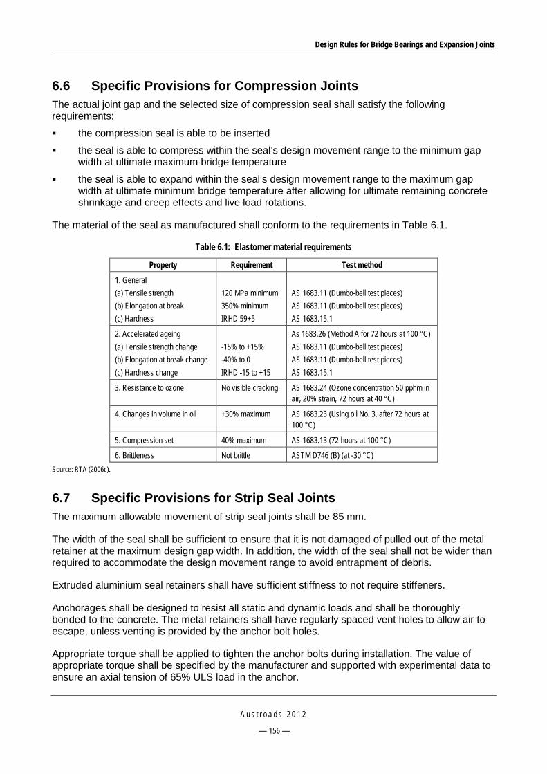
Design Rules for Bridge Bearings and Expansion Joints
A u s t r o a d s 2 0 1 2
— 156 —
6.6 Specific Provisions for Compression Joints The actual joint gap and the selected size of compression seal shall satisfy the following requirements:
the compression seal is able to be inserted
the seal is able to compress within the seal’s design movement range to the minimum gap width at ultimate maximum bridge temperature
the seal is able to expand within the seal’s design movement range to the maximum gap width at ultimate minimum bridge temperature after allowing for ultimate remaining concrete shrinkage and creep effects and live load rotations.
The material of the seal as manufactured shall conform to the requirements in Table 6.1.
Table 6.1: Elastomer material requirements
Property Requirement Test method
1. General (a) Tensile strength (b) Elongation at break (c) Hardness
120 MPa minimum 350% minimum IRHD 59+5
AS 1683.11 (Dumbo-bell test pieces) AS 1683.11 (Dumbo-bell test pieces) AS 1683.15.1
2. Accelerated ageing (a) Tensile strength change (b) Elongation at break change (c) Hardness change
-15% to +15% -40% to 0 IRHD -15 to +15
As 1683.26 (Method A for 72 hours at 100 °C) AS 1683.11 (Dumbo-bell test pieces) AS 1683.11 (Dumbo-bell test pieces) AS 1683.15.1
3. Resistance to ozone No visible cracking AS 1683.24 (Ozone concentration 50 pphm in air, 20% strain, 72 hours at 40 °C)
4. Changes in volume in oil +30% maximum AS 1683.23 (Using oil No. 3, after 72 hours at 100 °C)
5. Compression set 40% maximum AS 1683.13 (72 hours at 100 °C)
6. Brittleness Not brittle ASTM D746 (B) (at -30 °C) Source: RTA (2006c).
6.7 Specific Provisions for Strip Seal Joints The maximum allowable movement of strip seal joints shall be 85 mm.
The width of the seal shall be sufficient to ensure that it is not damaged of pulled out of the metal retainer at the maximum design gap width. In addition, the width of the seal shall not be wider than required to accommodate the design movement range to avoid entrapment of debris.
Extruded aluminium seal retainers shall have sufficient stiffness to not require stiffeners.
Anchorages shall be designed to resist all static and dynamic loads and shall be thoroughly bonded to the concrete. The metal retainers shall have regularly spaced vent holes to allow air to escape, unless venting is provided by the anchor bolt holes.
Appropriate torque shall be applied to tighten the anchor bolts during installation. The value of appropriate torque shall be specified by the manufacturer and supported with experimental data to ensure an axial tension of 65% ULS load in the anchor.

Design Rules for Bridge Bearings and Expansion Joints
A u s t r o a d s 2 0 1 2
— 157 —
The appropriate number and size of anchor bolts shall be specified on the design drawing.
The material of the seal as manufactured shall conform to Table 6.1.
6.8 Specific Provisions for Modular Deck Joints In addition to the requirements of AS 5100.4, the design service life of different joint components shall be:
A minimum of 15 year service life and to be replaced without traffic closures for compression control springs and support bearings.
A minimum of 20 year service life and to be replaced with either a total road closure not exceeding 2 hours or not more than two lanes of the bridge at a time closed to traffic for joint seals.
A minimum of 100 year service life for centre beams, support bars and support boxes, including welded attachments.
Sufficient space for inspection, maintenance and replacement of joint components shall be provided.
A maintenance manual shall be provided simultaneously with the delivery of the joint. The manual shall detail the required inspection and maintenance schedule for the joint, together with work procedures required to carry out repairs and/or replacement of each component of the joint.
The material of the seal as manufactured shall conform to Table 6.1. Materials of other components shall conform to AS 5100.4.
6.9 Specific Provisions for Fingerplate Joints The design of fingerplate joints shall meet the following requirements:
The maximum opening between adjacent fingers on the same side of the joint shall be 50 mm. Further consideration is required for bicycles travelling over longitudinal slots.
The minimum overlap of the fingers shall be 15 mm for the worst combination of movements. This occurs at the lowest temperature after all concrete creep and shrinkage has taken place.
In the longitudinal direction, the minimum joint opening shall be zero. A minimum permanent opening may be specified to ensure the joint does not close up at high temperatures.
The fingerplate shall have adequate stiffness to prevent excessive vibration and have sufficient flexural capacity to prevent bending and fatigue failures. Refer to RMS position papers (RTA 2011) for design guidelines.
The finger shall be aligned at the direction of movement to avoid exerting excessive forces on opposing fingers.
Anchorages shall have sufficient tensile and shear strength to resist loads from heavy traffic including impact, and sufficient bolt tension so that the load in the bolts does not change under the design ULS traffic load, to prevent fatigue failures of the anchorages.
Fingerplate joints shall have stainless steel drainage troughs with cross-falls of at least 8% to prevent ponding and debris accumulation.

Design Rules for Bridge Bearings and Expansion Joints
A u s t r o a d s 2 0 1 2
— 158 —
The supplier of the joint shall provide calculations to show the relationship between the applied torque and the resulting axial hold-down force provided by the anchors.
A minimum of M20 grade 8.8 anchors at 200 mm spacings at each side of the joint shall be used.
6.10 Joint Sealants Same as Clause 17.8, AS 5100.4.
6.11 Installation Same as Clause 17.7, AS 5100.4.
6.12 Monitoring, Maintenance and Rehabilitation This section have been reproduced based on BTD 2008/10 (RTA 2008b).
6.12.1 General Bridge expansion joints shall be inspected at regular bridge inspection programs. When a joint is in need of attention, the available options are to immediately start maintenance or rehabilitation work or to monitor the joint’s behaviour and its overall effects on the bridge and hazard to road users when deciding on the course of action to be taken.
Spray seals or asphalt shall not be permitted to overlay on top of joints as this will cause damage to the joint, inhibit its performance and cause ride and later bridge maintenance problems.
6.12.2 Monitoring Monitoring a joint can be undertaken to better understand the condition of the joint and severity of the damage or evaluate rehabilitation methods. Monitoring can assist programming of joint works and assessment of functionality of the joint.
Monitoring methods and tools shall be carefully selected to provide ample warning about any impending failure or to provide sufficient information to make the right decisions. Risk management techniques can be applied to aid decision making.
6.12.3 Maintenance of Joints Adequate maintenance of joints ensures the safety of the travelling public, maintains the load carrying capacity of the bridge and its serviceability performance at an acceptable level and minimises the costs of repair and bridge life cycle cost.
Regular inspections of joints shall be conducted to identify maintenance or rehabilitation needs and preventative measures required to improve the quality of joints.
Joints shall be maintained starting from their installation when the bridge is new and shall continue throughout the whole life of the bridge, to prevent the need for major expensive rehabilitation works.
Regular maintenance of joints shall be ongoing to avoid serious consequences.

Design Rules for Bridge Bearings and Expansion Joints
A u s t r o a d s 2 0 1 2
— 159 —
6.12.4 Joint Rehabilitation Joint failures arising from wear and tear, use of inappropriate materials, poor installation, heavy and repetitive wheel loads, deterioration or decay of materials, changes in bridge articulation, underestimations of concrete creep and shrinkage, or a combination of these effects shall be considered to carry out rehabilitation or repair work. Deterioration of steel members can also be due to corrosion, fatigue, welding cracks and imperfections, buckling, loose connections, or failure of corrosion protection systems.
Any joint requiring corrective action shall be checked to assess whether a replacement or a repair is necessary.
If joint replacement is required, an acceptable joint type shall be identified that can cater for the required movement range.
The remaining bridge life and difficulties in placing anchors between existing steel reinforcement shall be considered during the design of rehabilitation works.
Wherever possible and depending on the site, a failed joint shall be fully replaced by a new joint conforming to AS 5100.4.
Design Rules for Bridge Bearings and Expansion Joints
A u s t r o a d s 2 0 1 2
— 160 —
7 CONCLUSIONS The project has involved a literature review, consultation with manufacturers and consultation with SRAs to identify the most common modes of failure of bridge expansion joints in Australia. The following conclusions are noted:
A number of failure modes have been reported in both the literature and current Australian practice. There are as many joint-specific failure modes as common failure modes.
The root causes of failures may come from all stages including design, manufacture, installation and maintenance. However, the most common cause of failures relates to the design and installation stage.
In addition to following AS 5100.4, each SRA has developed and/or used its own technical guidelines and specifications. The requirements, particularly in materials and testing, may vary significantly, creating a level of inconsistency throughout the SRAs and difficulties for manufacturers, suppliers and contractors.
There is a lack of consistent procedures for acceptance and control measures of new products, especially of imported products.
The recommendations made in Section 5 can be used as design rules to overcome the performance issues for each type of expansion joint.
Section 6 can be used as the basis to develop generic code provisions and specifications for joints.

Design Rules for Bridge Bearings and Expansion Joints
A u s t r o a d s 2 0 1 2
— 161 —
REFERENCES AASHTO 1998, AASHTO LRFD Bridge construction specifications, 1st edn, American Association of State
Highway and Transportation Officials (AASHTO), Washington, DC, USA.
AASHTO 2004, AASHTO LRFD Bridge construction specifications, 2nd edn, American Association of State Highway and Transportation Officials (AASHTO), Washington, DC, USA.
AASHTO 2007, ‘Joints and bearings’, section 14 (SI) in AASHTO LRFD Bridge design specifications: dual units, 4th edn, LRFDEM-4-CD, American Association of State Highway and Transportation Officials (AASHTO), Washington, DC, USA.
AASHTO 2010, ‘Joints and bearings’, section 14 in AASHTO LRFD Bridge design specifications, 5th edn, American Association of State Highway and Transportation Officials (AASHTO), Washington, DC, USA.
AASHTO & NSBA 2005, Steel bridge bearing design and detailing guidelines, AASHTO document SBB-1G 9.1- 2004, American Association of State Highway and Transportation Officials (AASHTO), Washington, DC, USA.
Ancich, EJ & Bhavnagri, V 2006, ‘Fatigue comparison of modular bridge expansion joints using multiple bridge design code approaches’, World congress of joints, bearings, and seismic systems for concrete structures, 6th, Halifax, Nova Scotia, Canada, The International Joints & Bearings Research Council & American Concrete Institute, Farmington Hills, MI, USA.
Ancich, EJ & Bradford, P 2006, ‘Modular bridge expansion joint dynamics’, World congress of joints, bearings, and seismic systems for concrete structures, 6th, Halifax, Nova Scotia, Canada, The International Joints & Bearings Research Council & American Concrete Institute, Farmington Hills, MI, USA.
Ancich, EJ & Chirgwin, GJ 2006, ‘Fatigue proofing of an in-service modular bridge expansion joint’, World congress of joints, bearings, and seismic systems for concrete structures, 6th, Halifax, Nova Scotia, Canada, The International Joints & Bearings Research Council & American Concrete Institute, Farmington Hills, MI, USA.
Ancich, EJ, Forster, G & Bhavnagri, V 2006, ‘Modular bridge expansion joint specifications and load testing’, Austroads bridge conference, 6th, 2006, Perth, Western Australia, Austroads, Sydney NSW, 15 pp.
Austroads 1992, Austroads bridge design code: section 4: bearings and deck joints, AP-15.4, Austroads, Sydney, NSW.
Austroads 2009, Guide to bridge technology: part 3: typical superstructures, substructures and components, AGBT03/09, Austroads, Sydney, NSW.
Baker, RJ & Adams, BW 1996, ‘A new generation of APJ design: the cold plug joint’, World congress on joint sealants and bearing systems for concrete structures, 4th, Sacramento, California, American Concrete Institute, Farmington Hills, MI, USA, pp. 353-63.
Barnard, CP & Cunninghame, JR 1997, Improving the performance of bridge expansion joints, report 236, Transport Research Laboratory, Crowthorne, UK.
Braun, J 1996, ‘Development of expansion joints and bearings’, World congress on joint sealants and bearing systems for concrete structures, 4th, Sacramento, California, American Concrete Institute, Farmington Hills, MI, USA, pp.1157-70.

Design Rules for Bridge Bearings and Expansion Joints
A u s t r o a d s 2 0 1 2
— 162 —
Chang, LM & Lee, YJ 2002, ‘Evaluation of performance of bridge deck expansion joints’, Journal of Performance Of Constructed Facilities, vol.16, no.1, pp. 3-9.
Chen, WF & Duan, L 2000, Bridge engineering handbook, CRC Press, Boca Raton, FL, USA.
Chen, WF & Duan, L 2003, Bridge engineering substructure design, CRC Press, Boca Raton, FL, USA.
Dahir, SH & Mellott, DB 1987, ‘Bridge deck expansion joint’, Transportation Research Record, no.1118, pp.16-24.
Davidson, G, Sarmiento, C, Williams, C & Robinson, N 2004, ‘Design, specification, manufacture and testing of laminated elastomeric and pot bearings to AS 5100.4’, Austroads bridge conference, 5th, 2004, Hobart, Tasmania, Austroads, Sydney, NSW, 22 pp.
Dexter, RJ, Connor, RJ & Kaczinski, MR 1997, Fatigue design of modular bridge expansion joints, National cooperative highway research program (NCHRP) report 402, Transportation Research Board, Washington, DC, USA.
Dexter, RJ, Mutziger, MJ & Osberg, CB 2002, Performance testing for modular bridge joint systems, National cooperative highway research program (NCHRP) report 467, Transportation Research Board, Washington, DC, USA.
Dexter, RJ, Osberg, CB, & Mutziger, MJ 2001, ‘Design, specification, installation, and maintenance of modular bridge expansion joint systems’, Journal of Bridge Engineering, vol. 6, no. 6, pp. 529-37.
DIER 2004, Elastomeric bearings, bridgeworks specification B30, Department of Infrastructure, Energy and Resources, Hobart, Tas.
Fleuriot, E, McCulloch, D & Szto, B 2006, ‘The replacement of the expansion joints on the Aplex Fraser bridge’, World congress of joints, bearings, and seismic systems for concrete structures, 6th, Halifax, Nova Scotia, Canada , The International Joints & Bearings Research Council & American Concrete Institute, Farmington Hills, MI, USA.
Forster, G, Anzar, M & Ahmed, T 2009, 'Investigation, assessment, approval and management of bridge deck joints by RTA NSW', Austroads bridge conference, 7th, 2009, Auckland, New Zealand, Convention Management, Auckland, NZ, 12 pp.
Fyfe, ER, Milligan, P & Watson, SC 2006, ‘A discussion of failure modes on high load bridge bearings which have resulted in the current design methods, philosophy, and guidelines for disc bearings’, World congress of joints, bearings, and seismic systems for concrete structures, 6th, Halifax, Nova Scotia, Canada , The International Joints & Bearings Research Council & American Concrete Institute, Farmington Hills, MI, USA.
Gase, PM & Kaczinski, MR 2006, ‘Bridge bearing design and detailing guidelines’, World congress of joints, bearings, and seismic systems for concrete structures, 6th, Halifax, Nova Scotia, Canada , The International Joints & Bearings Research Council & American Concrete Institute, Farmington Hills, MI, USA.
Granor Rubber and Engineering n.d, Granor Rubber and Engineering home page, Bayswater, Vic, viewed 12 October 2010, <http://www.granor.com.au/>.
Issa, MA, Robinson, B & Shahawy, M 1996, ‘On-site evaluation of bridge deck expansion joints’, World congress on joint sealants & bearing systems for concrete structures, 4th, Sacramento, California, American Concrete Institute, Farmington Hills, MI, USA, pp. 561-83.
Design Rules for Bridge Bearings and Expansion Joints
A u s t r o a d s 2 0 1 2
— 163 —
Kaczinski, MR, Dexter, RJ & Connor, RJ 1996, ‘Fatigue design and testing of modular bridge expansion joints’, World congress on joint sealants and bearing systems for concrete structures, 4th, Sacramento, California, American Concrete Institute, MI, USA, pp. 97-111.
Lee, DJ 1994, Bridge bearings and expansion joints, 2nd edn, E&FN Spon, London, UK.
Littlefair, K 2008, ‘Inspection of bridge bearings at Lake Ginninderra, Belconnen,’ Roads ACT, Territory and Municipal Services Directorate, Canberra, ACT.
Ludowici n.d, Engineered products/bridge bearings, Ludowici, Pinkenba, Qld, viewed 12 October 2010, <http://www.ludowici.com.au/web/news.html?newsId=292>.
Lyons, M 2009, ‘Bridge 2097: supplementary report’, Roads ACT, Territory and Municipal Services Directorate, Canberra, ACT.
Majumdar, S & Datta, S 2006, ‘First introduction of disc bearings in India in Bandra Worli Sea Link’, World congress of joints, bearings, and seismic systems for concrete structures, 6th, Halifax, Nova Scotia, Canada, The International Joints & Bearings Research Council & American Concrete Institute, MI, USA.
Marioni, A 2006, ‘The European standard EN 1337 on structural bearings’, World congress of joints, bearings, and seismic systems for concrete structures, 6th, Halifax, Nova Scotia, Canada, The International Joints & Bearings Research Council & American Concrete Institute, MI, USA.
Moor, G 2006, ‘Modern sliding finger expansion joints: minimizing traffic management problems’, World congress of joints, bearings, and seismic systems for concrete structures, 6th, Halifax, Nova Scotia, Canada, The International Joints & Bearings Research Council & American Concrete Institute, MI, USA.
MRWA 2008, Bridge branch design information manual, document 3912/02/01, Main Roads Western Australia, East Perth, WA.
MRWA 2009, Routine visual bridge inspection guidelines, document 6706-02-2234, Main Roads Western Australia, East Perth, WA.
MRWA 2010, Bridge bearings, specification 860, Main Roads Western Australia, East Perth, WA.
QMR 2004, Bridge inspection manual, Queensland Department of Main Roads, Spring Hill, Qld.
QMR 2006, ‘Pot bearing: configuration and typical defects’, BAM advice note no. 63, Queensland Department of Main Roads, Spring Hill, Qld.
Raina, VK 1994, Concrete bridge practice: analysis, design and economics, Tata McGraw Hill, New Delhi, India.
Roads ACT 2008, ‘Bridge expansion joints program 2007-2008’, Roads ACT, Territory and Municipal Services Directorate, Canberra, ACT.
Roads ACT 2009, ‘Bridge expansion joints program 2008-2009’, Roads ACT, Territory and Municipal Services Directorate, Canberra, ACT.
Roeder, CW, Stanton, JF & Campbell, TI 1995, ‘Rotation of high load multirotational bridge bearings’, Journal of Structural Engineering, vol.121, no. 4, pp. 747-56.
Design Rules for Bridge Bearings and Expansion Joints
A u s t r o a d s 2 0 1 2
— 164 —
RTA 1997a, Design of bearings for durability, Chief bridge engineer circular CBE 97/5, Roads and Traffic Authority, Sydney, NSW, viewed 4 July 2011, <http://www.rta.nsw.gov.au/doingbusinesswithus/engineeringpolicies/downloads/bridge_td_2006.html>.
RTA 1997b, Bridge bearings: design for maintenance or replacement, Chief bridge engineer circular CBE 98/8, Roads and Traffic Authority, Sydney, NSW, viewed 4 July 2011, <http://www.rta.nsw.gov.au/doingbusinesswithus/engineeringpolicies/downloads/bridge_td_2006.html> .
RTA 2004, Inspection of modular expansion joint and control of noise, RTA bridge policy circular BCP2004/08, Roads and Traffic Authority, Sydney, NSW, viewed 4 July 2011, <http://www.rta.nsw.gov.au/doingbusinesswithus/engineeringpolicies/downloads/bridge_td_2006.html>.
RTA 2005a, Pot bearings: stainless steel, RTA QA Specification B283, Roads and Traffic Authority, Sydney, NSW, viewed 4 July 2011, <http://www.rta.nsw.gov.au/doingbusinesswithus/engineeringpolicies/bridge_td.html>.
RTA 2005b, Installation of elastomeric bearings for pretensioned concrete girders, RTA bridge policy circulars BCP 2005/03, Roads and Traffic Authority, Sydney, NSW.
RTA 2005c, Pot bearing attachment plates, RTA bridge policy circulars BCP 2005/04, Roads and Traffic Authority, Sydney, NSW.
RTA 2005d, Modular bridge expansion joints, RTA QA specification B316, Roads and Traffic Authority, Sydney, NSW, viewed 4 July 2011, <http://www.rta.nsw.gov.au/doingbusinesswithus/engineeringpolicies/bridge_td.html>.
RTA 2005e, ‘Locking devices for stress bar nuts and caps screws’, RTA position paper, Roads and Traffic Authority, Sydney, NSW.
RTA 2006a, Unreinforced elastomeric bearing pads and strips, RTA QA specification B280, Roads and Traffic Authority, Sydney, NSW, viewed 4 July 2011, <http://www.rta.nsw.gov.au/doingbusinesswithus/engineeringpolicies/bridge_td.html>.
RTA 2006b, Laminated elastomeric bearings, RTA QA specification B281, Roads and Traffic Authority, Sydney, NSW, viewed 4 July 2011, <http://www.rta.nsw.gov.au/doingbusinesswithus/engineeringpolicies/bridge_td.html>.
RTA 2006c, Compression seal expansion joints, RTA QA specification B310, Roads and Traffic Authority, Sydney, NSW viewed 4 July 2011, <http://www.rta.nsw.gov.au/doingbusinesswithus/engineeringpolicies/bridge_td.html>.
RTA 2006d, Cold applied elastomeric joint sealants, RTA QA specification B312, Roads and Traffic Authority, Sydney, NSW, viewed 4 July 2011, <http://www.rta.nsw.gov.au/doingbusinesswithus/engineeringpolicies/bridge_td.html>.
RTA 2007a, Pot bearings: structural steel, RTA QA specification B282, RTA, NSW.
RTA 2007b, Bridge inspection procedure manual, 2nd edn, Roads and Traffic Authority, Sydney, NSW.

Design Rules for Bridge Bearings and Expansion Joints
A u s t r o a d s 2 0 1 2
— 165 —
RTA 2007c, Elastomeric strip seal expansion joints, RTA QA specification B315, Roads and Traffic Authority, Sydney, NSW, viewed 4 July 2011, <http://www.rta.nsw.gov.au/doingbusinesswithus/engineeringpolicies/bridge_td.html>.
RTA 2008a, Installation of bridge bearings, RTA QA specification B284, Roads and Traffic Authority, Sydney, NSW, viewed 4 July 2011, <http://www.rta.nsw.gov.au/doingbusinesswithus/specifications/bridgeworks.html>.
RTA 2008b, Bridge deck joint selection, design, installation and maintenance, bridge technical direction BTD 2008/10, Roads and Traffic Authority, Sydney, NSW, viewed 4 July 2011, <http://www.rta.nsw.gov.au/doingbusinesswithus/engineeringpolicies/bridge_td.html>.
RTA 2008c, Bonded metal-elastomer expansion joints, RTA QA specification B318, Roads and Traffic Authority, Sydney, NSW, viewed 4 July 2011, <http://www.rta.nsw.gov.au/doingbusinesswithus/engineeringpolicies/bridge_td.html>.
RTA 2008d, Proprietary aluminium expansion joints, RTA QA specification B319, Roads and Traffic Authority, Sydney, NSW, viewed 4 July 2011, <http://www.rta.nsw.gov.au/doingbusinesswithus/engineeringpolicies/bridge_td.html>.
RTA 2008e, ‘Design and installation of socket head cap screws and bolts for expansion joint anchorage’, RTA position paper, Roads and Traffic Authority, Sydney, NSW.
RTA 2010a, ‘Design of through-bolts for anchoring expansion joints to concrete bridge decks’, RTA position paper, 14 July 2010, Roads and Traffic Authority, Sydney, NSW.
RTA 2010b, Lists of RTA approved bridge components and systems, bridge technical direction BTD 2008/11, Roads and Traffic Authority, Sydney, NSW, viewed 4 July 2011, <http://www.rta.nsw.gov.au/doingbusinesswithus/engineeringpolicies/bridge_td.html>.
RTA 2011, ‘Design of fingerplate joints’, position paper: revision 3, March 2011, Roads and Traffic Authority, Sydney, NSW.
Shiau, YC, Wang, MT, Huang, CM & Zeng, JY 2008 ‘Discussion of pot bearing for concrete bridge’, International symposium on automation and robotics in construction, 25th, Vilnius, Lithuania, IAARC, Eindhoven, Netherlands, pp. 213-23.
TMR 2009a, Bridge bearings, Main Roads technical standard MRTS81, Queensland Department of Transport and Main Roads, Spring Hill, Qld.
TMR 2009b, Stainless steel bridge bearings, Main Roads technical standard MRTS81a, Queensland Department of Transport and Main Roads, Spring Hill, Qld.
TMR 2009c, Bridge deck expansion joints, Main Roads technical standard MRTS82, Queensland Department of Transport and Main Roads, Spring Hill, Qld.
TMR 2009d, Modular bridge expansion joints, Main Roads technical standard MRTS90, Queensland Department of Transport and Main Roads, Spring Hill, Qld.
TMR 2009e, Design criteria for bridges and other structures, Queensland Department of Transport and Main Roads, Spring Hill, Qld.
TMR 2010, Bridge bearings, Main Roads standard specification MRS 11.81, Queensland Department of Transport and Main Roads, Spring Hill, Qld.

Design Rules for Bridge Bearings and Expansion Joints
A u s t r o a d s 2 0 1 2
— 166 —
Transit New Zealand 2001, Bridge inspection and maintenance manual, revised edn, Transit New Zealand, Wellington, NZ.
Transit New Zealand 2003, Bridge manual, 2nd edn, SP/M/022, Transit New Zealand, Wellington, NZ.
Trelleborg Engineered Systems Australia, Infrastructure: rail, road and bridges, Trelleborg Engineered Systems Australia, Brisbane, Qld, viewed 12 October 2010, < <http://www.trelleborg.com.au.php5-1.dfw1-1.websitetestlink.com/?page_id=493>.
VicRoads 2004a, Supply of elastomeric bearings, standard section 652, VicRoads, Kew, Vic.
VicRoads 2004b, Pot type confined elastomeric bearings, standard section 653, VicRoads, Kew, Vic.
VicRoads 2004c, Installation of elastomeric bearings and pads, standard section 656, VicRoads, Kew, Vic.
VicRoads 2005a, Design of laminated elastomeric bearing, bridge technical notes BTN2003/001, VicRoads, Kew, Vic.
VicRoads 2005b, Procedure for testing pot bearings, bridge technical notes BTN2002/002, VicRoads, Kew, Vic.
VicRoads 2005c, Reinforcement of deck joints, bridge technical notes BTN2002/001 version 1.1, VicRoads, Kew, Vic.
VicRoads 2006, Deck expansion joints, standard section 660, VicRoads, Kew, Vic.
VicRoads 2007, Bridge inspection manual, VicRoads, Kew, Vic.
VicRoads 2010, Design of deck joint for road bridges, bridge technical notes BTN1999/002 version 2.1, VicRoads, Kew, Vic.
Watson, SC 2006, ‘Experience with joint sealing and bearing systems on North American pavements and bridges and a history of involvement with them during the last 60 years’, World congress of joints, bearings, and seismic systems for concrete structures, 6th, Halifax, Nova Scotia, Canada, American Concrete Institute, Farmington Hills, MI, USA.
Standards Australia
AS 5100.4-2004, Bridge design: bearings and deck joints.

INFORMATION RETRIEVAL
Austroads, 2012, Design Rules for Bridge Bearings and Expansion Joints, Sydney, A4, pp. 177. AP-R405-12.
Keywords: bridge bearing, expansion joint, deck joint, bearing, pot bearing, elastomeric bearing, laminated elastomeric bearing, disc bearing, spherical bearing, joint, modular expansion joint, fingerplate joint, MBJS, strip, seal, compression joint, design rule, design, specification, failure, joint failure, bearing failure.
Abstract: In modern bridge structures, bridge bearings and expansion joints are commonly the source of most maintenance and performance issues. In some situations their performance can lead to the closure/failure of major structures and their maintenance can be extremely difficult and costly to implement. Most of these problems can be overcome if robust design and installation rules are implemented to ensure their design and construction deliver highly durable and reliable components, and that the lessons learnt from practice are fully addressed in the future design and maintenance of these components, thus leading to improved performance.
This report develops guidelines for the design and construction of both bridge bearings and bridge expansion joints to overcome performance issues experienced in Australian bridges. The project report includes (i) a review of existing Australian and international literature on bridge bearings and expansion joints, (ii) identification of typical failure modes of various types of bearings and expansion joints observed in Australian current practice, (iii) key issues in design, manufacture, construction and maintenance of bridge bearings and expansion joints experienced by various State Road Authorities and local manufacturers/suppliers, (iv) an investigation into failure modes of some common bridge bearing and expansion joint types as well as recommendations for design, construction and/or maintenance solutions to overcome these identified issues and (v) suggested generic specifications for bridge bearings and expansion joints.