design robot transperineal prostate needle placement mri
TRANSCRIPT
Design of a Robot for Transperineal Prostate NeedlePlacement in MRI Scanner
Gregory S. Fischer1, Julian Iordachita1, Simon P. DiMaio2, Gabor Fichtinger1Center for Computer Integrated Surgery 2Surgical Planning Lab, Department of Radiology
Johns Hopkins University Brigham and Women's Hospital, Harvard UniversityBaltimore, MD, [email protected] Boston, MA, [email protected]
Abstract-Numerous studies have demonstrated the efficacy itor transperineal needle placement. The needles were insertedof image-guided needle-based therapy and biopsy in the man- manually using a guide comprising a grid of holes, with theagement of prostate cancer. Magnetic Resonance Imaging (MRI) patient in the lithotomy position, similarly to the TRUS-guidedis an ideal modality for guiding and monitoring prostatic in-
a
terventions, due to its excellent visualization of the prostate, its aRoach. not al.sa transgluteal approach with 0.2Tsub-structure and surrounding tissues. Despite these advantages, MRI, but did not specifically target the tumor foci [11]. Susilclosed high-field MRI scanners (1.5T or greater) have not et al. described four cases of transperineal prostate biopsy intypically been used in prostate interventions. The strong magnetic a closed-bore scanner, where the patient was moved out offield prevents the use of conventional mechatronics and the the bore for needle insertions and then placed back into theconfined physical space makes it extremely challenging to accessthe patient. We have designed a robotic assistant system that bore to confirm satisfactory placement [12]. Beyersdorff et al.overcomes these difficulties and promises safe and reliable intra- performed targeted transrectal biopsy in a 1.5T MRI unit withprostatic needle placement inside closed high-field MRI scanners. a passive articulated needle guide and have reported 12 casesThe paper explains the design process, component selection and of biopsy to date [13].the system currently being prototyped. Robotic assistance has been investigated for guiding instru-
I. INTRODUCTION ment placement in MRI, beginning with neurosurgery [14]and later percutaneous interventions [15], [16]. Chinzei et al.
One out of every 6 men in the United States will be diag- developed a general-purpose robotic assistant for open MRInosed with prostate cancer at some point in his life [1]. The [17] that was subsequently adapted for transperineal intra-definitive method of diagnosis is core needle biopsy and each prostatic needle placement [18]. Krieger et al. presented a 2-year approximately 1.5M core needle biopsies are performed, degree of freedom (DOF) passive, unencoded and manuallyyielding about 220,000 new prostate cancer cases [1]. If the manipulated mechanical linkage to aim a needle guide forcancer is found to be confined to the prostate, then low- transrectal prostate biopsy with MRI guidance [19]. Withdose-rate permanent brachytherapy-performed by implanting the use of three active tracking coils, the device is visuallya large number (50-150) of radioactive pellets/seeds into the servoed into position and then the patient is moved out ofprostate using thin needles (typically 18G)-is a common treat- the scanner for needle insertion. Other recent developmentsment option [2]. A complex seed distribution pattern must be in MRI-compatible mechanisms include haptic interfaces forachieved with great accuracy in order to eradicate the cancer, fMRI [20] and multi-modality actuators and robotics [21].while minimizing radiation toxicity to adjacent healthy tissues. This work introduces the design of a novel computer-There are over 40,000 brachytherapies performed in the U.S. integrated robotic mechanismfor transperineal prostate needleeach year and the number is steadily growing [3]. Transrectal placement in 3T closed-bore MRI. The mechanism is capableUltrasound (TRUS) is the current "gold standard" for guiding of orienting and driving the needle, as well as ejecting ra-both biopsy and brachytherapy due to its real-time nature, low dioactive seeds or harvesting tissue samples inside the magnetcost, and apparent ease of use [4]. However, current TRUS- bore, under remote control of the physician without movingguided biopsy has a detection rate of 20-30% [5], primarily the patient out of the imaging space. This enables the usedue to the low sensitivity (60%) and poor positive predictive of real-time multi-modality imaging for precise placementvalue (25%) of ultrasound [6]. Furthermore, TRUS cannot of needles in soft tissues. In addition to structural images,effectively monitor the implant procedure as implanted seeds protocols for diffusion imaging and MR spectroscopy willcannot be seen in the image. MRI seems to possess many of be available intraoperatively, promising enhanced visualizationthe capabilities that TRUS is lacking. It has high sensitivity and targeting of pathologies. Accurate and robust needle place-for detecting prostate tumors, high spatial resolution, excellent ment devices, navigated based on such image guidance aresoft tissue contrast, and multiplanar volumetric imaging capa- becoming invaluable clinical tools and have clear applicationsbilities [7]. Closed high-fieldMRI has not been widely adopted in several other organ systems. A description of how thisfor prostate interventions, because high magnetic field strength robot fits into the broader complete interventional system isand confined physical space present formidable challenges for described in [22].performing needle placement procedures inside of the imager. The paper is organized as follows: Section II describes the
The clinical efficacy of MRI-guided prostate brachytherapy workspace analysis and design requirements for the proposedand biopsy was demonstrated by D'Amico, Tempany, et al. at device, and Section III details of our prototype design. Pre-the Brigham and Women's Hospital using a O.5T open-MRI liminary results are presented in Section IV with conclusionsscanner [8]-[10]. The MR images were used to plan and mon- in Section V.
1-4244-971 3-41061$20.OO ©2006 IEEE 592
G. S. Fischer, I. lordachita, S. P DiMaio, G. Fichtinger Design of a Robot for Transperineal Prostate Needle Placement in MRI Scanner
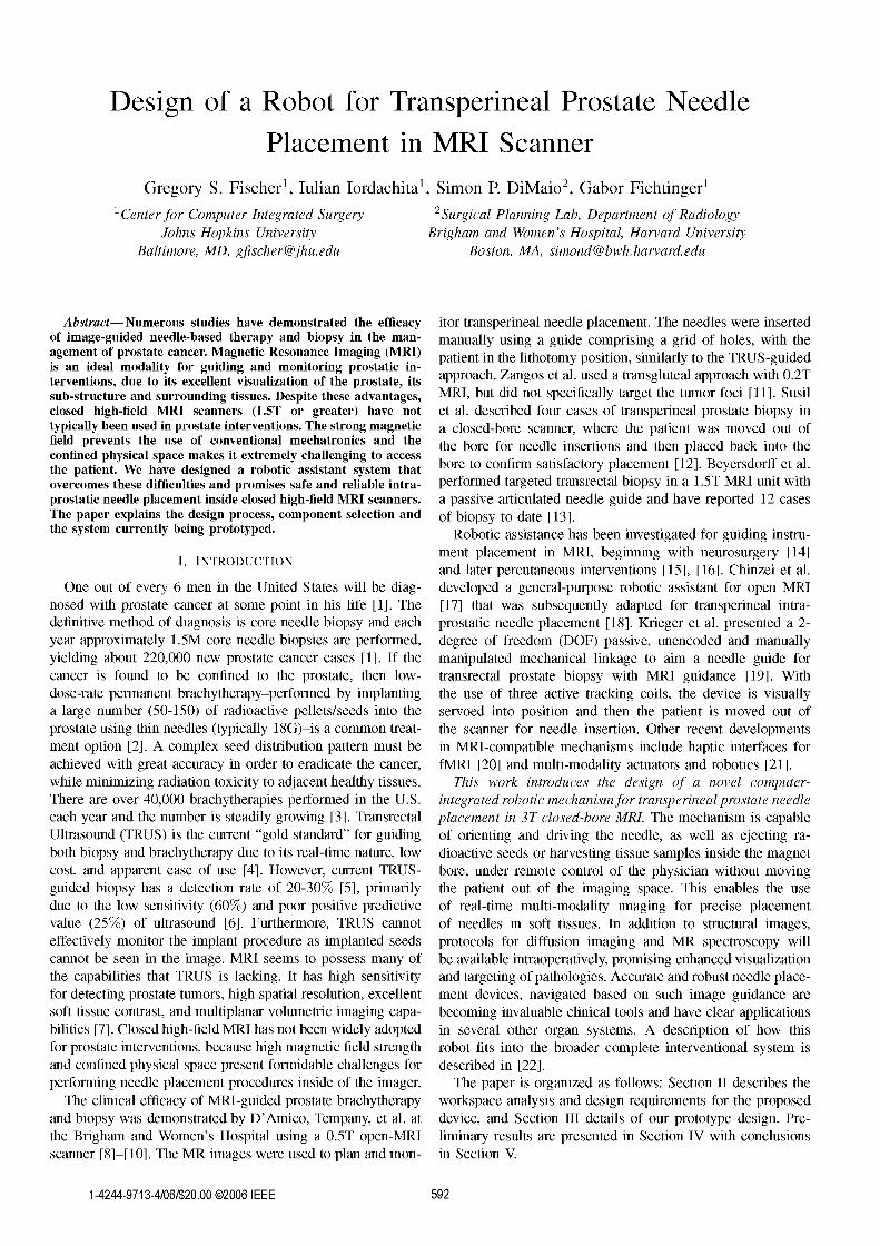
Fig. 1. Patient positioning(left) and workspace available inside leg support I access tunnel(right).
II. DESIGN REQUIREMENTS B. System Requirements
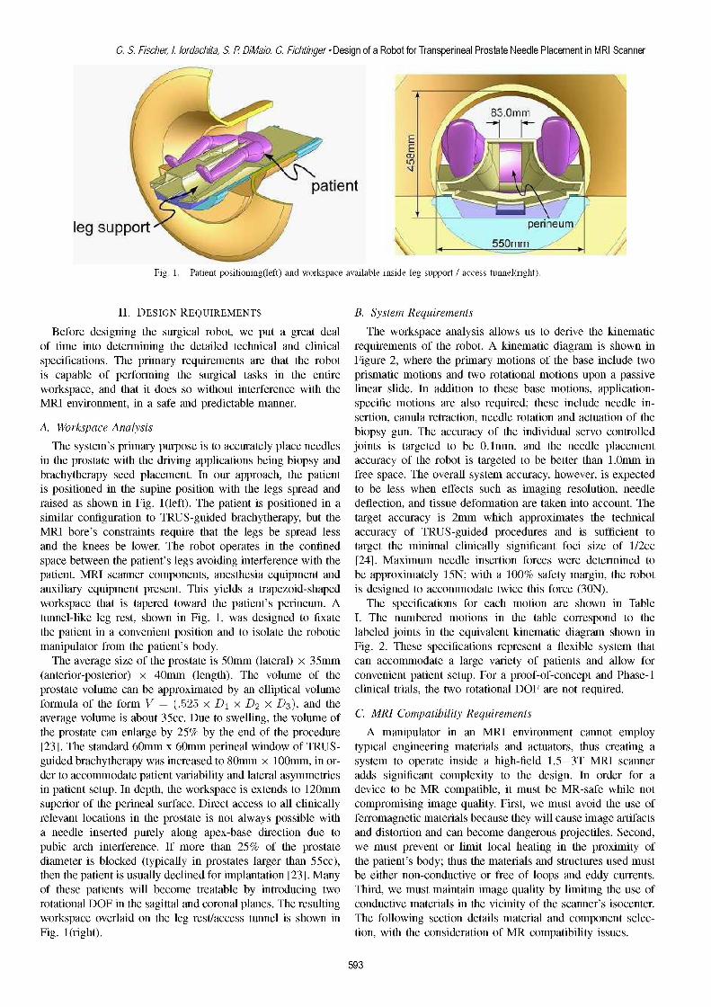
Before designing the surgical robot, we put a great deal The workspace analysis allows us to derive the kinematicof time into determining the detailed technical and clinical requirements of the robot. A kinematic diagram is shown inspecifications. The primary requirements are that the robot Figure 2, where the primary motions of the base include twois capable of performing the surgical tasks in the entire prismatic motions and two rotational motions upon a passiveworkspace, and that it does so without interference with the linear slide. In addition to these base motions, application-MRI environment, in a safe and predictable manner. specific motions are also required; these include needle in-
sertion, canula retraction, needle rotation and actuation of theA. Workspace Analysis biopsy gun. The accuracy of the individual servo controlled
The system's primary purpose is to accurately place needles joints is targeted to be 0.1mm, and the needle placementin the prostate with the driving applications being biopsy and accuracy of the robot is targeted to be better than 1.0mm inbrachytherapy seed placement. In our approach, the patient free space. The overall system accuracy, however, is expectedis positioned in the supine position with the legs spread and to be less when effects such as imaging resolution, needleraised as shown in Fig. 1l(left). The patient is positioned in a deflection, and tissue deformation are taken into account. Thesimilar configuration to TRUS-guided brachytherapy, but the target accuracy is 2mm which approximates the technicalMRI bore's constraints require that the legs be spread less accuracy of TRUS-guided procedures and is sufficient toand the knees be lower. The robot operates in the confined target the minimal clinically significant foci size of 1/2ccspace between the patient's legs avoiding interference with the [24]. Maximum needle insertion forces were determined topatient, MRI scanner components, anesthesia equipment and be approximately 15N; with a 100% safety margin, the robotauxiliary equipment present. This yields a trapezoid-shaped is designed to accommodate twice this force (30N).workspace that is tapered toward the patient's perineum. A The specifications for each motion are shown in Tabletunnel-like leg rest, shown in Fig. 1, was designed to fixate I. The numbered motions in the table correspond to thethe patient in a convenient position and to isolate the robotic labeled joints in the equivalent kinematic diagram shown inmanipulator from the patient's body. Fig. 2. These specifications represent a flexible system thatThe average size of the prostate is 50mm (lateral) x 35mm can accommodate a large variety of patients and allow for
(anterior-posterior) x 40mm (length). The volume of the convenient patient setup. For a proof-of-concept and Phase-iprostate volume can be approximated by an elliptical volume clinical trials, the two rotational DOF are not required.formula of the form V =(.525 x D1 x D2 x D3), and theaverage volume is about 35cc. Due to swelling, the volume of C. MRI Compatibility Requirementsthe prostate can enlarge by 25% by the end of the procedure A manipulator in an MRI environment cannot employ[23]. The standard 60mm x 60mm perineal window of TRUS- typical engineering materials and actuators, thus creating aguided brachytherapy was increased to 80mm x 100mm, in or- system to operate inside a high-field 1.5-3T MRI scannerder to accommodate patient variability and lateral asymmetries adds significant complexity to the design. In order for ain patient setup. In depth, the workspace is extends to 120mm device to be MR compatible, it must be MR-safe while notsuperior of the perineal surface. Direct access to all clinically compromising image quality. First, we must avoid the use ofrelevant locations in the prostate is not always possible with ferromagnetic materials because they will cause image artifactsa needle inserted purely along apex-base direction due to and distortion and can become dangerous projectiles. Second,pubic arch interference. If more than 25% of the prostate we must prevent or limit local heating in the proximity ofdiameter is blocked (typically in prostates larger than 55cc), the patient's body; thus the materials and structures used mustthen the patient is usually declined for implantation [23]. Many be either non-conductive or free of loops and eddy currents.Of these patients will become treatable by introducing two Third, we must maintain image quality by limiting the use ofrotational DOF in the sagittal and coronal planes. The resulting conductive materials in the vicinity of the scanner's isocenter.workspace overlaid on the leg rest/access tunnel is shown in The following section details material and component selec-Fig. 1(right). tion, with the consideration of MR compatibility issues.
593
ICM 2006 * IEEE 3rd International Conference on MechatronicsTABLE I highly electrically insulating and sterilizable plastic (e.g. Ul-
tem or PEEK). The 4-DOF base has a modular platform thatallows for different end effectors to be mounted on it. The
Degree of Freedom Motion Requirements two initial end effectors will accommodate biopsy guns and1) Gross Axial Position Im Manual with repeatable stop brachytherapy needles. Both require an insertion phase, and2) Vertical Motion 0-100mm Precise servo control the latter requires an additional controlled linear motion to3) Elevation Angle + 15°, -o° Precise servo control4) Horizontal Motion ±40mm Precise servo control accommodate cannula retraction to release the brachytherapy5) Azimuth Angle ±150 Precise servo control seeds. Detailed design of the end effectors is not presented6) Needle Insertion 120mm Cooperative or Automated here; they are to be based on pneumatically actuated liner7) Canula Retraction 60mm Cooperative or Automated . . .8) Needle Rotation 3600 Manual or Automated guides. Sterlity iS also an issue in medical robots, and that
is being taken into consideration for the design of the endeffectors. In particular, the portions of the manipulator thatcome in direct contact with the patient and/or the needle willbe removable and disposable or sterilizable. The remainder of
X v Kthe robot can be draped.
B. Mechanism Design
Mechanism design is particularly important to maintain arigid, compact profile. Based upon analysis of the workspaceand the application, the following additional design require-
2 z ments have been adopted:1) Linear motion should be able to be decoupled from
the rotations since the majority of procedures will not. require the two rotational DOF.
2) Actuator motion should be in the axial direction (alignedFig. 2. Equivalent kinematic diagram of the robot. Details the required six with B, field) to maintain a compact profile.degrees of freedom for needle insertion procedures with this manipulator. 3) Extension in both the vertical and horizontal planes
should be telescopic to avoid linear guides that may pre-vent the robot from fitting in the constrained workspace.
III. SYSTEM AND COMPONENT DESIGNThe four primary base DOF (Motions 2-5 in Table I) are
A. Overview broken into two decoupled 2-DOF planar motions. In orderThe development of the robot will take place in several to maintain high rigidity, a planar bar mechanism are used.
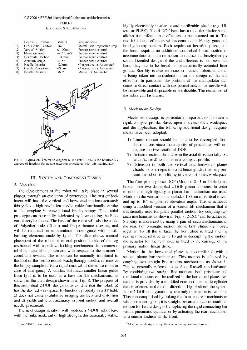
phases, through an evolution of prototypes. The first embod- Motion in the vertical plane includes 100mm of vertical travel,iment will have the vertical and horizontal motions actuated; and up to 100 of positive elevation angle. This is achievedthis yields a high-resolution needle guide functionally similar using a modified version of a scissor lift mechanism that isto the template in conventional brachytherapy. This initial traditionally used for plane parallel motion. By coupling twoprototype can be rapidly fabricated by laser-cutting the links such mechanisms as shown in Fig. 3, 2-DOF can be achieved.out of acrylic sheets. The base of the robot will also be made Stability is increased by using a pair of such mechanisms inof Polyetherimide (Ultem) and Polycarbonate (Lexan), and the rear. For prismatic motion alone, both slides are movedwill be mounted on an aluminum linear guide with plastic together. To tilt the surface, the front slide is fixed and thebushing elements made by Igus'. The slide allows manual rear is moved relative to it. To aid in decoupling the motion,placement of the robot in its end position inside of the leg the actuator for the rear slide is fixed to the carriage of therest/tunnel with a positive locking mechanism that ensures a primary motion linear drive.reliable, repeatable placement with respect to the scanner's Motion in the horizontal plane is accomplished with acoordinate system. The robot can be manually translated to second planar bar mechanism. This motion is achieved bythe foot of the bed to reload brachytherapy needles or remove coupling two straight line motion mechanisms as shown inthe biopsy sample or for a rapid removal of the entire robot in Fig. 4, generally referred to as Scott-Russell mechanisms2.case of emergency. A similar, but much smaller linear guide By combining two straight-line motions, both prismatic andfrom Igus is to be used as a base for the mechanisms, as rotational motions can be realized in the horizontal plane. Ac-shown in the final design shown in in Fig. 8. The purpose of tuation is provided by a modified compact pneumatic cylinderthis simplified 2-DOF design is to validate that the robot: a) that is oriented in the axial direction. Fig. 4 shows the systemhas the desired workspace, b) functions properly in a 3T field, in the 1-DOF configuration where only translation is available.c) does not cause prohibitive imaging artifacts and distortion This is accomplished by linking the front and rear mechanismsand d) yields sufficient accuracy in joint motion and overall with a connecting bar; it is straightforward to add the rotationalneedle placement. motion for future designs by replacing the rigid connecting barThe next design iteration will produce a 4-DOF robot base with a pneumatic cylinder or by actuating the rear mechanism
with the links made out of high strength, dimensionally stable, in a similar fashion as the front.
'Igus NKO2 linear guide 2Mechanism designs - http://www.brockeng.com/mechanism
594
G. S. Fischer, I. lordachita, S. P DiMaio, G. Fichtinger Design of a Robot for Transperineal Prostate Needle Placement in MRI ScannerActuated surface
actuator, or they can be purchased as standard parts from selectElevation companies.
Vertical ................Angle'
.IIll ..... .......i1 ----=; ...... wwll .MM MRS.-D osition Sensing
!1111ii111!.!1111i1i1111!!! !iiii1i!!' . The remaining component of the actuator system is the..sensing element. Standard methods of position sensing that are
suitable for pneumatic cylinders include: linear potentiometers,Sliwade Slide linear variable difrniltransformers (ILVDT), cpctv
Fig. 3. Mechanism design for motion in the vertical plane. Coupling the sensors, ultrasonic sensors, magnetic sensors, laser sensors,forward and rear motion provides for vertical travel, independently moving optical encoders, and cameras (machine vision). Most ofthe rear provides for elevation angle adjustment. these sensing modalities are not practical for use.in.an.MR
t ActuatedTopSurface ~environment. However, there are two methods that do appear__I__I_I__I__I__I_______ll to have potential: 1) linear optical encoders and 2) direct MRI
Horizona C.onneting r image guidMoS ig t eandard optical encoders3 have been tested in a 3tMrI
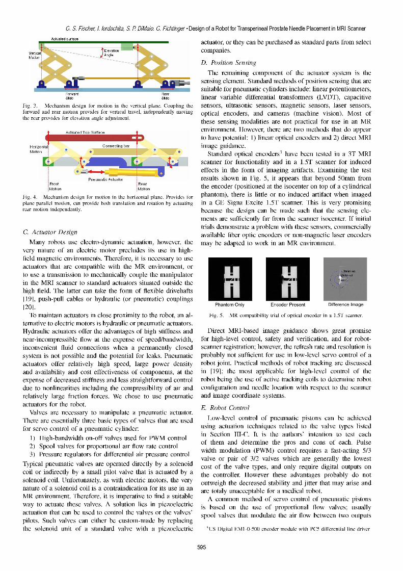
scanner for functionality and in a 1.5T scanner for induced_ it effects in the form of imaging artifacts. Examining the test
q ~~PneumraticActutlaor results shown in Fig. 5, it appears that beyond 50mm from
Fron rRerrth atonr
MotSio Moio eneoder (positionedrnthe isocenter top of caylindricalFig. 4. Mechanism design for motion in the horizontal plane. Provides for phantom), there is little or no induced artifact when imagedplane parallel motion, can provide both translation and rotation by actuating in a GE Signa Excite 1.5T scanner. This is very promisingrear motion independently. because the design can be made such that the sensing ele-
ments are sufficiently far from the scanner isocenter. If initialtrials demonstrate a problem with these sensors, commercially
C.*Actuator Design available fiber optic encoders or non-magnetc laser encodersMany robots use electro-dynamic actuation, however, the may be adapted to work in an MR environment.
very nature of an electric motor precludes its use in high-
fieldmagnenei-nticniomet.thereore it sncsayt usesut hw nFg ,i per htbyn mfo
Tomantainactuatorsthatarecom tibcloewxitotheM iront, oral- (positibilit trisocenteron a candr.tornausvea trasiss moto mechanic oupletmanipcuators.Fin.th MRcIsanns er teostandar actatessorihtuatesotside tence show hen imageplneparallelompresion,ca providatothe expenslainen rtio nsedbyatatingidth, for highleve Ecntrol safetysanner.Tisfisain very forromisin
high fonied Thenlat canntaetin whenfm f lexlenldvehafsce t feshateansin is
[20].m is not possible and the potential for leaks. Pneumatic Phobabyntom sufficientlEforero Pre snt DeisfentceImontiaeT matainnactuators inclos eproxiitynoith robot,aig..Pmompratiblip trole of optic senorsin ac1m5scianer
terndativetelectricya motors isfehydrauli or pneumaoetic acators. ain fibe opt encde or hignevel enodeHdaunli aobctuatseo otiffners aant aes otfaighostifers and DiretbeMR-sed image giancer shows gnreate epromnear-n ofline elestic tcompressibetsflpof aidth, forighelo lstand verification , andhe or robot
stivem ianot psiboneandts.hep hotent fo le pneumatic oab not suffiienat uystei voactuators offer arel elyhig hee, enpowrentyrobot jn P obot
toausesatreansmission to mecanicallyt copleutemanipculator.
andh aieMaIlstyandr tcostanefebsctives of compaoents,aoutsethe ie-level control of theexpeserof dcretaed sffanessandt le straightforwd c o rotuein thsec cives treaci oi toe detyern rbte
dueto onlnerites ncldig te cmpessbilty f ir nd oniguraction and-C needlteloautionswintherespec to thescanerc
r1et vlyh-largle ctionrforaelsWes coseptusem pneuaicoatntaTu)atrfpo tahesoro inBcl RobroCoooltecotrolVernalivesoarelecessaym torsismanipulate a pneumatic actuators.
THereare ssuaetiallythrebasdatypes ofvalvessthtre used L e o f egumdaicpstonscantb achisev
fonearvncontrosilefof wpnuatich cylindeoper:anwith usringh-actuationtechniqufesyreated torficthen,valve type lisoted
vsalecison ho-CIt is thve atho ares' tentrionyotest ieas1y) igh-bndtwit onloefa valveuoted forPeWMs neumaotintrold cos ofthe dufeftyemn thde proy aen e lcons of etach oPus2c Sporo valve s frpraopothioapid flowat p e controlwidthtmodulati(.PrwM cothlsof reutiestr a blfas d 5/3ot
Typavicalbpeumtic valvcst aefoertdfiect lyvbyaesoenoicostnnt,atei of9 the valvetypsandicbl fonl reurhigitaevlcoutputsonh
coilre ofidiectlyedby ianssal o vessralrithatisforctuad bon a r rte controtll useHfoever theseiadanges pedcrob dobnot
solentoi onilUnforituenatly,inaswthe lctmresic oos h ey oteg heraetbility o iand jofgrton edelcto ittersthat may ariesandeneaturelof larsoenoridcoisacnridctionforsWehoet itse pnuse tinca are totagy uncceptablte forsaemedca. obt
MRlvenviro nment.hesaretor inimpuaeratveuatoin acsuitabl A common method of servo control of pneumatc pistonsway to actuate these valves. A solution lies in piezoelectric isgbased ton theiuseo rtional flo valves usual
for srvo cntrolofapneumtic clinde: inSbaetion 111eCuse ofheautors' ntention tolvestesallv
actuation that can be used to control the valves or the valves' X X .d
2)~~~~ ~ ~ ~ ~ ~ ~~~~~~po valvesvalvt modlatprpotheaairflow betw controput
pilots. Such valves can either be custom-made by replacing spool valat moult trfl betwe twootputsthe solenoid unit of a standard valve with a piezoelectric 3US Digital EM1-O-500 encoder module with PC5 differential line driver
595
ICM 2006 * IEEE 3rd International Conference on Mechatronics
corresponding to the two sides of the cylinder being controlled. of the scanner room only include a regulated compressed airThe primary advantage of proportional flow valves is the supply and a fiber optic ethernet connection. High level controlcapability of smooth, high-bandwidth control of the cylinder. an visualization is situated on an RTAI Linux-based laptopA pneumatic control modality that does not appear to PC sitting in the MR console room connected through the
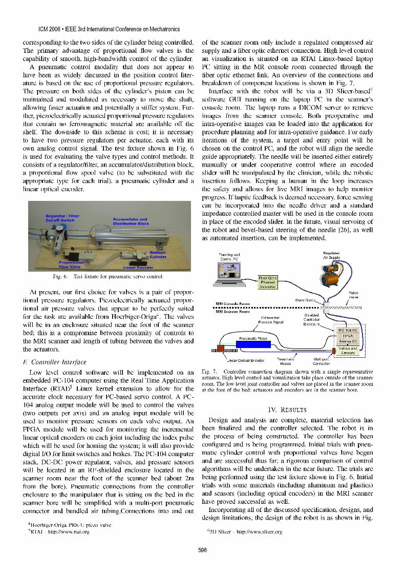
have been as widely discussed in the position control liter- fiber optic ethernet link. An overview of the connections andature is based on the use of proportional pressure regulators. breakdown of component locations is shown in Fig. 7.The pressure on both sides of the cylinder's piston can be Interface with the robot will be via a 3D Slicer-based6maintained and modulated as necessary to move the shaft, software GUI running on the laptop PC in the scanner'sallowing faster actuation and potentially a stiffer system. Fur- console room. The laptop runs a DICOM server to retrievether, piezoelectrically actuated proportional pressure regulators images from the scanner console. Both preoperative andthat contain no ferromagnetic material are available off the intra-operative images can be loaded into the application forshelf. The downside to this scheme is cost; it is necessary procedure planning and for intra-operative guidance. For earlyto have two pressure regulators per actuator, each with its iterations of the system, a target and entry point will beown analog control signal. The test fixture shown in Fig. 6 chosen on the control PC, and the robot will align the needleis used for evaluating the valve types and control methods. It guide appropriately. The needle will be inserted either entirelyconsists of a regulator/filter, an accumulator/distribution block, manually or under cooperative control where an encodeda proportional flow spool valve (to be substituted with the slider will be manipulated by the clinician, while the roboticappropriate type for each trial), a pneumatic cylinder and a insertion follows. Keeping a human in the loop increaseslinear optical encoder. the safety and allows for live MRI images to help monitor
progress. If haptic feedback is deemed necessary, force sensingcan be incorporated into the needle driver and a standardimpedance controlled master will be used in the console roomin place of the encoded slider. In the future, visual servoing ofthe robot and bevel-based steering of the needle [26], as wellas automated insertion, can be implemented.
Planning and RegulatedControl PC ArSpl
Fig. 6. Test fixture for pneumatic servo control. FQp)
At present, our first choice for valves is a pair of propor- oh
tional pressure regulators. Piezoelectrically actuated propor- MConsoleRoom Guide l
tional air pressure valves that appear to be perfectly suited MRIScaer Roomfor the task are available from Hoerbiger-Origa4. The valves Differehtial Shielde
will be in an enclosure situated near the foot of the scanner Encoder Signal Enclosure - -bed; this is a compromise between proximity of controls tothe MRI scanner and length of tubing between the valves and P P Aa_ I/Ethe actuators.
Linear Optical Encoder Pneumatic Multi_potF Controller Interface Hoses Connedor
Low level control software will be implemented on an Fig. 7. Controller connection diagram shown with a single representativeembedded PC- 104 computer using the Real Time Application actuator. High level control and visualization take place outside of the scanner
room. The low level joint controller and valves are placed in the scanner roomInterface (RTAI)5 Linux kernel extension to allow for the at the foot of the bed; actuators and encoders are in the scanner bore.accurate clock necessary for PC-based servo control. A PC-104 analog output module will be used to control the valves(two outputs per axis) and an analog input module will be IV. RESULTSused to monitor pressure sensors on each valve output. An Design and analysis are complete, material selection hasFPGA module will be used for monitoring the incremental been finalized and the controller selected. The robot is inlinear optical encoders on each joint including the index pulse the process of being constructed. The controller has beenwhich will be used for homing the system; it will also provide configured and is being programmed. Initial trials with pneu-digital I/O for limit switches and brakes. The PC- 104 computer matic cylinder control with proportional valves have begunstack, DC-DC power regulator, valves, and pressure sensors and are successful thus far; a rigorous comparison of controlwill be located in an RF-shielded enclosure located in the algorithms will be undertaken in the near future. The trials arescanner room near the foot of the scanner bed (about 2m being performed using the test fixture shown in Fig. 6. Initialfrom the bore). Pneumatic connections from the controller trials with some materials (including aluminum and plastics)enclosure to the manipulator that is sitting on the bed in the and sensors (including optical encoders) in the MRI scannerscanner bore will be simplified with a multi-port pneumatic have proved successful as well.connector and bundled air tubing.Connections into and out Incorporating all of the discussed specification, designs, and
design limitations, the design of the robot is as shown in Fig.4Hoerbiger-Origa PRE-U piezo valve5RTAI - http://www.rtai.org 63D Slicer - http://www.slicer.org
596
G. S. Fischer, I. lordachita, S. P DiMaio, G. Fichtinger Design of a Robot for Transperineal Prostate Needle Placement in MRI Scanner
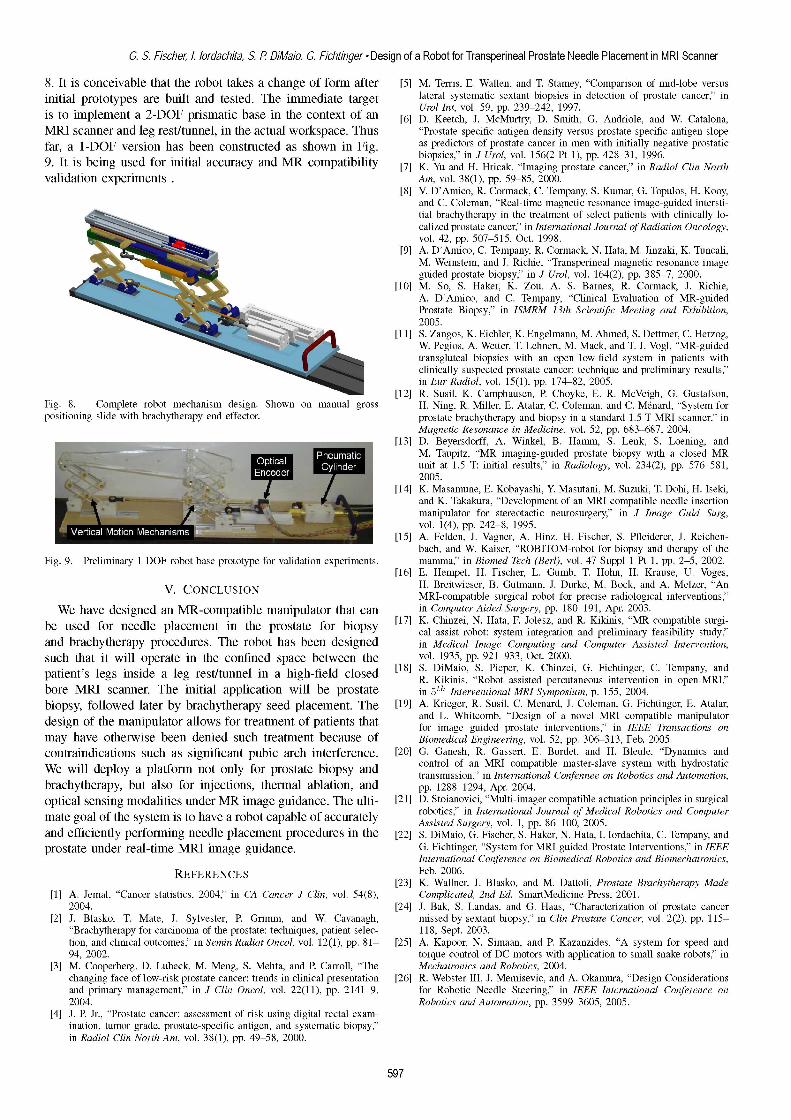
8. It is conceivable that the robot takes a change of form after [5] M. Terris, E. Wallen, and T. Stamey, "Comparison of mid-lobe versusinitial prototypes are built and tested. The immediate target lateral systematic sextant biopsies in detection of prostate cancer," inis to implement a 2-DOF prismatic base in the context of an [6] Urol Int, vol. 59, pp. 239-242, 1997.
[6] D. Keetch, J. McMurtry, D. Smith, G. Andriole, and W. Catalona,MRI scanner and leg rest/tunnel, in the actual workspace. Thus "Prostate specific antigen density versus prostate specific antigen slopefar, a 1-DOF version has been constructed as shown in Fig. as predictors of prostate cancer in men with initially negative prostatic
9. It s bein used or iniial acuracy nd MR ompatiility biopsies," in J Urol, vol. 156(2 Pt 1), pp. 428-31, 1996.9. It is being used for initial accuracy and MR compatibility biop-'[7]K. Yu and H. Hricak, "Imaging prostate cancer," in Radiol Clin Northvalidation experiments Am, vol. 38(1), pp. 59-85, 2000.
[8] V. D'Amico, R. Cormack, C. Tempany, S. Kumar, G. Topulos, H. Kooy,and C. Coleman, "Real-time magnetic resonance image-guided intersti-tial brachytherapy in the treatment of select patients with clinically lo-calized prostate cancer," in International Journal of Radiation Oncology,vol. 42, pp. 507-515, Oct. 1998.
[9] A. D'Amico, C. Tempany, R. Cormack, N. Hata, M. Jinzaki, K. Tuncali,M. Weinstein, and J. Richie, "Transperineal magnetic resonance imageguided prostate biopsy," in J Urol, vol. 164(2), pp. 385-7, 2000.
[10] M. So, S. Haker, K. Zou, A. S. Barnes, R. Cormack, J. Richie,A. D'Amico, and C. Tempany, "Clinical Evaluation of MR-guidedProstate Biopsy," in ISMRM 13th Scientifc Meeting and Exhibition,2005.
[11] 5. Zangos, K. Eichler, K. Engelmann, M. Ahmed, S. Dettmer, C. Herzog,W. Pegios, A. Wetter, T. Lehnert, M. Mack, and T. J. Vogl, "MR-guidedtransgluteal biopsies with an open low-field system in patients withclinically suspected prostate cancer: technique and preliminary results,"in Eur Radiol, vol. 15(1), pp. 174-82, 2005.
[12] R. Susil, K. Camphausen, P. Choyke, E. R. McVeigh, G. Gustafson,Fig. 8. Complete robot mechanism design. Shown on manual gross H. Ning, R. Miller, E. Atalar, C. Coleman, and C. M6nard, "System forpositioning slide with brachytherapy end effector. prostate brachytherapy and biopsy in a standard 1.5 T MRI scanner," in
Magnetic Resonance in Medicine, vol. 52, pp. 683-687, 2004.[13] D. Beyersdorff, A. Winkel, B. Hamm, S. Lenk, S. Loening, and[3M. Taupitz, "MR imaging-guided prostate biopsy with a closed MR
- ~~~unit at 1.5 T: initial results," in Radiology, vol. 234(2), pp. 576-581,2005.
[14] K. Masamune, E. Kobayashi, Y Masutani, M. Suzuki, T. Dohi, H. Iseki,and K. Takakura, "Development of an MRI-compatible needle insertionmanipulator for stereotactic neurosurgery," in J Image Guid Surg,vol. 1(4), pp. 242-8, 1995.
[15] A. Felden, J. Vagner, A. Hinz, H. Fischer, S. Pfleiderer, J. Reichen-bach, and W. Kaiser, "ROBITOM-robot for biopsy and therapy of the
Fig. 9. Preliminary 1-DOF robot base prototype for validation experiments. mamma," in Biomed Tech (Berl), vol. 47 Suppl 1 Pt 1, pp. 2-5, 2002.[16] E. Hempel, H. Fischer, L. Gumb, T. Hohn, H. Krause, U. Voges,
V CONCLUSION H. Breitwieser, B. Gutmann, J. Durke, M. Bock, and A. Melzer, "AnMRI-compatible surgical robot for precise radiological interventions,"
We have designed an MR-compatible manipulator that can in Computer Aided Surgery, pp. 180-191, Apr. 2003.be used for needle placement in the prostate for biopsy [17] K. Chinzei, N. Hata, F. Jolesz, and R. Kikinis, "MR compatible surgi-
cal assist robot: system integration and preliminary feasibility study,"and brachytherapy procedures. The robot has been designed in Medical Image Computing and Computer Assisted Intervention,such that it will operate in the confined space between the vol. 1935, pp. 921-933, Oct. 2000.patient's legs inside a leg rest/tunnel in a high-field closed [18] s. DiMaio, S. Pieper, K. Chinzei, G. Fichtinger, C. Tempany, and
R. Kikinis, "Robot assisted percutaneous intervention in open-MRI,"bore MRI scanner. The initial application will be prostate in 5th Interventional MRI Symposium, p. 155, 2004.biopsy, followed later by brachytherapy seed placement. The [19] A. Krieger, R. Susil, C. Menard, J. Coleman, G. Fichtinger, E. Atalar,
of the manipulator allows for treatment of patients that and L. Whitcomb, "Design of a novel MRI compatible manipulatordesign of he anlulaor llos fr teatentOI ahets hat for image guided prostate interventions," in IEEE Transactions onmay have otherwise been denied such treatment because of Biomedical Engineering, vol. 52, pp. 306-313, Feb. 2005.contraindications such as significant pubic arch interference. [20] G. Ganesh, R. Gassert, E. Burdet, and H. Bleule, "Dynamics andWe will deploy a platform not only for prostate biopsy and control of an MRI compatible master-slave system with hydrostatic
transmission," in International Confennee on Robotics and Automation,brachytherapy, but also for injections, thermal ablation, and pp. 1288-1294, Apr. 2004.optical sensing modalities under MR image guidance. The ulti- [21] D. Stoianovici, "Multi-imager compatible actuation principles in surgical
of the system is to have a robot capable of accurately robotics," in International Journal of Medical Robotics and Computermate goal of the system 1S to have a roDot capaDle OI accurately Assisted Surgery, vol. 1, pp. 86-100, 2005.and efficiently performing needle placement procedures in the [22] S. DiMaio, G. Fischer, S. Haker, N. Hata, I. lordachita, C. Tempany, andprostate under real-time MRI image guidance. G. Fichtinger, "System for MRI-guided Prostate Interventions," in IEEE
International Conference on Biomedical Robotics and Biomechatronics,REFERENCES Feb. 2006.
[23] K. Wallner, J. Blasko, and M. Dattoli, Prostate Brachytherapy Made[1] A. Jemal, "Cancer statistics, 2004," in CA Cancer J Clin, vol. 54(8), Complicated, 2nd Ed. SmartMedicine Press, 2001.
2004. [24] J. Bak, S. Landas, and G. Haas, "Characterization of prostate cancer[2] J. Blasko, T. Mate, J. Sylvester, P. Grimm, and W. Cavanagh, missed by sextant biopsy," in Clin Prostate Cancer, vol. 2(2), pp. 115-
"Brachytherapy for carcinoma of the prostate: techniques, patient selec- 118, Sept. 2003.tion, and clinical outcomes," in Semin Radiat Oncol, vol. 12(1), pp. 81- [25] A. Kapoor, N. Simaan, and P. Kazanzides, "A system for speed and94, 2002. torque control of DC motors with application to small snake robots," in
[3] M. Cooperberg, D. Lubeck, M. Meng, S. Mehta, and P. Carroll, "The Mechatronics and Robotics, 2004.changing face of low-risk prostate cancer: trends in clinical presentation [26] R. Webster III, J. Memisevic, and A. Okamura, "Design Considerationsand primary management," in J Clin Oncol, vol. 22(11), pp. 2141-9, for Robotic Needle Steering," in IEEE International Conference on2004. Robotics and Automation, pp. 3599-3605, 2005.
[4] J. P. Jr., "Prostate cancer: assessment of risk using digital rectal exam-ination, tumor grade, prostate-specific antigen, and systematic biopsy,"in Radiol Clin North Am, vol. 38(1), pp. 49-58, 2000.
597