design rationale - biomet design rational.pdf · 1 a round sagittal profi le as found in the...
TRANSCRIPT
DESIGN RATIONALE
INTRODUCTION Beginning with the AGC® and continuing with the Maxim® and Ascent,™ Biomet’s total knee systems have a long and rich clinical heritage. With the introduction of the Vanguard™ Complete Knee System, Biomet has taken this proven clinical heritage and combined it with state-of-the-art design features to produce the most comprehensive total knee system available. With the introduction of Microplasty® and Premier™ instrumentation platforms and advancements such as our patented Slidex® Technology, the Vanguard™ Complete Knee System is the surgeon’s ally in exceeding the demands of today’s active joint replacement patient.
ADVANCING TECHNOLOGY When designing the Vanguard™ Complete Knee System, every feature in the femur, patella and tibia was reviewed for potential performance enhancement in all patient populations. Many clinically successful features found in earlier Biomet® total knee systems remain the same in the Vanguard™ Complete Knee System. However, many more features were added.
Patella/Femoral JointThe Vanguard™ femoral component has four main design features incorporated into the sagittal profi le:
• Rounded sagittal profi le
• Deeper, swept-back trochlear groove
• Longer trochlear groove
• Wide proximal trochlear groove
Each of these variables improves lateral release rates, extensor moment arm, patella alignment and patella tracking, while reducing the potential for patellar tendon irritation.
Rounded Sagittal Profi leTwo distinct femoral designs have evolved over time: an anatomic (box-like) femoral profi le and a more swept-back (rounder) sagittal profi le.
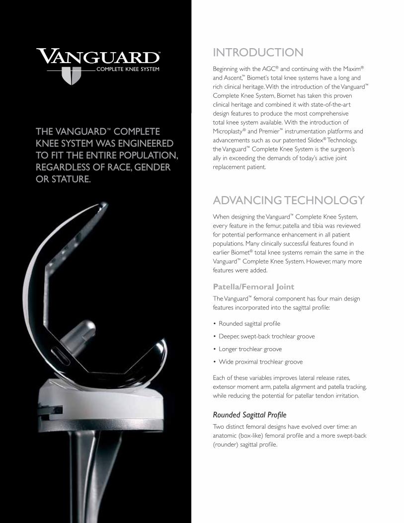
THETHE VANGUARDVANGUARD™ COMPLETE COMPLETE KNEE SYSTEMKNEE SYSTEM WAS ENGINEERED WAS ENGINEERED TO FITTO FIT THE ENTIRE POPULATION, THE ENTIRE POPULATION, REGARDLESS OF RACE, GENDER REGARDLESS OF RACE, GENDER OR STATURE.OR STATURE.

1
A round sagittal profi le as found in the Vanguard™ knee may be more forgiving to the retinaculum by not over tensioning the soft tissues.
Deeper/Swept-back Trochlear GrooveThe trochlear groove is a critical design feature for patella performance. Translation of the trochlear groove posteriorly in the femur has shown to resist patella crepitus and clunk.1 The Vanguard™ trochlear groove has been designed to sweep back posteriorly for better patellar performance.
Longer Trochlear GrooveThe trochlear groove has also been lengthened to further support the patella in deep fl exion. This longer trochlear groove also better supports the quadriceps tendon. In deep fl exion, a shorter trochlear groove, as in the Maxim® knee, will articulate on the quadriceps tendon at the junction of the trochleargroove and posterior stabilized (PS) box at 75 to 80 degrees of fl exion. In the Vanguard™ knee, the junction does not articulate with the quadriceps tendon until 105 to 120 degrees of fl exion.
Wider Proximal Trochlear GroovePatellar capture during fl exion must be balanced with the need for less patellar constraint in extension. The Vanguard™ knee provides for this balance through a widened trochlear fl oor to reduce constraining forces in extension and a 6.5 degree valgus angulation of the patella track. “Valgus angulation has been shown to reduce the patellar shear stresses.”2
In addition to a wider proximal trochlear groove, the Vanguard™ knee offers a comprehensive approach to patellofemoral mechanics that includes femoral retinacular relief, a lateralized trochlea and a clinically proven dome patellar component. The aggregate of these features produces a component that provides for excellent patellar tracking (within 0–15 degrees of valgus) regardless of the patient’s Q-angle.3 Retinacular relief minimizes soft tissue tension, reducing the potential need for a lateral release.
The narrow anterior fl ange maintains a small profi le to reduce the likelihood of femoral overhang. To further address overhang, the Vanguard™ knee features rounded corners on the anterior fl ange. Proper femoral fi t with respect to overhang is a primary concern for patients with smaller anatomies, most commonly found in the female population. The Vanguard™ knee addresses this by offering a femoral component that grows medial/lateral in 2.4mm increments between its smallest six sizes, which have shown to be the most commonly utilized sizes for female patients.
Anatomic (Gold) vs. Swept-back (Gray) Sagittal Profi le
Deeper and Longer Trochlear Groove (Gray)
Standard Trochlear Groove (Gold)
Most Commonly Used Femoral Sizes Based on 1,611 Vanguard™ Knees Implanted in Females3
30
20
10
0
Size 55
% o
f Fem
ales
Size 57.5Size 60
Size 62.5Size 65
Size 67.5Size 70
Size 72.5Size 75
Size 80
0–15°
Q-angle

2
Articulation Features
Coronal Geometry FeaturesThe Vanguard™ knee system provides a fully congruent (coronally), moderately dished articulation, which reduces polyethylene stresses while still allowing physiological motion. The patented 1:1 condylar geometry provides surgical fl exibility by allowing tibial-femoral interchangeability.
The Vanguard™ cruciate retaining (CR) and posterior stabilized (PS) femurs have complete size interchangeability with their respective primary bearings.*
To increase contact area with axial rotation, the Vanguard™ knee features a rotated bearing surface articulation. As compared to a linear articulation, a rotated articulation increases the contact area by 13 percent.3
Increased Range of MotionThe Vanguard™ knee has been designed to accommodate patients who require an above average range of motion. The femoral posterior condyle geometry will allow for 145 degrees of fl exion. The Vanguard™ knee is able to achieve this high range of motion without the need to resect an additional 2mm of posterior condyles. The Vanguard™ tibial bearings have a deeper anterior relief to minimize the potential for patella impingement during high fl exion.
Proportional Posterior CondylesThe posterior condyles grow proportionally in size. This provides better bone coverage and reduces overstuffi ng the fl exion gap in smaller femurs or undersizing the posterior condyles in larger femurs. Better coverage of the posterior condyles aids in achieving high fl exion and restoring femoral offset.
The posterior condyle geometry has also been optimized to provide larger contact areas in deep fl exion. Larger contact areas will dissipate forces more effectively.4
145 Degrees Range of Motion with Primary Bone Cuts
Finite Element Analysis Demonstrates a Gradual Dispersion of Forces Along the Patella3
Rotated Tibial Articulating Surface
High Flexion Patellar Tendon Relief
1:1 Tibial -Femoral Contact
*With the exception of the Vanguard™ Anterior Stabilized (AS) Bearing.
The coronal geometry features a softened intercondylar (medial and lateral) edge. This radius enhancement produces increased contact area for the patella when articulating on the condyles in fusion. Finite element analysis has demonstrated a 25 percent reduction in patella contact pressure compared to the Maxim® Total Knee design.3
3
Intermediate Femoral SizesThe Vanguard™ knee has introduced four additional intermediate sized primary femoral components to enhance the traditional femoral offering.
Ten Vanguard™ femoral component sizes, combined with nine Vanguard™ tibial component sizes, while maintaining complete interchangeability among all sizes, provide intraoperative fl exibility to fi t varying patient anatomies of both the femur and the tibia independently. The end result is a complete knee system that is the most fl exible on the market, allowing a custom fi t for the entire population, regardless of race, gender or stature.
Specifi c Posterior Stabilized Design FeaturesA multitude of design features affect the performance of a cam and spine type of posterior stabilized knee. The following design features are key elements in the Vanguard™ PS system:
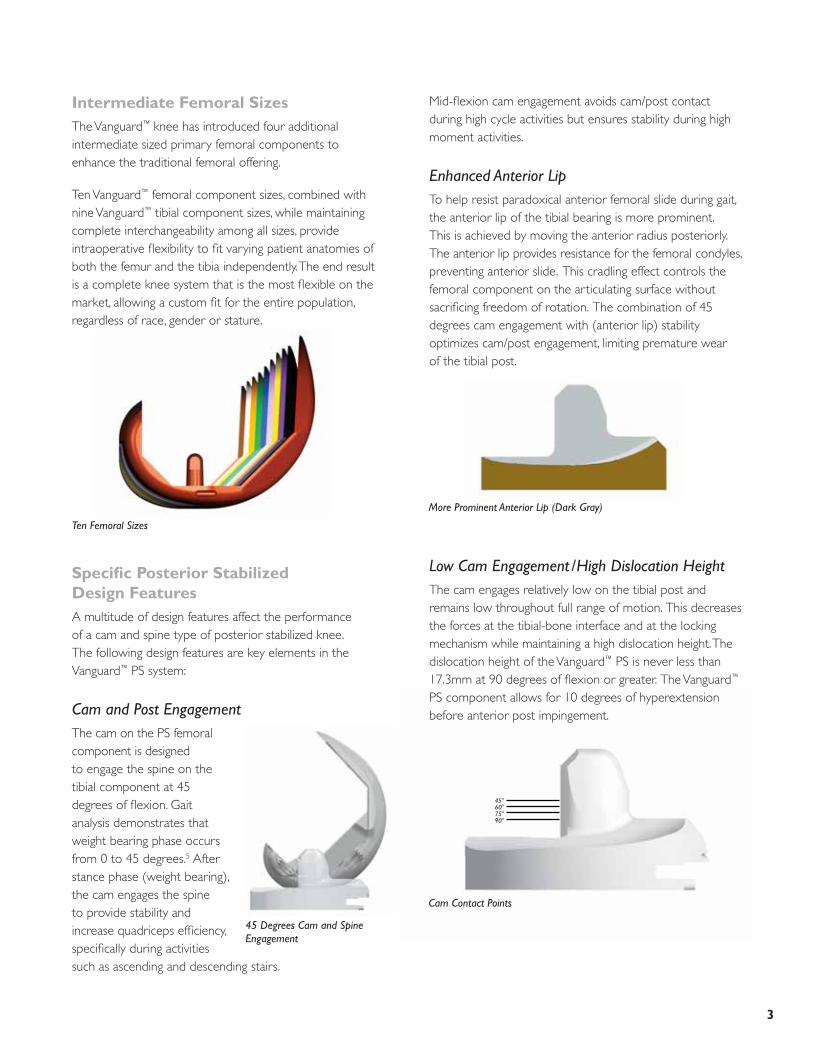
Cam and Post EngagementThe cam on the PS femoral component is designed to engage the spine on the tibial component at 45 degrees of fl exion. Gait analysis demonstrates that weight bearing phase occurs from 0 to 45 degrees.5 After stance phase (weight bearing), the cam engages the spine to provide stability and increase quadriceps effi ciency, specifi cally during activities such as ascending and descending stairs.
Ten Femoral Sizes
Cam Contact Points
45°60°75°90°
Mid-fl exion cam engagement avoids cam/post contact during high cycle activities but ensures stability during high moment activities.
Enhanced Anterior LipTo help resist paradoxical anterior femoral slide during gait, the anterior lip of the tibial bearing is more prominent. This is achieved by moving the anterior radius posteriorly. The anterior lip provides resistance for the femoral condyles, preventing anterior slide. This cradling effect controls the femoral component on the articulating surface without sacrifi cing freedom of rotation. The combination of 45 degrees cam engagement with (anterior lip) stability optimizes cam/post engagement, limiting premature wear of the tibial post.
Low Cam Engagement/High Dislocation HeightThe cam engages relatively low on the tibial post and remains low throughout full range of motion. This decreases the forces at the tibial-bone interface and at the locking mechanism while maintaining a high dislocation height. The dislocation height of the Vanguard™ PS is never less than 17.3mm at 90 degrees of fl exion or greater. The Vanguard™ PS component allows for 10 degrees of hyperextension before anterior post impingement.
45 Degrees Cam and Spine Engagement
More Prominent Anterior Lip (Dark Gray)
4
Premier™ PS Femoral Mill Box Resection
Square Corner
Round Corner
Finite Element Analysis Demonstrating Lower Concentration of Stress at Corner of Box
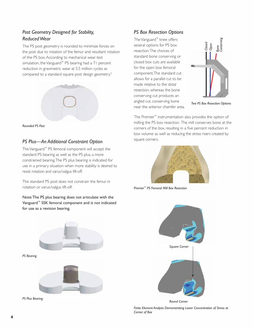
Post Geometry Designed for Stability, Reduced WearThe PS post geometry is rounded to minimize forces on the post due to rotation of the femur and resultant rotation of the PS box. According to mechanical wear test simulation, the Vanguard™ PS bearing had a 71 percent reduction in gravimetric wear at 5.5 million cycles as compared to a standard square post design geometry.3
PS Plus—An Additional Constraint OptionThe Vanguard™ PS femoral component will accept the standard PS bearing as well as the PS plus, a more constrained bearing. The PS plus bearing is indicated for use in a primary situation when more stability is desired to resist rotation and varus/valgus lift-off.
The standard PS post does not constrain the femur in rotation or varus/valgus lift-off.
Note: The PS plus bearing does not articulate with the Vanguard™ SSK femoral component and is not indicated for use as a revision bearing.
PS Box Resection OptionsThe Vanguard™ knee offers several options for PS box resection. The choices of standard bone conserving or closed box cuts are available for the open box femoral component. The standard cut allows for a parallel cut to be made relative to the distal resection, whereas the bone conserving cut produces an angled cut, conserving bone near the anterior chamfer area.
The Premier™ instrumentation also provides the option of milling the PS box resection. The mill conserves bone at the corners of the box, resulting in a fi ve percent reduction in box volume as well as reducing the stress risers created by square corners.
PS Bearing
PS Plus Bearing
Rounded PS Post
Two PS Box Resection Options
Clos
edO
pen
Bone
Co
nser
ving

5
Specifi c Cruciate Retaining Design FeaturesThe Vanguard™ CR femoral component incorporates all design and articulation features of the posterior stabilized design as well as key features specifi c to the CR femoral component.
Removable Femoral LugsThe femoral lugs on the Vanguard™ CR are removable. This feature allows for augmentation if required in primary total knee arthroplasty or in the revision of a failed unicompartmental knee arthroplasty.
Two Fixation OptionsThe Vanguard™ CR and PS femoral components are available in two fi xation options: Interlok® roughened fi nish for cement fi xation or PPS® Porous Plasma Spray Coating for cementless fi xation.
The Vanguard™ CR and PS porous options have been cleared by the FDA for cementless fi xation.
Cruciate Retaining Bearing OptionsThe options for tibial bearings include standard (with three degrees posterior slope built into the articulating surface), posterior lipped and anterior stabilized.
Removable CR Lugs
Augment Attached to CR Knee
CR Lipped (No Slope)
Anterior Stabilized Bearing (No Slope)
Standard CR (Three-Degrees Posterior Slope)
These options provide a multitude of choices to meet patient needs and surgeon preferences.

6
Specifi c Vanguard™ SSK Revision Femoral Design FeaturesWhile the Vanguard™ SSK femoral component integrates all the primary femoral component design features, there are a few differentiating design features specifi c to the Vanguard™ SSK revision femoral component.
SSK Bearing OptionsThe Vanguard™ SSK revision system offers two bearing options: the SSK PS tibial bearing and the SSK constrained tibial bearing. This feature allows the surgeon intraoperative fl exibility in the case of collateral defi ciencies.
The SSK PS bearing provides only posterior stabilization with the Vanguard™ SSK revision femur.
The SSK constrained bearing is designed to allow for +/-1 degree of varus/valgus lift-off and +/-0.5 degree of rotational freedom.
SSK Femoral Component
SSK PS Bearing and SSK Constrained Bearing
StabilityThe SSK constrained bearing offers a large swept back tibial post that provides stability and continued constraint in deep fl exion. The large tibial post also maintains increased post /box contact. At 90 degrees of fl exion, 17mm of the post remains in the box.
SSK Femoral Component Extended CamThe Vanguard™ SSK femoral component adds an additional 3mm of material on the cam. This provides for a higher dislocation height, up to 23mm, prior to dislocation.
Stem Boss AngleThe Vanguard™ SSK femur has a fi ve-degree stem valgus angle which will accept multiple stem lengths in straight and curved profi les to match the patient’s anatomy.
SSK Tibial Post in Box
Extended Cam
Stem Boss Angle

7
Oxidation may negatively impact the fatigue characteristics of the polyethylene, causing delamination.
Biomet was the fi rst company to use an inert gas, argon, to replace oxygen during the sterilization and packaging processes. The use of argon reduces the degradative effects of oxygen present in polyethylene-bearing designs. Furthermore, gamma sterilization in an argon atmosphere has been shown to decrease wear over EtO sterilized polyethylene by 44 percent.15 ArCom® polyethylene has been clinically proven to be more resistant to wear, delamination and oxidation.16–19
Polyethylene Thickness/Locking Mechanism DesignMeding, et al. demonstrated excellent long-term results with 4.4mm minimum thickness Direct Compression Molded tibial bearings.7 The Vanguard™ knee system provides a minimum of 6mm of polyethylene thickness in its primary, posterior stabilized and revision components. Thicknesses for all polyethylene sizes are listed in the polyethylene size/thickness chart.
CLINICAL HERITAGEArCom® PolyethyleneBiomet has made the commitment to Direct Compression Mold all tibial bearings* within the Vanguard™ system to minimize the potential for wear and oxidative breakdown. Biomet’s ability to combine clinically proven polyethylene6–10 with the Vanguard™ knee system punctuates Biomet’s engineering-driven approach. Knee wear is thought to predominately be a fatigue mechanism, which may lead to delamination and pitting of the bearing surface. Traditional machining of tibial articulations has been shown to be detrimental to the long-term performance of knee replacements.11–14 The cutting tools used in machining shear the polyethylene and pull the material apart, creating regions of residual stress. This residual stress may sensitize the material to localized breakdown and oxidation.
+
+
=
=
Extruded Bar Stock Machining Oxidized Cross-Section
Resin Direct Molding Non-Oxidized Cross-Section
Femoral AugmentationIndividual distal (5mm, 10mm and 15mm thicknesses) and posterior (5mm and 10mm thicknesses) augmentation blocks are available for patients with inadequate bone stock.
Augments
Wear Testing
15mm5mm
10mm
10mm
5mm
Polyethylene Size/Thickness
Size 10 12 14 16 18 20 22 24 Thickness
Polyethylene Articulating 6 8 10 12 14 16 18 20 Thickness(mm)
*May not be applicable to custom products.

8
Achieving Optimal Bone CoverageThe Vanguard™ femoral components are based on extensive cadaver studies. Mensch and Amstutz27 reviewed 200 cadaver knees which served as the basis of AGC,® Maxim® and Vanguard™ femoral component sizing. Four additional sizes are offered with the Vanguard™ system, reducing the interval between sizes in the center of the usage distribution.
Biomet Tibial Plate Sizing
Micro Macro Macro
M/L 59 63 67 71 75 79 83 87 91
A/P 38 41 43 46 48 51 53 56 58
Mensch and Amstutz Tibial Sizing27
Bell Curve of Femoral Coverage with Additional Intermediate Sizes
Effective polyethylene thickness is determined by evaluating not only thickness at the center of the tibial condyle but also by measuring the periphery of the polyethylene insert. Many currently manufactured components provide adequate thickness at the center but compromise thickness around the edges due to the design of the locking mechanism. Feng, et al. have found that the most severe polyethylene wear occurs at the periphery, where the component had a raised metal edge.20 These concerns have been addressed in the Biomet modular tibial trays. The peripheral polyethylene thickness is maintained by locating the locking mechanism anteriorly and within the intercondylar area. Concerns have been raised about modularity and bearing micromotion as a contributor to osteolysis and early failure.21–26 Biomet’s locking mechanism compresses the polyethylene bearing against the tray, thereby reducing micromotion. Published literature has also shown the Biomet® locking mechanism to be the most stable overall.22,23
Tibial Tray SizingMany knee systems offer a variety of tibial tray sizes. However, few systems offer consistent, close sizing. The Vanguard™ knee system offers nine tibial sizes that change in consistent 4mm M/L intervals, based on the work of Mensch and Amstutz.27 A scientifi c study was conducted that examined eight tibial tray designs, six symmetrical and two asymmetrical.28 Incavo, et al. showed that the sizing rationale for the AGC® Total Knee System, which is closely paralleled by the Vanguard™ system, offers optimal coverage as compared to competitive asymmetrical designs. Of all the tibial trays tested, the AGC® knee was ranked as the best in total coverage, covering 80.8 percent of the tibial surface.28
Anterior Compressive Locking Mechanism

9
Interlok® Finish
Patellar ArticulationRitter, Lombardi, Insall, Ranawat and others have shown excellent long-term results with domed patellar designs.6,8,29–31 The domed patella is more forgiving in placement than other designs and can more reliably provide congruent contact.
Series A Patellas The Vanguard™ total knee system offers multiple patella options. Patellas are available in one and three peg options in standard thicknesses and in a thinner version which is on average 1.5mm thinner than the standard patella.
Component FixationThe Vanguard™ knee system incorporates two types of fi xation fi nishes. The Interlok® fi nish allows for proper cement interdigitation into the surface for a more
secure bond.
Series A Standard One and Three Peg Patellas
Domed PatellaSince its introduction in 1981, Biomet’s PPS® Porous Plasma Spray Coating has been used by surgeons throughout the world to achieve better fi xation on a multitude of products including the AGC® knee, Maxim® knee, Ascent™ knee, Taperloc® hip, and Bio-Modular® total shoulder. At follow-up, surgeons are observing extremely low rates of osteolysis and nearly 100 percent survivorship at over 10 years with PPS® coating prostheses.32–35
PPS® Coating
10
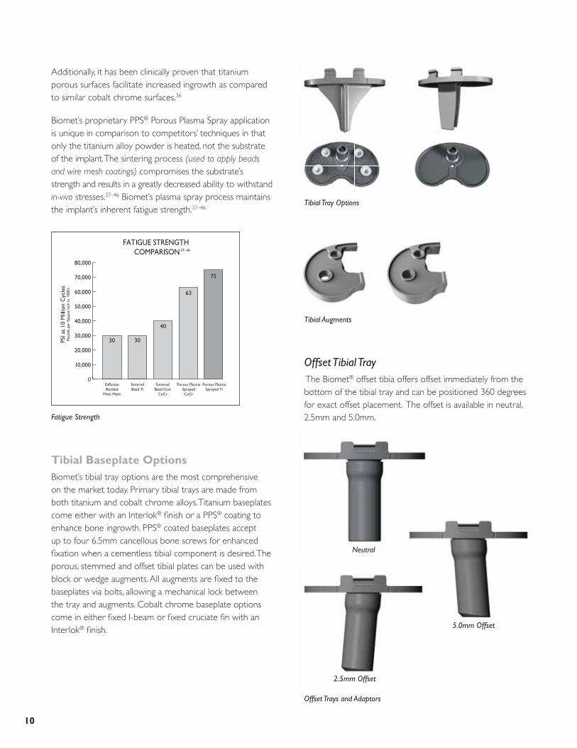
Offset Tibial Tray The Biomet® offset tibia offers offset immediately from the bottom of the tibial tray and can be positioned 360 degrees for exact offset placement. The offset is available in neutral, 2.5mm and 5.0mm.
Tibial Tray Options
Additionally, it has been clinically proven that titanium porous surfaces facilitate increased ingrowth as compared to similar cobalt chrome surfaces.36
Biomet’s proprietary PPS® Porous Plasma Spray application is unique in comparison to competitors’ techniques in that only the titanium alloy powder is heated, not the substrate of the implant. The sintering process (used to apply beads and wire mesh coatings) compromises the substrate’s strength and results in a greatly decreased ability to withstand in-vivo stresses.37–46 Biomet’s plasma spray process maintains the implant’s inherent fatigue strength.37–46
Tibial Baseplate OptionsBiomet’s tibial tray options are the most comprehensive on the market today. Primary tibial trays are made from both titanium and cobalt chrome alloys. Titanium baseplates come either with an Interlok® fi nish or a PPS® coating to enhance bone ingrowth. PPS® coated baseplates accept up to four 6.5mm cancellous bone screws for enhanced fi xation when a cementless tibial component is desired. The porous, stemmed and offset tibial plates can be used with block or wedge augments. All augments are fi xed to the baseplates via bolts, allowing a mechanical lock between the tray and augments. Cobalt chrome baseplate options come in either fi xed I-beam or fi xed cruciate fi n with an Interlok® fi nish.
Fatigue Strength
Offset Trays and Adaptors
Tibial Augments
Neutral
5.0mm Offset
2.5mm Offset

11
Stem OptionsThe modular primary tray provides for the intraoperative selection of the stem to match the specifi c needs of the patient. The combination of a Morse-type taper and screw fi xation helps maintain a solid connection between the stem and plate. When more fi xation is desired, the stemmed tray or offset tray will accept stem extensions.
Stem Extensions
Modular Tibial Tray Stems

12
REFERENCES 1. Ip, D. et al. Comparison of two total knee prostheses on the incidence of patella
clunk syndrome. International Orthopaedics. 26(1): 48–51, 2002.
2. Peterslidge, W.J. et al. The Effect of Trochlear Design on Patellofemoral Shear and Compressive Forces in Total Knee Arthroplasty. Clinical Orthopaedics and Related Research. 309: 136–45, 1994.
3. Data on fi le at Biomet.*
4. Bartel, D.L. et al. The Effect of Conformity, Thickness, and Material on Stresses in Ultra-High Molecular Weight Components for Total Joint Replacement. Journal of Bone and Joint Surgery. 68-A(7): 1041, 1986.
5. Banks, S.A. et al. Function of Total Knee Replacements During Activities of Daily Living. Scientifi c Exhibit at AAOS, Orlando, Florida, 2000.
6. Ritter, M. et al. Long-Term Followup of Anatomic Graduated Cruciate-Retaining Total Knee Replacement. Clinical Orthopaedics and Related Research. 388: 51–57, 2001.
7. Meding, J. et al. Total Knee Arthroplasty with 4.4mm of Tibial Polyethylene. Clinical Orthopaedics and Related Research. 388: 112–117, 2001.
8. Robertson, O. et al. The Swedish Knee Arthroplasty Register, A Nation-Wide Study of 30,003 Knees 1976–1992, Department of Orthopaedics, University Hospital, Lund, Sweden. Acta Orthopaedica Scandanavica. 65: 375–386, 1994.
9. Paavolainen, P. Long-Term Results of Total Joint Arthroplasty. Results of a 15 year follow-up on a nationwide registration programme in Finland with 67,714 TJA’s. National Agency for Medicines Medical Device Center. 1–11, 1994.
10. Emerson, R. Higgins, L. Head, W. The AGC® Total Knee Prosthesis at Average 11 Years. Journal of Arthroplasty. 15(4): 418–423, 2000.
11. Ritter, M. Direct Compression Molded Polyethylene for Total Hip and Knee Replacements. Clinical Orthopaedics and Related Research. 2001: 94–100, 2001.
12. Weber, A. et al. A Study of Polyethylene and Modularity Issues in Over 1000 PCR Knees at 5–11 Years. The Journal of Arthroplasty. 17(8): 987–991, 2002.
13. Berzins, A. et al. Surface Damage in Machined Ram-Extruded and Net-Shape Molded Retrieved Polyethylene Tibial Inserts of Total Knee Replacements. Journal of Bone and Joint Surgery. 84-A(9): 1534–1540, 2002.
14. Won, C.H. et al. Effect of Resin Type and Manufacturing Method on Wear of Polyethylene Tibial Components. Clinical Orthopaedics and Related Research. 376: 461–171, July 2000.
15. Schroeder, D.W. Pozorski, K.M. Hip Simulator testing of Isostatically Molded UHMWPE: Effect of ETO And Gamma Irradiation. 42nd Annual Meeting, Orthopaedic Research Society, Atlanta, Georgia, February 19–22, 1996.
16. Beading, L. Direct Molded Components Shown to Resist Oxidation. Orthopedics Today. 17(4): 1997.
17. Furman, B.D. et al. (Abstract) Effect of Resin Type and Manufacturing Method on UHMWPE Oxidation and Quality at Long Aging and Implant Times. 43rd Annual Meeting Orthopaedic Research Society, San Francisco, CA, Feb. 9–13, 1997.
18. Beading, L. Polyethylene-Related Failure: A Challenge to TKA. Orthopedics Today. 16–21, 1996.
19. Ritter, M.A. et al. Long-Term Survival Analysis of a Posterior Cruciate-Retaining Total Condylar Total Knee Arthroplasty. Clinical Orthopaedics and Related Research. 309: 136–145, 1994.
20. Feng, E.L. et al. Progressive Subluxation and Polyethylene Wear in Total Knee Replacements with Flat Articular Surfaces. Scientifi c Exhibit, 59th Annual AAOS Meeting, San Francisco, California, February 1993.
21. Wasielewski, R. et al. Tibial Insert Undersurface as a Contributing Source of Poly Wear Debris. Clinical Orthopaedics and Related Research. 345: 53–59,1997.
22. Parks, N. et al. Modular Tibial Insert Micromotion. Clinical Orthopaedics and Related Research. 356: 10–15, 1998.
23. Sosa, M.A. Wasielewski, R.C. Micromotion Between the Tibial Tray and the Polyethylene Insert. Fifth World Biomaterial Congress, Toronto, Canada, May 29–June 2, 1996.
24. Pagnano, M. et al. Tibial Osteolysis Associated With the Modular Tibial Tray of a Cemented PS Total Knee Replacement. Journal of Bone and Joint Surgery. 83-A(10): 1545–1548, Oct. 2001.
25. Engh, G. et al. In Vivo Deterioration of Tibial Baseplate Locking Mechanisms in Contemporary Modular Total Knee Components. Journal of Bone and Joint Surgery. 83-A(11): 1660–1665 Nov. 2001.
26. Mikulak, S. et al. Loosening and Osteolysis with the PFC® Posterior Cruciate Substituting Total Knee Replacement. Journal of Bone and Joint Surgery. 83-A(3): 398–403, 2001.
27. Mensch, J. Amistutz, H. Knee Morphology as a Guide to Knee Replacement. Clinical Orthopaedics and Related Research. 12: 231–41, 1975.
28. Incavo, S.J. et al. Tibial Plateau Coverage in Total Knee Arthroplasty. Clinical Orthopaedics and Related Research. 229: 81–85, 1994.
29. Insall, J.N. et al. Total Condylar Knee Replacement: Preliminary Report. Clinical Orthopaedics and Related Research. 276: 26–32 1992.
30. Ranawat, C.S. et al. Impact of Modern Technique on Long-Term Results of Total Condylar Knee Arthroplasty. Clinical Orthopaedics and Related Research. 309: 131–135, 1994.
31. Lombardi, A.V. Jr. et al. The PCL: To Save or Not to Save. A Mid- to Long-term Survivorship Comparison Within a Single Total Knee Arthroplasty System. 69th AAOS Scientifi c Exhibit, Dallas, Texas, Feb. 13–17, 2002.
32. Head; et al. A Titanium Cementless Calcar Replacement Prosthesis in Revision Surgery of the Femur: 13 Year Experience. Journal of Arthroplasty. 16(8): 2001.
33. Head, W.C. et al. Twelve Years with a Primary Press Fit Titanium Stem. AAOS Poster #PE400, March 2001.
34. Mauerhan; et al. Integral® Porous Femoral Stem. Journal of Arthroplasty. (3): 1997.
35. Meding; et al. Minimum 10-Year Follow-Up of a Straight-Stemmed, Plasma-Sprayed, Titanium Alloy, Uncemented Femoral Component. AAOS Poster #PE396, March 2001.
36. Hoffman, A. Response of Human Cancellous Bone to Identically Structured Commercially Pure Titanium and Cobalt Chromium Alloy Porous-Coated Cylinders. Clinical Materials. 14: 101–115, 1993.
37. Yue, et al. Journal of Biomedical Materials Research. Vol. 18, 1984.
38. Luedemann, Biomet In-House Testing, 1987.*
39. Biomet, Porous Coating Technical Report, 1986.*
40. Luedemann, Biomet In-House Testing, 1992.*
41. Luedemann, HAP Coated Plasma Sprayed Porous Coated Rotating Beam Fatigue Strength and the Effect of Soaking in Physiological Saline Solution. Biomet Technical Report, 1993.
42. Zimmer, Technology in Orthopaedics; Fatigue and Porous Coated Implants. 1984.
43. Young and Pilliar, Transactions of the 16th Annual Meeting of the Society for Biomaterials, 1990.
44. Pilliar, Clinical Orthopaedics. No. 176, June, 1983.
45. Georgette and Davidson, Journal of Biomedical Materials Research. Vol. 20, 1986.
46. Gustavson, in Hungerford et al. Total Hip Arthroplasty: A New Approach, 1984.
*Bench test results are not necessarily indicative of clinical performance.

P.O. Box 587, Warsaw, IN 46581-0587 • 800.348.9500 ext. 1501©2007 Biomet Orthopedics, Inc. All Rights Reserved • www.biomet.com
Form No. Y-BMT-1014/041507/M
DrivenByEngineering
Microplasty,® Maxim,® Mono-Lock,™ Ascent,™ Slidex,® Interlok,® Bio-Modular,® ArCom,® Premier,™ PPS,® Vanguard™ and AGC® are trademarks of Biomet Manufacturing Corp.
This material is intended for the sole use and benefi t of the Biomet sales force and physicians. It is not to be redistributed, duplicated or disclosed without the express written consent of Biomet.
For product information, including indications, contraindications, warnings, precautions and potential adverse effects, see the package insert and Biomet’s website.