design optimization of direct-coupled ironless axial flux
TRANSCRIPT

IEEE TRANSACTIONS ON MAGNETICS, VOL. 00, NO. 00, APRIL 2016- Under Publish
1
Design Optimization of Direct-Coupled Ironless Axial Flux
Permanent Magnet Synchronous Wind Generator with Low Cost and
High Annual Energy Yield
Ali Daghigh, Hamid Javadi, Hossein Torkaman Faculty of Electrical Engineering, Shahid Beheshti University, A.C., Tehran, Iran
In this study, an improved design of an ironless Axial Flux Permanent Magnet Synchronous Generator (AFPMSG) is presented for
direct-coupled wind turbine application considering wind speed characteristics. Partial Swarm Optimization (PSO) method is used to
perform a multi-objective design optimization of the ironless AFPMSG in order to decrease the active material cost and increase the
Annual Energy Yield (AEY) of the generator over the entire range of operating wind speed. General practical and mechanical
limitations in the design of the generator are considered as optimization constraints. For Accurate analytical design of the generator,
distribution of the flux in all parts of the machine is obtained through a modified Magnetic Equivalent Circuit (MEC) model of
AFPMSG. In this model, the magnetic saturation of the rotor back iron cores is considered using a nonlinear iterative algorithm.
Various combinations of pole and coil numbers are studied in the design of a 30 kW AFPMSG via the optimization procedure. Finally,
3-D Finite Element Model (FEM) of the generator was prepared to confirm the validity of the proposed design procedure and the
generator performance for various wind speeds.
Index Terms— Axial Flux Permanent Magnet Synchronous Generator (AFPMSG), ironless, wind speed characteristics, Annual
Energy Yield (AEY), Finite Element Analysis (FEA).
I. INTRODUCTION
ecently, wind turbines have received particular attention
globally, as a source of renewable energy. In rural and
remote areas from the network, the use of small-scale wind
systems can provide reduced connection cost while
eliminating transmission and distribution losses. Considering
the advantages of gearless systems, many manufactures use
direct-coupled generators [1] that enhance the overall
efficiency and reliability of the system. However, due to the
generator operation at low speed, large numbers of poles are
required that results in large diameter of the generator [2].
Axial Flux Permanent Magnet Synchronous Generator
(AFPMSG) with high ratio of generator diameter to generator
length is one of the appropriate choices in direct-coupled wind
turbine applications [3]. Depending on design characteristics
and according to the material used in the stator core,
AFPMSGs are classified into two types: iron-cored and
ironless generators. Compared with iron-cored generators,
ironless generators have the advantages of light weight, high
efficiency, no cogging torque, and simple construction.
Moreover, in ironless generators, considering the negligible
attraction force between the stator and the rotor, the structural
mass of the generator is of light weight and provides reliable
design for large generator diameters. However, because of the
large effective length of the air gap, which requires a larger
amount of PM material, in these generators, the active material
cost is higher than iron-cored machines. In other words, the
advantages of lower structural mass and higher generator
diameter are obtained at the cost of higher active material
price.
By increasing the application of AFPMSGs in direct-
coupled wind turbines, the analysis of their design and
optimization procedure has been an active field of recent
research. A hybrid method based on analytical and FEA has
been proposed for optimal design of a high speed ironless
stator AFPMSG in [4]. In [5], an optimal design of Radial
Flux PM (RFPM) wind generator has been presented for the
maximum annual energy production, without considering the
generator active material cost. Design optimization of an iron-
cored RFPM wind generator has been investigated in [6];
however the design procedure was not implemented properly.
Stamenkovic et al. investigated the design, analysis, and
graphical optimization of the ironless AFPMSG in [7], with a
proper parametrization study of coil dimensions.
The computer aided techniques in the design of electrical
and electromechanical machines were taken in to
consideration, in many researches [8-10]. The development of
field computation and multi-objective optimal design in
electromagnetics were presented in [11, 12]. In [13] a novel
procedure was proposed to combine the multiple objectives
into a single objective in the optimization of electromagnetic
design problems. Lowther reviewed the development and
industrial design implementation of two branches of analysis
tools, magnetic circuits and field solvers, and also investigated
the capability of combining these analytical systems in [14].
Recently, the use of heuristic algorithms has increased in the
design optimization procedure of Axial Flux Permanent
Magnet (AFPM) machines. Improved design of 30 kW iron-
cored AFPMSG using Genetic Algorithm (GA) has been
presented in [15] for minimizing the active material cost.
Some practical limitations and mechanical constraints have
been taken into account but the full analysis results were not
provided. Mahmoudi et al. evaluated an optimized AFPM
motor using GA for maximum power density and low cogging
torque [16]; however, the cost of the machine was not
considered.
In an iterative design procedure like optimal design of
R
Manuscript received Dec. 15, 2015 (date on which paper was submitted for review). Corresponding author: H. Torkaman (e-mail:
Digital Object Identifier inserted by IEEE

IEEE TRANSACTIONS ON MAGNETICS, VOL. 00, NO. 00, APRIL 2016- Under Publish
2
ironless AFPMSG, effective air gap length varies by the stator
axial length variation; thus, in this case, the Permanent Magnet
Leakage Flux (PMLF) factor and PM axial length are
changed. In the iron cored machines, stator coils are placed in
the slots and therefore, the air gap length and the leakage flux
factor value don’t change by the stator axial length variation.
The accurate prediction of leakage flux coefficient is essential
for the correct calculation of average flux density in the air
gap. For the iterative design procedure of linear permanent
magnet motors, an improved MEC model was established in
[17]. Ronghai et al. observed the analysis and modeling of
PMLF for the iron-cored AFPM machine [18] in which the
iron saturation is ignored. The leakage flux consideration in
modeling of high speed ironless AFPMSG was presented in
[19]. However, the PMLF model of the machine was unclear
and the leakage flux was only considered in the inner and
outer radius of the machine. Although, the consideration of
saturation factor in the rotor discs has been considered in the
case of radial flux machines [20], but this idea has not been
implemented for the ironless AFPM machines before.
In this paper, a multi-objective design optimization of
ironless AFPMSG is considered for direct-coupled wind
turbine applications. A multi-objective function was defined
and implemented through the PSO algorithm to reduce active
material cost and increase the Annual Energy Yield (AEY) of
the generator. In order to calculate AEY of the generator over
the whole operating wind speeds, wind turbine characteristics
and the statistical distribution of the wind speed are
considered. For accurate calculation of the PMLF factor, a
modified MEC model of the ironless AFPMSG was presented
based on the quasi-3-D model of the generator. The magnetic
saturation of rotor back iron cores was considered and a
nonlinear iterative procedure was used to update the
permeability of saturable parts. In the following, wind turbine
and wind speed characteristics are given in Section II.
Analytical design procedure and modified MEC model of the
generator are presented in Section III. Section IV introduces
the design optimization procedure of AFPMSG using PSO
algorithm. In Section V, the validity of the improved design
characteristics is evaluated by 3-D FEA. Finally, conclusions
are given in Section VI.
II. WIND TURBINE AND WIND SPEED CHARACTERISTICS
The improved design of an AFPM generator for wind
turbine application needs to consider the characteristics of
wind speed, wind turbine, and control method. Currently, most
turbines have control systems to operate at maximum power
point conditions for producing more annual energy as a result
of changes in wind speed. Hence, in the design stage, beside
the other design considerations and requirements, it is so
important to consider generator performance not only at the
specific wind speed, but also over the whole range of the
operating wind speed.
A. Wind Turbine Characteristics
For the proper design of a generator used in wind turbine
applications, it is essential to consider the wind turbine
characteristics. The output power of a wind turbine (Pshaft),
which is equal to input power of the generator (Pin) in direct
drive applications can be expressed as follows [5]; 3
w
2
bpairinshaft),(0.5= vRβλCρPP (1)
where ρair is air density, Rb is radius of the turbine blade, vw is
wind speed, and Cp(λ,β) is the power coefficient, which is a
function of tip speed ratio (λ) and turbine pitch angle (β).
Different practical equations for Cp(λ,β) are proposed in [21].
The following equation has been used in this paper.
λcecβcλ
ccβλC
λ
c
643
i
2
1p
i
5
)(),(
(2)
1
035.0
08.0
113
i
ββλλ
(3)
where c1=0.5176, c2=116, c3=0.4, c4=5, c5=21, and c6=0.0068.
The variation of the output power of the turbine is shown in
Fig. 1 considering the rotational speed, and different wind
speeds. The tip speed ratio is defined as (4);
w
bm
v
Rωλ (4)
Currently, most wind energy conversion systems are
controlled via the Maximum Power Point Tracking (MPPT)
technique. Generally, in this method, below the rated speed of
the generator, Cp-opt=Cp-max is achieved for an optimum value
of λopt and β=0. However, the output power of the generator is
kept constant for higher wind speeds via pitch control (β≠0).
The correct calculation of the generator rated speed is very
important according to the average wind speed and other
characteristics of the wind turbine and can be calculated for
optimum values of Cp-opt and λopt, from (1) and (4) as follows;
out
5
wopt-p
2
optair
m2P
ηvCλρω
(5)
where η is the generator efficiency and Pout is the generator
output power (Pout= η Pshaft). The specifications of the wind
turbine are given in Table І. The selected turbine is an
adjustable pitch one, considered to control the system for wind
speeds upper the rated speed. The value of rated wind speed
(vw) depends on the average wind speed of the area, which is
considered in this paper within the range of 11-12 m/s
according to the specifications given by the wind generator
companies for 30 kW wind turbines [22-25]. Also, the specs
given in Table I are calculated based on equations given
above, and by considering the specifications of wind turbine
companies.
B. Wind Speed Characteristics
Considering the generator performance over the complete
operating wind speed range, it is required to consider the
characteristics of the wind speed. The amount of energy
generation from a wind turbine depends on the wind speed
distribution of the turbine installation area. Rayleigh
distribution which is commonly used in the wind data analysis
has considered taking into the account the characteristics of
various wind speeds in the design of the generator.

IEEE TRANSACTIONS ON MAGNETICS, VOL. 00, NO. 00, APRIL 2016- Under Publish
3
The probability density function P(vw) for the average wind
speed of the area vav is given by (6) and is shown in Fig. 2 for
different values of mean wind speed. 2
av
w )(4
2
av
w
w)(
2)(
v
v
ev
vvP
(6)
The use of AEY conception is one of the methods that can
be used to examine generator performance over a wide speed
range. In this case, instead of calculating the amount of output
power or generator efficiency at a certain speed, the AEY of
the generator is considered in the design procedure. The total
amount of generated energy can be calculated from (7) by
multiplying the output power and the effective operating hour
at the given wind speed [5].
)()(=wwout
vHvPAEY (7)
where H(vw) can be computed using wind distribution as
follows;
www)( 8760=)( vvPvH (8)
III. ANALYTICAL DESIGN
Analytical design of AFPMSG based on the sizing
equations and the improved MEC model of the machine is
considered in this section. The considered AFPMSG consists
of two parallel rotors and one inner ironless stator.
Trapezoidal permanent magnets are placed on the two rotor
surfaces and the non-overlapping concentrated winding coils
in the stator are held together by the use of composite material
of epoxy resin. Structure of the ironless AFPMSG is shown in
Fig. 3.
A. Main Design Equations
Sizing equations of ironless AFPMSG have been presented
in [26]. The main sizing equation that shows the relationship
between the output power (Pout) and generator diameter (Dout)
is expressed in (9).
)cos()1()1(32
2d
2
dg
3
sw1i
3
out
ηkkABDnkα=P
out (9)
where A, Bg, ns, αp, kw1, and kd are electrical loading, flux
density of the air gap, rotational speed, magnet width to pole
pitch ratio, winding factor, and the inner to outer diameter
ratio, respectively.
The performance of the ironless AFPMSG with different
types of concentrated coil winding has been studied in [27]
and the winding specifications are calculated analytically. In
order to reduce the effective air gap length of the generator,
the thickness of the winding is decreased as much as possible.
In this case, the limited space to place the winding in the inner
radius of the generator is the most important limitation. The
minimum axial length of the winding (sd), with considering
space factor ks for sufficient mechanical strength of the stator
disc can be found as (10). Regarding the practical conditions,
the axial length of the resin stator disc (Ls) is assumed to be
greater than the axial length of the coils, which is expressed in
(11) and shown in Fig. 4. ls is the axial increment on each side
of the stator resin disc that is 0.5 mm in this study.
(a)
(b) (c)
Fig. 3. Structure of the ironless AFPMSG, a) 3-D structure b) Rotor and PMs
structure c) Stator windings
0 5 10 15 20 25 30 350
0.05
0.1
0.15
0.2
Wind Speed (m/s)
Pro
ba
bil
ity
4 m/s
5.5 m/s
7 m/s
8.5 m/s
10 m/s
11.5 m/s
13 m/s
Fig. 2. Rayleigh distribution for different mean wind speeds
0 50 100 150 200 250 3000
10
20
30
40
50
Rotor Speed (rpm)
Tu
rbin
e O
utp
ut
Po
wer
(kW
)
13 m/s
11.5 m/s
10 m/s
8.5 m/s
7 m/s
5.5 m/s
Fig. 1. Output power of the wind turbine versus rotational speed curves for
different wind speeds
TABLE I
THE SPECIFICATIONS OF THE WIND TURBINE
Parameter Value
Rated rotational speed (nm) 200 (rpm) Rated wind speed (vw) 11.5 (m/s)
Radius of the turbine blade (Rb) 4.8 (m)
Maximum power coefficient(Cp-max) 0.48 Air density (ρair) 1.225 (kg/m3)

IEEE TRANSACTIONS ON MAGNETICS, VOL. 00, NO. 00, APRIL 2016- Under Publish
4
ins
cw
d
2
Dk
Qs=s
(10)
sds2lsL (11)
where Din, Qc, and sw are, respectively, the inner diameter, the
number of the stator coils, and the cross section area of the
coil. In ironless AFPMSGs, as it can be seen in (12), the axial
length of PMs (Lpm) depends on the axial length of the stator
and PMLF factor (kpm) [26]. On the other hand, the value of
PMLF corresponds with the axial length of the stator and the
effective airgap length of the generator, so the calculation of
Lpm and kpm requires accurate MEC modeling of the generator,
which is discussed in the next part of this section.
)95.0(2
)2(
pm
g
r
spmgr
pm
k
BB
gLkBμ=L
(12)
where Br is the residual flux density of PM, g is the air gap
length and μr is the magnet permeability. kpm is considered as
the ratio of the air gap flux to the flux leaving the magnet.
In the generators with a high number of poles, in order to
calculate the rotor back iron thickness, the mechanical
constraint should be considered in addition to the maximum
permissible value of the flux density condition in the rotor
disc, considering the attraction force between PMs in the
opposite rotor discs. This problem becomes more important,
especially when the stator axial length is small and the rotor
diameter is large. Calculation of the rotor axial length, only in
relation to the saturation of the rotor discs may result in very
thin discs. In this study, the axial length of the rotor is
calculated with considering both conditions. First, it is
calculated based on the maximum permissible value of the
flux density in the rotor disc, and after that it is computed with
considering the maximum allowable deflection (ydef) of the
rotor disc in the outer radius of the machine [28]. Finally, the
maximum value of two results is selected as the rotor axial
length.
Accurate calculation of the loss value is one of the
important steps in AFPM generator design. In the ironless
AFPM machines, copper losses (Pcu) constitute the main part
of whole losses, which is calculated as follows [26];
awp
av11R12
a1cusaa
LNkI=mP
(13)
where m1 is the number of the phases, N1 is the number of
turns per phase, L1av is the average length of each turn, σ is the
electric conductivity, k1R is the skin effect factor, and sa is the
area of the armature conductor.
Other parts of the losses which are considered in this paper
are the eddy current losses in the stator winding and the
mechanical losses. The eddy current losses in the stator
winding (Pe) with round conductors can be calculated from
(14) [29].
ρ
ldBf=P
e4
42
g
22 (14)
where d is the conductor diameter, ρ is the specific mass
density of the conductor, l is the total active length of the
stator conductors, and f is the stator frequency.
The mechanical losses consist of friction losses (Pfr) in the
bearings and windage losses (Pwind), which are expressed as
follows [2];
sshaftrfrfr)(06.0 nmmk=P (15)
)(8
5
shaft
5
out
3
sairf
3
windDDnρc=P
(16)
where kfr, mr, and mshaft are the friction coefficient, mass of the
rotor and shaft, respectively. Dshaft is the shaft diameter and cf
is the coefficient of drag for turbulent flow, which is
calculated through the equations in [26]. Finally, the generator
efficiency can be found from (17);
)(windfrecuout
out
PPPPP
P=
(17)
B. Magnetic Equivalent Circuit Model
In the axial flux machines, because of the intrinsic 3-D
geometry of the machine, analytical analysis does not possess
adequate accuracy in the average radius of the machine. For
precise modeling of MEC of the ironless AFPMSG the quasi-
3-D computation is used in this study, similar to the iron-cored
AFPMSG [30]. The generator is considered as a certain
number of layers, and each layer is used to develop a 2-D
model. The number of computational layers is assumed equal
to 10 in this study. The magnetic circuit modeling needs to
illustrate the poles arrangement and flux path. For this
purpose, Fig. 5 shows the 2-D view of an AFPMSG in the
mean radius of the specified layer.
Based on flux paths in Fig. 5, and regarding the model
symmetry, the reduced MEC model of the ith layer for one
magnet pole is derived and shown in Fig. 6, where Rg,i, Rr,i,
and Rpm,i are in order, the reluctances of the air gap, rotor back
iron, and magnet in layer i. Rmr,i and Rmm,i are the
corresponding reluctances to the magnet-to-rotor leakage flux,
and magnet-to-magnet leakage flux, respectively. Also, Φm,i,
Φg,i, Φmr,i, Φmm,i, and Φr,i, represent the flux leaving the
magnet, air gap flux, magnet-to-rotor leakage flux, magnet-to-
magnet leakage flux, and rotor back iron flux in layer i,
respectively. Because of the large effective air gap length, the
magnetic field of the stator winding current is neglected.
Ls
lsls Sd
Stator winding
Epoxy resin
(a) (b)
Fig. 4. 2-D structure of the ironless stator, a) radial view, b) axial view.

IEEE TRANSACTIONS ON MAGNETICS, VOL. 00, NO. 00, APRIL 2016- Under Publish
5
As mentioned in the introduction section, in this paper, the
reluctances of rotor back iron is not neglected and the
magnetic saturation of rotor back iron is considered through a
nonlinear iterative procedure. Because of the variations of
rotor yokes flux density behind the PMs and inter polar
regions, the rotor back iron reluctances are separated into two
parts, which are defined in (18) and shown in Fig. 5. The
consideration of rotor back iron reluctances, in this
configuration, has not been implemented before, in the case of
ironless AFPM machines.
ir2,ir1,ir,2= RRR (18)
Reluctances behind the inter polar regions (Rr1,i) and behind
the PMs (Rr2,i) are obtained from (19) and (20), respectively.
ir1,if1,0
ipm,ip,
ir1,=
Aμμ
wτR
(19)
2/)(
5.0=
ir2,ir1,if2,0
ipm,
ir2,AAμμ
wR
(20)
where, μf1,i and μf2,i are the relative permeabilities of the rotor
iron parts in the corresponding layer i, which are the nonlinear
function of the flux density and determined through the B-H
curve of the rotor iron. Ar1,i and Ar2,i are the average flux
passing areas of the rotor back iron behind the inter polar and
PM regions, respectively. Fig . 7 shows the B-H curve of the
used steel in the rotor disc with grade M19-G29.
The amount of Rg,i and Rpm,i can be obtained by considering
the effective air gap length and flux passing areas. Rmr,i and
Rmm,i for each computation layer, can respectively be achieved
by computing the leakage permeance between magnet and
rotor back iron and the leakage permeance between two
adjacent magnets. In this study, similar to [18, 20], the circular
arc straight-line model has been used for computing the
leakage permeances in the air gap of an ironless AFPMSG.
Finally, after calculations of the reluctances of all flux
paths, the fluxes of MEC can be determined from (21) by
applying the KVL and KCL lows to the loops and nodes of
MEC specified in Fig. 6.
0
0
0
0
101050
0115050
22400
02020
00202pm
1
ir,imm,imr,
imm,ig,
imr,ipm,
ir,
imm,
imr,
ig,
im, F
--.
..-
RRR
R-R
RR
φ
φ
φ
φ
φ
(21)
The amount of relative permeability of iron parts as shown
in Fig. 8 is updated in a nonlinear iterative procedure using the
B-H curve of the rotor iron. First, the reluctance matrix of the
MEC model is developed and solved by assigning an initial
value to the relative permeability of the iron parts. Then, the
flux densities in the saturable parts are computed from (22)
and (23), and the new permeabilities are updated using B-H
curve and equations (24) and (25) [20].
ir1,
ir,
ir1,=
A
φB (22)
2ir2,ir1,
ir,
ir2,)/A(A
φ=B
(23)
1)-(k
ir,0
1)-(k
ir,(k)
if,=ˆ
Hμ
Bμ (24)
)1(1)(k
if,
(k)
if,
(k)
if,ˆ=
dd
μμμ
(25)
0 2 4 6 8 100
0.5
1
1.5
2
H (kA/m)
B (
T)
Fig. 7. B-H curve of the used steel in the rotor disc
Fig. 8. The nonlinear algorithm of flux and leakage flux calculation
Fig. 6. The reduced form of MEC model (one half of a pole pair)
Fig. 5. 2-D model of the ironless AFPMSG for the specified layer

IEEE TRANSACTIONS ON MAGNETICS, VOL. 00, NO. 00, APRIL 2016- Under Publish
6
where, k is the number of iterations and d is the damping
factor, which is set to 0.1 [20, 31]. The iteration continues
until the convergence condition is satisfied for all
permeabilities as follows;
01.0)-(
1)(k
if,
1)(k
if,
(k)
if,
μ
μμ (26)
As it can be seen, the flux distribution inside the generator
is achieved based on the MEC model of the generator and the
reluctance of the flux paths. After the calculation of the flux
distribution, PMLF factor can be obtained as the ratio of the
air gap flux to the flux leaving the magnet, as shown in (27).
N
1i
im,
1
ig,
m
g
pm=
φ
φ
φ
φk
N
i (27)
IV. DESIGN OPTIMIZATION ALGORITHM
This section presents a PSO-based design optimization
algorithm including design requirements, constraints, and the
optimized dimensions of the generator.
A. Particle Swarm Optimization (PSO)
PSO is a metaheuristic global optimization method based on
the behavior of a swarm of insects. Each particle in a swarm
moves through the search space using its own best found
solution (Pbest,j) and the best found solution of all the swarm
particles (Gbest). Particle j has two characteristics; its position
Xj, and its velocity Vj. Particle positions and velocities are
initialized randomly in the design space. Subsequently, the
algorithm operates iteratively, and the particle velocities and
positions are updated on each iteration, as follows;
))]()((
))()(()([)1(
jbest22
jjbest,11jj
tXGtrc
tXPtrctVχtV
(28)
)1()()1(jjj tVtXtX (29)
where c1 and c2 are the individual and global learning rates,
respectively. r1 and r2 are uniformly distributed random
numbers in [0,1], which are redrawn in every iteration. t is the
iteration number and 1 is the constriction factor to reduce
the velocity of particles. The specifications of the used PSO
algorithm are described in Table II.
During the optimization process, particle positions may be
placed out of the bands. Different methods of bound handling
techniques are considered in [32]. In this study, the Reflect
method is used to reflect the infeasible solution to feasible
space. The new position of the violated variables is calculated
as follows;
))1(()1( then )1( ifmaxjmaxjmaxj
XtXXtXXtX (30)
))1(()1( then )1( ifjminminjminj tXXXtXXtX (31)
B. Design Requirements and Constraints
Accurate definition of the objective function and constraints
in terms of optimization variables is a key step in the PSO
based design procedure of the ironless AFPMSG. Four
optimization variables are selected containing the inner to
outer diameter ratio (kd), magnet width to pole pitch ratio (αp),
flux density of the air gap (Bg), and electrical loading (A)
which are restricted between upper and lower band limits. kd is
one of the important parameters in AFPMSG design, which
has a great influence on the performance of the generator [3].
αp is an influential parameter in the shape of the airgap flux
density and the amount of PMLF factor. Considering the large
effective airgap length in the ironless AFPM machines, the
value of Bg is lower in comparison to the one of the iron cored.
The value of Bg is considered in the range of 0.35-0.7 (T).
In the axial flux machines considering the large ratio of
machine diameter to length, the cooling process of the
machine is better than the radial flux ones. Also, the increment
in machine diameter improves the cooling conditions, so the
value of A can be increased in relation to D0.5 [33]. The
winding cooling is taken into account with restricting the
maximum values of A and current density (J). In this paper,
the value of J is considered equal to 4 A/mm2 and the value of
A is assumed in the range of 10-50 kA/m, for an air cooled
AFPM generator based on the values demonstrated in [2, 33,
34].
The sensitivity of each design variable is investigated in
Section IV-C, after describing the objective function and
design procedure. Another important constraint is the
maximum ratio of outer diameter to axial length of the
generator. Similarly, some mechanical limitations such as
minimum axial length of rotor and stator discs are considered
in the base of analytical design equations. All the design
constraints and requirements are listed in Table ІІI.
The design of a 30 kW ironless AFPMSG applied to wind
turbine application is investigated in this study. In order to
design a generator with high AEY and reduced material cost,
TABLE II
SPECIFICATIONS OF THE PSO ALGORITHM
Parameter Value
Individual learning rate (c1) 2.05
Global learning rate (c2) 2.05
Constriction factor (χ) 0.72984 Population size 20
Uniformly distributed random numbers (r1,r2) [0,1]
Bound handling technique Reflect method PSO neighbor topology Ring topology
TABLE III
DESIGN CONSTRAINTS AND REQUIREMENTS OF THE IRONLESS AFPMSG
Parameter Value
Rated power (kW) Pout =30
Rated speed (rpm) nm =200
Rated phase voltage (V) 220 Physical air gap length (mm) g =1.5
Ratio of inner to outer diameter 0.4< kd <0.75
Magnet width to pole pitch ratio 0.5< αp <0.9 Airgap flux density (T) 0.35< Bg <0.7
Electrical loading (A/m) 10000< A <50000
Maximum ratio of outer diameter to axial length (Dout/Ltot)>10 Maximum deflection of the rotor disc in the
outer radius (mm) [28] ydef =g/10
Space factor in the inner radius of the stator disc ks =0.8
Axial increment on each side of stator disc (mm) ls =0.5
NdFeB remanent magnetic flux density (T) Br=1.2

IEEE TRANSACTIONS ON MAGNETICS, VOL. 00, NO. 00, APRIL 2016- Under Publish
7
the multi-objective function is defined as a minus per unit
profit function (Ptot,pu) that is expressed as (32);
)()(),,,(pum,2pue,1putot,pdmg
CwPw=PαkABf (32)
where Pe,pu and Cm,pu respectively are the per unit values of the
annual energy profit and the total material cost which can be
calculated from (33) and (34). w1 and w2 are the corresponding
weight coefficients that are chosen based on the design
requirements and goals.
basee,enpue,/)( PAEYc=P (33)
basem,PMPMFeFecucupum,/)( Cmcmcmc=C (34)
where mcu, ccu, mFe, cFe, mPM, and cPM are respectively the mass
and price of the copper, steel, and PM material. According to
average electricity price in the world [35] the energy price cen
is considered equal to 0.15 €/kWh. The base values of annual
energy profit Pe,base and active material cost Cm,base are selected
as the maximum available values according to the calculation
results. The mass of each material is computed based on the
material volume and the corresponding mass density. In the
calculations, the material prices of copper, steel, and PM are
considered equal to 15, 3, and 80 €/kg, respectively [2, 34].
C. Improved Design Procedure
The improved design procedure for various combinations of
the pole and the coil numbers is presented in this section. The
rated speed of the generator is calculated according to the
turbine characteristics and the rated wind speed. In selection
of the pole and coil numbers, the following considerations
have been taken into account:
● The number of poles is chosen to obtain a valid operating
frequency based on the rated speed of the generator and the
variation of the wind speed. The typical range of the operating
frequency for small wind generators is reported as 10–70 Hz
[6]. Therefore, the number of poles is selected in the range of
20–32, in this study.
● The number of coils is chosen in relation to the number of
poles to ensure a three phase output of the generator. Various
layouts exist for concentrated-coil windings. The procedure of
determining the valid layouts is given in [27].
According to the given algorithm in [27], For the pole
numbers in the range of 20-32, the obtained combinations of
the pole and coil numbers with one coil in a coil phase group
are (20, 15), (24, 18), (28, 21), (30, 18), and (32, 24). The
optimization algorithm is executed for each combination.
The flowchart of the PSO algorithm is shown in Fig. 9. The
value of the objective function in each iteration is calculated
through the improved analytical design procedure. The best
values of the objective function and design variables are saved
in each iteration and the iterative process is continued until the
convergence condition of PSO algorithm is established.
In Fig.10, the flowchart of the analytical design procedure
of AFPMSG is shown. At first, the values of design variables
are imported from PSO algorithm. A computer aided (CA)
program was evaluated based on the sizing equations and
nonlinear MEC model of the generator. In the proposed CA
program, the value of the generator efficiency is the output of
the analytical design procedure, which is calculated based on
the design variables and is used to find the AEY of the
generator. However, at first stage, an initial value is
considered for the efficiency, and the generator dimensions are
calculated based on the sizing and the electromagnetic
equations.
According to (12) PM axial length (Lpm) depends on the
PMLF factor (kpm) and the value of the airgap flux density.
Also, the value of PMLF factor is in relation to the PM axial
length, magnet width to pole pitch ratio, effective airgap
length, and some other design parameters. So, the accurate
prediction of PMLF factor is essential for the correct
calculation of PM dimensions and cost. The PMLF factor and
axial length of PMs are computed accurately according to the
MEC model of the generator and PM leakage flux model,
given in Section III.
In the following, the practical and mechanical constraints
are checked and the required design modification is carried
out. Furthermore, the loss calculation is evaluated and the new
value of the efficiency is obtained, which is compared with its
previous value. If the required accuracy in the calculation of
the efficiency is not reached, the CA program is re-run with
Fig. 10. Improved analytical design procedure of ironless AFPMSG
Fig. 9. Flowchart of the constrained PSO algorithm

IEEE TRANSACTIONS ON MAGNETICS, VOL. 00, NO. 00, APRIL 2016- Under Publish
8
the new value of the efficiency to update the value of
generator parameters. Normally, the value of the efficiency is
converged in 2 to 4 iterations with an acceptable accuracy.
The required accuracy is considered equal to 0.2% for the
efficiency value in this study. After calculating the design
parameters, the generator output power and AEY is computed
for a wide range of the wind speed due to the statistical wind
speed distribution and turbine characteristics. Since the value
of the efficiency is an effective parameter in AEY of the
generator, so the efficiency value is increased in relation to
objective function of the optimization in PSO algorithm. The
value of the objective function is obtained based on AEY and
active material cost (as shown in (32)), which is exported to
PSO algorithm subsequently.
Considering the design constraints and requirements which
are presented in Table ІІI, Table ІV lists various design
parameters of AFPMSG corresponding to various
combinations of the pole and coil numbers optimized through
the PSO algorithm. Taken from the results in Table ІV, the
obtained values of the profit function in the rows 1, 2, 3, and
also 5 of Table ІV are approximately the same with little
difference in the third decimal place, which is of low
importance. In other words, the above combinations
(Q=3(2p)/4) causes proper results, in this case.
In this study, the combination of 2p=24 and Q=18 is
selected by considering the value of the active material cost
(Cm,pu), and also the better frequency range compared to the
other combinations (rated frequency=40 Hz). By increasing
the number of poles, the active material cost increases due to
an increment in axial length of PMs and outer diameter of the
generator. With taken into account the high cost of the magnet
in recent years, the amount of magnets plays a major role in
the total active material cost of the PM machines. Final design
parameters and characteristics are given in Table V.
For further investigation, the optimization procedure is
implemented for various pairs of weight coefficients (w1, w2)
in (32), and the approximation of the Pareto optimal front of
the problem is shown in Fig. 11. Obviously, the obtained
values of (-Pe,pu) and (Cm,pu) (in Table IV, row II) are placed
on the Pareto optimal front of the problem.
The sensitivity of the profit function is estimated and shown
in Table VI with respect to the variation of each design
variable. The values of the constant variables are considered
equal to average value of the corresponding band limit in
Table III. The variation of kd and Bg is more effective in
comparison to the other variables.
TABLE VI SENSITIVITY OF THE PROFIT FUNCTION WITH RESPECT TO THE VARIATION OF
THE DESIGN VARIABLES
kd Ptot,pu αp Ptot,pu Bg (T) Ptot,pu A
(kA/m) Ptot,pu
0.4 0.214 0.5 0.460 0.35 0.479 10 0.444 0.47 0.303 0.58 0.449 0.42 0.460 18 0.469
0.54 0.373 0.66 0.433 0.49 0.429 26 0.449
0.61 0.430 0.74 0.410 0.56 0.375 34 0.390 0.68 0.470 0.82 0.373 0.63 0.306 42 0.347
0.75 0.500 0.9 0.317 0.7 0.214 50 0.297 kd: Ratio of inner to outer diameter αp: Magnet width to pole pitch ratio
Bg: Airgap flux density A: Electrical loading Ptot,pu: Profit function)
-0.832 -0.828 -0.824 -0.82 -0.816 -0.8120.7
0.8
0.9
1
1.1
1.2
1.3
Annual energy profit (-Pe,pu)
To
tal acti
ve m
ate
rial co
st
(Cm
,pu
)
Fig. 11. Approximation of the Pareto optimal front of the problem
TABLE V
FINAL DESIGN PARAMETERS OF THE IRONLESS AFPMSG
Parameter Value
Rated power (Pout) 30 (kW) Rated speed (nm) 200 (rpm)
Number of phases (m) 3
Number of pole pairs (p) 12 Number of stator coils (Qc) 18
Physical air gap length (g) 2*1.5 (mm)
Outer diameter (Dout) 1030 (mm) Ratio of inner to outer diameter (kd) 0.75
Magnet width to pole pitch ratio (αp) 0.63
Airgap flux density (Bg) 0.39 (T) Electrical loading (A) 39300 (A/m)
Axial length of PM (Lpm) 13.4 (mm)
PM leakage flux factor (kpm) 0.815 Axial length of stator (Ls) 30 (mm)
Number of turns per phase (N1) 372
Copper losses (Pcu) 2410 (W) Eddy current losses in the stator winding (Pe) 202 (W)
Mechanical losses (Pfr+Pwind) 138 (W)
Efficiency at rated speed(η) 91.5% Annual energy yield (AEY) 164.6 (MWh)
Weight of copper (mcu) 61.8 (kg)
Weight of PM (mpm) 44.9 (kg) Weight of steel material in rotor discs (mFe) 134.8 (kg)
Total active material cost 4900 (€)
TABLE IV
IMPROVED DESIGN RESULTS OF THE IRONLESS AFPMSG FOR VARIOUS COMBINATIONS OF POLE AND COIL NUMBERS
No. of Poles
and coils
(p,Q)
Parameters
Dout (mm)
Lpm (mm) Ls
(mm) N1 Lr (mm) kd αp Bg (T)
A (A/m)
Cm,pu Pe,pu Ptot,pu
(20, 15) 1015 12.8 29 355 23.4 0.75 0.68 0.39 38564 0.765 0.822 0.504
(24, 18) 1032 13.3 29.7 372 23.5 0.75 0.64 0.39 39303 0.767 0.823 0.505 (28, 21) 1050 13.8 30.1 378 23.7 0.75 0.60 0.39 40003 0.772 0.823 0.504
(30, 18) 1121 14 32 432 26.2 0.75 0.63 0.36 42695 0.952 0.816 0.463
(32, 24) 1073 14.5 30.7 400 24 0.75 0.56 0.39 40760 0.782 0.823 0.502 (Dout: Outer diameter Lpm: Axial length of PM Ls: Axial length of stator N1: Number of turns per phase
Lr: Axial length of rotor disc kd: Ratio of inner to outer diameter αp: Magnet width to pole pitch ratio Bg: Airgap flux density
A: Electrical loading Cm,pu: Total material cost, Pe,pu: Annual energy profit Ptot,pu: Profit function)

IEEE TRANSACTIONS ON MAGNETICS, VOL. 00, NO. 00, APRIL 2016- Under Publish
9
The energy yield of the generator with respect to wind
speed is achieved through the analytical results and shown in
Fig. 12. As it is clear, the energy yield has the peak value at
11.5 (m/s) which is equal to rated wind speed.
V. FINITE ELEMENT ANALYSIS
FE analysis is performed on the generator to evaluate the
validity of the improved design procedure presented in
previous sections. A 3-D FEM of the ironless AFPMSG is
simulated using Ansys Maxwell 16.0 software.
The FE model of the AFPMSG was developed based on the
final design parameters in Table V. The magnetic flux density
distribution for the four-pole pitch and three stator coils of the
generator is shown in Fig. 13. Asymmetry of the flux
distribution in the rotor disc is due to the flux density of
armature reaction, which is considered for the phase currents
equal to Ic=Imax , Ia=Ib=-Imax/2.
As mentioned in section III-A, in the design procedure of
the generator, the consideration of the mechanical constraints
increases the axial length of the rotor, which results in lower
values of the maximum flux density in the rotor disc. In Fig.
14, the flux density variation on the middle plane of the
effective air gap is illustrated for a four-pole pitch of the
generator.
The three phase voltages of the generator and their
harmonic contents are achieved and presented in Fig. 15 under
the rated load and power factor=0.9. It is evident from the
results that the generator has a sinusoidal output voltage and
the harmonic content of the voltage is insignificant. The
voltage transient results of 3-D FEM and it’s fundamental
component are also shown in Fig. 16, and compared with the
fundamental component of analytical results. The results show
good agreement between the FEM and analytical results. This
also confirm that only fundamental of the voltage is necessary
to be considered in the analytical calculations for ironless
AFPM machines, as demonstrated in [27].
10 15 20 25 30 35
-300
-200
-100
0
100
200
300
Time (ms)
Ph
ase V
olt
ag
e (
V)
FEM
FEM Fundamental
Analytic Fundamental
Fig. 16. Comparison between the voltage transient results of 3-D FEM and fundamental component of the analytical results at 200 rpm and rated load
condition with power factor=0.9
2 4 6 8 10 12 14 16 18 20 22 240
0.2
0.4
0.6
0.8
1
1.2
Wind Speed (m/s)
En
erg
y Y
ield
(p
u)
Fig. 12. Energy yield of the generator with respect to wind speed
(a)
(b)
Fig. 15. a) 3 phase voltages and, b) harmonic analysis of the AFPMSG under
rated load and power factor=0.9
Fig. 14. Magnetic flux density distribution on the middle plane of the
effective air gap (four-pole pitch and three coils)
Fig. 13. Magnetic flux density distribution in AFPMSG (four-pole pitch and
three coils)
IEEE TRANSACTIONS ON MAGNETICS, VOL. 00, NO. 00, APRIL 2016- Under Publish
10
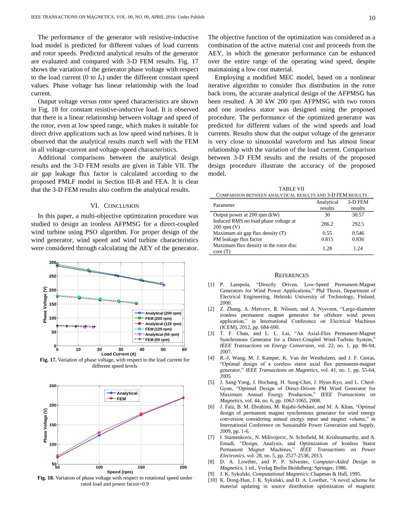
The performance of the generator with resistive-inductive
load model is predicted for different values of load currents
and rotor speeds. Predicted analytical results of the generator
are evaluated and compared with 3-D FEM results. Fig. 17
shows the variation of the generator phase voltage with respect
to the load current (0 to In) under the different constant speed
values. Phase voltage has linear relationship with the load
current.
Output voltage versus rotor speed characteristics are shown
in Fig. 18 for constant resistive-inductive load. It is observed
that there is a linear relationship between voltage and speed of
the rotor, even at low speed range, which makes it suitable for
direct drive applications such as low speed wind turbines. It is
observed that the analytical results match well with the FEM
in all voltage-current and voltage-speed characteristics.
Additional comparisons between the analytical design
results and the 3-D FEM results are given in Table VII. The
air gap leakage flux factor is calculated according to the
proposed PMLF model in Section III-B and FEA. It is clear
that the 3-D FEM results also confirm the analytical results.
VI. CONCLUSION
In this paper, a multi-objective optimization procedure was
studied to design an ironless AFPMSG for a direct-coupled
wind turbine using PSO algorithm. For proper design of the
wind generator, wind speed and wind turbine characteristics
were considered through calculating the AEY of the generator.
The objective function of the optimization was considered as a
combination of the active material cost and proceeds from the
AEY, in which the generator performance can be enhanced
over the entire range of the operating wind speed, despite
maintaining a low cost material.
Employing a modified MEC model, based on a nonlinear
iterative algorithm to consider flux distribution in the rotor
back irons, the accurate analytical design of the AFPMSG has
been resulted. A 30 kW 200 rpm AFPMSG with two rotors
and one ironless stator was designed using the proposed
procedure. The performance of the optimized generator was
predicted for different values of the wind speeds and load
currents. Results show that the output voltage of the generator
is very close to sinusoidal waveform and has almost linear
relationship with the variation of the load current. Comparison
between 3-D FEM results and the results of the proposed
design procedure illustrate the accuracy of the proposed
model.
REFERENCES
[1] P. Lampola, “Directly Driven, Low-Speed Permanent-Magnet
Generators for Wind Power Applications,” Phd Thesis, Department of Electrical Engineering, Helsinki University of Technology, Finland,
2000. [2] Z. Zhang, A. Matveev, R. Nilssen, and A. Nysveen, “Large-diameter
ironless permanent magnet generator for offshore wind power
application,” in International Conference on Electrical Machines (ICEM), 2012, pp. 684-690.
[3] T. F. Chan, and L. L. Lai, “An Axial-Flux Permanent-Magnet
Synchronous Generator for a Direct-Coupled Wind-Turbine System,” IEEE Transactions on Energy Conversion, vol. 22, no. 1, pp. 86-94,
2007.
[4] R.-J. Wang, M. J. Kamper, K. Van der Westhuizen, and J. F. Gieras, “Optimal design of a coreless stator axial flux permanent-magnet
generator,” IEEE Transactions on Magnetics, vol. 41, no. 1, pp. 55-64,
2005. [5] J. Sang-Yong, J. Hochang, H. Sung-Chin, J. Hyun-Kyo, and L. Cheol-
Gyun, “Optimal Design of Direct-Driven PM Wind Generator for
Maximum Annual Energy Production,” IEEE Transactions on Magnetics, vol. 44, no. 6, pp. 1062-1065, 2008.
[6] J. Faiz, B. M. Ebrahimi, M. Rajabi-Sebdani, and M. A. Khan, “Optimal
design of permanent magnet synchronous generator for wind energy conversion considering annual energy input and magnet volume,” in
International Conference on Sustainable Power Generation and Supply,
2009, pp. 1-6. [7] I. Stamenkovic, N. Milivojevic, N. Schofield, M. Krishnamurthy, and A.
Emadi, “Design, Analysis, and Optimization of Ironless Stator
Permanent Magnet Machines,” IEEE Transactions on Power Electronics, vol. 28, no. 5, pp. 2527-2538, 2013.
[8] D. A. Lowther, and P. P. Silvester, Computer-Aided Design in
Magnetics, 1 ed., Verlag Berlin Heidelberg: Springer, 1986. [9] J. K. Sykulski, Computational Magnetics: Chapman & Hall, 1995.
[10] K. Dong-Hun, J. K. Sykulski, and D. A. Lowther, “A novel scheme for
material updating in source distribution optimization of magnetic
50 100 150 20050
100
150
200
250
Speed (rpm)
Ph
as
e V
olt
ag
e (
V)
Analytical
FEM
Fig. 18. Variation of phase voltage with respect to rotational speed under
rated load and power factor=0.9
0 10 20 30 40 50 600
50
100
150
200
250
300
Load Current (A)
Ph
as
e V
olt
ag
e (
V)
Analytical (200 rpm)
FEM (200 rpm)
Analytical (125 rpm)
FEM (125 rpm)
Analytical (50 rpm)
FEM (50 rpm)
Fig. 17. Variation of phase voltage, with respect to the load current for
different speed levels
TABLE VII COMPARISON BETWEEN ANALYTICAL RESULTS AND 3-D FEM RESULTS
Parameter Analytical
results
3-D FEM
results
Output power at 200 rpm (kW) 30 30.57
Induced RMS no load phase voltage at 200 rpm (V)
286.2 292.5
Maximum air gap flux density (T) 0.55 0.546
PM leakage flux factor 0.815 0.836 Maximum flux density in the rotor disc
core (T) 1.28 1.24

IEEE TRANSACTIONS ON MAGNETICS, VOL. 00, NO. 00, APRIL 2016- Under Publish
11
devices using sensitivity analysis,” IEEE Transactions on Magnetics,
vol. 41, no. 5, pp. 1752-1755, 2005. [11] P. Di Barba, A. Savini, and S. Wiak, Field Models in Electricity and
Magnetism, Netherlands: Springer, 2008.
[12] P. Di Barba, Multiobjective Shape Design in Electricity and Magnetism, 1 ed., Netherlands: Springer, 2010.
[13] G. I. Hawe, and J. K. Sykulski, “A Scalarizing One-Stage Algorithm for
Efficient Multi-Objective Optimization,” IEEE Transactions on Magnetics, vol. 44, no. 6, pp. 1094-1097, 2008.
[14] D. A. Lowther, “The Development of Industrially-Relevant
Computational Electromagnetics Based Design Tools,” IEEE Transactions on Magnetics, vol. 49, no. 5, pp. 2375-2380, 2013.
[15] N. Rostami, M. R. Feyzi, J. Pyrhonen, A. Parviainen, and V. Behjat,
“Genetic Algorithm Approach for Improved Design of a Variable Speed Axial-Flux Permanent-Magnet Synchronous Generator,” IEEE
Transactions on Magnetics, vol. 48, no. 12, pp. 4860-4865, 2012.
[16] A. Mahmoudi, S. Kahourzade, N. A. Rahim, and W. P. Hew, “Design, Analysis, and Prototyping of an Axial-Flux Permanent Magnet Motor
Based on Genetic Algorithm and Finite-Element Analysis,” IEEE
Transactions on Magnetics, vol. 49, no. 4, pp. 1479-1492, 2013. [17] B. Sheikh-Ghalavand, S. Vaez-Zadeh, and A. H. Isfahani, “An Improved
Magnetic Equivalent Circuit Model for Iron-Core Linear Permanent-
Magnet Synchronous Motors,” IEEE Transactions on Magnetics, vol. 46, no. 1, pp. 112-120, 2010.
[18] Q. Ronghai, and T. A. Lipo, “Analysis and modeling of air-gap and
zigzag leakage fluxes in a surface-mounted permanent-magnet Machine,” IEEE Transactions on Industry Applications, vol. 40, no. 1,
pp. 121-127, 2004. [19] M. Sadeghierad, A. Darabi, H. Lesani, and H. Monsef, “Rotor Yoke
Thickness of Coreless High-Speed Axial-Flux Permanent Magnet
Generator,” IEEE Transactions on Magnetics, vol. 45, no. 4, pp. 2032-2037, 2009.
[20] S. Mohammadi, and M. Mirsalim, “Analytical Design Framework for
Torque and Back-EMF Optimization, and Inductance Calculation in Double-Rotor Radial-Flux Air-Cored Permanent-Magnet Synchronous
Machines,” IEEE Transactions on Magnetics, vol. 50, no. 1, pp. 1-16,
2014. [21] X. Yuanye, K. H. Ahmed, and B. W. Williams, “Wind Turbine Power
Coefficient Analysis of a New Maximum Power Point Tracking
Technique,” IEEE Transactions on Industrial Electronics, vol. 60, no. 3, pp. 1122-1132, 2013.
[22] "Wind energy resources 30 kW wind turbine," 4 March, 2016 [Online].
Available: http://wind-energy-resources.com/wer_30kw_wind_turbine-.html.
[23] "Hummer 30kW Wind Turbine," 4 March, 2016 [Online]. Available:
http://www.chinahummer.cn/index.php/index/content/28. [24] "Huaya 30 kW pitch controlled wind turbine ", 4 March, 2016 [Online].
Available: http://www.huayaturbine.com/te_product_a_c765/2012-06-
01/2029.chtml. [25] "Aeolos 30kw wind turbine specification," 4 March, 2016 [Online].
Available: http://www.windturbinestar.com/30kwh-aeolos-wind-turbine-
.html. [26] J. F. Gieras, R. J. Wang, and M. J. Kamper, Axial Flux Permanent
Magnet Brushless Machines, 2nd ed., New York: Springer, 2008, ch. 2,
pp. 45-60, ch. 3, pp. 92-119. [27] M. J. Kamper, W. Rong-Jie, and F. G. Rossouw, “Analysis and
Performance of Axial Flux Permanent-Magnet Machine With Air-Cored
Nonoverlapping Concentrated Stator Windings,” IEEE Transactions on Industry Applications, vol. 44, no. 5, pp. 1495-1504, 2008.
[28] A. Parviainen, M. Niemela, J. Pyrhonen, and J. Mantere, “Performance
comparison between low-speed axial-flux and radial-flux permanent-magnet machines including mechanical constraints,” in IEEE
International Conference on Electric Machines and Drives 2005, pp.
1695-1702. [29] W. Rong-Jie, and M. J. Kamper, “Calculation of eddy current loss in
axial field permanent-magnet machine with coreless stator,” IEEE
Transactions on Energy Conversion, vol. 19, no. 3, pp. 532-538, 2004. [30] J. Azzouzi, G. Barakat, and B. Dakyo, “Quasi-3-D analytical modeling
of the magnetic field of an axial flux permanent-magnet synchronous
machine,” IEEE Transactions on Energy Conversion, vol. 20, no. 4, pp. 746-752, 2005.
[31] Y. Kano, T. Kosaka, and N. Matsui, “Simple Nonlinear Magnetic Analysis for Permanent-Magnet Motors,” IEEE Transactions on
Industry Applications, vol. 41, no. 5, pp. 1205-1214, 2005.
[32] S. Helwig, “Particle Swarms for Constrained Optimization,” Phd Thesis, University of Erlangen-Nurnberg, 2010.
[33] F. Giulii Capponi, G. De Donato, and F. Caricchi, “Recent Advances in
Axial-Flux Permanent-Magnet Machine Technology,” IEEE Transactions on Industry Applications, vol. 48, no. 6, pp. 2190-2205,
2012.
[34] Z. Zhaoqiang, A. Matveev, R. Nilssen, and A. Nysveen, “Ironless Permanent-Magnet Generators for Offshore Wind Turbines,” IEEE
Transactions on Industry Applications, vol. 50, no. 3, pp. 1835-1846,
2014. [35] "Average electricity prices around the world," 2011 [Online]. Available:
https://www.ovoenergy.com/guides/energy-guides/average-electricity-
prices-kwh.html.