design of wideband printed antenna array in corner...
TRANSCRIPT

98 Telfor Journal, Vol. 8, No. 2, 2016.
Abstract — The paper presents a wideband printed antenna array with a cosecant square-shaped beam pattern. The array is with four symmetrical pentagonal dipoles as radiating elements operating at the second resonance. The apex of the corner reflector is at a distance λ0/2 from antenna array. Orchard Elliott’s methods and genetic algorithm are used for synthesizing the proposed antenna. A symmetrical tapered feed network of impedance transformers enables a required distribution. Simulated and measured results show that proposed antenna model has a 15 dBi gain and side lobe suppression around 20 dB in E-plane at the frequency of 10 GHz.
Keywords — Printed antenna array, Cosecant square radiation pattern, Symmetric printed technique, Feeding network.
I. INTRODUCTION NTENNA arrays with a cosecant square-shaped beam pattern are the most often employed by airborne
search radars observing ground targets, as well as by ground-based radars observing aircraft targets. Coverage of a simple fan beam is usually inadequate for targets at high altitudes close to the radar [1]. A simple fan-beam antenna radiates very little of its energy in this direction. However, there are a few techniques for modifying the antenna pattern to radiate more energy at higher angles. One technique for accomplishing this is to employ a fan beam with a shape proportional to the square of the cosecant of the elevation angle [1]. Moreover, a cosecant-squared antenna produces a constant echo-signal power for a target flying at a constant altitude, if certain assumptions are satisfied.
Paper received December 2, 2015; revised September 21, 2016;
accepted November 4, 2016. Date of publication November 20, 2016. The associate editor coordinating the review of this manuscript and approving it for publication was Prof. Branko Kolundžija.
This paper is a revised and expanded version of the paper presented
at the 23rd Telecommunications Forum TELFOR 2014 [11].
This work was supported by the Ministry of Education, Science and Technological Development of Republic Serbia within the projects No. TR 32052.
Marija Milijić is with the University of Niš, Faculty of Electronic Engineering, Aleksandra Medvedeva 14, 18000 Niš, Serbia, E-mail: [email protected]
Aleksandar Nešić is with "IMTEL-komunikacije" a.d., Bulevar Mihaila Pupina 165b, 11070 Novi Beograd, Serbia, E-mail: [email protected]
Bratislav Milovanović is with the University Singidunum, 32 Danijelova Street, Beograd, Serbia, E-mail: [email protected]
Ivana Radnović is with "IMTEL-komunikacije" a.d., Bulevar Mihaila Pupina 165b, 11070 Novi Beograd, Serbia, E-mail: [email protected].
The cosecant-squared antenna may be constructed by a distortion section of a parabola or by a true parabola with a properly designed set of multiple feed horns. The cosecant-squared pattern may also be generated with an array-type antenna. The pattern produced by approximation with a parabolic antenna may not be as accurate as it might be when produced by a well-designed array antenna.
There are many algorithms and methods for design of cosecant-squared antennas [2-4]. However, few papers deal with the methods of realization of these antennas as printed structures. The main problem of the printed antennas with a cosecant squared-shaped beam pattern is their bandwidth. The proposed antenna model is wideband thanks to its radiating elements of symmetrical pentagonal shape. In addition, other antenna parameters are within satisfactory limits, and the complete structure is simple and easy to fabricate.
Cosecant-squared antennas are widely used for radars in lower microwave frequency, especially in the L band. This paper will present the antenna array in the X band, around 10 GHz. In this band, the functional antenna model has been fabricated and measured to economize material and space. Of course, the presented concept can be used in every UHF and microwave frequency band, relevant for cosecant-squared antennas, using dimensions scaling.
II. SYMMETRICAL PENTAGONAL PRINTED DIPOLES Presented cosecant-squared antenna array is with
symmetrical printed dipoles (Fig. 1) of pentagonal shape [5-7] (one half of them on one side and another half on the opposite side of the substrate).
Fig. 1 Pentagonal dipole.
The pentagonal dipole is fed by a symmetrical (balanced) printed line. It is with a 60° angle corner reflector whose apex is at a distance λ0/2 from its center. Differently from conventional dipoles that operate at the first resonance, this dipole operates at the second resonance [5-7]. The dipole’s impedance varies with frequency very slowly (Fig. 2). Fig. 3 presents the voltage standing wave ratio (VSWR) of a pentagonal dipole.
Design of Wideband Printed Antenna Array in Corner Reflector with Cosecant Square-Shaped Beam Pattern
Marija Milijić, Graduate Student Member, IEEE, Aleksandar Nešić, Life Member, IEEE, Bratislav Milovanović, Member, IEEE, and Ivana Radnović, Member, IEEE
A

Milijić et al.: Design of Wideband Printed Antenna Array with Cosecant Square-Shaped Beam Pattern 99
Fig. 2 Real and imaginary part of pentagonal dipole‘s
impedance.
Fig. 3 VSWR of a pentagonal dipole.
VSWR is below 2 in the range from 9.3 GHz to 11.6 GHz, which amounts to 23% of the central frequency. Modification of pentagonal dipole’s dimensions enables us to change impedance at the second resonance in a relatively wide range of frequencies (Fig. 2). In our case, we have adjusted the dimensions of pentagonal dipoles in order to obtain a dipole impedance of Zd = 100 Ω at the center frequency (fc = 10 GHz), taking into consideration the influence of the reflector.
III. ANTENNA ARRAY WITH COSECANT SQUARED RADIATION PATTERN
Cosecant function of angle φ is defined as:
φφ
sin1csc = . (1)
In the cosecant-squared antenna, the gain as a function of elevation angle is given by [1]:
02
2
0 csccsc)()(
φφφφ GG = for 0φ < φ < mφ , (2)
where )(φG is the gain at elevation angleφ , and 0φ and
mφ are angular limits between which the beam follows a cosecant-squared shape. From φ =0 to φ = 0φ , the antenna pattern is similar to a normal antenna pattern, but from φ = 0φ to φ = mφ , the antenna gain varies as csc2 φ .
Fig. 4 Simulated cosecant square radiation pattern for a
four-element linear array [3].
Fig. 5 Antenna array with cosecant squared radiation.
Pattern.
Ideally, the upper limit 0φ should be 90°, but it is always much less than this with a single antenna due to practical difficulties. The simulated pattern and the desired coverage for a four-element linear array with a distance between the dipoles d = 0.8 λ0 is shown in Fig.4 [3].
The presented antenna array consists of four parts (Fig. 5): (1) the axial array of four radiating elements, (2) feeding network, (3) balun and (4) a 60° corner reflector. Parts (1), (2), and (3) are printed on the same dielectric substrate of 0.508 mm thickness, dielectric constant εr = 2.17, 41 MS/m electrical conductivity, and insignificantly small values of loss tangent and conductor thickness. The dipoles in the array are axially placed decreasing their mutual impedance. Symmetrical (balanced) printed line is used as a feeding structure, because dipoles are electrically symmetrical elements. Distance between the dipoles is d = 0.8λ0 = 24 mm (at the center frequency fc = 10 GHz).
TABLE I: THE DISTRIBUTION COEFFICIENTS FOR ANTENNA ARRAY WITH COSECANT SQUARED RADIATION PATTERN.
Dipoles number 1 2 3 4 Normalized amplitude ui 0.4038 0.567 1 0.725 Phase shifts φi [°] 0 14 0 −36
100 Telfor Journal, Vol. 8, No. 2, 2016.
IV. FEEDING NETWORK The feeding network begins with a balun for transition
from conventional printed to symmetrical printed structure. After that, there is a feeding network that enables necessary amplitude and phase distributions obtained by Orchard Elliott’s methods and genetic algorithm. The normalized amplitude, ui and phase shifts φi, i=1,2,3,4 for four radiating elements are shown in Table I [2,3].
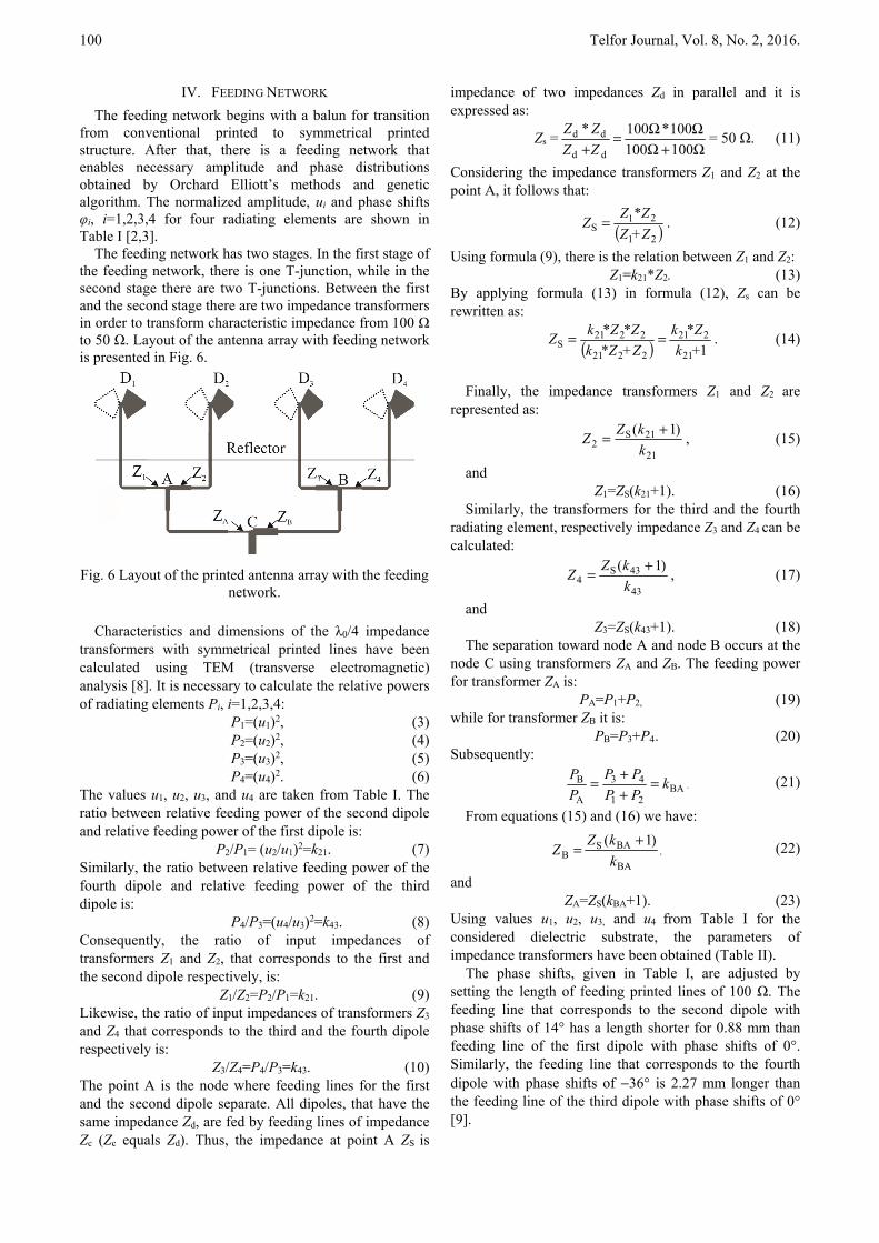
The feeding network has two stages. In the first stage of the feeding network, there is one T-junction, while in the second stage there are two T-junctions. Between the first and the second stage there are two impedance transformers in order to transform characteristic impedance from 100 Ω to 50 Ω. Layout of the antenna array with feeding network is presented in Fig. 6.
Fig. 6 Layout of the printed antenna array with the feeding
network.
Characteristics and dimensions of the λ0/4 impedance transformers with symmetrical printed lines have been calculated using TEM (transverse electromagnetic) analysis [8]. It is necessary to calculate the relative powers of radiating elements Pi, i=1,2,3,4:
P1=(u1)2, (3) P2=(u2)2, (4) P3=(u3)2, (5) P4=(u4)2. (6)
The values u1, u2, u3, and u4 are taken from Table I. The ratio between relative feeding power of the second dipole and relative feeding power of the first dipole is:
P2/P1= (u2/u1)2=k21. (7) Similarly, the ratio between relative feeding power of the fourth dipole and relative feeding power of the third dipole is:
P4/P3=(u4/u3)2=k43. (8) Consequently, the ratio of input impedances of transformers Z1 and Z2, that corresponds to the first and the second dipole respectively, is:
Z1/Z2=P2/P1=k21. (9) Likewise, the ratio of input impedances of transformers Z3 and Z4 that corresponds to the third and the fourth dipole respectively is:
Z3/Z4=P4/P3=k43. (10) The point A is the node where feeding lines for the first and the second dipole separate. All dipoles, that have the same impedance Zd, are fed by feeding lines of impedance Zc (Zc equals Zd). Thus, the impedance at point A ZS is
impedance of two impedances Zd in parallel and it is expressed as:
Zs =Ω+ΩΩΩ=
+ 100100100*100*
dd
ddZZZZ = 50 Ω. (11)
Considering the impedance transformers Z1 and Z2 at the point A, it follows that:
( )21
21S +ZZ
*ZZZ = . (12)
Using formula (9), there is the relation between Z1 and Z2: Z1=k21*Z2. (13)
By applying formula (13) in formula (12), Zs can be rewritten as:
( ) 121
221
2221
2221S +k
*Zk+Z*Zk*Z*ZkZ == . (14)
Finally, the impedance transformers Z1 and Z2 are
represented as:
21
21S2
)1(kkZZ += , (15)
and Z1=ZS(k21+1). (16)
Similarly, the transformers for the third and the fourth radiating element, respectively impedance Z3 and Z4 can be calculated:
43
43S4
)1(kkZZ += , (17)
and Z3=ZS(k43+1). (18)
The separation toward node A and node B occurs at the node C using transformers ZA and ZB. The feeding power for transformer ZA is:
PA=P1+P2, (19) while for transformer ZB it is:
PB=P3+P4 . (20) Subsequently:
BA21
43
A
B kPPPP
PP =
++= . (21)
From equations (15) and (16) we have:
BA
BASB
)1(kkZZ +
= , (22)
and
ZA=ZS(kBA+1). (23) Using values u1, u2, u3, and u4 from Table I for the considered dielectric substrate, the parameters of impedance transformers have been obtained (Table II).
The phase shifts, given in Table I, are adjusted by setting the length of feeding printed lines of 100 Ω. The feeding line that corresponds to the second dipole with phase shifts of 14° has a length shorter for 0.88 mm than feeding line of the first dipole with phase shifts of 0°. Similarly, the feeding line that corresponds to the fourth dipole with phase shifts of −36° is 2.27 mm longer than the feeding line of the third dipole with phase shifts of 0° [9].
Milijić et al.: Design of Wideband Printed Antenna Array with Cosecant Square-Shaped Beam Pattern 101
TABLE II: THE PARAMETERS OF IMPEDANCE TRANSFORMERS OF THE FEEDING NETWORK
Transformers of impedance Width [mm] Characteristic
impedance [Ω]Z1 0.57 121.89Z2 0.96 86.81Z3 0.955 87.34Z4 0.58 120.47ZA 0.43 144.03ZB 1.06 81.17
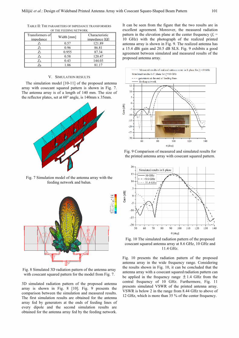
V. SIMULATION RESULTS The simulation model [10-11] of the proposed antenna
array with cosecant squared pattern is shown in Fig. 7. The antenna array is of a length of 140 mm. The size of the reflector plates, set at 60° angle, is 140mm x 35mm.
Fig. 7 Simulation model of the antenna array with the
feeding network and balun.
Fig. 8 Simulated 3D radiation pattern of the antenna array with cosecant squared pattern for the model from Fig. 7.
3D simulated radiation pattern of the proposed antenna array is shown in Fig. 8 [10]. Fig. 9 presents the comparison between the simulation and measured results. The first simulation results are obtained for the antenna array fed by generators at the ends of feeding lines of every dipole and the second simulation results are obtained for the antenna array fed by the feeding network.
It can be seen from the figure that the two results are in excellent agreement. Moreover, the measured radiation pattern in the elevation plane at the center frequency (fc = 10 GHz) with the photograph of the realized printed antenna array is shown in Fig. 9. The realized antenna has a 15.4 dBi gain and 20.5 dB SLS. Fig. 9 exhibits a good agreement between simulated and measured results of the proposed antenna array.
Fig. 9 Comparison of measured and simulated results for the printed antenna array with cosecant squared pattern.
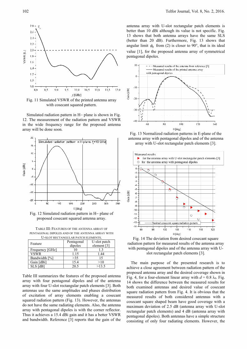
Fig. 10 The simulated radiation pattern of the proposed cosecant squared antenna array at 8.6 GHz, 10 GHz and
11.4 GHz. Fig. 10 presents the radiation pattern of the proposed antenna array in the wide frequency range. Considering the results shown in Fig. 10, it can be concluded that the antenna array with a cosecant squared radiation pattern can be applied in the frequency range ± 1.4 GHz from the central frequency of 10 GHz. Furthermore, Fig. 11 presents simulated VSWR of the printed antenna array. VSWR is below 2 in the range from 8.44 GHz to above of 12 GHz, which is more than 35 % of the center frequency.
102 Telfor Journal, Vol. 8, No. 2, 2016.
Fig. 11 Simulated VSWR of the printed antenna array
with cosecant squared pattern.
Simulated radiation pattern in H− plane is shown in Fig. 12. The measurement of the radiation pattern and VSWR in the wide frequency range for the proposed antenna array will be done soon.
Fig. 12 Simulated radiation pattern in H− plane of
proposed cosecant squared antenna array.
TABLE III: FEATURES OF THE ANTENNA ARRAY OF
PENTAGONAL DIPOLES AND OF THE ANTENNA ARRAY WITH U-SLOT RECTANGULAR PATCH ELEMENTS.
Feature Pentagonal dipoles
U-slot patch element [3]
Frequency [GHz] 10 1.3VSWR 1.15 1.44Bandwidth [%] >35 15Gain [dBi] 15.4 >10SLS [dB] 20.5 >13.5
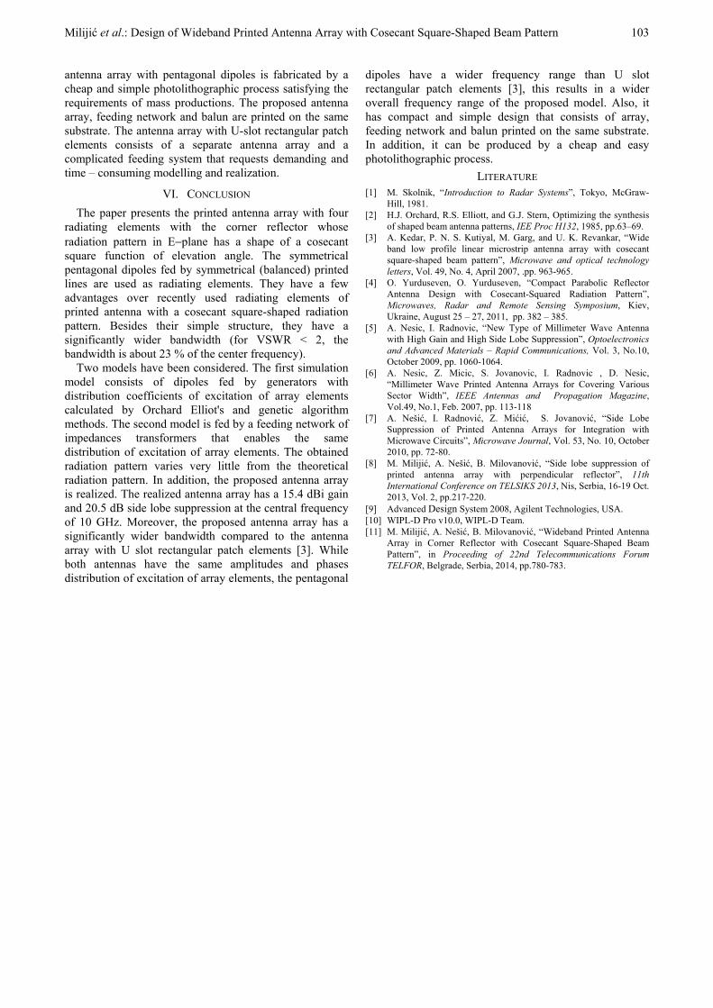
Table III summarizes the features of the proposed antenna array with four pentagonal dipoles and of the antenna array with four U-slot rectangular patch elements [3]. Both antennas use the same amplitudes and phases distribution of excitation of array elements enabling a cosecant squared radiation pattern (Fig. 13). However, the antennas do not have the same radiating elements. Also, the antenna array with pentagonal dipoles is with the corner reflector. Thus it achieves a 15.4 dBi gain and it has a better VSWR and bandwidth. Reference [3] reports that the gain of the
antenna array with U-slot rectangular patch elements is better than 10 dBi although its value is not specific. Fig. 13 shows that both antenna arrays have the same SLS (better than 20 dB). Furthermore, Fig. 13 shows that angular limit 0φ from (2) is closer to 90°, that is its ideal value [1], for the proposed antenna array of symmetrical pentagonal dipoles.
Fig. 13 Normalized radiation patterns in E-plane of the
antenna array with pentagonal dipoles and of the antenna array with U-slot rectangular patch elements [3].
Fig. 14 The deviation from desired cosecant square
radiation pattern for measured results of the antenna array with pentagonal dipoles and of the antenna array with U-
slot rectangular patch elements [3].
The main purpose of the presented research is to achieve a close agreement between radiation pattern of the proposed antenna array and the desired coverage shown in Fig. 4, for a four-element linear array with d = 0.8 λ0. Fig. 14 shows the difference between the measured results for both examined antennas and desired value of cosecant square radiation pattern from Fig. 4. It is obvious that the measured results of both considered antennas with a cosecant square shaped beam have good coverage with a maximum deviation of 2.5 dB (antenna array with U-slot rectangular patch elements) and 4 dB (antenna array with pentagonal dipoles). Both antennas have a simple structure consisting of only four radiating elements. However, the
Milijić et al.: Design of Wideband Printed Antenna Array with Cosecant Square-Shaped Beam Pattern 103
antenna array with pentagonal dipoles is fabricated by a cheap and simple photolithographic process satisfying the requirements of mass productions. The proposed antenna array, feeding network and balun are printed on the same substrate. The antenna array with U-slot rectangular patch elements consists of a separate antenna array and a complicated feeding system that requests demanding and time – consuming modelling and realization.
VI. CONCLUSION The paper presents the printed antenna array with four
radiating elements with the corner reflector whose radiation pattern in E−plane has a shape of a cosecant square function of elevation angle. The symmetrical pentagonal dipoles fed by symmetrical (balanced) printed lines are used as radiating elements. They have a few advantages over recently used radiating elements of printed antenna with a cosecant square-shaped radiation pattern. Besides their simple structure, they have a significantly wider bandwidth (for VSWR < 2, the bandwidth is about 23 % of the center frequency).
Two models have been considered. The first simulation model consists of dipoles fed by generators with distribution coefficients of excitation of array elements calculated by Orchard Elliot's and genetic algorithm methods. The second model is fed by a feeding network of impedances transformers that enables the same distribution of excitation of array elements. The obtained radiation pattern varies very little from the theoretical radiation pattern. In addition, the proposed antenna array is realized. The realized antenna array has a 15.4 dBi gain and 20.5 dB side lobe suppression at the central frequency of 10 GHz. Moreover, the proposed antenna array has a significantly wider bandwidth compared to the antenna array with U slot rectangular patch elements [3]. While both antennas have the same amplitudes and phases distribution of excitation of array elements, the pentagonal
dipoles have a wider frequency range than U slot rectangular patch elements [3], this results in a wider overall frequency range of the proposed model. Also, it has compact and simple design that consists of array, feeding network and balun printed on the same substrate. In addition, it can be produced by a cheap and easy photolithographic process.
LITERATURE [1] M. Skolnik, “Introduction to Radar Systems”, Tokyo, McGraw-
Hill, 1981. [2] H.J. Orchard, R.S. Elliott, and G.J. Stern, Optimizing the synthesis
of shaped beam antenna patterns, IEE Proc H132, 1985, pp.63–69. [3] A. Kedar, P. N. S. Kutiyal, M. Garg, and U. K. Revankar, “Wide
band low profile linear microstrip antenna array with cosecant square-shaped beam pattern”, Microwave and optical technology letters, Vol. 49, No. 4, April 2007, .pp. 963-965.
[4] O. Yurduseven, O. Yurduseven, “Compact Parabolic Reflector Antenna Design with Cosecant-Squared Radiation Pattern”, Microwaves, Radar and Remote Sensing Symposium, Kiev, Ukraine, August 25 – 27, 2011, pp. 382 – 385.
[5] A. Nesic, I. Radnovic, “New Type of Millimeter Wave Antenna with High Gain and High Side Lobe Suppression”, Optoelectronics and Advanced Materials – Rapid Communications, Vol. 3, No.10, October 2009, pp. 1060-1064.
[6] A. Nesic, Z. Micic, S. Jovanovic, I. Radnovic , D. Nesic, “Millimeter Wave Printed Antenna Arrays for Covering Various Sector Width”, IEEE Antennas and Propagation Magazine, Vol.49, No.1, Feb. 2007, pp. 113-118
[7] A. Nešić, I. Radnović, Z. Mićić, S. Jovanović, “Side Lobe Suppression of Printed Antenna Arrays for Integration with Microwave Circuits”, Microwave Journal, Vol. 53, No. 10, October 2010, pp. 72-80.
[8] M. Milijić, A. Nešić, B. Milovanović, “Side lobe suppression of printed antenna array with perpendicular reflector”, 11th International Conference on TELSIKS 2013, Nis, Serbia, 16-19 Oct. 2013, Vol. 2, pp.217-220.
[9] Advanced Design System 2008, Agilent Technologies, USA. [10] WIPL-D Pro v10.0, WIPL-D Team. [11] M. Milijić, A. Nešić, B. Milovanović, “Wideband Printed Antenna
Array in Corner Reflector with Cosecant Square-Shaped Beam Pattern”, in Proceeding of 22nd Telecommunications Forum TELFOR, Belgrade, Serbia, 2014, pp.780-783.