design of water retaining structures to ec
DESCRIPTION
By Doug KayTRANSCRIPT

1
DESIGN OF WATER RETAINING STRUCTURES TO EUROCODES
ByDoug Kay
Associate Director
10th Jan 2012
2
Design of Water Retaining Structures
Introduction
Eurocodes
Actions on structures and partial factors
Durability
Ultimate Limit State Design
Serviceability Limit State
Crack control
Flexural Cracking
Thermal Cracking
Geotechnical Design
Detailing Rules

3
What is a Water Retaining Structure?
4
What is a Water Retaining Structure?

5
What is a Water Retaining Structure?
6
What is a Water Retaining Structure?

7
What is a Water Retaining Structure?
8
What is a Water Retaining Structure?

9
What is a Water Retaining Structure?
10
What is a Water Retaining Structure?
The code of practice uses the term “liquid”
The code of practice defines “tank” as a “containment structure used to store liquids”
The design rules for tanks apply only to tanks storing liquids at normal atmospheric pressure
What is a Liquid Retaining Structure?

11
EN 1992-3 Liquid retaining and containment structures
Additional rules for structures constructed from concrete for containment of liquid and granular solids
This is to be read in conjunction with EN1992-1-1.
This does NOT cover
Storage of material at very low or very high temperatures
Storage of hazardous materials where leakage could constitute a major health or safety risk
The selection and design of liners or coatings
Pressurised vessels
Floating structures
Large Dams
Gas tightness
12
Eurocodes
Eurocode 0, Basis of Design
Eurocode 1, Actions on structures
EN 1991-1-5, Part 1-5: General Actions – Thermal actions
EN 1991-4, Part 4: Silos and Tanks
Eurocode 2, Design of Concrete Structures
EN 1992-1-1, Part 1-1: General rules and rules for buildings
EN 1992-3, Part 3: Liquid Retaining and Containment Structures
Eurocode 7, Geotechnical Design of Concrete Structures
EN 1997-1,Part 1: General rules
Eurocode 3, Design of Steel Structures
EN 1993-4-2, Part 4.2: Steel Tanks

13
Eurocode 2/BS8110 Compared
Code deals with phenomenon, rather than element types
Design is based on characteristic cylinder strength
Does not contain derived formulae (e.g. only the details of the stress block is given, not the flexural design formulae)
Units of stress in MPa
One thousandth is represented by %o
Plain or mild steel not covered
Notional horizontal loads considered in addition to lateral loads
Higher strength, up to C90/105 covered.
14
Action on Structures
Section 2 - Representation and classification of actions Liquids shall be represented by a hydrostatic distributed load Variable Fixed action
Section 3 - Design Situation Loads shall be considered both when tank is in operation and full If levels are different then the “Full” shall be considered an
accidental action Section 7 - Loading on tanks due to liquid The characteristic value of pressure p should be determined as:p(z) = z … (7.1)where:z is the depth below the liquid surface; is the unit weight of the liquid.
From EN1991-4

15
EN 1990: Classification of Actions
Variation in time: Permanent (ie Dead Load) Variable (ie Live Load) Accidental (ie Impact Load)
Origin: Direct (ie Dead or Live Load) Indirect (ie Shrinkage, settlement)
Spatial Variation: Fixed (ie Dead Load) Free (ie Live Load, Vehicle)
Nature and/or structural response: Static (ie Dead and Live Load)Dynamic (ie Vibration from Pumps)
16
Action on Structures
Annex B - Actions, partial factors and combinations of actions on tanks Liquid induced loads F = 1,20 for operational F = 1,0 for testing Internal pressure loads See EN 1990 Thermally induced loads See EN 1990 Self weight loads See EN 1990 Insulation loads See EN 1990 Distributed imposed load See EN 1990 Concentrated imposed load See EN 1990 Snow See EN 1990 Wind See EN 1990 Suction due to inadequate venting See EN 1990 Seismic loadings See EN 1990 Loads resulting from connections See EN 1990 Loads resulting from uneven settlementSee EN 1990 Accidental actions F = 1,0
From EN1991-4

17
Action on Structures
Annex B - Actions, partial factors and combinations of actions on tanks
Combination of actions
The general requirements of EN 1990, Section 6 shall be followed.
Imposed loads and snow loads need not be considered to act simultaneously.
Seismic actions need not be considered to act during test conditions.
Accidental actions need not be considered to act during test conditions, but that the combination rules for accidental actions given in EN 1990 are applied.
From EN1991-4
18
EN 1990: Basis of Design
Actions (F)
Permanent Actions (G)
Variable Actions (Q)
Accidental Actions (A)
Seismic Action (Ae)
Values of Actions
Representative Values of Actions– Characteristic Value (Qk)
– Combinations Value of a Variable Action (ψ0Qk)
– Frequent Value of a Variable Action (ψ1Qk)
– Quasi-permanent Value of a Variable Action (ψ2Qk)
(ψ) = Reduction Coefficients for Variable Actions Qk

19
Combinations for Ultimate Limit Statefor persistent or transient design
As is not defined for water assume = 1,0
Use 6.10
20
Combinations for Ultimate Limit Statefor accidental design situations
Note: EN1991-4 has given f=1,0 thus Ad=1,0xAccidental action
is not defined for water assume = 1,0

21
Combinations for Serviceability Limit Statefor persistent or transient design
As is not defined for water assume = 1,0
Frequent Actions
As is not defined for water assume = 1,0
Quasi-permanent Actions
22
Example
Persistent/transient & Quasi-permanentQwater = 10kN/m3 x 5m per m
= 50kN/m2 per mAccidentalQwater = 10kN/m3 x 6m per m
= 60kN/m2 per m
ULS – Persistent/transientTotal Action = 1,2x50=60kN/m2 per m
ULS - AccidentalTotal Action = 1,0x60=60kN/m2 per m
SLS - Quasi-permanentTotal Action = 1,0x50=50kN/m2 per m

23
Example
ULS – Persistent/transient
BM = 60x52/6 = 250kNm per m
SF = 60x5/2 = 150kN per m
ULS - Accidental
BM = 60x62/6 = 360kNm per m
SF = 60x6/2 = 180kN per m
SLS - Quasi-permanent
BM = 50x52/6 = 208kNm per m
24
EN 1992-3 Liquid retaining and containment structures
Additional rules for structures constructed from concrete for containment of liquid and granular solids
This is to be read in conjunction with EN1992-1-1.
This does NOT cover
Storage of material at very low or very high temperatures
Storage of hazardous materials where leakage could constitute a mjor health or safety risk
The selection and design of liners or coatings
Pressurised vessels
Floating structures
Large Dams
Gas tightness

25
Durability and cover to reinforcement
Nominal Cover
cnom=cmin+cdev
where
cmin should be set to satisfy the following:– Safe transmission of bond forces (ie > bar size)
– Durability
cdev is 10mm unless fabrication is QA then use 5mm
26
Durability and cover to reinforcement

27
Durability and cover to reinforcement
28
Concrete Specification
Minimum cement content to be 325kg/m3
100% CEM I and max w/c ratio 0.55 – Not recommended(Max cement not to exceed 450kg/m3)
CEM II/V-B or CII/V-B (with <35% pfa) and max w/c ratio 0.50 (Max cement not to exceed 450kg/m3)
CEM III/A or CIII/A (with <50% ggbs) and max w/c ratio 0.50 (Max cement not to exceed 400kg/m3)
29
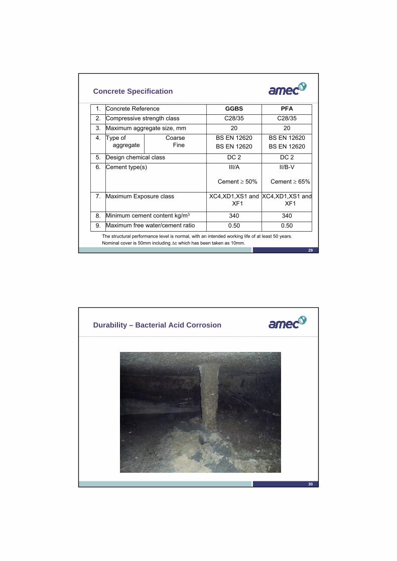
Concrete Specification
1. Concrete Reference GGBS PFA
2. Compressive strength class C28/35 C28/35
3. Maximum aggregate size, mm 20 20
4. Type of aggregate
CoarseFine
BS EN 12620
BS EN 12620
BS EN 12620
BS EN 12620
5. Design chemical class DC 2 DC 2
6. Cement type(s) III/A
Cement 50%
II/B-V
Cement 65%
7. Maximum Exposure class XC4,XD1,XS1 and XF1
XC4,XD1,XS1 and XF1
8. Minimum cement content kg/m3 340 340
9. Maximum free water/cement ratio 0.50 0.50
The structural performance level is normal, with an intended working life of at least 50 years.
Nominal cover is 50mm including c which has been taken as 10mm.
30
Durability – Bacterial Acid Corrosion

31
Durability – Low pH
32
Durability – Chemical attack (Aggressive CO2)

33
Durability - Abrasion
34
Ultimate Limit State Design
ckfbd
MK
2
21,018,06,0' 2 K
dKd
z 95,053,3112
It is often recommended in the UK that K’ is limited to 0.168 to ensure ductile failure
If K>K’ then not recommended thus amend section properties
zf
MA
yds
yk
tctms f
dbfA
26,0min,
Bending Moment

35
Ultimate Limit State Design
dbfkV wcklc
cRd
3
1
, 10018,0
02,0db
A
w
sll0,2
2001
dk 2
12
3
min 0035,0 ckfkv
dbvV wcRd min,
Shear Force
36
Example – Persistent/Transient
fck=30N/mm2 (Cylinder strength)
Cover, c = 40mm
Assume B20 bars
d = 450-40-20/2=400mm
K = 250x106/(1000x4002x30) = 0,052
K’ = 0,168 > K – No compression reinforcement require
z = 400/2x(1+(1-3,53x0,052))=380,7mm
0,95x400 = 380mm > z – Use 0,95d
As = 250x106/(0,87x500x380) = 1512mm2
Consider B20 at 200 (As=1570mm2)

37
Example – Accidental
fck=30N/mm2 (Cylinder strength)
Cover, c = 40mm
Assume B20 bars
d = 450-40-20/2=400mm
K = 360x106/(1000x4002x30) = 0,075
K’ = 0,168 > K – No compression reinforcement require
z = 400/2x(1+(1-3,53x0,075))=371,5mm
0,95x400 = 380mm > z – Use z
As = 360x106/(1,0x500x371,5) = 1938mm2
Consider B20 at 150 (As=2093mm2)
38
Example
Persistent/Transient l =2093/(1000x400)=0,00523 < 0,02 k =1+(200/400)=1,7071 < 2,0 VRd,c = [0,18/1,5x 1,7071 x(100x 0,00523x30)0.33]x1000x400=203,3kN VEd = 150kN < VRd,c
B20 at 150 (As=2093mm2) Okay Accidental l =2093/(1000x400)=0,00523 < 0,02 k =1+(200/400)=1,7071 < 2,0 VRd,c = [0,18/1,2x 1,7071 x(100x 0,00523x30)0.33]x1000x400=254,1kN VEd = 180kN < VRd,c
B20 at 150 (As=2093mm2) Okay
Shear Force

39
Serviceability Limit State (SLS)
Stress limitation
Crack Control
Deflection Control
40
SLS – Stress Limitation
This gives the limits on compressive stress in order to avoid longitudinal cracks, micro-cracks or high levels of creep
This limits the compressive stress to k1fckwhere
k1=0,6and
fck= characteristic compressive cylinder strength at 28 days
In addition if the stress under quasi-permanent loads is less than k2fcklinear creep can be assumedwhere
k2=0,45 This the requirement of EN1992-1-1 (Not EN1992-3) No stress checks have been undertaken for the past 50 years Provided the design has been carried properly to ULS – no issues expected

41
Crack Control
Flexural Cracking
Thermal Cracking incl Creep and Shrinkage Cracking
42
Crack Control
Classification of tightness
Tightness Class Requirement for leakage
0Some degree of leakage acceptable, or leakage of liquid irrelevant
1Leakage to be limited to a small amount. Some surface staining or damp patches acceptable
2Leakage to be minimal. Appearance not to be impaired by staining
3 No leakage permitted

43
Aesthetics
44
Crack Control
Appropriate limits to cracking
Tightness Class Provision
0 Adopt provisions in 7.3.1 of EN1992-1-1
1Crack expected to pass through whole section – use wk1
As Class 0 when full section is NOT cracked including min. compressive area and strain < 150x10-6
2Crack expected to pass through whole section to be avoided unless appropriate measures (eg liner or waterbar)
3Generally special measures will be required to watertightness (eg liner or prestress)

45
Crack Control
EN1992 Class 0 wk= 0,4 for X0,XC1 for
wk= 0,3 for XC2,XC3,XC4XD1,XD2XS1,XS2,XS3
Class 1For hD/h≤5, wk= 0,2For hD/h≥35, wk= 0,05linear interpolation between 0,2 & 0,05
Class 2 – No value given
Class 3 – No value given
BS8110 & BS8007 0.3mm BS8110 Part 2
0.2mm BS8007for severe or very severe exposure
0.1mm BS8007for critical aesthetic appearance
46
Example – Class 1
EN1992
hD = 5m depth of liquid
h = 0,45m wall thickness
hD/h= 11,11
Therefore interpolatewk=0,2–(11,11-5)x(0,2-0,05)/(35-5)
= 0,169mm
BS8007
Design crack width = 0.2mm

47
Flexural Cracking
48
Tension Cracking

49
Calculation of crack width
EN1992
(7.8)
(7.9)
(7.10)
(7.11) c=cover, =bar size kt = 0,6 short term
= 0,4 long term
Derived from Stress Block for bending
k1 = 0,8 high bond= 1,6 plain
k2 = 0,5 for bending= 1,0 for pure tension
k3 = 3,4 (National annex) k4 = 0,425 (National annex)
)(max, cmsmrk sw
s
s
s
effpeeffp
effctts
cmsm EE
fk
6,0
1 ,,
,
effc
s
effc
pseffp A
A
A
AA
,,
21
,
'
cm
se E
E
zA
M
s
ss .
3
xdz
5.22 20
eeed
x
effpr
kkkcks
,
4213max,
db
As
.
3.0
10
822
ckcm
fE
50
Example
EN1992
hD = 5m depth of liquid
h = 0,45m wall thickness
hD/h= 11,11
Therefore interpolatewk=0,2–(11,11-5)x(0,2-0,05)/(35-5)
= 0,169mm
BS8007
Design crack width = 0.2mm

51
Example – Crack Width
Determine stress in reinforcement
As =2093mm2
Ms =208kNm
e =200/{22x[(30+8)/10]0.3}=6,09
=2093/(1000x400)=0,00523
x ={6,09x0,00523+[6,092x0,005232+2x 6,09x0,00523]0.5}x400=89,1mm
z =400-89,1/3 = 370mm
s =208x106/(2093x370) =268,6N/mm2
zA
M
s
ss .
3
xdz
5.22 20
eeed
x
db
As
.
cm
se E
E
52
Example – Crack Width
Now calculate expression
Long term kt =0,4
For 28 days, fct,eff = fctm=2,9
Ac,eff= b x hc,ef where hc,ef = lesser of 2,5(h-d), (h-x)/3 or h/2 = 125mm, 120,3mm or 225mm
p,eff =2053/(1000x120,3) = 0,01706
(sm –cm)= [268,6 – 0,4x2,9/0,01706x(1+ 6,09x0,01706)]/200 = 0,000973
Min value = 0,6x268,6/(200x106)= 0,000806
Use (sm –cm) = 0,000973
s
s
s
effpeeffp
effctts
cmsm EE
fk
6,0
1 ,,
,

53
Example – Crack Width
Now calculate expression
k1 = 0,8 high bond
k2 = 0,5 for bending
k3 = 3,4 (National annex)
k4 = 0,425 (National annex)
Cover, c = 40mm
= 20mm
Now spacing ≤ 5(40+20/2) = 250mm [otherwise use sr,max =1,3(h-x)]
Then
sr,max = 3,4x40 + 0,8x0,5x0,425x20/ 0,01706 = 331mm
effpr
kkkcks
,
4213max,
54
Example – Crack Width
Now calculate expression
wk = 331 x 0,000973 = 0,322mm
As this is greater than 0,169mm Not acceptable
Changing the bars to B25 at 125 centres
gives wk = 0,138mm < 0,169mm
(Note: B25 at 140mm centres give wk= 0,164 mm)
For reference BS8007 would require B25 at 150 to meet this design
)(max, cmsmrk sw

55
Thermal Cracking
56
Unless a more rigorous calculation shows lesser areas to be adequate, the required minimum areas of reinforcement may be calculated as follows:
As,min s = kc k fct,eff Act
Act = Area of concrete within tensile zones = Absolute value of the maximum stress in reinforcement = fykfct,eff = fctm (assuming 28 days)k = coefficient for effect of non-uniform self-equilibrating stresses,
which lead to a reduction of restraint forceskc = pure tension = 1,0
= rectangular sections =
Minimum Reinforcement Areas
effct
c
fhhk ,*
1 )/(14,0

57
Minimum Reinforcement Areas
EN1992
As,min = [kc k Act ]. euro
Now for C30/37 concrete at 3 days
fctm=2,9 therefore fctm(3)=1,73
euro= 0,00346
BS8007
As = [Ac]crit
Now for C35A concrete at 3 days
Table A.1 (Grade 460)
crit= 0.0035
y
ctcrit f
f
yk
ctm
s
effcteuro f
tff )(,
ctmccctm fttf .))(()(
5.028
1exp)(t
stcc
58
Minimum Reinforcement Areas
EN1992 As,min = [kc k Act ]. euro
Now C660 recommends
Therefore for a 600mm sectionInternal restraint dominantAs,min = 0,5x1,0x(0,2x600x1000)x0,00346
= 208mm2 per face
External restraint dominantAs,min = 1,0x1,0x(0,5x600x1000)x0,00346
= 1038mm2 per face
BS8007 As = [Ac]crit
Now this sets limitations on Ac
For section <500mm = h For section >500mm each face
controls 250mm (ie h=500mm)
for C35A concrete at 3 days Table A.1 (Grade 460) crit= 0.0035
Therefore for a 600mm section
As = (250x1000)x0.0035
= 875mm2 per face
External restraint Internal restraint
kc 1,0 0,5k =1,0 <300mm
=0,75 >800mm
1,0
Act 0,5h 0,2h

59
Thermal Cracking
1. Define the allowable crack width associated with early-age thermal cracking
2. Estimate the magnitude or restrained strain and the risk of cracking
3. Estimate the crack-inducing strain
4. Check reinforcement of crack control, crack spacing and width
Method following the requirements of EN1992-1-1 and EN1992-3 involves four principal steps
60
Thermal Cracking – Step 1
Define crack width
This has been looked in previous section but to summarise
Limit State Limiting crack width (mm)
Comments
Durability 0,3 For all exposure condition except X0 and XC1 (which is 0,4)
Serviceability (in water retaining structures)
0,05 to 0,2 For sealing under hydrostatic pressure
Appearance 0,3 or greater Depends upon specific requirements for appearance

61
Thermal Cracking – Step 1 contu..
Define crack width
It is important to appreciate that values in previous table are total crack widths arising from early-age deformation, long-term deformations and loadings.
It should be noted that it has not been common practice to add early-age crack widths to those arising from structural loading
62
Thermal Cracking – Step 2
Estimate the magnitude of restrained strain
The following information is required:
Early-age temperature change in the concrete T1
Long term ambient temperature change T2
Early age temperature differential T
Thermal expansion coefficient of concrete c
Autogenous shrinkage ca
Drying shrinkage cd
Restraint R
Tensile strain capacity ctu
Effect of creep on stress and strain relaxation K1
Effect of sustained loading on tensile properties K2

63
Thermal Cracking – Step 2
Adiabatic temperature riseCells for input data
Binder content 350 (kg/m3)Binder type fly ashAddition 30 (%)Density 2400 (kg/m3)Specific heat 1 kJ/kgoC
Temperature drop T1 26 oC
From Spreadsheet on CD with CIRIAC660 publication
This sheet is linked with the next slide where it determines the differential
64
Thermal Cracking – Step 2
TEMPERATURE RISE AND DIFFERENTIALS
Cells for input data
Element detailsPour thickness 450 mm
Formwork type 18mm plywoodWind speed 4 m/s
Surface conductance 5.2 W/m2KFormwork removal 36 hours
Concrete propertiesThermal conductivity 1.8 W/moC
Temperature Placing temperature 20 oC
Ambient temperatureMinimum 15 oC
MEAN 15 oCMaximum 15 oC
Placing time (24 hour clock) 12 hours
Temperature OUTPUT
Maximum temperature 41 oC
at time 23 hoursMaximum differential 12 oC
at time 38 hours
Temperature drop T1 26 oC

65
Thermal Cracking – Step 2
Concrete cast in Summer T2 = 20oCConcrete cast in Winter T2 = 10oC
Thermal expansion coefficient of concrete
66
Thermal expansion coefficient of concrete

67
Thermal Cracking – Step 2
Concrete cast in Summer T2 = 20oCConcrete cast in Winter T2 = 10oC
Thermal expansion coefficient of concretec = 10/oCIf unknown recommend c = 12/oC
Autogenous shrinkage, ca
This is based on age of concrete
ca(t)=as(t).ca()
where ca() = 2,5(fck-10) = 50 and as(t) = 1-exp(-0,2.t0.5) = 0.292
For C30/37 at 3 days ca(3)= 15 For C30/37 at 28 days ca(28)= 33
68
Thermal Cracking – Step 2
Drying shrinkage, cd
cd(t)=ds(t,ts)khcd,0
This only applies when causing differential contraction
or when the sections acting integrally are subject to external restraint
Restraint, R

69
Thermal Cracking – Step 2
70
Thermal Cracking – Step 2
Drying shrinkage, cd
cd(t)=ds(t,ts)khcd,0
This only applies when causing differential contraction
or when the sections acting integrally are subject to external restraint
Restraint, R = 0,5
Tensile strain capacity, ctu
ctu= 1,01(fctm/Ecm)x10-6+8.4Determining the parameters within this formula is usually by testing and CIRIA C660 has an Appendix (A.6) dedicated to this

71
Thermal Cracking – Step 2
Effect of creep on stress and strain relaxation
This is modifier to reduce the strain by 35%
K1= 0,65
Effect of sustained loading on tensile properties
Concrete under sustained tensile stress will fail at a load that is significantly lower
Test demonstrate stress exceed about 80% of the shorth term tensile strength
Thus at early-age a value of K2=0,8 is used
72
Thermal Cracking – Step 3
External restraint
Estimate the crack-inducing strain, cr
–Early-age cracking, cr= r -0.5ctu
–where r=K1{[cT1+ca]R1+cT2R2+cdR3}
Internal restraint
Estimate the crack-inducing strain, cr
–Early-age cracking, cr= r -0.5ctu
–where r=K1TcR
– R=0,42

73
Internal Restraint
74
External edge restraint

75
Thermal Cracking – Step 4
Check reinforcement of crack control, crack spacing and width
Information required
Tensile strength of the concrete fct
The minimum are of reinforcement As,min
The steel ratio for calculation crack width p,eff
The relationship between tensile strength,fct and the bond strength fbd k1
76
Thermal Cracking – Step 4
Tensile strength of the concrete– fct = fctm
Minimum area of reinforcement,– As,min
The steel ratio for calculating crack width
– p,eff
– Note that this will have a different steel area than the flexural cracking
ctmccctm fttf .))(()(
effc
s
effc
pseffp A
A
A
AA
,,
21
,
'

77
Thermal Cracking – Step 4
Crack width
Member restrained along one edge and internal restraint
Crack width becomes
Use differing cr for internal restraint and external restraint
Member restrained at ends only
Crack width becomes
)(max, cmsmrk sw
crrk sw max,
max,, 1
1....5,0
res
effctcek s
E
fkkw
78
Thermal Cracking – Step 4 - Example
Internal Restraint
B10 at 200 gives wk=0,1mm
Member restrained along one edge
B16 at 100 gives Early-age wk=0,05mmLong term wk=0,16mm
Member restrained at each end
B25 at 100 gives Early-age wk=0,10mmLong term wk=0,16mm

79
Geotechnical Design
Hydraulic Failure
failure by uplift (buoyancy);
failure by heave;
failure by internal erosion;
failure by piping.
80
Hydraulic Failure

81
Hydraulic Failure
82
Hydraulic Failure

83
Geotechnical Design
2.4.7.4 Verification procedure and partial factors for upliftVdst,d ≤ Gstb;d + Rd (2.8)whereVdst,d = Gdst;d +Qdst;d
Annex A (normative) A.4 Partial factors for uplift limit state (UPL) verifications G;dst = 1.1 on destabilising
unfavourable permanent actions G;stb = 0.9 on stabilising
favourable permanent actions Q;dst = 1.5 on destabilising
unfavourable variable actionsFactor of safety of 1.22
84
Detailing Rules
Section 8 and 9 of EN 1992-1-1
Spacing of bars
Anchorage of reinforcement
Laps and mechanical couplers
Section 9 of EN 1992-1-1
Rules for particular members–Beams
–Solid slabs
–Flat Slabs
–Columns
–Foundations
–Walls

85
Detailing Rules
86
Movement Joints

87
Conclusion
The introduction of Eurocodes has resulted in some changes in the design process
These changes have implications for the control of early-age thermal cracking
Crack widths can be more onerous
88
DESIGN OF WATER RETAINING STRUCTURES TO EUROCODES
Any Questions?