design of two stroke si linear engine with spring...
TRANSCRIPT
DESIGN OF TWO STROKE SI LINEAR ENGINE WITH SPRING MECHANISM
MOHD FAIZAL BIN. MOHD PAUZI
UNIVERSITY MALAYSIA PAHANG

DESIGN OF TWO STROKE SI LINEAR ENGINE WITH SPRING MECHANISM
MOHD FAIZAL BIN MOHD PAUZI
A report submitted in partial fulfillment of the requirement for the award of the
Bachelor of Mechanical Engineering with Automotive Engineering
Faculty of Mechanical Engineering Universiti Malaysia Pahang
NOVEMBER 2008

ii
SUPERVISOR DECLARATION
I hereby declare that I have read this project report and in my opinion this project report
is sufficient in terms of scope and quality for the award of Bachelor in Mechanical
Engineering with Automotive Engineering.
Signature : …………………………………
Name of Supervisor : Prof Madya Dr. Rosli B. Abu Bakar
Date : …………………………………..
Signature : …………………………………
Name of Co-Supervisor: Aguk Zuhdi Muhammad Fathallah
Date : …………………………………
Signature : …………………………………..
Name of Panel : …………………………………..
Date : …………………………………..

iii
DECLARATION
I declare this thesis that was entitled “Design of Two Stroke SI Linear Engine with
Spring Mechanism” is the result of my own research except as cited in the references.
The thesis has not been accepted for any degree and is not concurrently submitted in
candidature of any other degree.
Signature : …………………………
Name : MOHD FAIZAL BIN MOHD PAUZI
Date : …………………………

iv
DEDICATION
To my beloved parents, Mr. Mohd Pauzi Bin Mohd Tahir and Mdm. Normah Binti
Awaludin, other siblings, family and friends, without whom his/her efforts in
encouraging and supporting my dream to continue my study in the higher education of
Mechanical Engineering field. And all the staffs of Faculty Mechanical Engineering
from Universiti Malaysia Pahang especially my supervisor Prof Madya Dr Rosli Bin
Abu Bakar and my co-supervisor Mr. Aguk Zuhdi Muhammad Fathallah for giving me
priceless knowledges in order to accomplish this project.

v
ACKNOWLEDGEMENTS
I would like to express my gratitude to my supervisor, Prof Madya Dr. Rosli Bin
Abu Bakar and my co-supervisor, Mr. Aguk Zuhdi Muhammad Fathallah for their
invaluable guidance and help during the whole course of completing my final year
project. All his advices and ideas have eventually contributed to the success of this
project.
I would also like to wish my special thank to my course mate, Mohd Nordin Bin
Zazalli who have helped and give me a hand at the time in need in order to accomplish
this project and also Instructor Engineer, Mr Mohd Fazli B. Ismail who allowing me to
use the laboratory equipment.
Last but not least, my sincere gratitude to all my friends for their help, and
motivation that encouraged me to accomplish my bachelor degree’s final year project
within the time limit. Thank also to all lecturers, technician, and panels presentation that
direct and indirectly contributed in completing this project.

vi
ABSTRACT
The objectives of this research project is to design the spring mechanism of
single cylinder two stroke SI linear engine, to analyze the stress of spring mechanism of
linear engine and draw the single cylinder two stroke SI linear engine. The problem arise
when the modern control technology that available today is expensive to be used with
small linear engine and spring is proposed to solve the related problem of piston motion
control for this project. The design of the linear engine with spring mechanism for this
project is based on conventional two-stroke engine. The modification is made for the
crankcase, crankshaft, and connecting rod of conventional two-stroke engine with new
crankcase, spring and new connecting rod of linear engine. The SI linear engine with
spring mechanism is modeled by using Solid works software and the spring software is
used to design the spring for this linear engine for this project.

vii
ABSTRAK
Projek Sarjana Muda ini bertujuan mereka satu enjin dua lejang yang
menggunakan spring bagi menggantikan “Crankshaft” enjin dua lejang yang asal.
Masalah timbul apabila teknologi sistem kawalan terbaru untuk mengawal pergerakan
piston yang terdapat di pasaran sekarang adalah terlalu mahal apabila teknologi ini
hendak digunakan untuk menggantikan “Crankshaft” bagi enjin dua lejang dalam projek
ini. Reka bentuk untuk enjin dua lejang bagi projek ini adalah direka berdasarkan enjin
dua lejang yang asal. Pengubahsuaian dibuat ke atas enjin dua lejang yang asal adalah
pada bahagian “Crankcase”, “Crankshaft” dan juga “Connecting Rod” digantikan
dengan “Crankcase”, “Crankshaft” dan juga “Connecting Rod “ enjin yang baru. Enjin
bagi projek sarjana muda ini di reka menggunakan perisian Solid work manakala
perisian mereka spring digunakan dalam proses untuk mereka spring bagi enjin untuk
projek ini.

viii
TABLE OF CONTENTS
PAGES
SUPERVISOR DECLARATION ii
DECLARATION iii
DEDICATION iv
ACKNOWLEDGEMENT v
ABSTRACT vi
ABSTRAK vii
TABLE OF CONTENTS viii
LIST OF TABLES xii
LIST OF FIGURES xiii
LIST OF SYMBOL xv
LIST OF ABBREVIATION xvi
LIST OF APPENDICES xvii
CHAPTER 1 INTRODUCTION
1.1 Project Background 1
1.2 Problem Statement 2
1.3 Objectives 3
1.4 Project Scopes 3

ix
CHAPTER 2 THEORITICAL BACKGROUND AND
LITERATURE REVIEW
2.1 Definition of Engine 4
2.2 Basic Engine Components and Nomenclature 6
2.2.1 Engine Components 6
2.2.2 Nomenclature 9
2.3 Working Principle of Two Stroke Engine 11
2.4 Free Piston Engine History 13
2.5 Free Piston Engine Concept 14
2.6 Free Piston Engine Configuration 15
2.6.1 Single Piston 15
2.7 Free Piston Engine Application 16
2.7.1 Free Piston Air Compressors 16
2.7.2 Hydraulic Free Piston Engine 17
2.7.3 Free Piston Engine Generators 18
2.8 Spring 19
2.8.1 Helical Cylindrical Compression Spring 22
2.8.2 Basic Equation for Spring of Round Wire 23
2.8.3 Curvature Correction Factor 24
2.8.4 Design of Spring End 24
2.8.5 Check of Buckling 25
CHAPTER 3 METHODOLOGY
3.1 Title Confirmation 30
3.2 Literature Study 30
3.3 Determining Required Equipment and Software 31
3.4 Data Collection 33
3.5 Spring Design Process 35

x
3.5.1 Selection of Load Conditions, Spring Operational and
Production Parameters 36
3.5.2 Option of Spring Material 37
3.5.3 Spring Design Parameter 39
3.5.4 Summarized List of Designed Spring Parameter 41
3.5.5 The Calculation Sheet of the Mitcalc – Helical Compression
Spring Software Version 1.12 41
3.5.6 Preliminary Spring Design Process 46
3.5.7 Spring Design at Operating Linear Engine 49
3.6 Spring Selection Process 49
3.7 Linear Engine Design Process 50
CHAPTER 4 RESULTS AND DISCUSSION
4.1 Data of the Linear Engine Performance 51
4.1.1 Sample calculation of the Forces at the Mean Piston Speed
of Linear Engine 52
4.2 Data for the Preliminary Spring Design Process 53
4.3 Data for the Spring Design at Operating Linear Engine 56
4.4 Preliminary Spring Design Analysis 57
4.5 Spring Design at Operating Linear Engine Analysis 60
4.5.1 Spring Deflection 61
4.5.2 Dynamic Level of Safety 62
4.5.3 Static Level of Safety 63
4.5.4 Critical Spring Speed 64
4.6 Linear Engine Design Configuration 65

xi
CHAPTER 5 CONCLUSION AND RECOMMENDATION
5.1 Conclusion 72
5.2 Recommendation for Future Work 74
REFERENCES 75

xii
LIST OF TABLES
TABLE NO. TITLE PAGE
2.1 Four Basic States of Springs 21
3.1 Engine Specifications of Back Pack Brush Cutter (BG-328) 34
3.2 The Load Conditions, Operational and Production Parameters
for the Process of the Spring Design 37
3.3 The Information Related to the Material Used in the Spring
Design 38
3.4 Input Parameters of the Spring Design 39
3.5 The Filters of the Designed Solution 40
3.6 Input Parameters for Preliminary Spring Design 46
4.1 The Value of forces at the Operating Linear Engine 52
4.2 Maximum Forces for Spring Design at Operating Linear Engine 56
4.3 The Best Designed Springs of 6mm, 6.5mm, 7mm, 7.5mm
and 8mm 58

xiii
LIST OF FIGURES
FIGURE NO. TITLE PAGE
2.1 Detailed Classifications of Heat Engines 5
2.2 Cross Section of a Single Cylinder Spark-Ignition Engine 6
2.3 Top and Bottom Dead Centre 9
2.4 Working Principle of Two-Stroke Engine 12
2.5 Basic Concept of Free Piston Engine 14
2.6 Single Piston Hydraulic Free Piston Engine 15
2.7 Dual Pistons Hydraulic Engine 18
2.8 Illustration of the Free Piston Engine Generator 19
2.9 Spring Characteristic Curve 20
2.10 The States of the Spring According to Index of Basic State of
Springs 22
2.11 Helical Cylindrical Compression Spring 23
2.12 Common Types of Spring End Designs 25
2.13 Seating Types of the Spring 26
2.14 Curves of Permitted Deformation According to the Type
of Seating of the Spring 27
3.1 Flowchart of Project Implementation 29
3.2 The Vernier Caliper 31
3.3 Mitcalc- Helical Compression Spring Software Versions
1.12 32
3.4 Solidworks Software Version 2005 33
3.5 The Engine Picture of Back Pack Brush Cutter (BG-328) 34

xiv
3.6 Input Parameters Applied to the Spring 40
3.7 The Calculation Sheet for Spring Design Process in
the Mitcalc - Helical Compression Spring Version
1.12 Software. 42
3.8 Designed Linear Engine 47
3.9 Quadratic Interpolation 48
3.10 Polynomial Interpolation 48
4.1 IMEP versus Mean Piston Speed of Linear Engine 51
4.2 Polynomial Interpolation of IMEP versus Mean Piston
Speed 54
4.3 Spring Deflection versus Mean Piston Speed 61
4.4 Dynamic Level of Safety versus Mean Piston Speed 62
4.5 Static Level of Safety versus Mean Piston Speed 63
4.6 Critical Spring Speed versus Mean Piston Speed 64
4.7 Front View of Linear Engine 65
4.8 Isometric View of Linear Engine 66
4.9 Front View of Full Assembly Linear Engine 67
4.10 Isometric View of Full Assembly Linear Engine 68
4.11 Location of Stopper in Linear engine 69
4.12 Spring at Preloaded Condition 70
4.13 Spring at Fully Loaded Condition 71

xv
LIST OF SYMBOLS
d Cylinder Bore
A Piston Area
L Stroke
Vs Displacement or Swept Volume
N Number of cylinders in Engine
Vc Clearance Volume
r Compression Ratio
VT Cylinder Volume When the Piston is at the Bottom Dead Centre
T Temperature
nC Number of Spring End
nG Ground Coils of Spring
Ss Desired level of safety of a spring exposed to static loading
Sf Desired level of safety of a spring exposed to fatigue loading
G Modulus of elasticity at operational temperature
Ρ Density
Su Ultimate tensile strength
τA Permissible torsional stress
τe Ultimate fatigue strength in shear
τf Fatigue strength by finite life

xvi
LIST OF ABBREVIATION
TDC Top Dead Centre
IDC Inner Dead Centre
BDC Bottom Dead Centre
ODC Outer Dead Centre
IMEP Indicative Mean Effective Pressure

xvii
LIST OF APPENDICES
APPENDIX TITLE PAGE
A Project Gantt Chart 81
B Linear Engine Assembly and Dimensions of Linear 83
Engine Components

1
CHAPTER 1
INTRODUCTION
1.1 Project Background
The conventional two stroke engine is mounted with the crankshaft. Crankshaft
is a device, which converts the up and down movement of the piston into rotary motion.
This shaft is presented at the bottom of an engine and its main function is to rotate the
pistons in a circular motion. In order to make this engine become linear engine which is
a engine that do not use the crankshaft to control the piston motion but it is a result of
the interaction of forces from the combustion cylinder gases, a rebound device and a
load device, the crankshaft is substituted with the new kind of the connecting rod and
also coupled with spring. The new connecting rod and spring in this project are defined
as spring mechanism. This new kind of connecting rod and spring are used in the linear
engine which functioning same as the crankshaft of the conventional two stroke engine
except that the movement of the new connecting rod and spring is linear compare to
crankshaft moves in rotation. So, this project focus more on the design of the spring at
early stage and after the spring design is finished, the best design of the spring is
selected, then the project continue to the stage of linear engine design. The linear engine
design is the same as the conventional of the two stroke engine except that the
modification is made at the crankcase, crankshaft of the conventional engine. The spring
of linear engine is designed by using Mitcalc- Helical Compression Spring Version 1.12.
The input parameters used in the designed of the spring based on the performance of the
linear engine in the form of force which is subjected to the spring. The performance of
the linear engine is obtained from GT-Power software. The engine which is simulated in

2
GT-Power environment is actually conventional two stroke engine but the conventional
two stroke engine can be considered as linear engine because the modification has been
made at the friction factor of the conventional two stroke engine. The usage of spring for
SI linear engine on this project makes the working principle of the linear engine simple.
Apart from that, if the design process success the cost to fabricate this linear engine is
cheaper than the other linear engine. It is because this SI linear engine uses spring that
work as rebound device for this engine that no need the usage of electricity compare to
the other linear engine such as single piston hydraulic free piston engine. The rebound
device for this linear engine type requires supply of electric power to make it function.
This linear engine latter will be used with linear electric generator for producing the
electric.
1.2 Problem Statement
The main challenge of free piston engine is the piston motion control as the
engine does not have a crankshaft to limit the dead centre of the piston motion, other
means of control must be introduced in order to avoid excessive in cylinder gas
pressures, the piston hitting the cylinder head, while at the same time ensure a
sufficiently high compression ratio for fuel spark ignition and efficient combustion. The
control challenges that associated with the concept can be treated by using modern
control technology such as hydraulic cylinder and a gas filled bounce chamber.
However, the problem arises when that modern control technology is very expensive to
be used with the small linear engine and other mean of piston motion control need to be
figured out. The spring is used as piston motion control for this project because it is
simple, cheap and can also solve the related problem with free piston engine if thorough
study is conducted.

3
1.3 Objectives
The objectives of this project are, design the spring for the linear engine,
determine the best spring design for the linear engine and lastly, design the single
cylinder of two stroke SI linear engine with spring mechanism.
1.4 Project Scopes
The scopes for this project are, obtain data of linear engine performance and
measure the dimension design the spring for the linear engine for the first project stage.
After that, design the spring for the linear engine and determine the best spring design
by comparing the designed springs based on parameter of interest for the second stage of
this project. Lastly, design the 3D model of linear engine where the third stage of this
project.

4
CHAPTER 2
THEORITICAL BACKGROUND AND LITERATURE RIVIEW
2.1 Definition of Engine
An engine is a device which transforms one form of energy into another form.
However, the efficiency of conversion plays an important role while transferring the
energy from one form to another. Most of the engines convert thermal energy to the
mechanical work which is another term called heat engines. Heat engine is a device
which transforms chemical energy of fuel into thermal energy. This thermal energy is
utilized to perform useful work. Thus, thermal energy is converted to mechanical energy
in heat engine. Heat engines can be divided into the following two categories [7]:
i. Internal Combustion Engines (IC Engines)
ii. External Combustion Engines (EC Engines)
Engines whether Internal Combustion or External Combustion are of two types.
The engines can be classified into the following types [7]:
i. Rotary engines
ii. Reciprocating engines
A detailed classification of heat engines is shown in Figure 2.1. The most widely
used ones of heat engines are the reciprocating internal combustion engine, the gas
turbine and the steam turbine. The steam engine is rarely used nowadays. The

5
reciprocating internal combustion engine has some advantages over the steam turbine
because of the absence of heat exchangers in the passage of the working fluid (boilers
and condensers in steam turbine plant). This results in the mechanical simplicity and
improve power efficiency of the internal combustion engine. Another advantage of
reciprocating internal combustion engine over the other type of engines is that very high
working fluid temperature in the cycle of reciprocating engine can be employed
resulting in higher thermal efficiency. Furthermore, in internal combustion engines,
higher thermal efficiency can be obtained with moderate maximum working pressure of
the fluid in the cycle, and therefore, the weight to power ratio is less than that of the
steam turbine plant. Also it is possible to develop reciprocating internal combustion
engines of very small output with very reasonable thermal efficiency and cost [7][19].
Figure 2.1 Detailed Classifications of Heat Engines [7]
The main disadvantage of this type of engine is the problem of vibration caused
by the reciprocating components. Also, only certain liquid or gaseous fuels of given
specification can be efficiently used. This fuel is relatively more expensive nowadays
because the source of the fuel is depleting due to increasingly usage of this fuel in the
whole world. The reciprocating internal combustion engines have been found suitable
6
for use in automobiles, motorcycles and scooters, power boats, ships, slow speed
aircraft, locomotives and power units of relatively small output [7].
2.2 Basic Engine Components and Nomenclature
Even though the reciprocating internal combustion engines look quite simple,
they are highly complex machines. There are hundreds of components which have to
perform their functions satisfactorily to produce output power. So this chapter will go
through the important engine components and nomenclature associated with the spark
ignition engines [7].
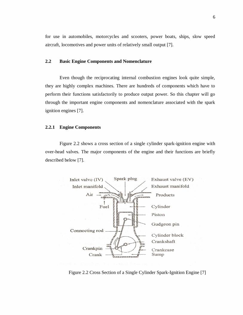
2.2.1 Engine Components
Figure 2.2 shows a cross section of a single cylinder spark-ignition engine with
over-head valves. The major components of the engine and their functions are briefly
described below [7].
Figure 2.2 Cross Section of a Single Cylinder Spark-Ignition Engine [7]