design of the helicopter-mounted flir system with …
TRANSCRIPT

Proceedings of the 9th ASAT Conference, 8-10 May 2001 Paper ST-14 495
Military Technical College, Kobry El-Kobbeh,
Cairo, Egypt
9th International Conference On Aerospace Sciences 8
Aviation Technology
DESIGN OF THE HELICOPTER-MOUNTED FLIR SYSTEM WITH FOUR-AXIS GIMBAL STABILIZATION
Haeng Bok Lee*
ABSTRACT
The Helicopter Forward Looking InfraRed (HFLIR) system is a lightweight, multipurpose, thermal imaging sensor for pilotage/navigation, surveillance, search-and-rescue, automatic tracking and targeting. It is a four-axis gimbal assembly, gyrostabilized in both azimuth and elevation. Design conditions for the gimbal assembly include operation and non-operational inertial, thermal, and dynamic loads. Design goals centered on augmenting stiffness and reduce weight to achieve relatively high modal performance, and also a study was performed to select key components in the gimbal hardware that are essential to meeting the performance objectives. A finite element model was used to maximize the fundamental frequency and select the best configuration the inner gimbal assembly of the turret FLIR unit (TFU). As a result, the fundamental frequency of the gimbal assembly met the design and performance requirements and was selected to meeting the performance objectives include torque motors, bearings, seals and position sensors.
KEYWORDS
Turret FLIR Unit, Inner Gimbal Assembly, natural frequency, vibration test
1. INTRODUCTION
Electro-optical tracking and pointing systems require precision stabilization of the line of sight in order to maintain the imaging sensor resolution and to precision point. The design of these systems requires an integrated optical sensor sensitivity and resolution, field of regard, slew rates and pointing, mechanical, electrical design effort to achieve the required line of sight stability, accuracy. The Helicopter Forward Looking InfraRed (HFLIR) is a helicopter-borne tracking system. Its goals are to perform search-and-rescue target detection and are matched to the night flying requirements for helicopter operations. The HFLIR system comprises the
* Technology Research Center, Agency for Defense Development, P.O. Box 35-5, Yuseung, Daejon, 305-600, Korea.

Proceedings of the 9m ASAT Conference, 8-10 May 2001 Paper ST-14 498
following four units, that is Turret FLIR Unit (TFU), System Electronics Unit (SEU), Multifunction Display Unit (MFDU) and Multifunction Control Unit (MFCU). The TFU employs a four-axis gimbal system, with an azimuth and elevation as the inner gimbal and the outer gimbal. The four-axis gimbal system are outer coarse gimbals, coarse elevation (CEL) and coarse azimuth (CAZ) motion, and inner fine gimbals, fine elevation (FEL) and fine azimuth (FAZ) motion. The outer two-axis gimbal consists of a coarse azimuth drive assembly and a coarse elevation yoke that supports and drives the inner two-axis gimbal assembly. The yoke is comprised of the structure of the azimuth bearing/motor housing and a pair of devises mounted to the ends of the beam structure. The coarse azimuth drive is supported by a cylindrical inner housing and utilizes a pair of angular contact ball bearings to support the outer housing and coarse elevation yoke, The elevation drive consists of left and right support devises, bearing assembles, and the elevation drive torque motor with its mounting. The inner two-axis gimbal consists of a fine azimuth drive assemblies and a fine elevation drive assemblies, and each drive assembly is mounted at right, left, upper and lower center positions around an inner gimbal frame. In the inner gimbal, directly coupled DC torque motors drive the gimbal about the azimuth and the elevation axis These torque motors are able to provide a gimbal acceleration of 90°/sec2 at airspeeds in excess of 300km/hr, and a slew rate of 60°/sec. The structural parts of the turret are aluminum castings except for the bearing attachment areas. The TFU contains the electronic, optical, and mechanical elements required for thermal imaging and for directing and stabilization the sensor line of sight. The stabilized four-axis gimbal provides isolation from sources of image motion' and jitter, allowing for maximum performance of the imaging sensor. The TFU consists of the thermal imager assembly (FLIR Sensor), which collects IR scene radiation and electro-optically converts the scene to a raw video signal, electro-mechanical drive elements of the gimbaled turret that point and stabilize the sensor's LOS, a hermetically sealed enclosure that shields the sensor from the environments. The FLIR Sensor is mounted on an optical bench of an inner gimbal assembly for TFU. The gimbal sybsystem provides movement and stabilization of the TFU; its major components are the torque motors, bearings, position sensors, seals, gyroscope and supporting structures. The azimuth travel of the LOS provided by the turret is continuous 360 degrees, and the elevation travel is 45 degree down and 120 degree up, providing complete hemispheric coverage of the area surrounding the vehicle.
2. SYSTEM REQUIREMENTS
The system requirements used to provide guidance for designing the gimbal mechanical, electrical components and supporting structure. The basic requirements of the HFLIR are:
- The HFLIR shall be capable of tracking a target with a line of sight rate of 60°/sec and an acceleration of 90°/sec2 Field of Regard -42° to 120° of elevation angle with full azimuth coverage 360°.
- The HFLIR TFU weight shall be less than 30kg. - The structure of the HFLIR TFU must have sufficient stiffness so that the
first structural mode is 1001-lertz, minimum.

Proceedings of the 9th ASAT Conference, 8-10 May 2001 Paper ST-14 497
3. MAJOR COMPONENTS SELCTION
Key components in the TFU hardware that are essential to meeting the performance objectives include a torque motors with low hysteresis for providing torque about the azimuth and the elevation axis, a bearing for supporting the gimbal assembly, an accurate lightweight capacitive pickoff device for angular measurement about the azimuth and the elevation axis of the inner/outer gimbal, and the selection of seal parts to insure waterproofing.
3.1 Torque Motor Selection The torque motors are a conventional brush type design using samarium magnets for maximum performance and small size. The outer gimbal has two torque motors for driving azimuth and elevation motion, also the inner gimbal do. The torque motor performance data are summarized in Table 1.
ue Motor Performance Data FEUFAZ/CEL CAZ
Peak Torque,Tprb-ftj 140 700 Power at Tp, Pp[VV] 83 102 No Load Speed, triNarad/s] 80 19 Elect. Time Constant, TeIrnsi 0.0002 0.0004 Voltage at Tp, VpM 22.6 20.9 Current at Tp , 1p[A] 3.71 5.3.4 Resistance, R[D] 6.1 3.9 Torque Sensitivity, Krilb-ft/A1 37.7 131 Back E.M.F., KB[V/rad/s] 0.266 0.92
3.2 Bearing An important feature that has been incorporated into the gimbal design is the use of custom bearings for supporting the gimbal assembly. The bearings are self-aligning, exhibit low friction and provide high load capability. The bearing data are summarized in Table 2.
Table 2. Bearing Data Load Capabilities Friction
Torque Preload Radial Thrust
FEL Right Bearing 1401b 3601b 0.03Nm 15- 201b FEL Left Bearing 1401b 360lb 0.03Nm 15- 20Ib FAZ Upper Bearing 1401b 360Ib 0.03Nm 15- 201b FAZ Lower Bearing 3101b 7801b 0.03Nm 15- 20Ib CEL Right/Left Bearing 7261b 1830lb 0.035Nm -
CAZ Bearing 9101b 26401b 0.3Nm 100lb
3.3 Seal An immersion test method of the TFU is that three times immersion for lowermost point of the TFU is 1±0.1m below the surface of the water, 30minutes immersion period. The seal data are shown in Table 3.

Proceedings of the r ASAT Conference, 8-10 May 2001 Paper ST-14 498
Table 3. Seal Data Dimension Pressure Friction
CEL Seal 012" 20kpa <0.04Nm CAZ Seal 03.1" 20kpa <0.3Nm
3.4 Position Sensor A proven aerospace qualified coarse resolver was selected to measure angular motion about the azimuth and elevation axis. These units have a high resolution, 8:1 speed, fine winding, with accuracy of 20 arcseconds. These transducers were selected based on its weight and size. It resolves over the angular range of 360 degrees of azimuth and elevation axis.
3.5 Gyro The selected gyro in the turret belongs to the Dynamically Tuned Gyro. The DTG is a two-axis, spinning mass, inertial rate sensor. The use of a single two-axis DTG for line of sight stabilization is considered a small volume and low cost solution when compared with the once common pair of single-axis rate integrating gyros.
3.6 Slip Ring A slip ring assembly was incorporated in coarse azimuth so that continuous rotation could be maintained. Drive mechanism wires and position sensor wires were required to go through the slip ring assembly.
4. STRUCTURAL DESIGN REQUIREMENTS
Natural frequencies must be tailored to avoid harmful coupling of modes and resonant amplifications. For a minimum frequency of the TFU structure, greater than 100Hz for major mode is desired. Further design requirements were categorized based on anticipated operational and non-operational flight environments. The TFU was designed to withstand a non-operational shock input of 15g acting for 11msec. The non-operational thermal environment ranged from -35° C to +50°C. Table 4. Summarizes of the critical design requirements that were addressed.
Table 4. Structural Design Requirements Vibration MIL-STD-810E Shock 15g, 11msec, Half-sine .ulse Temperature -35° C to +50°C The first significant structural mode > 100Hz
4.1 Mass and Center of Gravity Requirement The total TFU mass requirement is less than 30kg, and the vertical center of gravity requirements is no greater than 150mm above the center interface, and within a 2mm radius of the centerline for center.
4.2 Frequency Requirement The HFLIR TFU must have sufficient stiffness so that the first structural mode is 100Hertz, minimum.
Proceedings of the e ASAT Conference, 8-10 May 2001 Paper ST-14 499
5. STRUCTUAL ANALYSIS
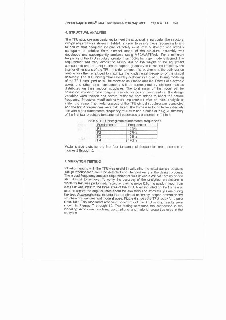
The TFU structure was designed to meet the structural, in particular, the structural design requirements shown in Table4. In order to satisfy these requirements and to assure that adequate margins of safety exist from a strength and stability standpoint, a detailed finite element model of the structural assembly was developed and subsequently analyzed using MSC/NASTRAN. For a minimum frequency of the TFU structure, greater than 100Hz for major mode is desired. The requirement was very difficult to satisfy due to the weight of the equipment components and the unique sensor support geometry in a volume limited by the interior dimensions of the TFU. In order to meet this requirement, the optimization routine was then employed to maximize the fundamental frequency of the gimbal assembly. The TFU inner gimbal assembly is shown in Figure 1. During modeling of the TFU, small part as will be modeled as lumped masses. Effects of electronic boxes and other small components will be represented by discrete masses distributed on their support structures. The total mass of the model will be estimated including mass margins reserved for design uncertainties. The design variables were resized and several stiffeners were added to boost the natural frequency. Structural modifications were implemented after an initial analysis to stiffen the frame. The modal analysis of the TFU gimbal structure was completed and the first 4 frequencies were calculated. The frame was found to be extremely stiff with a first fundamental frequency of 125Hz and a mass of 29kg. A summary of the first four predicted fundamental frequencies is presented in Table 5.
Table 5. TFU inner gimbal fundamental frequencies Fundamental Frequencies F1 125Hz F2 127Hz F3 139Hz F4 176Hz
Modal shape plots for the first four fundamental frequencies are presented in Figures 2 through 5.
6. VIBRATION TESTING
Vibration testing with the TFU was useful in validating the initial design, because design weaknesses could be detected and changed early in the design process. The modal frequency analysis requirement of 100Hz was a critical parameter and also difficult to achieve. To verify the accuracy of the analytical predictions, a vibration test was performed. Typically, a white noise 0.5grms random input from 5-500Hz was input to the three axes of the TFU. Gyro mounted on the frame was used to record the angular rates about the elevation and azimuthally axes during the test. Accelerometers, mounted to the gimbal assembly, helped determine the structural frequencies and mode shapes. Figure 6 shows the TFU ready for a pure sinus test. The measured response spectrums of the TFU testing results were shown in Figures 7 through 12. This testing confirmed the confidence in the modeling techniques, modeling assumptions, and material properties used in the analyses.

Proceedings of the 9th ASAT Conference, 8-10 May 2001 Paper ST-14 500
7. SUMMARY
A study was performed to select key components include the toque motors, bearings, position sensors and seals. The primary resonance and mode shapes of a TFU inner gimbal frame were evaluated with a MSCINASTRAN finite element model solution and test results were obtained from 0.5g sine sweeps. A design goal a first mode resonant frequency of a 100Hz was achieved and the design primary driver of a weight under 30kg was realized. Results showed excellent correlation between analysis and data on the first four modes.
REFERENCES
1. K.B. Doyle, V.J. Cerrati, S.E. Forman and J.A. Sultana, Optimal structural design of the Airborne Infrared Imager, SPIE Optomechanical and Precision Instrument Design, Vol.2542, pp11-15, 1995
2. P.R.Yoder, Jr., Opto-mechanical Systems Design, Marcel-Dekker, New York, 1986
Figure 1. TFU Inner Gimbal Assembly

Proceedings of the 9th ASAT Conference, 8-10 May 2001 Paper ST-14 501
TITLE N:118fl. MOCE OF It-COTS IL 8E5LLI5: 4-501110"1.MXIE.4,1".126.74512,-N100E 94VE MIX; 4 FFEO: 126.7475 DISELFEEMENT - 11 0.00E-E00 m90: 20E-01 ocrORMTICN: 4-510 10.1,14017E84,F-126.74.12.EMVEE 918E MOLE: 4 FICO: 126.705 DISPLACEMENT - MFG MIN: 0.00C400 WC: 9.20E-01 MEM OF FEE: GFIV1
88LLE OPTION:PC1
9.26E-0
3.76E-0
3.36E-0
2.94E-13
2.52E-0
2.16E-0
1.68E-0
1 .26E-0 E-0
0.39E-0
4.22E-B
Figure 2. TFU Inner Gimbal Frame 1s) mode (125Hz)
TITLE - NORMA. PIKE Of 8-EOT5 1G FfeLlTS: 5-9-18 IDEI,M012E.5,1,139.051.12,-,NOIE 948E MIZE: 5 FEE0 133.0514 0191FEEMENT - F4,‘ MIN: 0.00E456 NU: 3.00E-01 BEECRNITICN: 5-51.0 113.1.190E3.5.1-.139.0511.1j,-0100E 988E COLE; 5 FLEE 139.0514 13192LFICEM4I - Mt. MIN: 61.00E4610 11310 3.60E-01 FREPE CF REF, MEM'
MLLE OPTIGN:FET
3.82E-0
3.42E-0
3.09E-0
2.66E-0
2.28E-0
1.90E-0
1.52E-0
1.14E-0
7.66E-0
3.80E-0,
Figure 3. TFU Inner Gimbal Frame 2"d model (127Hz)

ilitf 63664 407.6 of 10E075 10 4644.416E 3-51101041,11013E43,0•115.35502, -E6016 9412E FOIE: 3 o360: 125.094 01914116614041 - MC. nINE 8.61E468 666 3.721-61 LEF00197101E 3-516 11241.19347.F•125. 35912.-WOLF 9461 433164 3 FFEDE 125.3594 01511044-61163n • WC 006 e.anc.ize eax, 3.716-e. FPREE Of ICE: F-21
VILE 461190 F1/
7.39E.
3.‘0E-6
2.64E-0
1.71E-0
Proceedings of the 9th ASAT Conference, 8-10 May 2001 Paper ST-14 502
Figure 4. TFU Inner Gimbal Frame 3th mode (139Hz)
71111 942409* 110116 OF 9-1005 II 6E5_676: 6-9,e 1641X0611•6.F4173.4961-12. -/300E MOE: 6 160E01 179.4962 0191.14121O411143 - 0166 1100 0,1266406 rfixE 5.27E-61 016001614T1ON: 6-5136 1110 1,7191:646,44179.4961-12, -M00E 91s1PE 19-1E: 6 3510: 179.4962 1319-11:02711641 - ISC MINE 0.62E400 NIX: 5.27E-01 031176 fF 363: Wel
VALUE 0P110e0, PC'
5.27E-0
1.27E-0
3.69E-0
3E16E-0
2.641-0
2.11E-6
1.56E-0
I .05E-0
5.27E-0
0E0E6E10
Figure 5. TFU Inner Gimbal Frame 4th mode (176Hz)

Figure 6. Photograph of TFU Vibration Test Set-Up
Acceleration es Frequency (FAZ Frame, X Ax(r)
iiitilkiSisMt MiSillik/Tili" 2L4NagNM'ddirMi IMENNEEMESIMPRIONO
'.11t6EAT■:--r" '.7711111M.,
1 **,E.
liDt -'' 0 100 200 300 300 SOO 100
Frequency (Hz)
1E302
• LE•01
12300
• 14-01
< 1E-02
1E-03
Proceedings of the 9th ASAT Conference, 8-10 May 2001 Paper ST-14 503
Figure 7. Test Result of FAZ Frame, X-Axis Direction

Acceleration vs Frequency ( FEL Frame, X Axis)
Ion 209 3W SCIO sca SW
Frequency (Hz)
lE •02 "29 1E•al g 1.Excin
LE-tu 1E-02 I.
13 1£ -03
Acceleration vs Frequency (FEL Frame, Y Axis)
CISIMLWIlii4/11.41itaalPI Faiiiiirlt'c'.4t1E6,, -71::Mthtthell
0 100 200 300 400 500 610
Frequency 1140)
S' 1.2.02 1.2.01 C
e •in ' x.c-ua 1..E -03
Proceedings of the 9m ASAT Conference, 8-10 May 2001 Paper ST-14 504
Figure 8, Test Result of FEL Frame, X-Axis Direction
Acceleration vs Frequency (FAZ Frame, Y Axis)
0 100 200 300 400 500 600
Frequency (Hz)
Figure 9. Test Result of FAZ Frame, Y-Axis Direction
Figure 10. Test Result of FEL Frame, Y-Axis Direction

Acceleration vs Frequency (FAZ Frame, Z Axis)
NNIRPIWEMIVEIRNSSBDEIIIEWI WilleSIWAMItiFfintfillIMSF illeWilitOitffiffr ig WEE MitifilMEMEintit BSCUte 11111NNUMME171liiiiielNI Ma
100 200 300 400 500 600
Frequency (I-1z)
1.E
2 1E .ea y 1E-01
1E-02
1.0 -03
a
Acceleration vs Frequency (FEL Frame, Z Axis)
011111412196 LIZNAZZA IMMILIMINUINItilitifila iiiiiMill Yisr 51zinvati t-Ifitw mho SIONCIMMIZINOliiialNitili
WWI IIMININIONINNERMON 100 200 300 WO 500 WO
Frequency (Fe)
1E.02
c0 1E.01 I.E.o)
8 1.E-oe 1E-03
Proceedings of the 9. ASAT Conference, 8-10 May 2001 Paper ST-14 505
Figure 11. Test Result of FAZ Frame, Z-Axis Direction
Figure 12. Test Result of FEL Frame, Z-Axis Direction