design of solid engine mounts for a 115 mercury/mariner mount article new.pdf · design of solid...
TRANSCRIPT

Design of Solid Engine Mounts for a 1993 115 Mercury/Mariner
Daniel W. Rickey, Bill McDonald, Ian Paul, Bob Miller
Winnipeg, Manitoba CANADA
2001-07-24
IntroductionThe factory rubber engine mounts work quite well for the average low-speed boat. However, once speeds exceed 100 km/h these soft mounts will result in undesirable handling behavior. Typical is a chine walk where the entire boat rocks from side to side. In addition, the mounts can result in a very unpleasant change in direction when the throttle is released at high speeds. Replacing the factory mounts with solid aluminum mounts is a must for any high speed boat.
For most V6 outboards it is a simple matter to order up and install solid aluminum engine mounts. Unfortunately, if you are using a slightly unusual engine you will be faced with designing and making your own mounts. In this article, we describe the design and manufacture of solid engine mounts for an inline four cylinder Mercury. This engine easily pushes a HydroStream Viking to a 100 km/h resulting in the unpleasant and dangerous handling characteristics described above. Ready-made solid mounts do not exist for this engine.
In order to get at the mounts, the power head and lower unit must be removed first. If you are not familiar with your engine, I would recommend purchasing the factory shop manual (not a third party manual).
1

Figure showing the old lower mount with the cover plate in place. Note that the mount has been marked with whiteout because it is easy to install a mount backwards.
Figure showing the old lower mount with the cover plate removed.
2

The lower mount after being removed from the housing. Note that there is a small but important offset between the inner and outer cylinders. The whiteout indicates the front.
This is the old top mount with its four bolts removed. Notice the locating pin boss to the left of the mount.
3

This is the housing after the top mount has been removed. There is only a single pin for locating the mount. Note the lack of machined surfaces.
4

The underside of the original top mount. The only machined surface is a hole for a locating pin. The purpose of the pin is not clear, e.g. is it for alignment during assembly or is it to keep the mount from moving around under load? The shape of this mount is fairly complex, but it can be simplified somewhat.
Design of Solid MountsThe design of the lower mounts is quite straight forward. Because these mounts are clamped in place, their size is important. The dimensions of the stock top mount were obtained with a digital height guage on a granite surface block. In our case we added a fair bit of material to increase the strength of the mount. In the end the mount was about as large as it could be and still fit. The mounts were machined on a lathe.
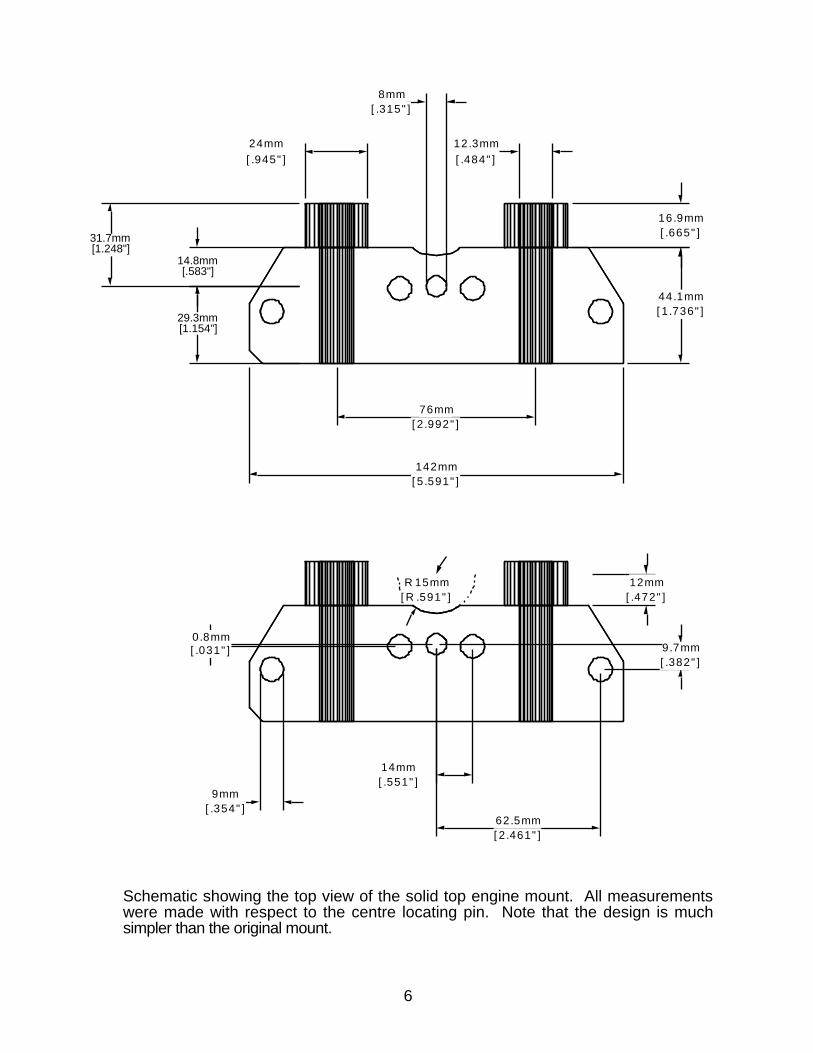
The stock top mount is a fairly complex design. We used the digital height guage on the granite surface block to obtain the dimensions. In this case drill bits were placed in the holes to measure their locations. Because the stock mount had only one machined surface (a locating hole) all measurements were made with respect to it. The design of the top mount was simplified by adding material where there was room for it in the midsection. Machining was performed on an NC-mill but could have easily been done on a conventional mill with a rotary table.
5
6
R 15mm[R .591"]
0.8mm[.031"] 9.7mm
[.382"]
14mm[.551"]
62.5mm[2.461"]
12mm[.472"]
9mm[.354"]
142mm[5.591"]
44.1mm[1.736"]
16.9mm[.665"]
76mm[2.992"]
24mm[.945"]
12.3mm[.484"]
8mm[.315"]
29.3mm[1.154"]
14.8mm[.583"]
31.7mm[1.248"]
Schematic showing the top view of the solid top engine mount. All measurements were made with respect to the centre locating pin. Note that the design is much simpler than the original mount.

7
28.5mm[1.122"]
24mm[.945"]
12.3mm[.484"]
76mm[2.992"]
Schematic showing the front view of the solid engine mount.
Here is a nice rendered view of the solid top engine mount.

44.35mm[1.746"]
12.25mm[.482"]
Schematic showing the solid bottom engine mount. The design is quite simple.
Here is a nice rendered view of the solid bottom engine mount.
8
29.75mm[1.171"]
22.6mm[.890"]
23.9mm[.941"]
22.7mm[.894"]

Here is a comparison of the lower mounts. The housing design required that the mount be tapered on one side. The front of the solid mount was left straight for added strength.
The new lower mount in place showing why the taper is required.
9

Here’s the solid lower mount bolted in. Because the mount sits in a cast, rather than machined, surface there is some variation in size. On one side of this engine, the mount fit in very easily. On the other side, the mount had to be machined down a small amount. This problem was noted with the stock mounts as well.
This is the underside of the solid top mount. The design is much simpler than the original mount.
10

The top mount in position shows the tight clearance with the locating pin boss on the left.
This is the top mount bolted in place. The original large washers were used.
11

The lower mount bolted in place. All of the original hardware was used.
12
The last step is to bolt the power head on. Use a new gasket and make sure the shifter rod is in place first.

DiscussionInitial testing resulted in a couple of observations. The first is expected in that the boat vibrates a fair bit more than it used to. This is easily felt through the steering wheel and may add a bit of extra fatigue on a very long ride; however I found an hour drive to be not a problem. The second observation is that the boat is much better behaved when releasing the throttle at high speed. Previously, the boat would turn rather sharply when backing off the throttle. Now it stays straight and just slows down. The chine walk is reduced a bit as well: however, a jack plate was added at the same time as the solid mounts complicating the results.
- the end -
13