design of slotline ring resonator 報告人:施冠州 日 期: 2003/02/27
TRANSCRIPT
Design of Slotline Ring ResonatorDesign of Slotline Ring Resonator
報告人:施冠州日 期: 2003/02/27

大綱大綱簡介設計原理設計步驟結論參考資料
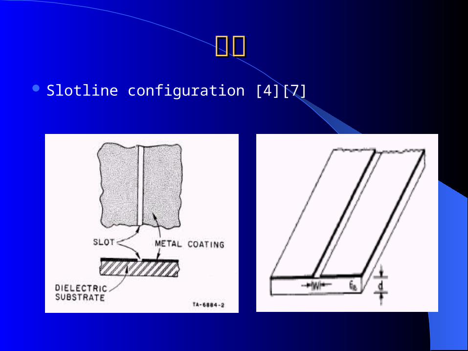
簡介簡介 Slotline configuration [4][7]

FIELD DISTRIBUTION IN CROSS-SECTION VIEW [7]

設計原理設計原理 Circuit configuration of the slotline ring resonator
with different coupling schemes[1,2,8]
Slotline ring

The frequencies of the slotline ring resonator are determined by
2πR = nλg [1,2]
• R is the mean radius of the slotline ring
•λg is the slotline guide wavelength
• n is the mode number

The resonant frequency of a ring with a mean radius R can be calculated by
eff
pg
f2
n
f2
n
2
nR
cv
• εeff is the effcetive dielectric constant
• c is the speed of light

參數介紹 (Harmonica)
G : Gap width
Z0 (Z0) : Transmission line impedance
F : Analysis frequency
ER(εr) : Relative dielectric constant
H : Substrate thickness
HL : Distance between bottom of substrate and ground
HU : Cover height above substrate
A : Width between sidewalls

Harmonica
Microwave office
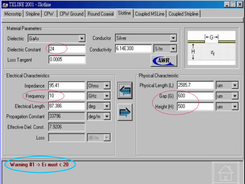
For synthesis of slot line transmission lines, the parameters Z0, H, HU, HL, A, F and ER must be entered prior to clicking the Synthesis button. The width, G, will be computed. T/G < 0.02 (T is the total conductor thickness)
εr must be 20≦
the parameters G, H, F and ER must be entered to clicking the button. The impedance, Z0, will be computed or enter the parameters Z0, H, F and ER to clicking the button. The width, G, will be computed.

w : Gap width
Z0 : Transmission line impedance
F : Analysis frequency
εr : Relative dielectric constant
h : Substrate thickness
λ0 : free-space wavelength
λg : slot mode wavelength

The equations for design are from [3]~[5]
•9.8≦εr 20.0 high dielectric constants≦(1)0.02 ≦ w/h 0.2 (2)0.2 ≦ ≦ w/h 1.0≦(3)0.01 ≦ h/λ0 0.25/(≦ εr –1.0)0.5
•3.8≦εr 9.8 intermediate dielectric constants≦(1)0.0015 w/ λ≦ 0 0.075≦(2)0.0075 w/ λ≦ 0 1.0≦(3)0.006 ≦ h/λ0 0.06≦
•2.2≦εr 3.8 lower dielectric constants≦(1)0.0015 w/ λ≦ 0 0.075≦(2)0.0075 w/ λ≦ 0 1.0≦(3)0.006 ≦ h/λ0 0.06≦

0
0r
0r
r
2r
6.0
0rr0
w
h735.0
h0.100ln)
h
w)(12.2(51.0
0.2876.0hw
hw
)0.2250.4123.36(
)w
)(37.319.638(15.26.73Z
•3.8≦εr 9.8 , ≦ 0.0015 w/ λ≦ 0 0.075≦

The expressions obtained by curve fitting the numerical results.
2
0
geff
2
00
2r
0
rr
]})
w10006.9(w
65.36.4)[
hln(01.0
435.0hw
)h
w(0322.0ln277.09217.0{

approximations for slot line [6] [7]
2
1reff

設計步驟設計步驟substrate – h (thickness) , εr (dielectric constant) film thicknessresonant f (Hz) coupling methods (cpw,slot,microstrip……)
Z0 () → w (line width) → εeff → R
By eq. or microwave
office or harmonic.
By equation

範例範例 G-10 : h =15 00μm , εr =4.6 film thickness = 100 μm resonant f = 2G Hz coupling methods → CPW Z0 = 50 → CPW : w=1500μm, g=410μm
Z0 = 85 → slotline : G=530μm, εeff = 1.913279, R=17259μm .
coupling gap=546μm

The CPW-fed Slotline Ring Configuration
Slotline ringCoupling gap
CPW
結論結論 The slot transmission line has a simple planar geometry
that is compatible with microwave integrated circuit. Various coupling methods were devised for different
applications. The slotline annular ring element with the advantages of
good performance and ease of adding series and shunt components.
Slotline types of annular ring elements have been developed as circuit components for the resonator, filter, latching phase shifters and hybrid coupler.

參考資料參考資料[1] Chien-Hsun Ho; Lu Fan; Kai Chang,” Slotline annular ring elements and their
applications to resonator, filter and coupler design”, Microwave Theory and Techniques, IEEE Transactions on , Volume: 41 Issue: 9 , Sep 1993 Page(s): 1648 –1650.
[2] Navarro, J.A.; Lu Fan; Kai Chang,” The coplanar waveguide-fed electronically tunable slotline ring resonator”, Microwave Symposium Digest, 1992., IEEE MTT-S International , 1-5 Jun 1992 Page(s): 951 -954 vol.2.
[3] Brian C. Wadell,'Transmission Line Design Handbook",1991 ARTECH HOUSE,INC.page(s):156~161.
[4] Garg, R.; Gupta, K.C.,” Expressions for Wavelength and Impedance of a Slotline (Letters)”, Microwave Theory and Techniques, IEEE Transactions on , Volume: 24 Issue: 8 , Aug 1976 Page(s): 532 –532.
[5] Janaswamy, R.; Schaubert, D.H.,” Characteristic Impedance of a Wide Slotline on Low-Permittivity Substrates (Short Paper)”, Microwave Theory and Techniques, IEEE Transactions on , Volume: 34 Issue: 8 , Aug 1986 Page(s): 900 –902.

[6] Cohn, S.B.,” Slot Line on a Dielectric Substrate”, Microwave Theory and Techniques, IEEE Transactions on , Volume: 17 Issue: 10 , Oct 1969 Page(s): 768 –778.
[7] Cohn, S.B.,” Slot Line - An Alternative Transmission Medium for Integrated Circuits”, Microwave Symposium Digest, 1967 G-MTT International , Volume: 68 Issue: 1 , May 1968 ,Page(s): 104 –109.
[8] Kai Chang,"MICROWAVE RING CIRCUITS and ANTENNAS",1996 by John Wiley & Sons, Inc.