design of reinforced concrete structures prof. nirjhar ... · calculation of deflection. and it is...
TRANSCRIPT

Design of Reinforced Concrete Structures
Prof. Nirjhar Dhang
Department of Civil Engineering
Indian Institute of Technology, Kharagpur
Lecture - 30
Deflection of RC Beams
(Refer Slide time: 01:46)
Well, so today we shall learn how to calculate deflection of rc beams reinforced concrete
beams. If we take any the formula for calculation of deflection is very easy. If we take a
simply supported beam, if we take a simply supported beam of say span L uniformly
distributed load W. The deflection the central deflection say delta max that is equal to 5
by 384 W L to the power 4 by EI.
We do not have any confusion regarding W the uniformly distributed load over the span
span L. But, we are having problem that E and I because for reinforced concrete when
you are talking say reinforced concrete we have to calculate say E and i. So far, we have
designed for the cracked section. That means, the only complacent part that is uncracked
but, bottom wherever we have reinforcement that crack may appear.
So what is the value of E and what is the value of I that is the major difficulty here so for
the formula concept. Formula looks very simple but, providing that proper value of E
and I we will give result that 1 differs significantly; if we could not provide E and I. So

we shall find out so what is the problem let us find out. So what are the difficulties?
Difficulties in calculation, number 1: let me write down, variation in flexural stiffness
that means E I along the span owing to but, for owing to the uncertain nature and extent
of cracking.
So, we are faced difficulties because variation in flexural stiffness E and I that EI that is
the flexural stiffness along the span along this span owing to the uncertain nature and
extent of cracking. Because we do not know cracking cracking also not uniform and also
that uncertain wherever the crack will; there is no uniformity. So, this is 1 of the cases.
Number 2: variation in shrinkage and creep these are the 2 properties we have told in the
very beginning of our class. Owing to what for it happens?
Number 1: it may happen for curing that how you have cured, then humidity, exposure,
composition of concrete and also age at loading. That when you are loading this structure
it depends on that also. So, these are the difficulties that we have faced due to these two
cases that flexural stiffness you do not know the proper ei it is not uniform like steel.
And number 2: due to shrinkage and creep and it may happen due to say curing
condition. That means, after the casting how it is cured humidity exposure condition
whether mild or that different exposure conditions.
Then composition of concrete what grade of concrete you are using that is it also matters
and also age at loading. When you are loading that what is the age of the concrete
depending on that. So, this formula we shall use the same formula only we have to
provide that proper E and I.

(Refer Slide Time: 06:39)
We also write down the same formula say delta. Let us write down it as 5 by 384 then W
L to the power 4 EI. And we can make it as I say F by EI F means here in this case what
is f? F equal to you can write down 5 by 384 wl to the power 4 and it is this 1 it means
we can say due to load span arrangement. So, these value we are getting it here that f
equal to 5 by that is if it is uniformly distributed load over a simply supported beam, then
we shall get these factor. So, EI is that value F we are getting almost say we can say
determinate the other part only we are facing difficulty.
So we can write down one more example we can show. Let us say, uniformly loaded by
moment bending moment that is uniform moment over the whole section. So, if we take
a beam uniformly distributed load say simply supported beam and moment is M that is
uniform bending moment. So, we can find out delta max delta max will be equal to, for
this case the central deflection delta max that one we shall get it as ML square by 8 EI
this is the one deflection we shall get it.
We can find out also here that for these from I do not know whether you know the
moment area theorem. So ,according to that also you can find out deflection otherwise
you can find out the other way also but, any way delta max is equal to ML square by 8
EI. So we can write down it as 1 by 8 times M by EI times L square which comes as
0.125 M by EI times L square. In other way, we write down this equation as beta times I
times L square.

Beta means, this coefficient this coefficient is equal to 0.125 and sae, that is that
curvature because psi equal to m by EI or 1 by o that 1 we can say and L is the span. So,
we can write down in this fashion also that formula we can write down. Infact what we
do actually these value we use it for this shrinkage. Indirectly we shall supply these value
beta psi all those value we shall supply and on the basis of that we can find out what is
the deflection due to shrinkage.
(Refer Slide time: 09:35)
So, before going to that let me give the reference that is your annex C. Annex C, that is
calculation of deflection. And it is in page 88 IS 456 2000. There is one term is called
that is you say c 2 clause c 2 that is your short term deflection short term deflection. And
let me give you the formula that whatever given that I effective equal to Ir please note
there are so many unknown things we are writing. Ir minus Mr by M times z by d times 1
minus x by d times bw by b.
So, ir atleast let me write down few things ir that is second moment of area of the
cracked section. Ir this is ir that is the one second moment of area of the cracked section.
Mr that is cracking moment mr that is cracking moment and which will be equal to fcr
times Igr 1 more term divided by yt. Fcr modulus of rupture and that we shall take it as
0.7 root bar fck. Fck again you know that is characteristic strength 0.7 root fck 0.7 root
fck we shall get it that clause that reference I should give IS 456 that is clause 6.2 0.2.
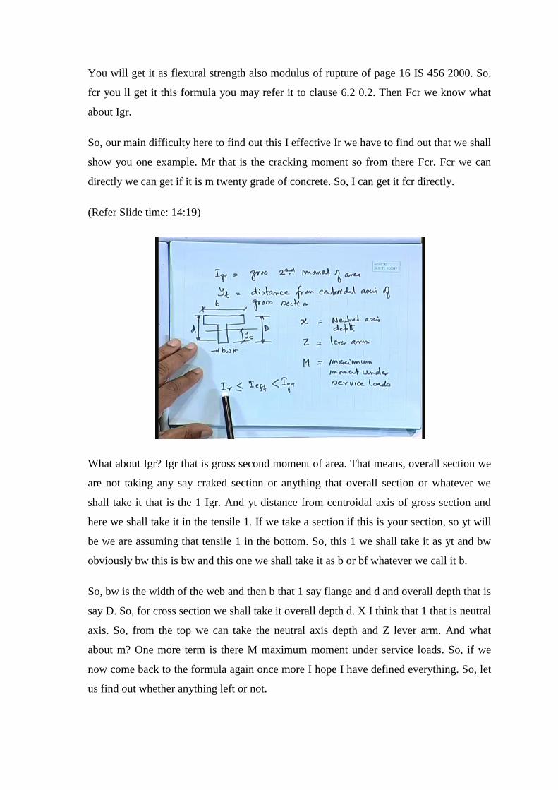
You will get it as flexural strength also modulus of rupture of page 16 IS 456 2000. So,
fcr you ll get it this formula you may refer it to clause 6.2 0.2. Then Fcr we know what
about Igr.
So, our main difficulty here to find out this I effective Ir we have to find out that we shall
show you one example. Mr that is the cracking moment so from there Fcr. Fcr we can
directly we can get if it is m twenty grade of concrete. So, I can get it fcr directly.
(Refer Slide time: 14:19)
What about Igr? Igr that is gross second moment of area. That means, overall section we
are not taking any say craked section or anything that overall section or whatever we
shall take it that is the 1 Igr. And yt distance from centroidal axis of gross section and
here we shall take it in the tensile 1. If we take a section if this is your section, so yt will
be we are assuming that tensile 1 in the bottom. So, this 1 we shall take it as yt and bw
obviously bw this is bw and this one we shall take it as b or bf whatever we call it b.
So, bw is the width of the web and then b that 1 say flange and d and overall depth that is
say D. So, for cross section we shall take it overall depth d. X I think that 1 that is neutral
axis. So, from the top we can take the neutral axis depth and Z lever arm. And what
about m? One more term is there M maximum moment under service loads. So, if we
now come back to the formula again once more I hope I have defined everything. So, let
us find out whether anything left or not.

(Refer Slide Time: 09:35) So this is our formula we have to find out I effective and here
also there is no end to it. So I effective equal to Ir. Ir we have to find out for the cracked
section Mr cracking moment. We shall find out from here where igr is the for the cross
section it also we can calculate for the gross section. Z lever arm d effective depth x the
neutral axis depth bw width of the web and b width of the flange.
So, everything we know; so we have to find out. And here it doesnot end here there is 1
restriction and that I should say that Ir is should be that I effective and Igr. Then
whatever we are getting that I effective that whatever we are getting if it comes less than
Ir then you have to take it Ir that value we have to take it.
(Refer Slide Time: 18:02)
So, I think we can take one example that will be easier. Let us take one t section and let
us assume that we have designed it due to say your applied load. Now, you have to check
the deflection. So, this is 2200 let us say that the slab depth which is the depth of the
flange also 125. Let us say, we have got 325 bar and these depth that is say 575 overall
depth 700 concrete M 2. We are talking say service load steel Fe 4 1 5 dead load span 7.5
meter and simply supported.
Then d equal to dead load fifteen kilo newton per meter this is the service load not the
factored 1. When we talking the deflection that 1 we are talking say service load. Live
load 10 kilo Newton per meter. D equal to 700 overall depth 700 minus cover minus 25
by 2 it comes as 662. 5 millimeter. Area of steel that is 3 into pie by 4 into 25 square so 3

into 491 1 4 7 3 square millimeter. M that is the moment we are getting it here. So, WD
plus WD that is the maximum moment.
For the simply supported case WL square by 8 which comes as equals 175.78 kilo
Newton meter. So, that Mr by M so this m that is the maximum moment under the
service load that we have got one component so far. So, let us find out so M we have got
it 175.78 kilo Newton meter. So, let us find out that Ec.
(Refer Slide Time: 21:24)
Ec equal to 5000 root fck in the new code in IS 456 2000 it is 5000 in the earlier code of
1978 it was 5 7 0 0. (Refer Slide Time: 18:02) So, moment we have got 175.78 kilo
Newton meter and area of steel you are getting 1 4 7 3 square millimetre. Effective depth
662.5 with clear cover 225 millimeter and that bar we have used say 25 dia so which we
have got it. These one you can say that you have got this information everything from
your say either by working stress method or by limit state method. That you have got
these values.
Now, you are checking the deflection and which you will do it by say under working
stress condition that means under service load. So Ec we are getting here say 5000 root
fck and which comes as 2 2 3 6 1 newton per square millimeter. Modulus ratio that
modular ratio there is 1 more formula but, that we can use directly this formula also Es
by Ec. For steel it is this newtom per square millimeter and which we got it for concrete

from the flexural strength we are getting that is from characteristic strength we can find
out ec and which comes as 8.94. So modulus ratio 4 that we have got it 8.94.
Now, what about fcr fcr equal to 0.7 root fck already I have told you that is in clause 6.2
0.2 page 16. These value also you will get it in the same page page 16 the next clause of
IS 456 and which comes as 3.13 Newton per square millimetre. You will get it as the
flexural strength also modulus of rupture which is defined in the list of symbols in IS
456. Let us assume, x is less than 125 millimeter. I mean to say that your neutral axis
will be within your flange then our problem will be easier.
So, this your 125 that is the slab also we can say or depth of the flange. So, neutral axis
may be somewhere here. So this is your x. So, if that be the case so you can use the
transformed section it means half this is your b times x square that means b times x into
x by 2. B times x is the area times x by 2 that is the 1 we are taking with respect to the
neutral axis. That 1 should be equal to modulus ratio times ast this one will change the
transformed section this one will change the steel to the equivalent concrete section.
Times d minus x so I am getting this one with respect to this neutral axis and taking the
moment and from there we can get these values.
So, in our case in our case it will be half b is 2200 thats what we have given that in the
problem please I would like to refer it back, (Refer Slide Time: 18:02) this is 2200. So, b
and x I do not know so far so we have got it. So, 1 4 7 3 whatever depth, depth is 662.5
minus x. So, from this equation I can find out the value x. So, from this equation I can
get that value x.

(Refer Slide Time: 26:06)
So, let us just simply write down the equation x square plus 1.05 equal to 0. And x comes
as 83.27 millimeter less than 125 millimeter the assumption whatever we have done that
is correct; that means, it is coming within flange. Now, we can calculate the lever arm
lever arm working stress method. So 662.5 minus 83.27 by 3 and it comes as 634.75
millimeter. What about that Ir? Ir is the for the cracked section second moment of area of
cracked section. That one will be equal to let me write down the formula first b times x
square by 3. Let me draw a figure.
So, this is your b somewhere here we are having . So, b that means we are taking about
this neutral axis, So, b x square by 3 we are talking this portion so this is uncracked one.
Plus m times ast where it is ast here times d minus x whole square that means this 1 your
d so d minus x. So, this is your d minus x.
So, this is your that formula so I can write down it 2200 into 83.27 whole cube by 3 plus
m is 8.94 which we have computed times 1 4 7 3 the area of steel times 662.5. That
effective depth minus neutral axis depth 3.27 whole square which comes as 4.8414 into
10 to the power 9 millimeter to the power 4. So, this is your ir for the cracked section we
are getting this value.

(Refer Slide time: 29:00)
Now other part distance of centroid from tension fibre. So, this is 2200, this 1 your 125,
this is 575 overall depth, this is overall depth 700 the section which we are using this is
250. And we are interested to find out yt may be somewhere here. And yt will be equal
to because from the tension fibre and we are for the simply supported case it is at the
bottom. So, yt will be equal to 250 times 700 times 700 by 2 plus ... Let me write down
here 2200 minus 250 times 125 times 575 plus 125 by 2.
We are taking this portion this is 1 250 into 700 as if we are talking rectangle this
rectangle we are taking. So, 250 into 700 into 700 by 2 plus the remaining portion which
is 2200 minus 250. So, that means this portion times 125 that is the area remaining
portion times we are we shall get somewhere here. So, these depth that is your 575 plus
125 by 2 thats what I have written. So we have made it 2 parts: 1 part is that the
rectangular portion overall and the another 1 the remaining portion. So, 2200 minus 250.
Then we shall get it here divided by 250 into 700 plus 2200 minus 250 times 125 and
which comes as 517 millimeter. So, we have got yt and let us find out that Igr the gross
moment second moment of area. Gross second moment of area we can find out because I
know now that 517 millimeter this 1. So 250 times 517 whole cube by 3 that means, I am
talking about these portion this portion I am talking so with respect to this neutral axis.
So 250 into 517 whole cube by 3 plus let us take the whole so which is 2200 into 700
minus 517 whole cube by 3. I am taking this portion the whole minus 2200 minus 250

times these portion this portion. That means, I would like to remove this portion and let
me write down that 1 here as 700 minus 517 minus 125 that whole cube by 3. And which
comes as 1.588238 into 10 to the power 10 millimeter to the power 4.
So, you can get Igr this value that means I am taking the only this portion in the bottom
of the neutral axis. Then I am taking the top portion minus this portion this 2 thats what I
have done it here. You can do it other way also there is no such but, we generally do it in
this fashion.
(Refer Slide time: 34:03)
So, what about your cracking moment mr the cracking moment equal to igr by yt times
fcr which equals 1 0.588238 into 10 to the power 10 into Fcr we have got it calculated 3
point 1 3 newton per square meter 0.7 root fck. Yt is your 517 and everything if we
divide it by 10 to the power 6 then that 1 I shall get it in kilo Newton meter. So,
everything was in newton millimeter so divided by 10 to the power 6 will give me kilo
Newton meter and which comes as ninty six point 1 5 kilo newton meter. So, this is your
cracking moment we have got it and we know that m also.

(Refer Slide time: 35:25)
So, now we shall calculate now we shall calculate our that I effective. So, effective that
formula we can write now once more so ieffective equals to Ir let us produce the formula
once more minus Mr divided by M z by d 1 minus x by d times bw by b. Let us find out
seperately 1.2 minus Mr by Mz by d 1 minus x by d bw by b. Which comes as 1.2 Mr
that just now we have computed 96.15. M we know 175.78 W L square by 8 that 1 the
maximum moment under the service load. Z we have got it as 634.75 z by d 662.5 1
minus x 83.27 that also we have computed d 662.5 times bw 250 by 2200.
So, everything we have got it and which comes as 1.2 minus 0.052 equal to 1.148. So,
this is your we are getting this formula. So, I effective will be equal to Ir by 1.148 equals
0.871 Ir. But, in our case ir the formula is like this so it will be in between. So, here I
effective will be equal to Ir only we shall take the cracked one only. In our case, we shall
take I effective equal to Ir because we have to it should be greater than Ir and less than I
gross. So in our case it is coming less so we have to take I effective equal to Ir.

(Refer Slide Time: 37:57)
So now we can calculate different cases. Number 1: deflection due to dead load that is
the permanent load deflection due to permanent load that dead load here. So, delta DL
we can write down as 5 by 384 into that 15 kilo Newton meter that means 15 Newton per
millimeter also you can write down times 8. It will be 7000 500 whole cube by E 2
22361 times that iI or I effective that is equal to 4.8414 into 10 to the power 9 thats what
we have computed.
So, we can find out this formula using this we can find out and which comes as 5 into
153 divided by 3 it will be 4 it will be 4. 5 into 15 into 7500 4 divided by 384 divided by
22361 divided by 4.84149 which comes as 9 which comes as 5.7 millimeter it comes as
5.7 millimeter. This is your exact 5 by 384 wl to the power 4 by L is 75007.5 meter 15
kilo Newton per meter is nothing but, 15 newton per millimeter E 22361 which we are
getting from 5000 root fck and this is you said I effective. So, you can get 5.7 millimeter.
What about delta LL? The same way we can find out 5 by 384 or we can take the ratio
also 10 Newton per millimeter 7500 whole to the power 4 divided by 22361 into 4.8414
into 10 to the power 9 and which will be here equal to so 3.8 say. So, this is your that we
are getting that deflection so permanent due to the permanent load and your say service
load say live load.

And now we have two more things, one is that… means here there is no difficulty we
can find out that Ec 5000 root bar fck and I effective also we can get it from the formula
the 1 which is given in annex. That annex C and from there we can find out.
(Refer Slide Time: 41:39)
Now, the next part is coming that is your say due to shrinkage and due to creep. So, what
we shall do it here that we do it that is in clause C 3. This is deflection due to shrinkage
what we shall do it here say delta cs say let us say that 1 equal to let us write K 3 psi cs L
square. That is the formula which is given in clause c 3.1 page 88 IS 456. You remember
that I have told you that formula that beta psi L square.
So, for simply supported case here also it says for simply supported case K 3. So, K 3
has diffferent values so 0.5 for cantilevers 0.125 for simply supported. 0.086 for
members continuous at 1 end and 0.063 for fully continuous members. In our case k 3
will be equal to 0.125. Psi cs will be equal to that is called shrinkage curvature and that is
equal to K 4 epsilon cs by d. So, here whatever actually you were assuming that there is
a beam and there is a due to shrinkage there is a deflection. And that deflection we have
to find out this deflection we have to find out.
So, what we are doing that means indirectly what we are doing actually basically we are
calculating what is the strength. For shrinkage strength and from there we can find ou.
So, what about the value of K 4?

(Refer Slide Time: 44:30)
K 4 let me write down here that K 4 here seperately. So K 4 equal to 0.72 pt minus pc
that percentage steel root over pt. That percentage steel tensile 1 this is compression steel
percentage square root of that tensile steel. And less than equal to 1.0 for 0. 25 pt minus
pc less than 1.0. If this is the case, that means we shall use this formula if we find if we
find pt minus pc difference of the tensile steel and compression steel percentage. If it
comes within this range then we shall use this formula. Otherwise, we shall use the
seperate formula that means the change value here.
Then again it should be less than equal to 1.0 for pt minus pc greater than equal to 1.0.
So, let us find out we do not have any compression steel we have only given tensile 1. So
pt equal to how much let us find out pt equal to so let us find out pt.
What about the area of steel? Area of steel here area of steel 1473 times 100 divided by b
bw we shall use it 250 we shall use bw times d 6625. So, let me write down here pt will
be equal to 100 ast by bwd and equals 0.889; it comes in this range. So, k 4 equal to 0.72
then, 0.889 minus 0 there is no pc 0.889 which comes as 0.6788. So, K 4 we shall get it
as 0.6788. So, pt that means so from this pt we can get K 4 0.6788.

(Refer Slide Time: 47:18)
Now, what about epsilon shrinkage strain unless otherwise specified we shall take
shrinkage strain as 0.0003. We shall take shrinkage strain as 0.0003 we shall take it if it
is not specified. And so, we can find out that psi cs will be equal to K 4 epsilon cs by d
and will be equal to 0.6788 divided by 0.0003 divided by 700 and let us write down this
1.
So, 0.6788 into 0.0003 divided by 700 which comes as 2.9091429 into 10 to the power
minus 7. And then, delta cs that deflection due to shrinkage K 3 times psi cs times L
square which equals to K 3 for simply supported case. For simply supported case K 3
0.125, so 0.125 times 2.9091429 into 10 to the power 7 times 7500 whole square. So, we
can get it which comes as 2.04 millimeter. So, due to shrinkage we shall get 2.04
millimeter.

(Refer Slide Time: 49:33)
Then next one we have that is your creep and that you will get it in c 4 deflection due to
creep deflection due to creep. And that is in page 89 IS 456 2000. Let me little bit faster
ecc that is given here Ecc equal to that is your creep equal to Ec by 1 plus theta. And
theta that is creep coefficient, there is no such direct method that we are doing it in
indirect way and that one we are getting it from here say that experimental values on the
basis of that we get it so coefficient. Creep coefficient and generally we take it theta
equal to 1.5 generally we take it theta equal to 1.5.
So, we can find out say delta c that is the say permanent equal to the same formula we
are using the same way Ecc ieffective minus f by Ec this is due to load the short term
load I effective. And Ecc equal to Ec by 1 plus theta. So, we can write down this 1 as f
by I effective times 1 plus theta by Ec minus 1 by Ec because I am just simply writing
this Ecc here. And which comes as f by Ec I effective times 1 plus theta minus 1 this 1
equals f by Ec I effective times theta. That means, only due to creep only due to creep we
can get this value.
This one actually we can get it only due to creep we can get the value as this is due to
short term load this is due to short term load times the theta theta is 1.5. I t is not
mentioned and nothing so we have to take so f by Ec times I effective times theta. So,
what we can do it then we can find out let us go back to the whatever the results we have
got it.

(Refer Slide Time: 52:16)
So delta DL due to dead load 5.7 millimeter delta live load 3.8 millimeter, delta
shrinkage 2.04 millimeter. And delta creep that one we shall get it as that delta DL times
theta. That means, here it will be 5.7 this is due to permanent load 5.7 times 1.5 and
which will be equal to 8.55 millimeter. So, we can get it here the total deflection that
means that is due to load short term load permanent load this is due to live load what we
have got it. This is due to shrinkage we have got it and we have checked we have got that
1 this due to permanent load dead load times theta will give me due to creep. So, we
shall get it 8.55.
So, total deflection, so we can get it as say 5.7 plus 3.8 plus 2.04 plus 8.55 equals 5.7
plus 3.8 plus 2 .04 plus 8.55. Which comes as 20.09 millimeter almost equal to 20. That
means, 20 millimeter is the maximum deflection that we can allow so it is coming almost
this 1. So, this is your that whole calculation regarding the deflection. The procedure that
whatever I have given that 1 according to IS 456.
Thank you.