design of prequalified european beam-to- column …design of prequalified european beam-to-column...
TRANSCRIPT

Design of prequalified European beam-to-
column connections for moment resistant
frames with component based finite element
method
Ing. Juan Sebastian Montenegro Eduarte, M.Sc.
Tutor: prof. Ing. František Wald, CSc.
Czech Technical University in Prague
Department of Steel and Timber Structures

3
Declaration
I hereby declare that this assignment is my own work and is not copied from any other
person’s work (published or unpublished), and has not previously submitted for
assessment either at Czech Technical University in Prague or elsewhere. I have stated
all information resources used in conformity with the methodical guide for ethical
development of university final thesis.
Prague, 8 of January 2018 Juan Sebastian Montenegro Eduarte

4
"Structural engineering is the
art of molding materials we don't wholly
understand, into shapes we can't fully
analyze, so as to withstand forces we
can't really assess, in such a way that
the community at large has no reason to
suspect the extent of our ignorance."
James E. Amrhein

5
Acknowledgements
First of all I would like to thank God for blessing me with the opportunity to be an Erasmus mundus
student and to be able to share this time with my wife and baby. They have been an immense support
during all these semesters by travelling with me to each country where the program was held.
It is important to express my sincere gratitude to Professor František Wald for his excellent guidance
during this period. His valuable advices and contributions have guided me in or order to complete this
project. I also would like to thank all SUSCOS boarding committee and professors who have contributed
on a large scale for such an enriching period of knowledge acquaintance. Specially to Professor Aurel
Stratan from Universitatea Politehnica Timisoara and to Professor Mario D´Aniello from Universita Degli
Studi Napoli II who were my professors in the seismic design class and helped me with the compilation
of information of the Equaljoints project.
Lastly, but the most important, I would like to dedicate this thesis to my father and mother, who have
showered me with their endless love, support and encouragement. They are the reason for who I am
today and I look forward to fulfilling their wishes to the best of my ability.

6
Abstract
This dissertation presents a study involving the resistance calculation of connections prequalified by the
EQUALJOINTS Project by using two different approaches: the component method (CM) and the
component based finite element method (CBFEM).
Nowadays, it is only possible to design connections by methods approved by Eurocodes like component
method or tables with the capacities of the joints, but in the case where the connection has an
uncommon typology it is required to perform test to validate the connection.
The present study explores the resistance check of connections tested in labs by the EQUALJOINTS
Project. A comparison between their resistances and deformation capacities is presented. The CM was
performed using well-known FIN EC and the CBFEM with IDEA Statica.
Thus, by concluding with all information and results achieved with this study, it is intended to validate a
method which is still under development and has not yet been included in Eurocode.
Keywords:
Prequalified connections, EQUALJOINTS Project, Component based method, Component Based Finite
Element Model, Endplate connections

7
Table of Content
Acknowledgements .......................................................................................................................... 5
Abstract ........................................................................................................................................... 6
Table of Content ............................................................................................................................... 7
Symbols ......................................................................................................................................... 10
1 INTRODUCTION ........................................................................................................................... 12
1.1 Steel in seismic areas ........................................................................................................................ 12
1.2 Special moment frames .................................................................................................................... 13
1.3 Historic development of steel connections ...................................................................................... 14
1.4 Origin of prequalified connections ................................................................................................... 15
2. STATE OF ART ............................................................................................................................. 18
2.1 Relevance of the connections in the global behavior ...................................................................... 18
2.2 Requirements for dissipative structural behavior ............................................................................ 19
2.3 Design of connections ....................................................................................................................... 20
2.4 Detailing of connections ................................................................................................................... 21
2.4 Classification of connections ............................................................................................................ 22
2.4.1 Classification by stiffness ........................................................................................................... 22
2.4.1 Classification by stiffness ........................................................................................................... 23
2.5 Research on prequalified connections EQUALJOINTS Project ......................................................... 24
2.2 Component method .......................................................................................................................... 26
2.3 Component based finite element method ....................................................................................... 28
2.3.1 Material model ........................................................................................................................... 29
2.3.2 Plate model and mesh convergence .......................................................................................... 30
2.3.3 Welds .......................................................................................................................................... 31
2.3.4 Bolts ............................................................................................................................................ 32
3. CONNECTIONS FOR SEISMIC AREAS ............................................................................................. 34
3.1 Specimens ......................................................................................................................................... 34
3.1.1 Haunched Joints ......................................................................................................................... 35
3.1.2 Stiffened extended end-plate joint ............................................................................................ 38

8
3.1.3 Unstiffened extended end-plate joint........................................................................................ 40
3.2 Test results ........................................................................................................................................ 42
4. OBJECTIVES................................................................................................................................. 44
5. NUMERICAL MODELS OF JOINTS ................................................................................................. 45
5.1 Validation of CBFEM models............................................................................................................. 45
5.1.1 Calibration .................................................................................................................................. 45
5.1.2 Numerical Simulation ................................................................................................................. 46
5.1.3 Results ........................................................................................................................................ 47
5.1.4 Failure mode .............................................................................................................................. 49
5.2 Verification of CBFE models .............................................................................................................. 55
6. PARAMETRIC STUDY ................................................................................................................... 57
6.1 Endplate thickness ............................................................................................................................ 58
6.2 Web doubler plate ............................................................................................................................ 61
6.3 Steel grades ....................................................................................................................................... 64
7 CONCLUSION ............................................................................................................................... 67
8 REFERENCES ................................................................................................................................ 68

9
List of tables
Table 1- Experimental program EQUALJOINTS Project ......................................................................... 34
Table 2 - Specimen parameters and designations for haunched connections ..................................... 35
Table 3 - Specimen parameters and designations for stiffened end-plate connections ...................... 38
Table 4- Specimen parameters and designations for unstiffened end-plate connections ................... 40
Table 5 - Performance of tested beam-to-column joints in EQUALJOINTS Project .............................. 42
Table 6 - Tensile test results in EQUALJOINTS Project .......................................................................... 44
Table 7 - Partial safety factors for joints ............................................................................................... 46
Table 8 - Performance comparison between CBFEM and test ............................................................. 55
Table 9 - Performance comparison between CBFEM and CM .............................................................. 55
Table 10 - Unstiffened endplate joints for parametric CBFEM investigation on endplate thickness ... 59
Table 11 - Unstiffened endplate joints for parametric CBFEM investigation on doubler plate ........... 60
Table 12 - Unstiffened endplate joints for parametric CBFEM investigation on steel grades .............. 62

10
Symbols
Lowercases
γov Overstrength factor
θp Rotation capacity of the plastic hinge region
δ Beam deflection at midspan
L Beam span
σtrue True stress
σ Nominal stress
ε Nominal strain
εtrue True strain
fy Yield strength
ux, uy, uz Translational degree of freedom
φx, φy, φz Rotational degree of freedom
θu Ultimate rotation
γh Strain gardening coefficient
θpl,u Plastic ultimate rotation
γM1,2,3,7 Partial safety factors
Uppercases
Rd Design resistance of the connection
Rfy Plastic resistance of the connected dissipative member
Mpl,Rd Design moment plastic resistance
VEd,G Design shear force caused by gravity loads
VEd,M Design shear force caused by plastic hinges
Sj,ini Initial stiffness of the joint
Mj,Rd Design resistance of the joint
Mb,pl,Rd Design moment plastic resistance of the beam
Mc,pl,Rd Design moment plastic resistance of the column
Kini Test- Initial stiffnes
Mcf-ϴ Test-Moment at column face vs the chord rotation
Mmax Test. Maximum moment
My Test- Yield bending moment
Reh Minimum yield strength according EN 10025-2
Rm Tensile strength according EN 10025-2

11
Abbreviations
AISC American Institute of Steel Construction
ECCS European Convention for Constructional Steelwork
S-SMF Steel Special Moment Frame
ICBO International Conference of Building Officials
UBC Unified Building Code
FEMA Federal Emergency Management Agency
SAC SEAOC ATC CUREe
SEAOC Structural Engineers Association of California
ATC Applied Technology Council
CUREe California Universities for Research in Earthquake Engineering
EQUALJOINTS European pre-QUALified steel JOINTS
CEN European Committee for Standardization
EN European Norm
EC EuroCode
SUSCOS Sustainable Construction under natural hazards and catastrophic events
FEM Finite Elements Method
CBFEM Component Based Finite Elements Method
FEA Finite Element Analysis

12
1 INTRODUCTION
1.1 Steel in seismic areas
Steel structures have always been considered as a suitable solution for constructions in high
seismicity areas, due to the very good strength an ductility exhibited by the structural material, the high
quality assurance guaranteed by the industrial production of steel shapes and plates, and the reliability
of connections built up both in the workshop and in the field [1].
The use of steelwork in seismic –resistant structures in Europe as in USA is historically quite new,
being experienced for the first time since the beginning of the 20th century. In Europe, the practice to
build steel resistant systems was first adopted in some earthquake-prone countries of the
Mediterranean basin. Many regions in the Balkan Peninsula, Greece, Italy and Turkey were devastated
by catastrophic earthquakes during the past centuries given rise to building systems based on infilled
masonry walls reinforced with wooden skeleton which later were replaced by steel structures.
In USA at the e nd of the 19th century some buildings were constructed by employing steel
frames to support gravity loads, surrounded by masonry perimeters walls to provide lateral load
resistance. The good performance of steel particularly in California encouraged the development of its
use in new structural systems during 1906 – 1949. During this period steel frames started to be
designed to also carry lateral loads.
The first very important seismic event produced at the beginning of the 20th century was the
1906 San Francisco earthquake M 7.8 (Figure 1) [2]. The earthquake damaged large portions of the city,
especially the oldest buildings made of masonry and timber. Despite the wide damage in many zones of
the city, the steel buildings behaved very well, this good behavior being attributed to the steel structure
characteristics. This seismic event can be considered as the place where the idea that steel was a
reliable material for structures in seismic areas [1].
Despite the proliferation of steel structures used to withstand seismic forces, the first steel
construction manual was published in USA in the year 1923 and the seismic provisions for structural
steel buildings was released in 1990 [3]. In Europe it is difficult to find out where the first steel
construction manual appeared due to that several countries used their own standard but it is known
that the first european seismic code was published under the name European Recommendations for
Steel Structures in Seismic Zones by the European Convention for Constructional Steelwork (ECCS) in
1988 [4].

13
Figure 1 Steel frames performance in The 1906 San Francisco Earthquake (National Archives & Records
Administration).
1.2 Special moment frames
Structural steel special moment frames (S-SMF) are more and more often used as part of the
seismic force-resisting systems in buildings designed to resist earthquakes with substantial inelastic
energy dissipation. Beams, columns and beam-column connections in S-SMF are proportioned and
detailed to resist flexural, axial, and shearing actions that result as a building sways through multiple
inelastic displacement cycles during strong earthquake ground shaking [5].
Even in regions of very high seismic risk, severe earthquakes are rare events, affecting typical
building sites at average intervals of hundreds of years. Given this, it is economically impractical to
design structures to resist such severe but rare earthquakes without damage. Instead, the building
codes have adopted a design philosophy intended to provide safety by avoiding earthquake-induced
collapse in severe events, while permitting extensive structural and nonstructural damage. Inelastic
behavior in S-SMF structures is intended to be accommodated through the formation of plastic hinges
at beam-column joints and column bases with a strong/column-weak beam design criteria (Figure 2).
Plastic hinges form through flexural yielding of beams and columns and shear yielding of panel zones.

14
Figure 2 Idealized side sway mechanism (Simpson Gumpertz & Heger)
The principal advantage of S-SMF structures is that they do not have structural walls or vertically
oriented diagonal braces. They therefore provide architectural freedom in design, permitting open bays
and unobstructed view lines. The tradeoff for these benefits is that S-SMF can be more costly to
construct than braced frame or shear wall structures. The added cost results from the use of heavier
sections in the moment resisting frames, requiring increased steel usage and more labor intensive
connections than is common in braced structures. However, moment frames typically impose smaller
forces on foundations than do other structural systems, resulting in somewhat more economical
foundation systems.
1.3 Historic development of steel connections
Starting with the Manhattan Building (1889), perimeter framing connections usually
incorporated large stiffened triangular gusset plates, joined to the beams and columns with angles and
rivets. Typically, steel framing was completely encased by masonry, concrete, or a combination of
these, to provide fire resistance. This basic construction style remained popular for high-rise
construction through the 1930s, though by the early 1900s, rolled “H” shape sections began to see
increasing use in place of the built-up sections, in particular for lighter framing [6].
Following World War II, it became uneconomical to construct perimeter walls out of infill
unreinforced masonry, particularly for tall buildings, and more modern glass and aluminum curtain wall
systems were adopted as part of the new modernist architectural style. This made large gusseted
framing connections undesirable, and engineers began to design connections without gussets, using
angles or split tees to connect top and bottom beam flanges to columns (Figure 3a).

15
a) Riveted unstiffened angle connection b) Welded unreinforced flange-bolted web connection.
Figure 3 20th
century moment connection (Simpson Gumpertz & Heger).
In the 1950s, as welding was introduced into construction, the angles and split tees were
replaced by flange that were shop welded to the column flanges, then riveted to the beam flanges. By
the 1960s, riveting had become uneconomical and was replaced by high strength bolting. Finally, in the
early 1970s, engineers began to use the connection type known as the welded unreinforced flange-
bolted web (Figure 3b), incorporating field-welded, complete joint penetration groove welds to join
beam flanges to columns, with shop-welded, field-bolted shear plates joining beam webs to columns.
1.4 Origin of prequalified connections
Prior to the 1994 Northridge earthquake, the building code in USA for the SMF, the building
code prescribed the use of a single detail that was a less-well-detailed version of what today is called
the welded unreinforced flange–bolted web connection. The engineer could use an alternative detail if
he or she could demonstrate that such a detail were capable of providing adequate ductility when
loaded inelastically.
The prescriptive pre-Northridge moment connection (Figure 4) consisted of a bolted single-plate
shear connection between the beam web and column and complete-joint-penetration groove welds
between the beam flanges and column. Based on limited testing at the University of California at
Berkeley during the 1960s and 1970s, this connection was considered to be full strength, fully restrained
and highly ductile. Design of this connection type generally assumed that the bolted web connection
would transfer 100% of the beam shear to the column, and none of the flexure, and that the welded
joints of the beam to the column would transfer 100% of the beam’s plastic moment capacity.

16
Figure 4 Pre Northridge moment connections (Gradevinar, 2014)
Shortly following the 1994 Northridge earthquake, engineers discovered that a number of these
prescriptive connections had experienced brittle fractures under relatively low levels of seismic loading.
Fractures generally initiated at or near the complete joint penetration groove weld of the lower beam
flange to column flange joints. The following pictures illustrate several of the common patterns of
fracture that were observed including fractures that extended through the bottom beam flange (Figure
5a), fractures that extended into the column flange and permitted a divot of steel to be pulled out of
the column flange (Figure 5b), and fractures that extended completely through the column flange and
into the column web (Figure 5c).
The discovery of these fractures in a number of buildings caused great dismay among engineers
and building officials. The International Conference of Building Officials (ICBO), a predecessor
organization to ICC, adopted an emergency change to its Uniform Building Code (UBC) that removed the
prescriptive connection from the code and instead required that engineers demonstrate, through a
program of qualification testing, that connections used in a building are capable of adequate inelastic
cyclic performance [5]. AISC 341 adopted similar requirements.
This performance requirement essentially imposed on each project the need to do full-scale
laboratory testing of connections—a costly endeavor—or to use a connection design that had been
tested by someone else, assuming the engineer could obtain the permission of the person who
developed the connection detail. Since no documentation of suitable connection testing was publicly
available, engineers needed guidance on how to proceed.

17
a) Fracture of beam flange at JP groove weld. b) Fracture involving divot of steel.
c) Fracture extending through column flange and web
Figures 5 Fracture patterns on Pre Northridge moment connections (Photos by Dave Norris)
Following the adoption of the emergency code change, FEMA funded the SAC Joint Venture, a
consortium of three organizations - the Structural Engineers Association of California (SEAOC), the
Applied Technology Council (ATC), and the California Universities for Research in Earthquake
Engineering (CUREe) - to perform a program of research and develop practice guidelines that would
provide engineers with reliable design approaches for S-SMF structures. The six-year project culminated
in 2000 with the publication of the FEMA 350, 351, 352, 353 and 355 reports. FEMA 350 included a
series of connections that had been developed, tested and demonstrated capable of providing adequate
cyclic inelastic behavior, if properly designed and constructed. These connection types were designated
as “prequalified” in FEMA 350, indicating that further qualification testing on a project-specific basis
wouldn´t be required for these connections, if they were used with the limits specified in FEMA 350 [7].
Based upon this work, AISC 341 later adopted the concept of prequalified connections into its
provisions. Under AISC 341, a prequalified connection is any connection that has been approved by an
appropriate connection prequalification review panel to be capable of meeting the performance criteria
of AISC 341, under specified limitations [8]. AISC then established such a review panel, which has
developed AISC 358. This standard, which is continuously updated and improved, contains a series of
prequalified connection types and associated details, fabrication requirements and applicability limits.
Moreover several patented connections have been prequalified through alternative approval processes.

18
2. STATE OF ART
2.1 Relevance of the connections in the global behavior
Moment frames derive their strength and stiffness through the section properties of the beams
and columns that form the frame and the interconnection of these elements at beam to-column
connections. Beam-to-column connections in moment frames can generally be categorized as either full
or partial strength and either fully or partially restrained (Figure 6).
Connection rigidity is an important concern in the design of moment frames for seismic
resistance. This is because moment frames are inherently flexible systems, and the design of moment
frames for seismic resistance is commonly controlled by the building code’s requirements to limit
interstorey drift under seismic loading, rather than the requirements to provide minimum strength. If
beam-to-column moment connections have significant flexibility, this tends to make the frame as a
whole more flexible and requires the use of larger members to control drift to specified levels than
would otherwise be required. Nevertheless, in lower seismic design categories, economical structures
can be designed that use relatively low-cost, partially restrained moment connections at all beam-to-
column connections, mobilizing the entire building frame in seismic resistance [4].
Connection strength is also an important consideration for seismic design. If inelastic frame
deformation occurs through yielding of connections, rather than in beams and columns, large
concentrated ductility demands may occur in these connections. It is generally preferable to
accommodate the inelastic demands on a frame through distributed yielding of the connected
members. Nevertheless, some partial-strength connection details have been demonstrated to provide
sufficient ductility. An advantage of such connections is that it is often easier to repair damaged
connection elements, after an earthquake, than it is to repair yielded or buckled beam and column
flanges, which is a common occurrence when plastic hinges form in beams and columns.
Figure 6 Classification and modelling of joints (Steel Connection Design Course, SUSCOS 2016).
19
2.2 Requirements for dissipative structural behavior
According to European standard [7] earthquake steel resistant structures shall be designed in
accordance with one of the following concepts: Low dissipative structural behavior; Dissipative
structural behavior.
Structures with low dissipative behavior can be designed according to Low Ductility Class
concept (DCL). The DCL concept is a design approach where the strength assigned to the structure is
“sufficiently” large to make the plastic deformation demand from the design earthquake “sufficiently”
small. This implies that some detailing rules for ductility can be waived. There is always large
uncertainty about the seismic actions. There are chances that the intensity of a real earthquake
occurring at the building site is exceeding the de|sign value. If the real earthquake intensity is exceeding
the design value, the demand is being larger than assumed for the design (Landolfo, 2014). Because of
the previous argument regarding the uncertainties, the DCL concept should be used with caution (EC8
suggests only in case of low seismicity zone).
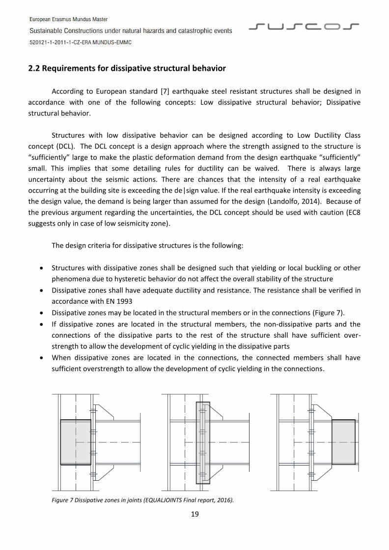
The design criteria for dissipative structures is the following:
Structures with dissipative zones shall be designed such that yielding or local buckling or other
phenomena due to hysteretic behavior do not affect the overall stability of the structure
Dissipative zones shall have adequate ductility and resistance. The resistance shall be verified in
accordance with EN 1993
Dissipative zones may be located in the structural members or in the connections (Figure 7).
If dissipative zones are located in the structural members, the non‐dissipative parts and the
connections of the dissipative parts to the rest of the structure shall have sufficient over-
strength to allow the development of cyclic yielding in the dissipative parts
When dissipative zones are located in the connections, the connected members shall have
sufficient overstrength to allow the development of cyclic yielding in the connections.
Figure 7 Dissipative zones in joints (EQUALJOINTS Final report, 2016).

20
2.3 Design of connections
The connections of structures under lateral forces induced by earthquakes shall be designed
according the following design rules [9].
(1) The design of connections shall be such as to limit localization of plastic strains, high residual
stresses and prevent fabrication defects.
(2) Non dissipative connections of dissipative members made by means of full penetration butt
welds may be deemed to satisfy the overstrength criterion.
(3) For fillet weld or bolted non dissipative connections, the following expression should be satisfied:
Rd ≥ 1,1 γov Rfy (6.1)
where: Rd is the resistance of the connection in accordance with EN 1993.
Rfy is the plastic resistance of the connected dissipative member based on the design
yield stress of the material as defined in EN 1993.
γov is the overstrength factor.
NOTE: The value ascribed to γov for use in a Country to check condition a) may be found in its
National Annex. The recommended value is γov = 1,25
(4) Categories B and C of bolted joints in shear in accordance with EN 1993-1-8:2004, 3.4.1 and
category E of bolted joints in tension in accordance with EN 1993-1-8:2004, 3.4.2 should be
used. Shear joints with fitted bolts are also allowed. Friction surfaces should belong to class A or
B as defined in ENV 1090-1.
(5) For bolted shear connections, the design shear resistance of the bolts should be higher than 1,2
times the design bearing resistance.
(6) The adequacy of design should be supported by experimental evidence whereby strength and
ductility of members and their connections under cyclic loading should be supported by
experimental evidence, in order to conform to the specific requirements defined in 6.6 to 6.9 for
each structural type and structural ductility class. This applies to partial and full strength
connections in or adjacent to dissipative zones.
(7) Experimental evidence may be based on existing data. Otherwise, tests should be performed.
NOTE: The National Annex may provide reference to complementary rules on acceptable
connection design.

21
2.4 Detailing of connections
(1) If the structure is designed to dissipate energy in the beams, the connections of the beams to the
columns should be designed for the required degree of overstrength (see 6.5.5) taking into
account the moment of resistance Mpl,Rd and the shear force (VEd,G + VEd,M) evaluated in 6.6.2.
(2) Dissipative semi-rigid and/or partial strength connections are permitted, provided that all of the
following requirements are verified:
a) The connections have a rotation capacity consistent with the global deformations;
b) Members framing into the connections are demonstrated to be stable at the ultimate limit
state (ULS);
c) The effect of connection deformation on global drift is taken into account using nonlinear
static (pushover) global analysis or non-linear time history analysis.
(3) The connection design should be such that the rotation capacity of the plastic hinge region θp
(Figure 8): is not less than 35 mrad for structures of ductility class DCH and 25 mrad for
structures of ductility class DCM with q > 2. The rotation θp is defined as θp = δ / 0,5L (6.10)
Where δ is the beam deflection at midspan
L is the beam span
The rotation capacity of the plastic hinge region θp should be ensured under cyclic loading without degradation of strength and stiffness greater than 20%. This requirement is valid independently of the intended location of the dissipative zones [9].
Figure 8 Plastic hinge region (EN 1998-1:2004)
(4) In experiments made to assess θp the column web panel shear resistance should conform to
expression (6.8) and the column web panel shear deformation should not contribute for more
than 30% of the plastic rotation capability θp.
(5) The column elastic deformation should not be included in the evaluation of θp.
(6) When partial strength connections are used, the column capacity design should be derived from
the plastic capacity of the connections.

22
2.4 Classification of connections
Joints are mainly classified by two parameters: By their stiffness and by their strength. The
classification of joint is under regulation of EN 1993-1-8:2005 [10].
2.4.1 Classification by stiffness
A joint may be classified as rigid, nominally pinned or semi-rigid according to its rotational
stiffness, by comparing its initial rotational stiffness Sj,ini with the classification boundaries (Figure 9).
Rules for the determination of Sj,ini for joints connecting H or I sections are given in 6.3.1. A joint may be
classified on the basis of experimental evidence, experience of previous satisfactory performance in
similar cases or by calculations based on test evidence.
Figure 9 Classification of joints by their stiffness (EN 1993-1-8:2005)
Nominally pinned joints
(1) A nominally pinned joint should be capable of transmitting the internal forces, without
developing significant moments which might adversely affect the members or the structure as a
whole.
(2) A nominally pinned joint should be capable of accepting the resulting rotations under the
design loads.
Rigid joints
(1) Joints classified as rigid may be assumed to have sufficient rotational stiffness to justify
analysis based on full continuity.
Semi-rigid joints
(1) A joint which does not meet the criteria for a rigid joint or a nominally pinned joint should be
classified as a semi-rigid joint. Semi-rigid joints provide a predictable degree of interaction
between members, based on the design moment-rotation characteristics of the joints.
(2) Semi-rigid joints should be capable of transmitting the internal forces and moments.

23
2.4.1 Classification by stiffness
A joint may be classified as full-strength, nominally pinned or partial strength by comparing its
design moment resistance Mj,Rd with the design moment resistances of the members that it connects.
When classifying joints, the design resistance of a member should be taken as that member adjacent to
the joint [10].
Nominally pinned joints
(1) A nominally pinned joint should be capable of transmitting the internal forces, without
developing significant moments which might adversely affect the members or the structure as a
whole.
(2) A nominally pinned joint should be capable of accepting the resulting rotations under the
design loads.
(3) A joint may be classified as nominally pinned if its design moment resistance Mj,Rd is not
greater than 0,25 times the design moment resistance required for a full-strength joint, provided
that it also has sufficient rotation capacity.
Full-strength joints
(1) The design resistance of a full strength joint should be not less than that of the connected
members.
(2) A joint may be classified as full-strength if it meets the criteria given in Figure 10.
Figure 10 Classification of joints by their stiffness (EN 1993-1-8:2005)
Partial-strength joints
(1) A joint which does not meet the criteria for a full-strength joint or a nominally pinned joint
should be classified as a partial-strength joint.

24
2.5 Research on prequalified connections EQUALJOINTS Project
Nowadays, prequalification criteria for steel beam-to-column joints in seismic resistant systems
are currently missing in Europe. Even though several experimental and analytical studies are available,
none was specifically addressed to select and prequalify European seismic-resistant joints on the basis
of parametric experimental and numerical investigations. At the current stage, EN 1998-1 allows using
dissipative beam-to-column connection, but it prescribes design supported by experimental testing,
which results in impractical solutions within the time and budget constraints of real-life projects. On the
other hand, no design tools to reliable predict the plastic rotation capacity of non-dissipative (namely
full strength) joints are available. Indeed, owing to the variability of steel strength, these connections
could not have enough overstrength, and in such cases their plastic rotation capacity must be
prequalified by relevant test and numerically based procedures.
In contrast to current European design methodology, the approach used in other countries with
high seismic hazard (e.g. USA and Japan) is based on codified and easy-to-use design tools and
procedures and prequalified seismic resistant joints are common practice. Unfortunately, joint
typologies and shape and properties of members, bolts and welds commonly used in US and Japanese
practices, are different from those typically used in Europe. Moreover, it should be noted that the
European seismic input differs from US earthquake, also affecting the ductility demand at both global
and local level and thus furtherly limiting the application of US prequalification to the European
practice.
In the light of these considerations, “Equaljoints” project was aimed at providing European
qualification of beam-to-column joints for seismic application, focusing on the standardization of design
and manufacturing procedures with reference to a set of selected joint configurations (Figure 11),
namely bolted haunched joints, bolted extended stiffened end-plate joint, bolted extended unstiffened
end-plate joint and welded dog-bone joint, which were designed to provide different performance
levels [11].
Figure 11 EQUALJOINTS prequalified beam-to-column joints: a) Bolted extended unstiffened endplate joint. b) Bolted
extended stiffened endplate joint. c) Bolted haunched joint. d) Welded dog-bone joint (EQUALJOINTS Final report, 2016).

25
The research activity developed within Equaljoint project was characterized as pre-normative
research intended to develop design tools and prequalification charts to be included in the next version
of EN 1998-1.
In order to meet the main objective a comprehensive experimental campaign (including 76
beam-to-column joint specimens) was successfully accomplished, as well as experimental tests devoted
to cyclic characterization both European mild carbon steel and high strength bolts. Moreover, a new
loading protocol for European prequalification, representative of European seismic demand was
developed [11].
Analytical and numerical models for predicting the behavior of beam-to-column joints under
cyclic loading were developed and validated on the basis of the experimental campaign. Parametric
numerical analyses were performed to investigate further cases not covered within experimental
program. Technological requirements for fabrication of standardized steel joints were defined.
The action plan is summarized in the following flowchart (Figure 12).
Figure 12 EQUALJOINTS Project research plan (EQUALJOINTS Final report, 2016).

26
2.2 Component method
The component method, as expressed in EC3 Annex J, allows evaluating by means of a unified
procedure, the stiffness and resistance properties of various bolted and welded steel connections. A
joint is generally considered as a whole and it is studied accordingly; the originality of the component
method when it was published is that it considers any joint as a set of individual basic components. For
example, in the case of a joint with extended end plate connection subject to bending (Figure 13), the
relevant components are the following:
Compression zone:
o Column web in compression
o Beam flange in compression
Tension zone:
o Column web in tension
o Column flange in bending
o Bolts in tension
o Endplate in bending
o Beam web in tension
Shear zone:
o Column web panel in shear
Figure 13 Component method application example (Jaspart, 2004).
Each of these basic components possesses its own level of strength and stiffness in tension,
compression or shear. The coexistence of several component to compression (or tension) and shear –
can obviously lead to stress interactions that are likely to decrease the strength and the stiffness of each
individual basic component; this interaction affects the shape of the deformability curve of the related
components but does not call the principles of the component method in question again [12].
The application of the component method requires the following steps:
a) Identification of the active components for the studied joint.
b) Evaluation of the stiffness and/or strength characteristics of each individual basic component
(specific characteristics – initial stiffness, design strength … - or whole deformability curve).
c) Assembling of the components in view of the evaluation of the stiffness and/or strength
characteristics of the whole joint (Figure 14) (specific characteristics – initial stiffness, design
strength, … - or whole deformability curve). The assembling is based on an assumed distribution
of the internal forces within the joint.

27
Figure 14 Illustration of assembling components (Steel Connections Design Course, SUSCOS 2016).
The application of the component method requires a sufficient knowledge of the bahaviour of
the basic components, which are given in EC3 Annex J. The combination of these components allows to
cover a wide range of joint configurations, what should largely be sufficient to satisfy the need of
practitioners as far as beam-to-column joints and beam splices in bengin are concerned.
The framework of the component method is sufficiently general to allow the use of various
techniques of component characterization and joint assembling. In particular, the stiffness and strength
characteristics of the components may result from experimentations in laboratory, numerical
simulations by means of finite element programs or analytical models based on theory, as in Annex J.

28
2.3 Component based finite element method
Finite element models (FEM) for connections are used from 70s of last century and they are
research-oriented. Their ability to express real behavior of connections is making them a valid
alternative to testing - standard and expensive source of knowledge of connection’s behavior [13].
Native process of computer based design is validation and verification (VaV) of models [14]. Application
of VaV to steel connections design is limited to a few published benchmark studies [15]. Comparison of
VaV to different engineering application is still to be done [16].
Component based finite element model (CBFEM) is based on decomposition of the whole joint
into separated components - steel plates, welds, bolts, anchors and concrete block. Each component
has its own analysis model [17]:
2D plate/wall finite elements for steel plates of stubs of hot/cold formed cross section;
force interpolation constrains for welds;
nonlinear springs for bolts and anchors;
contact elements between plates in connections;
Winkler/Pasternak subsoil for concrete blocks.
First step in creating of the model is preparation of its geometry. Structural engineer creates the
structural joint by applying manufacturing operations using these components (Figure 15). Meshing of
the components is automatically done by software.
Figure 15 Predefined components in CBFEM (Wald, F. et al, 2015).

29
The plates connected by welds are modeled separately. They are connected by weld component
only, which is characterized by weld in plane and out of plane tensile stiffness and resistance. The bolts
are modeled as two fans of interpolation links with its tensile and shear trilinear stiffness and adequate
resistance. Slender compressed plates are checked for local buckling. Possible post buckling behavior of
thin-walled sections is introduced by effective stress of each compressed plate.
2.3.1 Material model
The most common material diagrams, which are used in finite element modelling of structural
steel, are the ideal plastic or elastic model with strain hardening and the true stress-strain diagram
(Figure 16). The true stress-strain diagram is calculated from the material properties of mild steels at
ambient temperature obtained in tensile tests. The true stress and strain may be obtained as follows:
σtrue = σ (1 + ε)
εtrue = ln(1 + ε)
where σtrue is true stress, εtrue true strain, σ nominal stress and ε nominal strain. The elastoplastic
material with strain hardening is modelled according to EN1993-1-5:2005 [18].
The material behaviour is based on Von Mises yield criterion. It is assumed to be elastic before
reaching the yield strength fy. The ultimate limit state criterion for regions not susceptible to buckling is
reaching of a limiting value of the principal membrane strain. The value of 5 % is recommended.
Figure 16 Material diagrams of steel in numerical models (Wald, F. et al, 2014).

30
2.3.2 Plate model and mesh convergence
Plate model
Shell elements are recommended for modelling of plates in design FEA of structural connection.
4-node quadrangle shell elements with nodes at its corners are applied. Six degrees of freedom are
considered in every node: 3 translations (ux, uy, uz) and 3 rotations (φx, φy, φz). Deformations of the
element are divided into membrane and flexural components.
The formulation of the membrane behaviour is based on the work by Ibrahimbegovic (1990).
Rotations perpendicular to the plane of the element are considered. Complete 3D formulation of the
element is provided. The out-of-plane shear deformations are considered in the formulation of the
flexural behaviour of element based on Mindlin hypothesis. The MITC4 elements are applied, see
Dvorkin (1984). The shell is divided into five integration points along the height of the plate and plastic
behaviour is analysed in each point. It is called Gaus - Lobatto integration. The nonlinear elastic-plastic
stage of material is analysed in each layer based on the known strains.
Mesh convergence
There are some criteria of the mesh generation in the connection model. The connection check
should be independent on the element size. Mesh generation on a separate plate is problem-free. The
attention should be paid to complex geometries such as stiffened panels, T-stubs and base plates. The
sensitivity analysis considering mesh discretisation should be performed for complicated geometries.
All plates of a profile have common size of elements. Size of generated finite elements is limited.
Minimal element size is set to 10 mm and maximal element size to 50 mm. Meshes on flanges and webs
are independent on each other. Default number of finite elements is set to 8 elements per cross-section
height (Figure 17a). The mesh of end plates is separate and independent on other connection parts.
Default finite element size is set to 16 elements per cross-section height (Figure 17b).
a) Mesh on beam with constrains between web and flange. b) Mesh on end plate, with 7 elements on width. Figure 17 Plate mesh on profiles and endplate (Wald, F. et al, 2014).

31
2.3.3 Welds
There exist several options how to treat welds in numerical models. Large deformations make
the mechanical analysis more complex and it is possible to use different mesh descriptions, different
kinetic and kinematic variables, and constitutive models. The different types of geometric 2D and 3D
models and thereby finite elements with their applicability for different accuracy levels are generally
used. Most often used material model is the common rate-independent plasticity model based on von
Mises yield criterion. Two approaches which are used for welds are described.
Direct connection of plates
The first option of weld model between plates is direct merge of meshes (Figure 18a). The load is
transmitted through a force-deformation constrains based on Lagrangian formulation to opposite plate.
The connection is called multi point constraint (MPC) and relates the finite element nodes of one plate
edge to another. The finite element nodes are not connected directly. The advantage of this approach is
the ability to connect meshes with different densities. The constraint allows to model midline surface of
the connected plates with the offset, which respects the real weld configuration and throat thickness.
The load distribution in weld is derived from the MPC, so the stresses are calculated in the throat
section. This is important for the stress distribution in plate under the weld and for modelling of T-stubs.
This model does not respect the stiffness of the weld and the stress distribution is conservative.
Stress peaks, which appear at the end of plate edges, in corners and rounding, govern the resistance
along the whole length of the weld. To eliminate the effect three methods for evaluation of the weld
can be chosen maximal stress (conservative)
Average stress on weld
Linear interpolation along weld
Plastic weld
To express the weld behavior an improved weld model is applied. A special elastoplastic element
is added between the plates. The element respects the weld throat thickness, position and orientation.
The equivalent weld solid is inserted with the corresponding weld dimensions (Figure 18b). The
nonlinear material analysis is applied and elastoplastic behavior in equivalent weld solid is determinate.
Ideal plastic model is used and the plasticity state is controlled by stresses in the weld throat section.
The plastic strain in weld is limited to 5% as in the plate. The stress peaks are redistributed along the
longer part of the weld length.

32
a) Constraint between mesh nodes b) Constraint between weld element and mesh nodes
Figure 18 Weld idealization in CBFEM (Wald, F. et al, 2014).
2.3.4 Bolts
In the CBFEM is component bolt with its behavior in tension, shear and bearing by the
dependent nonlinear springs. The bolt in tension is described by spring with its axial initial stiffness,
design resistance, initialisation of yielding and deformation capacity. The axial initial stiffness is derived
analytically in guideline VDI2230. The model corresponds to experimental data; see (Gödrich et al 2014).
For initialization of yielding and deformation capacity is assumed that plastic deformation occurs in the
threated part of the bolt shank only. The force at beginning of yielding Fy,ini is Fy,ini = fy,b At (3.4.1) where,
fy,b is yield strength of bolts and At tensile area of the bolt. Relation (3.4.1) gives for materials with low
ratio of the ultimate strength to yield strength higher values than design resistance Ft,Rd. To assure a
positive value of plastic stiffness it should be taken 𝐹𝑦,𝑖𝑛𝑖 ≤ 𝐹𝑡,𝑅𝑑(3.4.2)
Deformation capacity of the bolt c consists of elastic deformation of bolt shank el and plastic
one of the threated part only pl. 𝛿𝑐 = 𝛿𝑒𝑙 + 𝛿𝑝𝑙 (3.4.3), 𝛿𝑒𝑙 =𝐹𝑡,𝑅𝑑
𝑘𝑖𝑛𝑖 (3.4.4), where kini is initial
deformation stiffness of the bolt in tension according to guideline VDI2230, and 𝛿𝑝𝑙 = 휀𝑝𝑙 𝑙𝑡 (3.4.5)
where, εpl is limiting plastic strain, given by value 5 %, and lt is length of threated part. The tensile force
is transmitted to the plates by interpolation links between the bolt shank and nodes in the plate. The
transfer area corresponds to the mean value of the bolt shank and the circle inscribed in the hexagon of
the bolt head.
The initial stiffness and design resistance of bolts in shear is in CBFEM modelled according to in
cl. 3.6 and 6.3.2 in EN1993-1-8:2006. Linear behavior up to failure is considered. The spring representing
bearing (Figure 19) has bi-linear force deformation behavior with initial stiffness and design resistance
according to in cl. 3.6 and 6.3.2 in EN1993-1-8:2006. Deformation capacity is considered according to
(Wald et al 2002) as 𝛿𝑝𝑙 = 3 휀𝑒𝑙 (3.4.6). Initialization of yielding is expected at Fini = 2/3 Fb,Rd (3.4.7).
Equivalent load
Multi point constraint
τ σ
Weld throat section
Equivalent solid Weld element
Equivalent
load
Multipoint constraint

33
Figure 19 Force deformation diagram for bearing of the plate (Wald, F. et al, 2014).
Interaction of axial and shear force in the bolt is considered according to Tab. 3.4 in EN1993-1-
8:2006. Only the compression force is transferred from the bolt shank to the plate in the bolt hole. It is
modelled by interpolation links between the shank nodes and holes edge nodes. The deformation
stiffness of the shell element, which models the plates, distributes the forces between the bolts and
simulates the adequate bearing of the plate.
F
Relative deformation, δ
δel δpl
Fb,Rd
2/3 Fb,Rd
k
ks

34
3. MOMENT CONNECTIONS FOR SEISMIC AREAS
Three different types of connections have been considered within this study (Figure 20). These
connections were previously designed by the EQUAJOINTS project by performing structural analyses of
typical building configurations used frequently in European countries by considering current state-of-
practice in Europe.
Figure 20 Studied joints configurations (Vulcu, C. et al, 2016).
3.1 Specimens
The main core of the experimental activity carried out within the project is dealing with the tests
performed on joint specimens: three bolted beam to column joint typologies were investigated within
the project (namely (a) haunched bolted joints, (b) unstiffened extended endplate bolted joints and (c)
stiffened extended endplate bolted joints, and dog-bone welded joints (d) designed to meet different
performance levels. The experimental program (Table 1) included 76 beam-to-column specimens by
varying the joint typologies, the performance objectives, the joint configuration (internal/external
joints), and the loading protocol (monotonic and 2 different cyclic loading protocols) [11].
Parameter Variation
Beam to column assembly Small beam (IPE360) - Medium beam (IPE450) - Deep beam (IPE60)
Joint type Haunched - Extended stiffened endplate - Extended unstiffened endplate - Dogbone
Joint configuration Internal/External
Performance objective Full strength - Equal strength - Partial strength
Loading protocol Monotonic - Cyclic AISC - Cyclic Proposed EU Table 1 Experimental program EQUALJOINTS Project
35
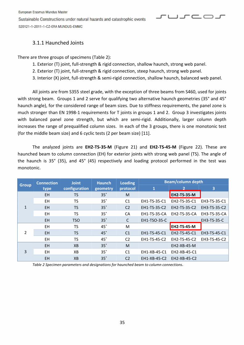
3.1.1 Haunched Joints
There are three groups of specimens (Table 2):
1. Exterior (T) joint, full-strength & rigid connection, shallow haunch, strong web panel.
2. Exterior (T) joint, full-strength & rigid connection, steep haunch, strong web panel.
3. Interior (X) joint, full-strength & semi-rigid connection, shallow haunch, balanced web panel.
All joints are from S355 steel grade, with the exception of three beams from S460, used for joints
with strong beam. Groups 1 and 2 serve for qualifying two alternative haunch geometries (35° and 45°
haunch angle), for the considered range of beam sizes. Due to stiffness requirements, the panel zone is
much stronger than EN 1998-1 requirements for T joints in groups 1 and 2. Group 3 investigates joints
with balanced panel zone strength, but which are semi-rigid. Additionally, larger column depth
increases the range of prequalified column sizes. In each of the 3 groups, there is one monotonic test
(for the middle beam size) and 6 cyclic tests (2 per beam size) [11].
The analyzed joints are EH2-TS-35-M (Figure 21) and EH2-TS-45-M (Figure 22). These are
haunched beam to column connection (EH) for exterior joints with strong web panel (TS). The angle of
the haunch is 35° (35), and 45° (45) respectively and loading protocol performed in the test was
monotonic.
Group Connection type
Joint configuration
Haunch geometry
Loading protocol
Beam/column depth
1 2 3
1
EH TS 35˚ M EH2-TS-35-M
EH TS 35˚ C1 EH1-TS-35-C1 EH2-TS-35-C1 EH3-TS-35-C1
EH TS 35˚ C2 EH1-TS-35-C2 EH2-TS-35-C2 EH3-TS-35-C2
EH TS 35˚ CA EH1-TS-35-CA EH2-TS-35-CA EH3-TS-35-CA
EH TSO 35˚ C EH1-TSO-35-C EH3-TS-35-C
2
EH TS 45˚ M EH2-TS-45-M
EH TS 45˚ C1 EH1-TS-45-C1 EH2-TS-45-C1 EH3-TS-45-C1
EH TS 45˚ C2 EH1-TS-45-C2 EH2-TS-45-C2 EH3-TS-45-C2
3
EH XB 35˚ M EH2-XB-45-M
EH XB 35˚ C1 EH1-XB-45-C1 EH2-XB-45-C1
EH XB 35˚ C2 EH1-XB-45-C2 EH2-XB-45-C2
Table 2 Specimen parameters and designations for haunched beam to column connections.

36
EH2-TS-35-M
Figure 21 Detail drawing for joint EH2-TS-35-M (Annex I to D-WP1-4, UPT 2015).

37
EH2-TS-45-M
Figure 22 Detail drawing for joint EH2-TS-45-M (Annex I to D-WP1-4, UPT 2015).

38
3.1.2 Stiffened extended end-plate joint
Stiffened endplate connections cover three groups of specimens (Table 3):
1. Exterior (TS) joint, full-strength connection with strong web panel
2. Exterior (TS) joint, equal strength connection with strong web panel
3. Interior (XB) joint, equal strength connection with balanced web panel
All specimens are made of S355 steel grade. Groups 1 and 2 serve for qualifying joints according
to two alternative performance criteria applied to stiffened extended end plate connections (full-
strength and equal-strength) for the considered range of beam sizes; the column web panel is designed
to be over-strong respect to the connection zone in both cases. Group 3 investigates internal joints with
balanced column web panel (XB).
There are 6 cyclic tests (2 per beam size) in each group. There are 6 cyclic tests (2 per beam size)
in each group. In the first group there are 2 more monotonic tests in order to clearly evaluate the
influence of the beam-to-column ratio. Also, there is one cyclic test with the alternative load protocol.
Additionally, in Group 2 (TS configuration equal-strength connections) there are three cyclic tests (one
for each beam size) for specimens with shot-peening applied to welds [11].
The analyzed joints are ES1-TS-F-M (Figure 23) and ES3-TS-F-M (Figure 24). These are extended
stiffened endplate beam to column connection (ES) for exterior joints with strong web panel (TS). They
are full-strength connection (F) and the loading protocol performed in the test was monotonic.
Group Connection type
Joint configuration
Connection strength
Loading protocol
Beam/column depth
1 2 3
1
ES TS F M ES1-TS-F-M ES3-TS-F-M
ES TS F C1 ES1-TS-F-C1 ES2-TS-F-C1 ES3-TS-F-C1
ES TS F C2 ES1-TS-F-C2 ES2-TS-F-C2 ES3-TS-F-C2
ES2-TS-F-CA
2
ES TS E C1 ES1-TS-E-C1 ES2-TS-E-C1 ES3-TS-E-C1
ES TS E C2 ES1-TS-E-C2 ES2-TS-E-C2 ES3-TS-E-C2
ES TS Esp C ES1-TS-Esp-C ES2-TS-E-C ES3-TS-Esp-C
3 ES XB E C1 ES1-XB-E-C1 ES2-XB-E-C1 ES3-XB-E-C1
ES XB E C2 ES1-XB-E-C2 ES2-XB-E-C2 ES3-XB-E-C2 Table 3 Specimen parameters and designations for stiffened end-plate beam to column connections.

39
ES1-TS-F-M
Figure 23 Detail drawing for joint ES1-TS-F-M (Annex I to D-WP1-4, UPT 2015).
ES3-TS-F-M
Figure 24 Detail drawing for joint ES3-TS-F-M (Annex I to D-WP1-4, UPT 2015).
HEB280
IPE360
M30
HEB500
IPE600
M36

40
3.1.3 Unstiffened extended end-plate joint
Unstiffened endplate connections designed by ULg cover three groups of specimens, as follows:
1. Exterior (TB) joint, equal strength connection with balanced web panel.
2. Exterior (TB) joint, 0.6 partial strength connection with balanced web panel.
3. Interior (XW) joint, 0.8 partial strength connection with weak web panel.
All joints are made of S355 steel grade. Groups 1 and 2 serve for qualifying joints according two
alternative performance criteria applied to unstiffened extended end plate connections (equal-strength
and 0.6 partial-strength) for the considered range of beam sizes; the column web panel is designed to
be balanced respect to the connection zone in both cases. Group 3 investigates internal (XW) joints
with weak column web panel [11].
There are 6 cyclic tests (2 per beam size) in each group. In the first group there are 2 more
monotonic tests in order to clearly evaluate the influence of the beam-to-column ratio. Also, there is
one cyclic test with the alternative load protocol.
The analyzed joints are E1-TB-E-M (Figure 25) and E2-TB-E-M (Figure 26). This is an unstiffened
endplate beam to column connection (E) for exterior joint with balanced web panel (TB). It is an equal-
strength connection (E) and the loading protocol performed in the test was monotonic.
Group Connection type
Joint configuration
Connection strength
Loading protocol
Beam/column depth
1 2 3
1
E TB E M ES1-TS-F-M ES2-TS-F-M
E TB E C1 ES1-TS-F-C1 ES2-TS-F-C1 ES3-TS-F-C1
E TB E C2 ES1-TS-F-C2 ES2-TS-F-C2 ES3-TS-F-C2
E TB E CA ES3-TS-F-CA
2
E TB P C1 ES1-TS-E-C1 ES2-TS-E-C1 ES3-TS-E-C1
E TB P C2 ES1-TS-E-C2 ES2-TS-E-C2 ES3-TS-E-C2
E TB Psp C ES1-TS-Esp-C ES2-TS-E-C ES3-TS-Esp-C
3 E XW P C1 ES1-XB-E-C1 ES2-XB-E-C1 ES3-XB-E-C1
E XW P C2 ES1-XB-E-C2 ES2-XB-E-C2 ES3-XB-E-C2 Table 4 Specimen parameters and designations for unstiffened end-plate beam to column connections.

41
E1-TB-E-M
Figure 25 Detail drawing for joint E1-TB-E-M (Annex I to D-WP1-4, UPT).
E2-TB-E-M
Figure 26 Detail drawing for joint E2-TB-E-M (Annex I to D-WP1-4, UPT).
M30
M27

42
3.2 Test results
The following information forms part of the EQUALJOINTS Project conformed by the consortium
of universities: Università degli Studi di Napoli Federico II, Universite de Liege, Universitatea Politehnica
din Timisoara, Imperial College of Science, Technology and Medicine, Universidade de Coimbra and the
steel sector partners European Convention for Constructional Steelwork Vereniging and Arcelormittal
Belval & Differdange SA. The results of the tests performed within the project have been replicated and
summarized here for a better understanding of this study.
Performance
The performance parameters of joints were obtained from both the envelopes of the cyclic and
the monotonic response curves given by the moment at column face vs the chord rotation (i.e. Mcf-ϴ).
The initial stiffness (Kini) was obtained by a linear fit of points on the envelope corresponding to values of
the bending moment below 0.7 times the maximum one (Mmax). The yield bending moment (My) was
determined at the intersection of the initial and tangent stiffness lines. The latter is defined by a linear
fit of data points on the Mcf-ϴ curve located between 0.8Mmax and Mmax. Lastly, ultimate deformation ϴu is
determined as point on the Mcf-ϴ envelope corresponding to a drop of moment of 0.8 times the
maximum one. For initial stiffness, yield moment and maximum moment the average of the positive
and negative values are reported, while the minimum value for ultimate chord rotation. The obtained
parameters are reported in Table 4. Additionally the strain hardening coefficient (γh) is computed as the
ratio between the maximum and yield moments, as well as the plastic ultimate drift ϴpl,u, defined as the
total ultimate drift minus the elastic drift obtained using the initial stiffness [11].
Typology of connection Performance parameters
Kini (kNm/rad) My (kNm) Mmax (kNm) γh ϴu (rad) ϴpl,u (rad)
Haunched joint
EH2-TS35-M 65636.8 792.6 931.7 1.18 0.118 0.107
EH2-TS45-M 69514.3 798.6 957.2 1.20 0.124 0.113
Extended stiffened joint
ES1-TS-F-M 22449.0 436.2 577.5 1.32 0.100 0.080
ES3-TS-F-M 198040.1 1706.4 2181.5 1.28 0.071 0.062
Extended unstiffened joint
E1-TB-E-M 16666.7 308.9 423.1 1.37 0.107 0.089
E2-TB-E-M 42424.2 558.0 755.3 1.35 0.068 0.055 Table 5 Performance of tested beam-to-column joints in EQUALJOINTS Project.
Failure mechanism
The experimental results on haunched joints confirm that plastic deformations are concentrated
in the portion of the beam adjacent to the haunch, while deformations in the column panel zone and
connection are negligible. The failure of these joints occurs either into the beam flange of the plastic
hinge due to low-cycle fatigue cracking, or in the heat-affected zone (HAZ) of the weld between haunch
and beam flanges, or at the interface between beam web and flange.

43
The failure modes of extended stiffened joints depend on the design performance level. Indeed,
those designed as full strength joints exhibit a failure mode similar to haunched joints (i.e. plastic hinge
of the beam with progressive deterioration due to local buckling and fracture of the beam due to low
cycle fatigue) (Figure 27). On the contrary, the joints designed as equal strength with full strength web
panel show a more complex failure mechanism with the plastic deformations in both beam (i.e. local
buckling of the flanges) and connection (i.e. end-plate in bending) (Figure28).
Figure 27 Failure mode on full-strength connection. Figure 28 Failure mode on equal-strength connection.
Pictures by the Università degli Studi di Napoli Federico II, 2015.
The failure modes of extended unstiffened joints are mostly characterized by plastic deformation
of the connection (i.e. end-plate in bending) and column web panel. Hence, these types of joints
substantially differ from both haunched and extended stiffened assemblies. The failure mostly occurs
for the excessive concentration of plastic strain close to welds between the beam flange and the end-
plate, which generally occurs on beam side for equal strength connections (Figure 29) and into the end-
plate for partial strength connections (Figure 30). However, all tests show that the contribution of
column web panel is significantly high with large plastic deformations [11].
Figure 29 Failure mode on equal-strength connection. Figure 30 Failure mode on partial-strength connection.
Pictures by the Università degli Studi di Napoli Federico II, 2015.

44
4. OBJECTIVES
Develop 3D shell element models with the use of software IDEAStatiCa by replicating the
parameters employed in the experimental program of Equaljoints project.
Propose a set of accurate input details to obtain reliable numerical models in conformation to
experimental and analytical models.
Validation of numerical models by comparing outputs of numerical models to experimental
results from the Equaljoints project.
Develop 2D models with the use of software FIN EC Steel Connections by replicating the
parameters employed in the 3D shell element models.
Verification of numerical models by comparing outputs of numerical models to analytical results
from FIN EC Steel Connections
Perform sensitivity tests on numerical models by changing properties of the connection
components in order to understand better the strength behavior and failure modes of the
studied joint.
Investigate CBFEM accuracy of results in order to propose further developments to a state-of-
the-are designing tool.

45
5. NUMERICAL MODELS OF JOINTS
This Chapter is divided mainly in 2 parts; the first part involves the validations with test results of
the Equaljoints project and the second part contains the verification of the CBFEM models by comparing
CM models.
5.1 Validation of CBFEM models
5.1.1 Calibration
Material
The calibration of the material properties was performed in accordance to the results of the
tensile test performed by UPT. The test was performed to the flanges and webs of the profiles. From
the tensile test, the average yield stress and ultimate strength values for column, beam and endplate
are obtained and compared to those from the standard [19].summarized (Table 6).
Profile
EN 10025-2,3:2004 Tensile tests
Reh (N/mm2)
Rm (N/mm2)
Reh (N/mm2)
Rm (N/mm2)
γov
HEB S355 355 470-630 410 510 1.15
IPE S355 355 470-630 425 515 1.20
Plates S355 355 470-630 400 500 1.13 Table 6 Tensile test results in EQUALJOINTS Project.
Partial safety factors
The software used to obtain the actual strength of the joint is a design oriented program
therefore all partial safety factors recommended by standards [10], [20] have been modified to unity
(Table 7)
Partial safety factors for joints
Resistance of members γM1=1
Resistances of cross sections γM2=1
Resistance of bolts
γM3=1 Resistance of welds
Resistance of plates in bearing
Slip resistance γM7=1 Table 7 Partial safety factors for joints

46
5.1.2 Numerical Simulation
In total 6 component-based finite element (CBFE) models (Figure 31-33) were performed in
IdeaStatiCa [21]. As mentioned in chapter 2, in CBFE models all steel plates of stubs of hot/cold formed
cross section are modelled as shell finite elements, while welds are encoded as force interpolation
constrains and bolts as nonlinear springs. All welds are double fillet except the beam flange to endplate
weld which is butt weld and the weld for the double plate which is single fillet type. In all cases the
shear plane of bolts are in thread and they are bearing-tension shear interaction.
Figure 31 CBFE models of EH2- TS-35-M and EH2-TS-45-M in IdeaStatiCa.
Figure 32 CBFE models of ES1-TS-F-M and ES3-TS-F-M in IdeaStatiCa.

47
Figure 33 CBFE models of E1-TS-E-M and E2-TS-E-M in IdeaStatiCa.
5.1.3 Results
The CBFE models were subjected to the previous calibration and their results are summarized
(Table 8) and depicted (Figure 34) additionally the rotation capacities (Figure 35) were obtained and
compared to those observed on test.
Typology of connection
Performance parameters
Test CBFEM Test CBFEM
Mmax (kNm) Mmax (kNm) % ϴu (rad) ϴu (rad)
Haunched joint
EH2-TS35-M 2 931.7 889.1 5% 0.118 0.093
EH2-TS45-M 2 957.2 875.0 9% 0.124 0.092
Extended stiffened joint
ES1-TS-F-M 1 577.52 533.2 8% 0.100 0.066
ES3-TS-F-M 3 2181.53 1920.0 14% 0.071 0.056
Extended unstiffened joint
E1-TB-E-M 1 423.1 389.0 9% 0.107 0.057
E2-TB-E-M 2 755.32 681.0 11% 0.068 0.043 Table 8 Performance comparison between CBFEM and test.

48
Figure 34 Joint resistances comparison between CBFEM and test.
Figure 35 Deformation capacity comparison between CBFEM and test.
300
500
700
900
1100
1300
1500
1700
1900
2100
2300
0 1 2 3
Beam/column depth
Joint resistance
TEST
CBFEM
0.00 0.02 0.04 0.06 0.08 0.10 0.12 0.14
EH2-TS35-M
EH2-TS45-M
ES1-TS-F-M
ES3-TS-F-M
E1-TB-E-M
E2-TB-E-M
Deformation capacity
CBFEM
TEST
ES1-TS-F-M
EH2-TS35-M
E2-TB-E-M
EH2-TS35-M
EH2-TS45-M
ES3-TS-F-M
EH2-TS35-M
E1-TB-E-M

49
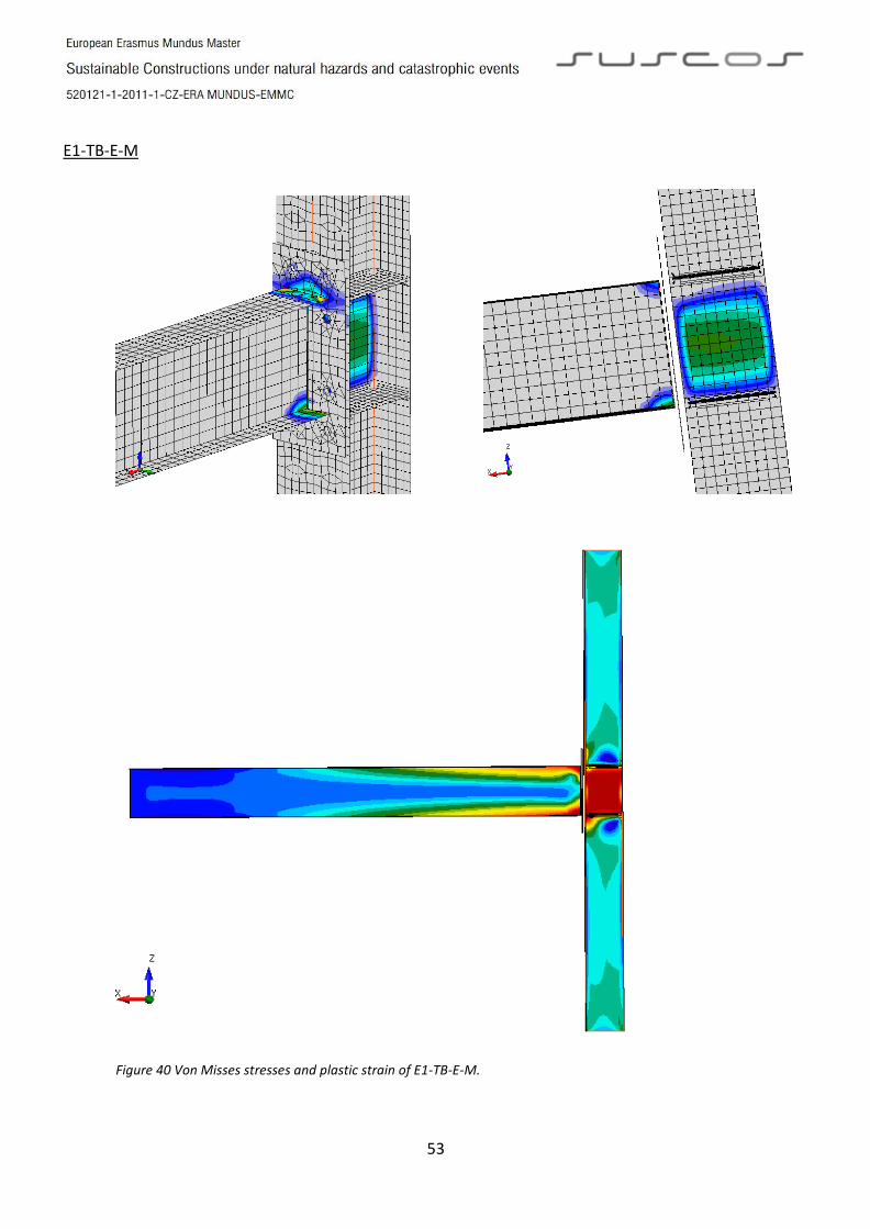
5.1.4 Failure mode
All CBFE models agree with the test failures modes described in chap. 4. For full strength joints,
the plastic hinge was developed in the beam just before the haunch and beam-to-end stiffener. For
equal strength joints, the plastic deformation is observed mainly in the column web panel and in the
endplate. For all cases the Von Misses stresses and plastic strain at the state of failure are shown.
EH2-TS-35-M
Figure 36 Von Misses stresses and plastic strain of EH2-TS-35-M.

50
EH2-TS-45-M
Figure 37 Von Misses Stresses and plastic strain of EH2-TS-45-M.

51
ES1-TS-F-M
Figure 38 Von Misses stresses and plastic strain of ES1-TS-F-M.

52
ES3-TS-F-M
Figure 39 Von Misses stresses and plastic strain of ES3-TS-F-M.
53
E1-TB-E-M
Figure 40 Von Misses stresses and plastic strain of E1-TB-E-M.

54
E2-TB-E-M
Figure 41 Von Misses Stresses and plastic strain of E2-TB-E-M.

55
5.2 Verification of CBFE models
CBFE models are verified with analytical solutions of CM (Figure 42-44) in order to perform
parametric study afterwards. The CM based software employed for verification is FIN EC- Steel
Connection, granted exclusively for this research by czech company FINE. FIN EC - Steel Connection [22]
is design oriented therefore the same calibration was done in order to obtain comparable results. The
joint capacities plus the decisive components (Table 9) were obtained and are depicted in figure 45.
EH2-TS-35-M EH2-TS-45-M
Figure 42 CM models of EH2- TS-35-M and EH2-TS-45-M in FIN EC-Steel Connections.
ES1-TS-F-M ES3-TS-F-M
Figure 43 CM models of ES1-TS-F-M and ES3-TS-F-M in FIN EC-Steel Connections.

56
E1-TB-E-M E2-TB-E-M
Figure 44 CM models of E1-TS-E-M and E2-TS-E-M in FIN EC-Steel Connections.
Typology of connection
CM CBFEM Decisive component
Mu (kNm) Mu (kNm) % row no.1 row no.2
Haunched joint
EH2-TS35-M 901.2 889.1 1% Endplate in bending Haunch flange in comp.
EH2-TS45-M 959.3 875.0 10% Endplate in bending Haunch flange in comp.
Extended stiffened joint
ES1-TS-F-M 547.5 533.2 3% Column flange in bend. Column wall in comp.
ES3-TS-F-M 1389 1920 -28% Column flange in bend. Column wall in comp.
Extended unstiffened joint
E1-TB-E-M 347.8 389.0 -11% Endplate in bending Column wall in shear
E2-TB-E-M 577 681.0 -15% Endplate in bending Column wall in shear Table 9 Performance comparison between CBFEM and CM.
Figure 45 Joint resistances comparison between CBFEM and CM.
Stiff end platecolumn-beam
HE 280 B - EN 10210-1 : S 355
P20.0 280.0x590.0 - EN 10210-1 : S 355
65
.0
12
2.0
2
16
.0
12
2.0
70.0
11
5.0
IPE 360 - EN 10210-1 : S 355
4.0 326.6
8.0 170.0
8 M27 - Bolt 10.9
P20.0 280.0x590.0 - EN 10210-1 : S 355
65
.0
12
2.0
2
16
.0
12
2.0
70.0
11
5.0
IPE 360 - EN 10210-1 : S 355
4.0 326.6
8.0 170.0
8 M27 - Bolt 10.9
300
500
700
900
1100
1300
1500
1700
1900
2100
2300
0 1 2 3
Beam/column depth
Joint resistance
CM
CBFEM
Stiff end platecolumn-beam
HE 340 B - EN 10210-1 : S 355
P25.0 300.0x700.0 - EN 10210-1 : S 355
70
.0
13
4.0
2
92
.0
13
4.0
75.0
12
5.0
IPE 450 - EN 10210-1 : S 355
8.0 410.8
10.0 190.0
8 M30 - Bolt 10.9
P25.0 300.0x700.0 - EN 10210-1 : S 355
70
.0
13
4.0
2
92
.0
13
4.0
75.0
12
5.0
IPE 450 - EN 10210-1 : S 355
8.0 410.8
10.0 190.0
8 M30 - Bolt 10.9

57
6. PARAMETRIC STUDY
In practice engineers regularly like to model structures with rigid and full-strength connections
and where typically the hinge region is located in the beam. The following parametric study using
CBFEM intends to achieve this for the unstiffened endplate connection E1-TB-E-M which is a semi-rigid
and equal-strength connection. In the previous analysis of the joint with CM, it can be seen that the
decisive components are: Endplate in bending and column wall in shear therefore in order to increase
the resistance of the connection, 3 options are considered.
Based on the model of E1-TB-E-M calibrated with the experimental result, which is the reference
model, parametric investigations are conducted. Primarily, the influence of the endplate thickness is
investigated. Secondly, the importance of supplementary web plates is studied because the experiment
was performed on only beam-to-column joint without the use of double plate. To conclude, the effect
of the application of different steel grades for beam and column is considered
This is a design purpose study therefore the nominal strength of steel S355 based on EN10025
[19], safety factors as well as design requirement by EN will be taking into account. In chapter 2, it was
presented how joints are classified, henceforward those rules are applied. In order for E1-TB-E-M to be
classified as a rigid connection, it shall have an initial stiffness Sj,ini ≥ kbEIb/Lb.
where: kb is a factor defined in section 5 by EN 1998-1-8 For IPE360 kb = 25
E is the design elastic modulus E = 210000N/mm2
Ib is the second moment of inertia. Ib = 162700000mm4
Lb is the beam length Lb = 6000mm
For all parametric studies the joint shall have an initial stiffness Sj,ini =142,4MNm/rad.
Furthermore, in order E1-TB-E-M to be considered as full-strength it must have a resistance
Mj,Rd≥ Mb,pl,Rd, where Mb,pl,Rd is the plastic bending resistance of the beam and can be calculated with the
expression Mb,pl,Rd=Wb,pl fy/γM0. According to EN 1998-1, fy shall be the actual maximum yield strength
fy,max=1,1 γov fy. For the case where the steel grade is different there is no need for γov which can be set
equal to 1.
where: Wb,pl is the plastic section modulus Wb,pl = 1019200mm3
fy is the yield strength fy = 355N/mm2
γM0 is the partial safety factor for steel γM0 = 1
γov is the material overstrength factor γov =1,25 for 6.1and6.2
γov = 1,00 for 6.3
Finally, the joint can be categorized as full-strength if it has a resistance Mj,Rd≥497,5kNm for
parametric study 6.1 and 6.2. For parametric study 6.3 the resistance shall be Mj,Rd≥398kNm. A second
bending resistance is computed Mj,Rd* which is the joint resistance without taking into account the
beam components (flange in compression and flange in tension) since these components limit the
resistance within the CBFE software.

58
6.1 Endplate thickness
The purpose of this investigation is to assess the influence of the endplate thickness which is a
critical component of extended unstiffened endplate joints. Three different endplate thicknesses are
considered based on commercial availability. E1-TB-E-25 and E1-TB-E-30 (Table 10) are modelled in the
same way as the reference model, E1-TB-E-M.
SPECIMEN …E-M …E-25 …E-30
Column HEB280 HEB280 HEB280
Beam IPE360 IPE360 IPE360
Endplate 20mm 25mm 30mm
Bolts M27 M27 M27
Sj,ini (MNm/rad) 67,5 77,0 86,0
Stiffness class Semi Semi Semi
Mj,Rd (kNm)
Mj,Rd*(kNm)
337,7
396,8
361,3
410,9
369,8
425,1
Strength class Partial Partial Partial
Table 10 Unstiffened endplate joints for parametric CBFEM investigation on endplate thickness.

59
Figure 46 Stiffness diagrams of E1-TB-E-M with parametric study endplate thickness.
Figure 47 Joint resistance of E1-TB-E-M with parametric study endplate thickness.
The joint resistance increases slowly by 4% while the initial stiffness increases by 14% with
thicker endplates (Table 10).
The deformation capacity decreases by 29% although it is still more than 40mrad (Figure 46).
The plastic strain plots (Figure 47) shows how the plastic strain in the endplate is fading while it
is initiating in the web panel. It can also be seen how a plastic hinge is formed in the web panel
before than in the beam.
It is not possible to achieve a full-rigid and full-strength connection only by modifying the endplate,
since the problem will move from the endplate to the shear web panel.
300
400
500
20 25 30 35
Endplate thickness
Joint resistance
.

60
E1-TB-E-M
E1-TB-E-25
E1-TB-E-30
Figure 48 Von Misses Stresses and plastic strain of E1-TB-E-M with parametric endplate thickness.

61
6.2 Web doubler plate
As discussed at the beginning of the chapter, one decisive component is the column wall in shear
therefore it is of interest to research the joint behavior with supplementary web plates. Three different
set of doubler plates, of height equal to the endplate height, are considered based on commercial and
manufacturing availability. The validated model E1-TB-E is used to create the joints E1-TB-E-10DP and
E1-TB-E-20DP with the added double plater (Table11).
SPECIMEN E-M E-10DP E-20DP
Column HEB280 HEB280 HEB280
Beam IPE360 IPE360 IPE360
Endplate 20mm 20mm 20mm
Bolts M27 M27 M27
Sup. web panel 0mm 10mm 2x10mm
Sj,ini (MNm/rad) 67,5 81,0 90,3
Stiffness class Semi Semi Semi
Mj,Rd (kNm)
Mj,Rd*(kNm)
337,7
396,8
359,4
467,6
359,9
486,5
Strength class Partial Partial Partial
Table 11 Unstiffened endplate joints for parametric CBFEM investigation on doubler plate.

62
Figure 49 Stiffness diagrams of E1-TB-E-M with parametric study doubler plate.
Figure 50 Joint resistance of E1-TB-E-M with parametric study doubler plate.
The joint resistance increases considerably 19% and initial stiffness increase has a similar
behavior and increases 20% whit a supplementary web plate. On the other hand, a second web
plate is not as efficient as the first one (Figure 50).
Similarly, the deformation capacity of the joint is greatly affected and decreases with the first
web plate and less with the 2nd to values less than 40mrad (Figure 49).
The plastic strain plots (Figure 51) shows how the plastic hinge in the shear web panel disappears
completely with the incorporation of one web plate. The incorporation of a 2nd web plate does not
improve the performance but it lowers the Von Mises stresses.
It is not possible to achieve a full-rigid and full-strength connection only by adding doubler plate.
300
400
500
0 10 20 30
Douebler Plate
Joint resistance
.

63
E1-TB-E-0M
E1-TB-E-10DP
E1-TB-E-20DP
Figure 51 Von Misses Stresses and plastic strain of E1-TB-E-M with parametric doubler plate.

64
6.3 Steel grades
The objective of this investigation is to assess the influence on application of different steel
grade for the non-dissipative components. Instead of S355, S460 is assigned to the endplate and
subsequently to endplate and column in order to observe the performance of the joint and the state of
components. E1-TB-E-25 and E1-TB-E-30 (Table 12) are modelled in the same way as the reference
model, E1-TB-E-M. As previously mentioned, the material properties are based on EN 10025-2 [19].
SPECIMEN …E-M …E-355/450 …E-450
Column HEB280
S355
HEB280
S355
HEB280
S355
Beam IPE360
S355
IPE360
S355
IPE360
S450
Endplate 20mm
S355
20mm
S450
20mm
S450
Bolts M27 M27 M27
Sj,ini (MNm/rad) 67,5 66,6 67,1
Stiffness class Semi Semi Semi
Mj,Rd (kNm)
Mj,Rd*(kNm)
337,7
396.8
346,2
401.5
357,6
453.4
Strength class Partial Partial Partial
Table 12 Unstiffened endplate joints for parametric CBFEM investigation on steel grades.

65
Figure 50 Stiffness diagrams of E1-TB-E-M with parametric study steel grade.
Figure 51 Joint resistance of E1-TB-E-M with parametric study doubler plate.
The initial stiffness is not altered by the change of steel grade.
It has not impact to change the steel grade of the endplate whereas it is noticeable the
improvement when a higher steel grade is employed for the web panel.
The plastic strain plots (Figure 52) shows how the plastic strain in the endplate is fading while it
is initiating in the web panel. It can also be seen how a plastic hinge is formed in the web panel
before than in the beam.
On this case it is not possible to get a full-rigid/full-strength connection only with higher steel
grade.
300
400
500
0 1 2 3
Steel Grade
Joint resistance
S355 EP S355 DP S450
S450

66
E1-TB-E-M
E1-TB-E-355/450
E1-TB-E-450
Figure 52 Von Misses Stresses and plastic strain of E1-TB-E-M with parametric steel grades

67
7 CONCLUSION
The aim of this thesis is to investigate the behavior of the proposed prequalifies joint by
EQUALJOINTS Project. Extensive numerical analyses have been performed to those joints tested under
monotonic loading protocol in order to have comparable results. Within this purpose, a process of
validation calibration and verification was completed.
This process gave the opportunity to validate a stated-of-the-art design tool which is CBFEM.
CMFE models threw results within an acceptable range. It allows determining not only the location as
the CM does but also the exact critical point in the decisive component.
For the parametric study, variables as: endplate thickness, doubler plate thickness and steel
grade were taking into account since they are key elements to strengthen a joint. The parametric study
helped to visualize the behavior of the different factors that govern in an unstiffened endplate joint.
This is, as discussed in Chapter 6, the doubler plate.
The rotation capacity which is the basic criteria to qualify connections is as well studied with
CBFEM and its accuracy is confronted to the real test results. The values obtained with CBFEM are lower
than those from the test, and shall always be like this. The reason is the limit strain encoded in the
software. It was also observed how the rotation capacity diminishes as connections get stockier.
A distinction shall be made for the unstiffened endplate connection, which is that it is regularly a
partial strength and semi rigid joint. Despite there are means to design it as full-strength, it is rather
difficult to turn it into a rigid joint.
More rigorous research shall be done on the unstiffened end connection since it shows low
rotation capacity and it did not meet the criteria in one test of the EQUALJOINTS Project.
As a last remark, some words by professor Wald: “As the computational tools become more available
and easier to use, even to inexperienced engineers, more skepticism and scrutiny should be employed
when judging one’s computational analysis ” [23].

68
8 REFERENCES
[1] Gioncu, V., Mazzolani, M. (2013), “Seismic Design of Steel Structures”. Naples, Italy.
[2] Gioncu, V., Mazzolani, M. (2011), “Earthquake Engineering for Structural Design”. Naples, Italy.
[3] AISC. “Historic Standards”. Retrieved from https://.aisc.org/publications/historic-standards.
[4] ECCS. “European Recommendation for Steel Structures in Seismic Zones”. Retrieved from
https://.steelconstruct.com/site.
[5] Hamburguer, R. (2009), “Earthquake and Seismic Design”, Facts for Steel Buildings 3- AISC, USA.
[6] Hamburguer, R., Krawinkler, H., Malley, J., Adan, S. (2009), “Seismic Design of Special Moment
Frames: A Guide for Practicing Engineers”, NEHRP Seismic Design Technical Brief No.2-NIST, USA.
[7] FEMA 350, “Recommended Seismic Design Criteria for New Steel Moment-Frame Buildings”,
FEMA, USA.
[8] AISC 358, “Prequalified Connections for Special and Intermediate Steel Moment Frames for
Seismic Applications”, AISC, Chicago, USA.
[9] EN 1998-1, Eurocode 8: Design of structures for earthquake resistance - Part 1: General rules,
seismic actions and rules for buildings, CEN, Brussels, 2004.
[10] EN 19983-1-8, Eurocode 3: Design of steel structures - Part 1-8: Design of joints, CEN, Brussels,
2005.
[11] Università degli study di Napoli Federico II, Arcelormittal Belval Belval & Differdange SA –
Luxembourg, Universite de Liege, Universitatea Politehnica din Timisoara, Imperial College of
Science, Technology and Medicine, Universidade de Coimbra, European Convention for
Constructional Steelwork Vereniging, “European pre-QUALified steel JOINTS EQUALJOINTS”,
Naples, Italy,2016.
[12] Jaspart, J.P. (2000), “Design of steel connections according component method”. Journal of
Construction Steel Research, vol. 55, pp. 69-89. University of Liège. Liège, Belgium.
[13] Šabatka, L., Wald, F., Kabeláč, J., Gödrichn L., Navrátil, J., “Component based finite element
model of structural connections”, Prague, 2014.

69
[14] Wald, F., Kwasniewski, L., Gödrich, L., Kurejková, M. (2014) “Validation and verification
procedures for connection design in steel structures”, Resear project MERLION of Czech Republic
Technical No. TA02010159, Czech Technical University of Prague, Department of steel and
timber structures, Prague, Czech Republic
[15] Bursi O. S., Jaspart J. P., “Benchmarks for Finite Element Modelling of Bolted Steel Connections,
Journal of Constructional Steel Research, 43 (1-3), 1997, 17-42.
[16] Virdi K. S. et al, “Numerigal Simulation of Semi-Rigid Connections by the Finite Element Method,
Report of Working Group 6 Numerical, Simulation COST C1, Brussels Luxembourg, 1999.
[17] Wald, F, Kurejkova, M., Godrich, L., Kocka,M., Matinek, K., Sabatka, L., Kabelac, J. (2015), “Simple
and advanced models for connection design in steel structures”, International Conference on
advances in civil and environmental engineering 2015, Czech Technical University of Prague,
Department of steel and timber structures, Prague, Czech Republic
[18] EN 1993-1-5, Eurocode 3: Design of steel structures - Part 1-5: Plated Structural Elements, CEN,
Brussels, 2007.
[19] EN 10025-2, Eurocode 10025: Hot rolled products of structural steels - Part 2: Technical delivery
conditions for non-alloy structural steels, CEN, Brussels, 2004.
[20] EN 19983-1-1, Eurocode 3: Design of steel structures - Part 1-1: General rules and rules for
buildings, CEN, Brussels, 2005.
[21] IdeaStatiCa (2017), “Idea Connection User Guide”, Brno, Czech Republic
[22] FINE (2017), “FIN EC User Guide”, Prague, Czech Republic
[23] Wald, F, Kurejkova, M., Godrich, Sabatka, L., Kabelac, J. (2015), “Future design procedure for
structural connections is component based finite element method”, Nordic steel construction
conference, 2015, Czech Technical University of Prague, Department of steel and timber
structures, Prague, Czech Republic