design of outfalls for surface water · pdf filedesign of outfalls for surface water channels...
TRANSCRIPT

Design of Outfalls for Surface
Water Channels
Summary: This Advice Note gives guidance on suitable outley layouts for different typesof surface water channels and provides methods for designing each typeaccording to the flow rate in the channel.
THE HIGHWAYS AGENCY HA 78/96
THE SCOTTISH OFFICE DEVELOPMENT DEPARTMENT
THE WELSH OFFICE
Y SWYDDFA GYMREIG
THE DEPARTMENT OF
THE ENVIRONMENT FOR NORTHERN IRELAND

Volume 4 Section 2Part 1 HA 78/96 Registration of Amendments
January 1996
REGISTRATION OF AMENDMENTS
Amend Page No Signature & Date of Amend Page No Signature & Date ofNo incorporation of No incorporation of
amendments amendments

Volume 4 Section 2Registration of Amendments Part 1 HA 78/96
January 1996
REGISTRATION OF AMENDMENTS
Amend Page No Signature & Date of Amend Page No Signature & Date ofNo incorporation of No incorporation of
amendments amendments

DESIGN MANUAL FOR ROADS AND BRIDGES
January 1996
VOLUME 4 GEOTECHNICS ANDDRAINAGE
SECTION 2 DRAINAGE
PART 1
HA 78/96
DESIGN OF OUTFALLS FORSURFACE WATER CHANNELS
Contents
Chapter
1. Introduction
2. Flow Conditions Approaching Outlets
3. Types of Outlet
4. Hydraulic Design of Outlets
5. Weir Outlet
6. General Recommendations on Design of OutfallStructures
7. Spacing of Outlets with By-Passing
8. Overall Design of Surface Water ChannelSystems
9. Worked Examples
10. Glossary of Symbols
11. References
12. Enquiries
Annex A Tables
Annex B Figures
Annex C Examples of Collecting Chambers

Volume 4 Section 2 Chapter 1Part 1 HA 78/96 Introduction
January 1996 PAPER COPIES OF THIS ELECTRONIC DOCUMENT ARE UNCONTROLLE D 1/1
1. INTRODUCTION
General
1.1 Surface water channels for drainage of runofffrom highways can be a suitable alternative toconventional kerbs and gullies or filter drains. Amongst other advantages, such as providing separatesystems for drainage of surface and sub-surface water,they allow greater distances between outlets whencompared with conventional gully systems.
1.2 HA 37 “Hydraulic Design of Road-edgeSurface Water Channels” (DMRB 4.2.1) provides amethod of determining the required spacing betweenoutlets for surface water channels. The channel cross-falls should not normally be steeper than 1:5 but in veryexceptional cases cross-falls of 1:4 are allowed. Themaximum design depth of the channel is restricted to150mm because of safety considerations.
1.3 Channels with steeper cross-falls or deeper than150mm can be used behind safety barriers. In theselocations cross-falls exceeding 1:4 are allowed.
1.4 Flow rates in surface water channels aregenerally much higher than in equivalent kerb-and gullysystems. Therefore, special designs of channel outfallare needed to obtain a satisfactory level of performance.In this Advice Note, the outfall is defined as thedrainage system that collects and removes water fromthe surface water channels and conveys it to adownstream point of discharge. The transition section inthe channel that collects the water and the set of gullygratings or the overflow weir that removes the waterfrom the surface are collectively termed the "outlet".The chamber below the outlet and the arrangements forconveying the water to a collector pipe, a soakaway or awatercourse are collectively termed the "outfallstructures".
1.5 The designs of outlets recommended in thisAdvice Note were developed from laboratory tests.Details of the test data are given in HR Report SR 406,1995.
Scope
1.6 This Advice Note describes suitable layouts foroutlets from triangular and trapezoidal surface waterchannels and provides methods of designing each typeaccording to the flow rate in the channel. Some generalrecommendations regarding the design of the outfall
structures are also given in the Advice Note (Chapter6).
1.7 The design methods enable the performance ofthe outlets to be assessed for channel-full conditionsand for surcharging conditions when the flow mayextend to the edge of the carriageway. The channel-fullconditions are normally specified to correspond tostorms with a return period of 1 year whereas thesurcharged situation typically refers to storms with areturn period of 5 years. It should be noted thatsurcharging is not allowed for channels built in thecentral reserve.
1.8 The design methods apply to symmetricaltriangular channels with cross-falls of 1:5 and alsochannels with a trapezoidal cross-section and cross-fallsof 1:4.5 or 1:5.
1.9 High capacity channels are required fordrainage of wide roads and long lengths with flatgradients. In such situations, trapezoidal cross-sectionsprovide higher capabilities than triangular channels ofthe same depth and surface width. The trapezoidalchannels considered have a base width equal to twicethe channel-full depth. In order to promote self-cleansing conditions, the base of the channel has across-fall of 1:40 towards the verge (or central reserve).The channel shape can be modified at the outlet toaccommodate gratings in the invert by steepening thesides of the channel locally to slopes not exceeding theallowable limit of 1:4 (see Paragraph 1.2).
1.10 Figures B1 and B2 show the cross-sectionalshapes of the recommended channels. As shown inthese figures, y is the depth of the channel from the1
lower edge of the carriageway, y is the depth of the2
channel from the upper edge of the carriageway, and y3
is the overall depth of the surcharged channel. Theallowable width of surcharging should not exceed 1mfor hard-strips or 1.5m for hard-shoulders.
1.11 Three alternative geometries of outlet arerecommended. One is an in-line outlet, where the wateris essentially collected symmetrically either side of thechannel invert. Another type is an off-line outlet, wherethe channel is widened away from the carriageway andthe outlet is off-set from the centreline of the channel. A third type of outlet, a weir outlet, is recommended forsteep slopes (typically >1:50) where the water is madeto curve towards a side-weir.

Chapter 1 Volume 4 Section 2Introduction Part 1 HA 78/96
January 19961/2
1.12 As described in HA 37, Sections 2.2 and 2.3,the longitudinal gradient of the channel may be zero atthe upstream or downstream end of the channel but allintermediate points must have a positive slope towardsthe outlet.
1.13 This Advice Note does not cover the structuraldesign of the outlets or of the flow-collecting chambersunderneath the outlet gratings. However, diagrams ofpossible configurations of the chambers are included forillustrative purposes [see Annex C].
Implementation
1.14 This Advice Note should be used forthwith forall relevant schemes currently in preparation, providedthat in the opinion of the Overseeing Organisation, thiswould not result in significant additional expense ordelay. Design Organisations should confirm itsapplication with the Overseeing Organisation.

Q 'A R 2/3 S1/2
n(1)
R 'AP
(2)
Volume 4 Section 2 Chapter 2Part 1 HA 78/96 Flow Conditions Approaching Outlet
January 1996 PAPER COPIES OF THIS ELECTRONIC DOCUMENT ARE UNCONTROLLE D 2/1
2. FLOW CONDITIONS APPROACHINGOUTLET
2.1 The flow rate to use in the design of the outletsshould be calculated according to HA 37 which adoptsManning's resistance equation:
where Q is
the flow rate (m /s), A is the cross-sectional area of the3
flow (m ), S is the longitudinal gradient of the channel2
(m/m) and n is the Manning roughness coefficient. Thehydraulic radius R is defined by:
where P is the wetted perimeter, ie the perimeter of thechannel in contact with the water flow. Values ofManning's n are given in Table 2 of HA 37.
2.2 If the longitudinal gradient of the channel is notuniform along its length, an equivalent value of theslope, S , should be used in the calculation of the flowe
rate. S should be evaluated as described in Section 8 ofe
the HA 37.
2.3 When checking for surcharged conditions, theflow rate, Q , to use in the design of outlets can bes
estimated from Figure B3 for triangular channels andFigure B4 for trapezoidal channels. In these Figures Bd
and Q are respectively the surface width of the flowd
and the discharge corresponding to the design capacityof the channel. Q is equal to the value of Q given byd
Equation (1) when A and R correspond to the designdepth of flow, y , in the channel (measured from the1
invert centreline to the lower edge of the carriageway). The curves in Figures B3 and B4 are based on 1m widthof surcharging of the carriageway at cross-falls of 1:30,1:40 and 1:60. The value of Q /Q can be read off thes d
curves and, with Q calculated using Equation (1), thed
value of Q can then be determined.s

Volume 4 Section 2 Chapter 3Part 1 HA 78/96 Types of Outlet
January 1996 PAPER COPIES OF THIS ELECTRONIC DOCUMENT ARE UNCONTROLLE D 3/1
3. TYPES OF OUTLET
3.1 Channel outlets can be defined as intermediate 3.6 The spacing between pairs of gratings shouldor terminal according to their position along a channel. not be less than 1.7 G, where G is the width of theTerminal outlets are located at low points along a length grating (see Figure B4). The size of the requiredof channel and should be designed to collect practically gratings should be chosen so that the ratio of the widthall the flow carried by the channel. Intermediate outlets G over the depth of the channel y , is within theare located at points part-way along a length of channel following limits:where the flow rate of water from the road reaches thecarrying capacity of the channel. 4.5 # G/y # 5.1 (3)
3.2 The design methods in this Advice Note are 3.7 The lower limit corresponds to the minimumbased on a minimum value of the waterway area width of grating necessary to achieve the performance(defined as the total area of openings) in relation to the specified in Chapter 4. The upper limit corresponds toplan area of the grating. If G is the width of the grating, the widest grating that can be installed in the channel. the minimum waterway area needed to produce the The required length H of each grating is given by:required hydraulic performance is 0.44G . The2
efficiencies of outlets comprising gratings with bigger H $ G (4)waterway areas and similar bar patterns will not be lessthan given by these methods. The laboratory tests, 3.8 The lower edge of each grating should be set aswhich are the basis of the present recommendations, close as possible to the invert of the channel in order towere carried out with gratings having diagonal slots. maximise flow interception, ie distance in Figure B5Gratings with bar patterns consisting of longitudinal should be minimised. A design of in-line outlet withand transverse bars were also tested and their gratings set flat in the channel invert is not includedapplication is discussed in Chapter 4. because the limit on maximum cross-falls of 1:4 would
3.3 As mentioned in Paragraph 1.11, alternative flow capacity.designs of in-line and off-line outlets are recommendedfor each of the two types of channel. For triangular 3.9 The recommended geometry for off-line outletschannels the in-line outlet recommended is generally is shown in Figure B6. The number of gratings maymore efficient than the off-line outlet but reasons for vary from one to three depending on the amount of flowchoosing between them will mainly depend on approaching the outlet (see Chapter 4). However,constructional aspects. Other aspects being equal, in- outlets formed by a single grating may have theline outlets are preferable to off-line outlets since they disadvantage of being easily blocked by debris,require a smaller land take. However, in-line and off- particularly when the outlets are widely spaced.line outlets are not suitable for steep channels where the Consequently, a second grating would reduce thehigh kinetic energy of the flow renders gratings less likelihood of local flooding of the road in thoseeffective. In such situations the flow should be situations when the first grating is blocked. On thecollected by curving it towards an off-line weir (see other hand, outlets including more than three gratingsChapter 5). may not prove economical due to the space they require
Triangular channels
3.4 The in-line outlet geometry recommended forthis type of channel consists of pairs of gratingspositioned on the side slopes of the channel (see FigureB5).
3.5 The number of pairs of gratings required willdepend on the amount of flow in the channel (seeChapter 4). More than three pairs of gratings are likelyto be uneconomical, and other measures should be takento cope with higher flows (see Chapter 5).
1
1
allow the use of only small gratings with insufficient
and the size of the flow collecting structure under theoutlet. For these cases a weir outlet is recommended -see Chapter 5.
3.10 In this geometry the side slope on the road sideis extended below the invert level of the channel toproduce a ponding effect over the gratings whichincreases the efficiency of the outlet. A gradualtransition between the channel and the outlet is essentialto direct the flow smoothly towards the gratings.
3.11 Local cross-falls should not be steeper than 1:4and the spacing between gratings should not be less

Chapter 3 Volume 4 Section 2Types of Outlet Part 1 HA 78/96
January 19963/2
than 1.25G where G is the width of the gratings. Thesize of the gratings is determined by:
G/y $ 4.5 (5)1
Trapezoidal channels
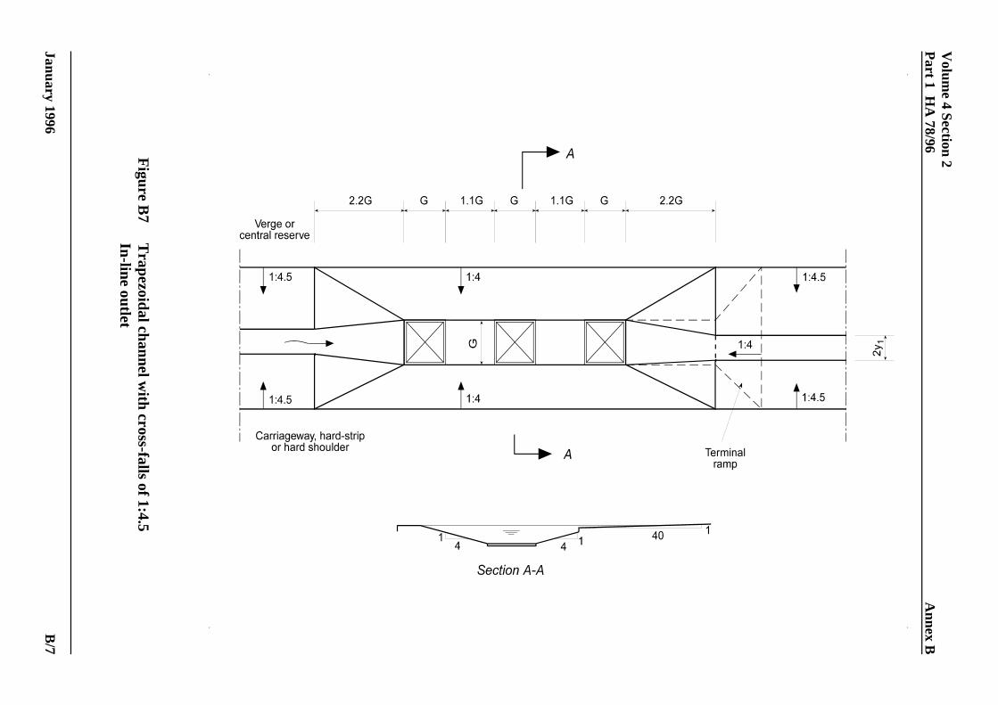
3.12 The in-line outlet geometries recommended fortrapezoidal channels are shown in Figures B7 and B9. The width of the gratings is determined by:
G/y = 3.0 (6)1
3.13 The length of H is given by Equation (4). Thecomments in Paragraph 3.9 regarding the number ofgratings, the importance of a gradual transition and thelocal side slopes apply also to this case.
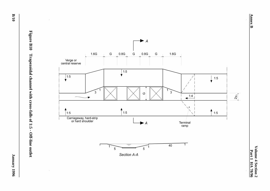
3.14 The off-line geometries recommended areshown in Figure B8 and B10. The width of the gratingsis determined by:
G/y $ 4.0 (7)1
3.15 The length H is given by Equation (4). As forthe in-line outlet, the comments in Paragraph 3.9 arealso applicable to this case.
Terminal outlets
3.16 The requirement that surface water channelsshould not have any sides steeper than 1:4 applies alsoto the geometry of terminal outlets. When not protectedby a safety barrier, surface water channels musttherefore terminate with a smooth transition, withoutabrupt changes in level or width. Examples ofrecommended terminal outlets are shown in dashedlines in Figures B5 to B10. The terminal ramps shouldbe built at a certain minimum distance from the gratingfurthest downstream. This reduces the probability ofblockage of the gratings by debris since some of thedebris will tend to accumulate in the area between thegratings and the terminal ramp. For in-line and off-lineoutlets in triangular channels, this distance should equalthe grating width. For in-line and off-line outlets intrapezoidal channels, the recommended distances aregiven in terms of the grating width, G, and are shown inFigures B7 to B10.

Fd '28.6Qd
B 2.5d
(8)
Fs '24.6Qs
B 2.5s
(9)
Fd '25.6 Qd
B 2.5d
(10)
Fs '22.2 Qs
B 2.5s
(11)
Fd '29.8 Qd
B 2.5d
(12)
Fs '25.5 Qs
B 2.5s
(13)
Volume 4 Section 2 Chapter 4Part 1 HA 78/96 Hydraulic Design of Outlets
January 1996 PAPER COPIES OF THIS ELECTRONIC DOCUMENT ARE UNCONTROLLE D 4/1
4. HYDRAULIC DESIGN OF OUTLETS
General procedure
4.1 The design procedure involves choosing thetype of outlet (in-line, off-line or weir outlet) and thenumber of gratings needed to achieve the requiredperformance. The geometry of each type of outlet ispredetermined as described in Paragraphs 3.4 to 3.16and illustrated in Figures B5 to B10. The size of thegratings is related to the size of the channel inaccordance with Equations (3) to (7).
4.2 The performance of an outlet should bedetermined for channel-full conditions (correspondingto the design flow depth y ) but checks of the1
performance for surcharged flow conditions may alsobe carried out.
4.3 For intermediate outlets, design curves arepresented which give the number of gratings needed toachieve the required performance of the outlet (FiguresB11 to B22). For terminal outlets the number ofgratings is obtained from Tables A1 and A2. The flowconditions are represented by a non-dimensionalnumber so that the design procedure is valid for all sizesof channel having the same cross-sectional shape(triangular or trapezoidal).
4.4 The in-line and off-line designs are suitableonly for channels with small to moderate longitudinalslopes. In steep channels (typically >1:50) the designprocedure to adopt is described in Chapter 5.
Intermediate outlets
4.5 The hydraulic design of intermediate outlets isbased on a number of curves (Figures B11 to B22)developed for channel-full and surcharged conditions. These curves show the variation of the efficiency ofeach outlet with the flow conditions.
4.6 In the curves, the flow conditions arerepresented by a non-dimensional number: F ford
channel-full and F for surcharged channel. s
4.7 For triangular channels:
and
where
Q is the approach flow (in m /s) corresponding tod3
channel-full conditions (ie flow depth y )1
Q is the approach flow (in m /s) corresponding tos3
surcharged conditions (ie flow depth y )s
B is the surface width of the flow (in m) ford
channel-full conditions
B is the surface width of the flow (in m) in as
surcharged channel neglecting the width ofsurcharge on the hard strip or hard shoulder -see Figures B1 and B2.
For the estimation of Q and Q refer to Chapter 2. d s
4.8 For trapezoidal channels with cross-falls of1:4.5:
and
4.9 For trapezoidal channels with cross-falls of 1:5:
and
4.10 In Equations (5), (8), (10) and (12) thenumerical constants are chosen so that critical flowunder channel-full conditions corresponds to a value ofF = 1. Equations (9), (11) and (13) are similarlyd
Chapter 4 Volume 4 Section 2Hydraulic Design of Outlets Part 1 HA 78/96
January 19964/2
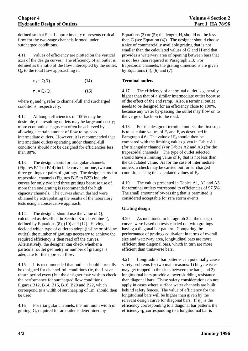
defined so that F = 1 approximately represents critical Equations (3) or (5); the length, H, should not be lesss
flow for the two-stage channels formed under than G (see Equation (4)). The designer should choosesurcharged conditions. a size of commercially available grating that is not
4.11 Values of efficiency are plotted on the vertical provides a waterway area of opening between bars thataxis of the design curves. The efficiency of an outlet is is not less than required in Paragraph 2.3. Fordefined as the ratio of the flow intercepted by the outlet, trapezoidal channels, the grating dimensions are givenQ , to the total flow approaching it: by Equations (4), (6) and (7).i
0 = Q /Q (14) Terminal outletsd i d
0 = Q /Q (15)s i s
where 0 and 0 refer to channel-full and surchargedd s
conditions, respectively.
4.12 Although efficiencies of 100% may bedesirable, the resulting outlets may be large and costly;more economic designs can often be achieved byallowing a certain amount of flow to by-passintermediate outlets. However, it is recommended thatintermediate outlets operating under channel-fullconditions should not be designed for efficiencies lessthan 80%.
4.13 The design charts for triangular channels(Figures B11 to B14) include curves for one, two andthree gratings or pairs of gratings. The design charts fortrapezoidal channels (Figures B15 to B22) includecurves for only two and three gratings because use ofmore than one grating is recommended for highcapacity channels. The curves shown dashed wereobtained by extrapolating the results of the laboratorytests using a conservative approach.
4.14 The designer should use the value of Qd
calculated as described in Section 3 to determine Fd
defined by Equations (8), (10) and (12). Havingdecided which type of outlet to adopt (in-line or off-lineoutlet), the number of gratings necessary to achieve therequired efficiency is then read off the curves. Alternatively, the designer can check whether aparticular outlet geometry or number of gratings isadequate for the approach flow.
4.15 It is recommended that outlets should normallybe designed for channel-full conditions (ie, the 1-yearreturn period event) but the designer may wish to checkthe performance for surcharged flow conditions. Figures B12, B14, B16, B18, B20 and B22, whichcorrespond to a width of surcharging of 1m, should thenbe used.
4.16 For triangular channels, the minimum width ofgrating, G, required for an outlet is determined by
smaller than the calculated values of G and H and that
4.17 The efficiency of a terminal outlet is generallyhigher than that of a similar intermediate outlet becauseof the effect of the end ramp. Also, a terminal outletneeds to be designed for an efficiency close to 100%,because any water by-passing the outlet may flow on tothe verge or back on to the road.
4.18 For the design of terminal outlets, the first stepis to calculate values of F and F as described ind s
Paragraph 4.6. The value of F should then bed
compared with the limiting values given in Table A1(for triangular channels) or Tables A2 and A3 (for thetrapezoidal channels). The type of outlet selectedshould have a limiting value of F that is not less thand
the calculated value. As for the case of intermediateoutlets, a check may be carried out for surchargedconditions using the calculated values of F . s
4.19 The values presented in Tables A1, A2 and A3for terminal outlets correspond to efficiencies of 97.5%. The small amount of by-passing that is permitted isconsidered acceptable for rare storm events.
Grating design
4.20 As mentioned in Paragraph 3.2, the designcurves were based on tests carried out with gratingshaving a diagonal bar pattern. Comparing theperformance of gratings equivalent in terms of overallsize and waterway area, longitudinal bars are moreefficient than diagonal bars, which in turn are moreefficient than transverse bars.
4.21 Longitudinal bar patterns can potentially causesafety problems for two main reasons: 1) bicycle tyresmay get trapped in the slots between the bars; and 2)longitudinal bars provide a lower skidding resistancethan diagonal bars. These safety considerations do notapply in cases where surface water channels are builtbehind safety fences. The value of efficiency for thelongitudinal bars will be higher than given by therelevant design curve for diagonal bars. If 0 is theD
efficiency corresponding to a diagonal bar pattern, theefficiency 0 corresponding to a longitudinal bar isL

Volume 4 Section 2 Chapter 4Part 1 HA 78/96 Hydraulic Design of Outlets
January 1996 PAPER COPIES OF THIS ELECTRONIC DOCUMENT ARE UNCONTROLLE D 4/3
approximately given by :
0 = 0.5 + 0.5 0 (16)L D
4.22 The use of gratings with bars transverse to thedirection of the flow has been found to reduce the outletefficiency considerably and is therefore not covered bythis document.

Lw
Bt
' 1 %1
tan 2(17)
Volume 4 Section 2 Chapter 5Part 1 HA 78/96 Weir Outlet
January 1996 PAPER COPIES OF THIS ELECTRONIC DOCUMENT ARE UNCONTROLLE D 5/1
5. WEIR OUTLET
5.1 The flow-collecting efficiency of an outletdecreases as the steepness of the surface water channeland the velocity of the flow within it are increased. When the types of grated outlet illustrated in Figures B5to B10 are not able to provide the necessary level ofperformance (minimum efficiencies of 80% forintermediate outlets and 97.5% for terminal outlets), analternative layout termed a weir outlet should be used. In this type of outlet, the water is gradually directedaway from the carriageway and discharged over a sideweir into a collecting channel in the verge. In order toprevent wheels of vehicles dropping into the channel, asafety fence will normally need to be installed along thecarriageway-side of the collecting channel. Therecommended layout of the weir outlet is shown inFigures B23 and B24.
5.2 In order to allow the high-velocity flow in thesurface water channel to be turned towards the side weirwithout spilling out on to the carriageway, it isnecessary for the channel to be flowing only partly fullimmediately upstream of the outlet. It is recommendedthat this condition should be achieved by locallywidening the surface water channel in a transitionsection upstream of the outlet (see Figure B24); withthis design the overall depth and cross-falls of thechannel are kept constant and the width increasedsufficiently to reduce the design flow depth approachingthe outlet to two-thirds of the overall channel depth.
5.3 The total length, L , of the weir outlet is madew
up of a straight length, L , parallel to the edge of thes
carriageway and a length, L , at an angle 2 to thea
carriageway (see Figure B24). L is equal to B , thes t
surcharged width of the channel at the downstream endof the transition, so that:
5.4 The values of the ratio L /B and 2 are obtainedw t
from Figure B25 and are dependent on the non-dimensional number, F , in Equation (8) which isd
calculated for design flow conditions in the upstreamsurface water channel. As shown in Figure B24, thestraight and angled portions of the weir outlet should bejoined by a curved side transition with its upstream endat the mid-point of the length L .s
Triangular channels
5.5 The procedure for designing weir outlets fortriangular surface water channels is explained in theflow chart of Figure B26. In the transition sectionupstream of the outlet (see Figure B24), the cross-fallsand overall depth remain constant but the triangularshape is transformed to a trapezoidal cross-section inorder to reduce the flow depth approaching the weiroutlet. The length, L , of the transition and the baset
width, B , at the downstream end are as follows:b
1:5 cross-falls:- L = 25 y (18)t 1
B = 5 y (19)b 1
where y is the design flow depth in the surface water1
channel upstream of the transition (see Figure B1).
Trapezoidal channels with cross-falls of 1:4.5
5.6 The procedure for designing weir outlets fortrapezoidal surface water channels with side slopes of1:4.5 is explained in the flow chart of Figure B27. Inthe transition section upstream of the outlet, the cross-falls and overall depth remain constant but the basewidth is increased (from a value of 2y at the upstream1
end) in order to reduce the flow depth approaching theweir outlet. The length, L , of the transition and thet
base width, B , at the downstream end are as follows:b
1:4.5 cross-falls:- L = 25 y (20)t 1
B = 7 y (21)b 1
where y is the design flow depth in the surface water1
channel upstream of the transition (see Figure B2).
Trapezoidal channels with cross-falls of 1:5
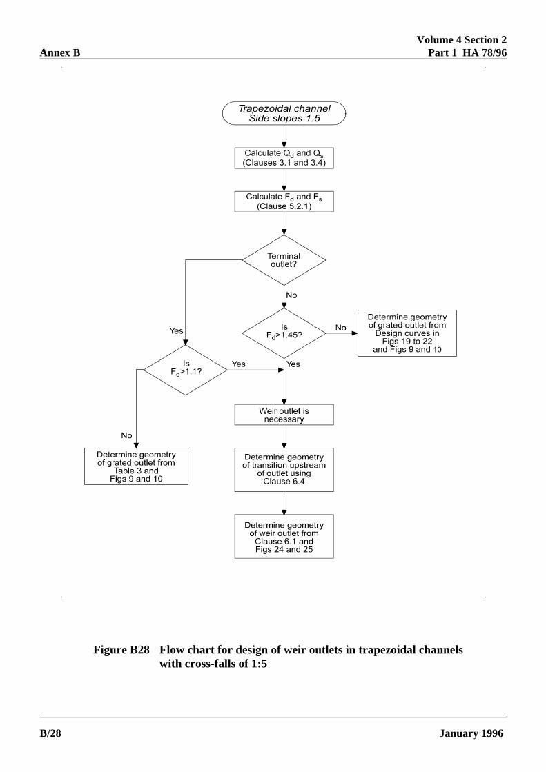
5.7 The procedure for designing weir outlets fortrapezoidal surface water channels with side-slopes of1:5 is explained in the flow chart of Figure B28. In thetransition section upstream of the outlet, the cross-fallsand overall depth remain constant but the base width isincreased (from a value of 2y at the upstream end) in1
order to reduce the flow depth approaching the weiroutlet. The length, L , of the transition and the baset
width, B , at the downstream end are as follows:b

Chapter 5 Volume 4 Section 2Weir Outlet Part 1 HA 78/96
January 19965/2
1:5 cross-falls:- L = 30 y (22)t 1
B = 8 y (23)b 1
where y is the design flow depth in the surface water1
channel upstream of the transition (see Figure B2).

Z 'D2% 0.23 Q2
D 4(24)
Volume 4 Section 2 Chapter 6Part 1 HA 78/96 General Recommendations on Design of Outfall Structures
January 1996 PAPER COPIES OF THIS ELECTRONIC DOCUMENT ARE UNCONTROLLE D 6/1
6. GENERAL RECOMMENDATIONS ONDESIGN OF OUTFALL STRUCTURES
6.1 An outfall conveys water from one or more 6.5 Provided the chamber below the outlet isoutlets in a surface water channel to a suitable discharge designed to trap sediment, the outgoing pipe from thepoint. The design of an outfall may vary considerably chamber may be connected directly to a collector pipedepending on the general topography and nature of the by means of a 45E Y junction without the need for aground, the layout of the road scheme and whether the manhole at the junction position.water is discharged to a watercourse, a soakaway or abelow-ground piped system. 6.6 If a weir outlet is used (see Chapter 5), the
6.2 A chamber or gully pot should be located should be deep enough to allow the outlet to dischargebelow or immediately adjacent to each outlet to collect freely when the surface water channel is flowing undersediment carried with the flow from the surface water surcharged conditions. The design flow depth, J (in m),channel. Standard circular gully pots have a limited can be estimated from the equation:hydraulic capacity and it is recommended that theyshould not be used for flow rates exceeding 5 l/s unless J = 4.82 (E Q / A ) (25)their suitability has been determined by test.
6.3 The plan shape of the chamber will be design rate of flow (in m /s). The overall depth of thedetermined by the layout of the gratings forming the channel is obtained by adding 0.15m to the value of J.outlet. The invert of the outgoing pipe from the The top width of the channel should not be lesschamber should be set a minimum of 300mm above the than 0.5m.bottom of the chamber to retain an adequate volume ofsediment. 6.7 It is recommended that the collecting channel
6.4 The invert level of the outgoing pipe should be with a removable cover in order to still the flow andchosen so that the water level in the chamber does not allow sediment to be collected. The sizes of therise high enough to prevent flow discharging freely chamber and the outgoing pipe should be determined infrom the surface water channel into the outlet. For accordance with the general recommendations indesign, it is recommended that the water level in the Paragraphs 6.3 to 6.6.chamber should be at least 150mm below the undersideof the gratings when the outlet is receiving flow fromthe channel under surcharged conditions. The height Z(in m), of the water surface in the chamber above theinvert of the outgoing pipe can be estimated from theequation:
where D is the diameter of the pipe (in m) and Q is theflow rate (in m /s) in the chamber corresponding to3
surcharged conditions in the surface water channel. Thegradient and diameter of the outgoing pipe should bedetermined from standard flow tables or resistanceequation so that the pipe is just flowing full undersurcharged conditions.
collecting channel into which flow drops from the weir
4 4 5
where E is the top width of flow (in m) and Q is the3
below a weir outlet should discharge into a chamber

Volume 4 Section 2 Chapter 7Part 1 HA 78/96 Spacing of Outlets With By-Passing
January 1996 PAPER COPIES OF THIS ELECTRONIC DOCUMENT ARE UNCONTROLLE D 7/1
7. SPACING OF OUTLETS WITH BY-PASSING
7.1 When by-pass flow is allowed in the design ofan intermediate outlet, ie when efficiencies lower than100% are adopted, the design of the channeldownstream of the outlet is no longer directly coveredby HA 37. In this case the spacing of the outlets needsto be reduced in order to allow for the additional flowby-passing the upstream outlet. As an interim measure,it is recommended that the distance L between outlets,as determined in HA 37, should be reduced to 0L,where 0 is the adopted design efficiency of theupstream outlet.

Volume 4 Section 2 Chapter 8Part 1 HA 78/96 Overall Design of Surface Water Channel Systems
January 1996 PAPER COPIES OF THIS ELECTRONIC DOCUMENT ARE UNCONTROLLE D 8/1
8. OVERALL DESIGN OF SURFACE WATERCHANNEL SYSTEMS
8.1 In order to obtain the most cost-effectivesolution for a drainage system using surface waterchannels, the designer should consider the total cost ofthe channels and outlets together. In some cases, adesign based on the longest possible spacings betweenoutlets may not be the optimum solution. Shorterspacings will require more outlets but these may besmaller and cheaper; also, the shorter distance betweenoutlets will allow use of smaller sizes of surface waterchannel. The effect on the total cost of allowingdifferent amounts of by-passing at intermediate outletsshould also be considered. For each option therelationship between channel size and required outletspacing should be determined from HA 37, and theeffect of allowing by-passing at intermediate outletsshould be estimated according to Chapter 7.

R 'AP
'(1.2 x 0.12)/2
2(0.1202%0.62)0.5'
0.0721.224
' 0.0588m
Qd '0.072 x 0.05882/3 x 0.005½
0.013' 0.0592m3/s
Fd '28.6 x 0.0592
1.22.5' 1.07
Fs '24.6 x 0.1006
1.3252.5' 1.22
Volume 4 Section 2 Chapter 9Part 1 HA 78/96 Worked Examples
January 1996 PAPER COPIES OF THIS ELECTRONIC DOCUMENT ARE UNCONTROLLE D 9/1
9. WORKED EXAMPLES
9.1 Example 1
Design an intermediate in-line outlet in a triangularsurface water channel having the followingcharacteristics:
cross-falls 1:5design flow depth 0.120mlongitudinal channel gradient 1:200
=0.005 Manning's roughness coefficient(average condition) 0.013
Adopt an efficiency of 100% for the outlets and acarriageway cross-fall of 1:40.
The flow in the channel is calculated from Equation (1)but first it is necessary to calculate the hydraulic radiusR using Equation (2):
The channel-full flow Q is then given by:d
The flow Q for surcharging of 1m width of the hard-s
strip or hard-shoulder is determined from Figure B3. For B = 1.2m, Q /Q = 1.7 and therefore:d s d
Q = 1.7 x 0.0592 = 0.1006m /ss3
Then calculate F using Equation (8):d
Calculate also F using Equation (9). It is firsts
necessary to calculate B . For a carriageway cross-falls
of 1:40, 1m of surcharging corresponds to 0.025m ofwater depth above the channel-full depth, ie a totaldepth of 0.145m.
Therefore
B = 5 (0.120 + 0.145) = 1.325ms
Figures B11 and B12 are appropriate for the design ofin-line intermediate outlets in triangular channels.
The designer should begin by considering channel-fullconditions, which are described by Figure B11. Adopting an efficiency of 100%, Figure B11 shows theneed for two pairs of gratings installed on the slopingsides of the channel. Figure B12 shows that two pairsof gratings are also satisfactory for surchargedconditions.
The size of the gratings (G is width and H is length) iscalculated as described in Paragraphs 3.6 and 3.7:
4.5 # G/0.120 # 5.1
and H $ G
Taking the smallest dimensions allowed gives
G = 0.120 x 4.5 = 0.540m
H = G = 0.540m
The designer should therefore choose fromcommercially available gratings, gratings with widthand length not smaller than 540mm. The totalwaterway area of the slots should not be less than0.44G or 0.128m (Paragraph 3.2).2 2
As shown in Figure B5, the longitudinal distancebetween the two pairs of gratings should be at leastequal to 1.7 x 0.540 = 0.918m if a grating of width0.540m is chosen.
9.2 Example 2
Design a terminal off-line outlet in a triangular surfacewater channel with the same characteristics as inExample 1.
The flow in the channel for channel-full conditions Qd
was calculated to be 0.0592m /s and for surcharged3

R 'AP'
12 (0.30 % 1.80) x 0.15
0.3 % 0.2 (0.152 % 0.752) ½
'0.15751.830
' 0.0861 m
Qd '0.1575 x 0.08612/3 x 0.0021/2
0.013' 0.106 m3/s
Fd '29.8 x 0.106
1.82.5' 0.73
Fs '25.5 x 0.159
1.9252.5' 0.79
Chapter 9 Volume 4 Section 2Worked Examples Part 1 HA 78/96
January 19969/2
conditions Q was found to be 0.1006m /s. The valuess3
of F and F were, respectively, 1.07 and 1.22.d s
Table A1 should be consulted for the design of terminaloutlets in triangular channels. Checking first forchannel-full conditions it can be seen that for an off-lineoutlet, one single grating would be able to intercept theflow satisfactorily (F = 1.2 in Table A1 is bigger thand
the calculated F = 1.07). However, when checking ford
surcharged conditions, Table A1 indicates the need for aminimum of two gratings (F = 1.0 in the table iss
smaller than the calculated F = 1.22). The designer is,s
in this case, recommended to adopt two gratings notonly to account for floods of higher return period butalso for the possibility of partial blockage of thegratings by debris.
The size of the gratings is the same as in the previousexample. The longitudinal distance between the twogratings should be at least equal to 1.25 x 0.540 =0.675m. The total length of the outlet including oneupstream transition of 2.02m should be equal to orgreater than 4.9m (see Figure B6 for details of thegeometry).
9.3 Example 3
Design an intermediate off-line outlet in a trapezoidalsurface water channel having the followingcharacteristics:
cross-falls 1:5design flow depth 0.150mbase width 0.300mlongitudinal channel gradient 1/500
=0.0020
Manning's roughness coefficient(average condition) 0.013 Adopt an efficiency for the outlets of 85% and acarriageway cross-fall of 1:40.
The flow in the channel is calculated from Equation (1)but first it is necessary to calculate the hydraulic radiusR using Equation (2):
The channel-full flow is then given by:
The flow Q for surcharging of 1m width of the hard-s
strip or hard-shoulder is determined from Figure B4. For B = 1.8m, Q /Q = 1.5 and therefore:d s d
Q = 1.5 x 0.106 = 0.159 m /ss3
Then calculate F using Equation (12):d
Assuming 0.025m of surcharging above the channel-fulldepth of 0.150m, the surcharged width of the channel is:
B = 0.30 + 5 (0.150 + 0.175) = 1.925ms
The corresponding value of F is found from Equations
(13):
Figures B21 and B22 are appropriate for the design ofoff-line outlets in trapezoidal channels with cross-fallsof 1:5. For channel-full conditions, Figure B21 showsthat for F = 0.73 a minimum of two gratings is requiredd
to achieve a collection efficiency of 85%. Checking forsurcharged conditions using Figure B22, it can be seenthat for F = 0.79 two gratings are also satisfactory ands
just satisfy the efficiency criterion of 85%.
The dimensions of the gratings are calculated asdescribed in Paragraph 3.14:
G $ 4.0 x 0.150 = 0.600 m
H $ 0.600 m
The total waterway area of the slots should not be lessthan 0.44G or 0.158m (Paragraph 3.2). The layout of2 2
the outlet is similar to the one shown in Figure B10 butwith only two gratings. The minimum overall length ofthe outlet is 6.0G or 3.60m including two 0.96m longtransitions.
9.4 Example 4
Design a suitable terminal outlet for a triangular surfacewater channel having the following characteristics :

Qd '0.072 x 0.05882/3 x 0.041/2
0.013' 0.168m3/s
Fd '28.6 x 0.168
1.22.5' 3.05
Volume 4 Section 2 Chapter 9Part 1 HA 78/96 Worked Examples
January 1996 PAPER COPIES OF THIS ELECTRONIC DOCUMENT ARE UNCONTROLLE D 9/3
cross-falls 1:5 The straight and angled portions of the weir have thedesign flow depth 0.120m following lengths:longitudinal channel gradient 1:25 = 0.04 L = B . 2.0m
Manning's roughness coefficient L = L - L = 8.0 - 2.0 = 6.0m(average condition) 0.013
The flow in the channel is calculated using equation (1)as in Example 1 :
A = 0.072m2
R = 0.0588m
The value of F is calculated using equation (8) :d
From Table A1 (and the flow chart in Figure B26) itcan be seen that, because F > 2.30, neither an in-line ord
an off-line outlet is adequate and therefore a weir outletis required. Following the procedure in Figure B26, thefirst step is the design of the transition section upstreamof the weir outlet. Using Equation (18), the requiredlength of the transition is:
L = 25 x 0.120 = 3.000mt
Over this distance, the triangular profile of the surfacewater channel is transformed to a trapezoidal shape withthe same depth and cross-falls but with a base widthgiven by Equation (19) of:
B = 5 x 0.120 = 0.600mb
Assuming 0.025m of surcharging above the channel-fulldepth of 0.120m, the surcharged width at thedownstream end of the transition is:
B = 5 x 0.120 + 0.600 + 5 x 0.145 t
= 1.925m
The dimensions of the weir outlet are determined fromFigure B25. For a value of F = 3.05, this gives:d
L = 4.15 x 1.925 = 8.0mw
2 = 17.6E
s t
a w s

Volume 4 Section 2 Chapter 10Part 1 HA 78/96 Glossary of Symbols
January 1996 PAPER COPIES OF THIS ELECTRONIC DOCUMENT ARE UNCONTROLLE D 10/1
10. GLOSSARY OF SYMBOLS
A Cross-sectional area of the flow
B Base width of trapezoidal channelb
B Surface width of flow for channel-full conditionsd
B Surface width of flow in surcharged channel neglecting the width of surcharge on hard-strip or hard-shoulders
B Value of B at downstream end of transition for weir outlett s
D Pipe diameter
E Top width of flow in collecting channel
e Distance between lower edges of pairs of in-line gratings in triangular channels
F Non-dimensional number for channel-fullo
F Non-dimensional number for flow in surcharged channels
G Width of gratings
H Length of gratings
J Design flow depth in collecting channel
L Distance between outlets
L Length of angled part of weir outleta
L Total length of weir outletw
L Length of straight part of weir outlet parallel to carriageways
L Length of transition for weir outlett
n Manning roughness coefficient
P Wetted perimeter of channel
Q Flow rate
Q Approach flow for channel-full conditionsd
Q Flow intercepted by outleti
Q Approach flow for surcharged conditionss
R Hydraulic radius of channel
S Longitudinal gradient

Chapter 10 Volume 4 Section 2Glossary of Symbols Part 1 HA 78/96
January 199610/2
S Value of equivalent longitudinal slopee
y Depth of the channel from the invert centreline to the lower edge of the carriageway (equal to design flow depth)1
y Depth of the channel from the invert centreline to the upper edge of the carriageway2
y Overall depth of channel from the invert centreline to the allowable level of surcharge3
Z Head of water above pipe invert
0 Efficiency
0 Efficiency of outlet for channel-full conditionsd
0 Efficiency of outlet for gratings with diagonal bar patternD
0 Efficiency of outlet for gratings with longitudinal bar patternL
0 Efficiency of outlet for surcharged conditionss
2 Angle of weir outlet

Volume 4 Section 2 Chapter 11Part 1 HA 78/96 References
January 1996 PAPER COPIES OF THIS ELECTRONIC DOCUMENT ARE UNCONTROLLE D 11/1
11. REFERENCES
Design Manual for Roads and Bridges (DMRB)
1. HA 37. “Hydraulic Design of Road-EdgeSurface Water Channels". (DMRB 4.2.1)
2. Amendment No. 1 to HA 37. (DMRB 4.2.1)
Manual of Contract Documents for Highway Works(MCHW)
3. Highway Construction Details. (MCHW3)
4. "Surface Water Channels and Outfalls:Recommendations on Design", HR Wallingford(1996), Report SR 406

Volume 4 Section 2 Chapter 12Part 1 HA 78/96 Enquiries
January 1996 PAPER COPIES OF THIS ELECTRONIC DOCUMENT ARE UNCONTROLLE D 12/1
12. ENQUIRIES
All technical enquiries or comments on this Advice Note should be sent in writing as appropriate to:
Head of DivisionRoad Engineering and Environmental DivisionSt Christopher HouseSouthwark Street J A KERMANLondon SE1 OTE Head of Division
The Deputy Chief EngineerThe Scottish Office Development DepartmentNational Roads DirectorateVictoria Quay N B MACKENZIE Edinburgh EH6 6QQ Deputy Chief Engineer
Head of Roads Engineering (Construction) DivisionWelsh OfficeY Swyddfa GymreigGovernment BuildingsTy Glas RoadLlanishen B H HAWKERCardiff CF4 5PL Head of Roads Engineering (Construction) Division
Assistant Chief Engineer (Works)Department of the Environment for Northern IrelandRoads Service HeadquartersClarence Court10-18 Adelaide Street D O'HAGANBelfast BT2 8GB Assistant Chief Engineer (Works)

Volume 4 Section 2Part 1 HA 78/96 Annex A
January 1996 PAPER COPIES OF THIS ELECTRONIC DOCUMENT ARE UNCONTROLLE D A/1
TABLES
Table A1 Triangular channels: Limiting values of F and F for terminal outletsd s
No of Gratings (or Pairs of Gratings)
Type of Outlet 1 2 3
In-Line Outlet:
Channel full (F ) 0.95 2.0 2.3d
Surcharged (F ) 0.80 1.8 2.1s
Off-Line Outlet:
Channel full (F ) 1.2 1.4 2.0d
Surcharged (F ) 1.0 1.3 1.7s
Table A2 Trapezoidal channel with cross-falls of 1:4.5: Limiting values of F and F for terminal outletsd s
No of Gratings
Type of Outlet 2 3
In-Line Outlet:
Channel full (F ) 0.55 0.85d
Surcharged (F ) 0.40 0.70s
Off-Line Outlet:
Channel full (F ) 1.0 1.3d
Surcharged (F ) 0.9 1.2s
Table A3 Trapezoidal channel with cross-falls of 1:5: Limiting values of F and F for terminal outletsd s
No of Gratings
Type of Outlet 2 3
In-Line Outlet:
Channel full (F ) 0.45 0.65d
Surcharged (F ) 0.30 0.50s
Off-Line Outlet:
Channel full (F ) 0.75 1.1d
Surcharged (F ) 0.65 1.0s

Volum
e 4 Section 2
Part 1 H
A 78/96
Annex B
January 1996P
AP
ER
CO
PIE
S O
F T
HIS
ELE
CT
RO
NIC
DO
CU
ME
NT
AR
E U
NC
ON
TR
OLLE
DB
/1
Figure B
1C
ross-sectional shape of triangular channel
FIG
UR
ES

Volum
e 4 Section 2
Annex B
Part 1 H
A 78/96
January 1996B
/2
Figure B
2C
ross-sectional shape of trapezoidal channels

Volum
e 4 Section 2
Part 1 H
A 78/96
Annex B
January 1996P
AP
ER
CO
PIE
S O
F T
HIS
ELE
CT
RO
NIC
DO
CU
ME
NT
AR
E U
NC
ON
TR
OLLE
DB
/3
Figure B
3R
elationshi[p between surcharge and channel-full flow
s:T
riangular Channels

Volum
e 4 Section 2
Annex B
Part 1 H
A 78/96
January 1996B
/4
Figure B
4R
elationship between surcharged and channel-full flow
s:T
rapezoidal channels

Volum
e 4 Section 2
Part 1 H
A 78/96
Annex B
January 1996P
AP
ER
CO
PIE
S O
F T
HIS
ELE
CT
RO
NIC
DO
CU
ME
NT
AR
E U
NC
ON
TR
OLLE
DB
/5
Figure B
5T
riangular channelIn-line outlet

Volum
e 4 Section 2
Annex B
Part 1 H
A 78/96
January 1996B
/6
Figure B
6T
riangular Channel
Off-line outlet
Volum
e 4 Section 2
Part 1 H
A 78/96
Annex B
January 1996P
AP
ER
CO
PIE
S O
F T
HIS
ELE
CT
RO
NIC
DO
CU
ME
NT
AR
E U
NC
ON
TR
OLLE
DB
/7
Figure B
7T
rapezoidal channel with cross-falls of 1:4.5
In-line outlet

Volum
e 4 Section 2
Annex B
Part 1 H
A 78/96
January 1996B
/8
Figure B
8T
rapezoidal channel with cross-falls of 1:4.5 - O
ff-line outlet

Volum
e 4 Section 2
Part 1 H
A 78/96
Annex B
January 1996P
AP
ER
CO
PIE
S O
F T
HIS
ELE
CT
RO
NIC
DO
CU
ME
NT
AR
E U
NC
ON
TR
OLLE
DB
/9
Figure B
9T
rapezoidal channel with cross-falls of 1:5
In-line outlet
Volum
e 4 Section 2
Annex B
Part 1 H
A 78/96
January 1996B
/10
Figure B
10T
rapezoidal channel with cross-falls of 1:5 - O
ff-line outlet

Volum
e 4 Section 2
Part 1 H
A 78/96
Annex B
January 1996P
AP
ER
CO
PIE
S O
F T
HIS
ELE
CT
RO
NIC
DO
CU
ME
NT
AR
E U
NC
ON
TR
OLLE
DB
/11
Figure B
11D
esign curves. Triangular channel - In-line outlet
Channel full

Volum
e 4 Section 2
Annex B
Part 1 H
A 78/96
January 1996B
/12
Figure B
12D
esign curves. Triangular channel - In-line outlet
Surcharged channel

Volum
e 4 Section 2
Part 1 H
A 78/96
Annex B
January 1996P
AP
ER
CO
PIE
S O
F T
HIS
ELE
CT
RO
NIC
DO
CU
ME
NT
AR
E U
NC
ON
TR
OLLE
DB
/13
Figure B
13D
esign curves. Triangular channel - O
ff-line outletC
hannel full

Volum
e 4 Section 2
Annex B
Part 1 H
A 78/96
January 1996B
/14
Figure B
14D
esign curves. Triangular channel - O
ff-line outletS
urcharged Channel

Volum
e 4 Section 2
Part 1 H
A 78/96
Annex B
January 1996P
AP
ER
CO
PIE
S O
F T
HIS
ELE
CT
RO
NIC
DO
CU
ME
NT
AR
E U
NC
ON
TR
OLLE
DB
/15
Figure B
15D
esign curves. Trapezoidal channel w
ith cross-falls of 1:4.5In-line outlet. C
hannel full

Volum
e 4 Section 2
Annex B
Part 1 H
A 78/96
January 1996B
/16
Figure B
16D
esign curves. Trapezoidal channel w
ith cross-falls of 1:4.5In-line outlet. S
urcharged channel

Volum
e 4 Section 2
Part 1 H
A 78/96
Annex B
January 1996P
AP
ER
CO
PIE
S O
F T
HIS
ELE
CT
RO
NIC
DO
CU
ME
NT
AR
E U
NC
ON
TR
OLLE
DB
/17
Figure B
17D
esign curves. Trapezoidal channel w
ith cross-falls of 1:4.5O
ff-line outlet. Channel full

Volum
e 4 Section 2
Annex B
Part 1 H
A 78/96
January 1996B
/18
Figure B
18D
esign curves. Trapezoidal channel w
ith cross-falls of 1:4.5O
ff-line outlet. Surcharged channel

Volum
e 4 Section 2
Part 1 H
A 78/96
Annex B
January 1996P
AP
ER
CO
PIE
S O
F T
HIS
ELE
CT
RO
NIC
DO
CU
ME
NT
AR
E U
NC
ON
TR
OLLE
DB
/19
Figure B
19D
esign curves. Trapezoidal channel w
ith cross-falls of 1:5In-line outlet. C
hannel full

Volum
e 4 Section 2
Annex B
Part 1 H
A 78/96
January 1996B
/20
Figure B
20D
esign curves. Trapezoidal channel w
ith cross-falls of 1:5In-line outlet. S
urcharged channel

Volum
e 4 Section 2
Part 1 H
A 78/96
Annex C
January 1996P
AP
ER
CO
PIE
S O
F T
HIS
ELE
CT
RO
NIC
DO
CU
ME
NT
AR
E U
NC
ON
TR
OLLE
DB
/21
Figure B
21D
esign curves. Trapezoidal channel w
ith cross-falls of 1:5O
ff-line outlet. Channel full

Volum
e 4 Section 2
Annex B
Part 1 H
A 78/96
January 1996B
/22
Figure B
22D
esign curves. Trapezoidal channel w
ith cross-falls of 1:5O
ff-line outlet. Surcharged channel

Volume 4 Section 2Part 1 HA 78/96 Annex C
January 1996 PAPER COPIES OF THIS ELECTRONIC DOCUMENT ARE UNCONTROLLE D B/23
Figure B23 Isometric view of weir outlet indicating possible location of safety fence

Volum
e 4 Section 2
Annex B
Part 1 H
A 78/96
January 1996B
/24
Figure B
24D
iagramm
atic layout of weir outlet and upstream
transition

Volume 4 Section 2Part 1 HA 78/96 Annex C
January 1996 PAPER COPIES OF THIS ELECTRONIC DOCUMENT ARE UNCONTROLLE D B/25
Figure B25 Variations of geometry of weir outlet with flow conditions

Volume 4 Section 2Annex B Part 1 HA 78/96
January 1996B/26
Figure B26 Flow chart for design of weir outlets in triangular channels

Volume 4 Section 2Part 1 HA 78/96 Annex C
January 1996 PAPER COPIES OF THIS ELECTRONIC DOCUMENT ARE UNCONTROLLE D B/27
Figure B27 Flow chart for design of weir outlets in trapezoidal channels with cross-falls of 1:4.5
Volume 4 Section 2Annex B Part 1 HA 78/96
January 1996B/28
Figure B28 Flow chart for design of weir outlets in trapezoidal channels with cross-falls of 1:5

Volum
e 4 Section 2
Part 1 H
A 78/96
Annex C
January 1996P
AP
ER
CO
PIE
S O
F T
HIS
ELE
CT
RO
NIC
DO
CU
ME
NT
AR
E U
NC
ON
TR
OLLE
DC
/1
Figure C
1E
xample of collecting cham
ber for in-line outlet intrapezoidal channel
EX
AM
PLE
S

Volume 4 Section 2Annex C Part 1 HA 78/96
January 1996C/2
Figure C2 Example of collecting chamber for in-line outlet in triangular channel