design of nonlinear robust excitation control for multimachine power systems
TRANSCRIPT

Design of nonlinear robust excitation control for multimachine power systems
C . S u n Z.Zhao Y.Sun 0. Lu
Inde.~ing t e r m : FI- c m t r o l thror,y, Feedback linecirisation, Power system. Robust control, System stuhility
Abstract: The nonlinear robust control problem of power systems is investigated in the paper. A novel controller for the generator excitation system is set up, based on a combination of H, control theory and an exact feedback linearisation approach. The properties of the controller are its complete decentralisation and robustness. The design is well suited to a multimachine system in that it is not based on a infinite bus approximation. Simulation performed on a 13- machine system shows that the proposed controller can not only improve the dynamic performance of the power system but also enhance the system stability, especially the large disturbance stability.
1 Introduction
The development of a large-scale interconnect power system and power technology brings about two notable results. First, the adequate system dynamic perform- ance depends more and more on the proper perform- ance of controls; secondly, it provides an excellent prerequisite for the full application of various advanced control patterns. Therefore, the proper controller is the important guarantee for power systems reliable opera- tion.
The generally utilised control patterns in power sys- tems are PID, PSS, LOEC (linear optimal excitation control) [I21 and nonlinear control [SI, based on differ- ential geometry theory in the design of which the per- turbation and the uncertain exogenous input of the system is not considered. But, the fact that the model uncertainty and uncertain disturbances are both incor- porated in power systems cannot be neglected. There- fore, the purpose of power system control is twofold: to ensure the stable operation of the system and to attenuate the influence of the disturbances (i.e. to acquire a robust controller).
For the above purpose, the application of the robust control theory in the analysis and design of a power
._____._--. - ____I-__-
0 IEE. 1996 IEE Proceedings online no. 19960349 Paper first received 20th June 1995 and in final revised form 13th December 1995 The authors are with the Department of Electrical Engineering, Tsinghua University. Beijing, 100084, China
system controller takes the researcher's attention. Some attempts to apply the robust control strategies have been reported in the literature [7, 9 -1 11. Rut until now, the applications of robust control theory all use the approximate linearised model under a special operation point of a power system. The disadvantage of this kind of controller is that it can only function well over a small range about the designed equilibrium point. We need to design the nonlinear robust controller by tak- ing the nonlinearity of the system into account. In this paper, the time domain H, control theory is utilised. A robust controller for multimachine generator excitation is proposed, based on the nonlinear syytem model. The salient features of the controller are its robustness (to the uncertainty of the network structure and parame- ters and to disturbances) and its decoupling.
2 system
The dynamic model for power system excitation con- trol design can be expressed as follows:
Dynamic model of multimachine power
s, = aw,
for a system with 17 i- 1 generators, i = 1, 2, ... n, sub- scription i denotes the ith generator. In eqn. 1,
n
P,; = G,&, + E;?
P,,a = - n w i
K.~E;,? sin(6,, - oij ) 3 = 1 i # 7
LJO
D , Eqt .E;i + I d z ( Z d z - x&i)
where 6, is rotor angle, rad.; 0); is speed, radls; E;j, Eqi are the transient voltage and the voltage behind the q- axis, respectively; P,,i, P(,;, P,, are mechanical power, electric power and damp power respectively; Hi, Tdoi are inertial time constant and the field winding time constant in seconds; Z'!;, I , are the q-axis and haxis current; xdi, xii are d-axis synchronous impedance and transient impedance.
Eqn. 1 can be written in vector form as:
x, = f , ( X ) + S i l ( X ) W i + g i 2 ( X ) U t ( 2 )
253

The control is ui = uf,, and the exogenous input is it ' i.
3 excitation
Nonlinear robust controller for generator
p =
3. I Consider a linear system described by equations of the form:
Preliminary-U, control theory [21
( 3 ) x = AX + B1.u: + B ~ u { ' y = CLZ
The first equation of this system describes a plant with state x E R" and control input U E R"' and subject to exogenous input variables w E R' which include distur- bances andlor references. The second equation defmes the output of the system.
The problem of linear H, control can be stated as the following terms: Given (A , B, , B2, C , ) and a real number y > 0, find, if possible, a matrix F such that ( A + B,F) has all eigenvalues in C, and the &-gain of the closed loop system:
(4) J: = (A + B ~ F ) x + B ~ w { y = ClZ
is strictly less than y, or what is the same, for each input w(*) E L2 [0, m), the response y(*) of eqn. 4 from the initial state X(0) = 0 is such that 5,- = ([ly(t)I[' + llu(t)l12) dt 5 yi I / W(t)i12 dt for some 0 < yfl < y. F exists if, and only if, the following Riccati equation
1 ATP + P A + Y P B l B T P - PB1BTP + CTCl= 0 (5)
has a non-negative solution P 2 0, and A + lly2 BIB:P - B,BifP has all eigenvalues in C. Under such condi- tions, the suboptimal control law and disturbance are as follows:
Y L
U* = -B,TPz
111, = -BTP.7: 2 1 ( 6 )
~ _ _ _ ~ 7 1
( + l ) Q ( r 2 - 1 ) f (y2-1)2
3 -f 27 3 2y5 ~ ~
(+1)4 ( r 2 - 1 ) 9 p/2-1)$
i 2y 5 2 y g
- 273 2y 3
2 4
(12) 4
~~~
3.2 Control law If the output of system (eqn 1) is chosen ds y , = A6, = 6, - 6,,, the transformation co-ordinate is defined as
xZ = [as,, ad?, 4 ( 7 ) Under the new co-ordinate, system (eqn 1) is converted to a linear system depicted by equations of the form
%;I = z72 ( 8 0 )
zz2 = ( 8 b )
(8c) z,3 = --(Pea + P,,) + d2%W WO
Ha For P,, = E;L Iqi + (x',~ xi,/) I'/, Iq,, if xqi 2 Y;, is consid- ered, such that P, , = E;,Iq; + E&, Then iewrite
254
eqn. Se:
= 21% + U:
where I,,, it.,' are defined as follows:
IC: = d 2 i u Z
With the above feedback linearisation, system or (eqn. 2) is transferred to a normal form as in which:
B1= [0 0 1IT
&=[O 0 1IT c1 = [ I 0 01
Therefore, when y > 1, A,, h,, h3 are all in C. There- fore. the suboptimal control law and disturbance of the linearised system can be obtained as.
t = -BTPZI = -P3lA& - P32Awz - P33w,
1 1 = ,B;PZ~ = - ( P ~ ~ A ~ , - P32aw, - P ~ ~ W , )
I Y2 (13)
Solving the simultaneous eqns. 10 and 13, we have the excitation control law for system (eqn. 3) as follows:
3.3 Realisation of the control law In the expression of the control strategy (eqn. 13), there are some unmeasurable variables such as E,,, E;, and 6,. In [8] an ODSS (observation decoupled state space) is set up to get some variables. In the light of the power system operation principles and dynamic properties. E,,, E;, and 6, can be replaced by the expression of the output variables of the system. This process is called the realisation of the control law.
If the salient pole effect is not taken into account, we have P,, = Eq,Iq, and the control strategy can be given in the form of:
TAP;, p,, ?Eq, - __ 4 q ) / d t P,1
0 3 1 1' AhLdt + p32adi: f r)33A0z)
(15) In eqn. 15, EqL = Qer.xd,/Vli + V,,, 6, = JdAco,dt where Vr, and Q,, are the terminal voltage and the reactive power of the generator, respectively.
3.4 Features of the control strategy From simple observation of the control law eqns. 13 and 15, one can find that: (i) The control law of each generator in system only has a relationship with the parameters and with some outputs of the generator itself, so that the control law is independent of the network parameters and structure and is decoupling with other generators in the system. (ii) In terms of the H, control theory, y should be as small as possible, in that i t is the &gain of the related linearised system. But, from the expression of the con- trol law (eqn. lS), one can find that the rather small y will result in the supersensitivity of the controller to the system's infinitesimal disturbances, so that the selection of y should be real. (iii) Because H , control theory is applied indirectly in the proposed controller design, the (sub)optimal prop- erty can only be said to apply to the related linear sys- tem.
4 Computer simulation
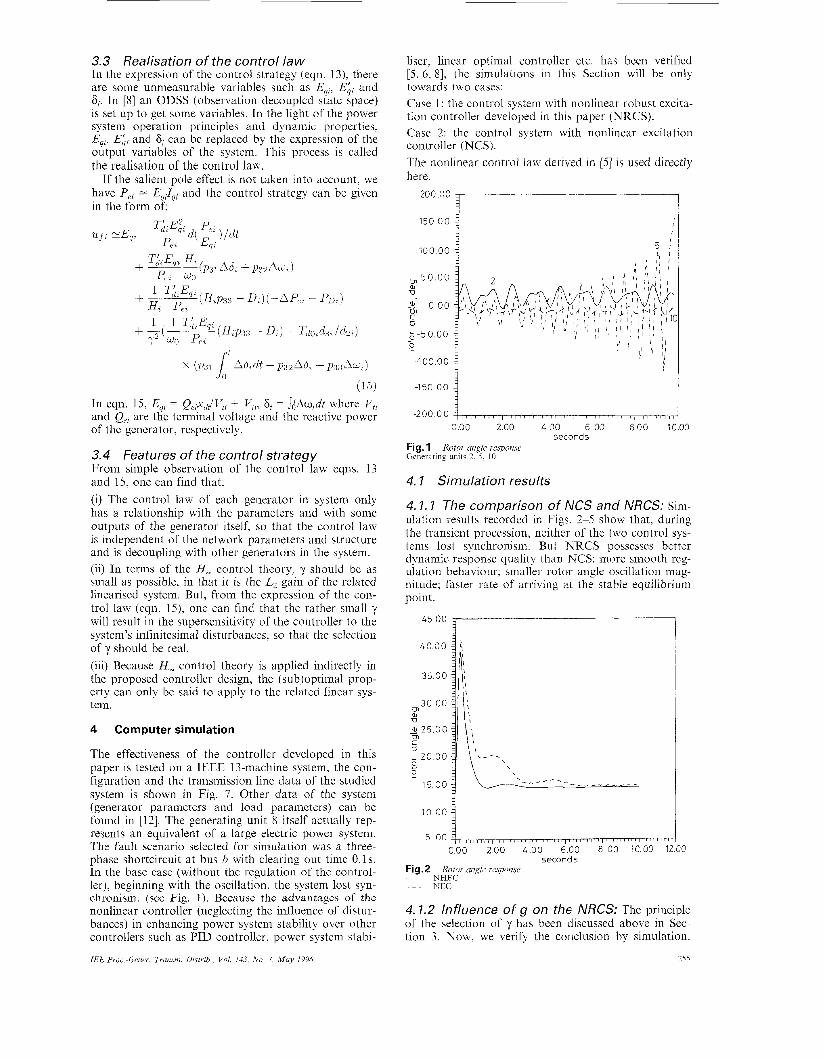
The effectiveness of the controller developed in this paper is tested on a IEEE 13-machine system, the con- figuration and the transmission line data of the studied system is shown in Fig. 7. Other data of the system (generator parameters and load parameters) can be found in [12]. The generating unit 8 itself actually rep- resents an equivalent of a large electric power system. The fault scenario selected for simulation was a three- phase shortcircuit at bus b with clearing out time 0.1s. In the base case (without the regulation of the control- ler), beginning with the oscillation, the system lost syn- chronism. (see Fig. 1 ) . Because the advantages of the nonlinear controller (neglecting the influence of distur- bances) in enhancing power system stability over other controllers such as PID controller. power system stabi-
IEE Proc.-Genev. Trunsni. Disfrih.. Vol. 143, No 3, Muy 19%
liser, linear optimal controller etc. has been verified [S, 6, 81, the simulations in this Section will be only towards two cases: Case 1 : the control system with nonlinear robust excita- tion controller developed in this paper (NRCS). Case 2: the control system with nonlinear excitation controller (NCS). The nonlinear control law derived in [5] is used directly here.
____--
150 OO 4 j
1 100.00
! -1 50.0 0
-200 00 g-mTrn,, , , , , , , " , , , , TT A 0.00 2.00 4.00 6.00 800 1000
seconds Fig. 1 Rotor angle response Generating units 2, 5 > I O
4. I Simulation results
4. I . I The comparison of NCS and NRCS: Sim- ulation results recorded in Figs. 2-5 show that, during the transient procession, neither of the two control sys- tems lost synchronism. But NRCS possesses better dynamic response quality than NCS: more smooth reg- ulation behaviour; smaller rotor angle oscillation mag- nitude; faster rate of arriving at the stable equilibrium point.
45.00 j-------- _I_
40 00
35 00
30 00 Cn a TJ
- a-25 00 m
L 20 00
2
C 0
c
15 00
10 00 j 5 00 immnpr , , , , , , , , , , / , , , , , , , / , , , / ,
000 200 400 600 8 00 1000 12GG seconds
Fig.2 Rotor angle ieqxjme ~ "FC
NEC
4.1.2 Influence of g on the NRCS: The principle of the selection of y has been discussed above in Sec- tion 3. Now, we verify the conclusion by simulation.
258

Choose the generating unit 2 as the studied case The transient behaviour of NRCS under different control- lers, in which y is changed, is recorded in Fig 6 From these curves we can see that, on the one hand, when y 1s chosen to be smaller, the system's oscillation magni- tude reduces. but in the dlter-regulation procedure. high frequency swing of rotor angle yields on the other hand, when y i s chosen to be larger, the system's oscil- lation magnitude incieases, the peiformance of the sps- tern turns worse, and the antidisturbance ability of the controller is apparently reduced
- 2 0 00
-30 00 000 2 0 0 L O O 6 0 0 8 0 0 1000 1200
s e c o n d s
' *O T--- 1
000 200 400 6 00 800 1000 1200 s e c o n d s
Fig.4 Voltuge respon5e Fault local generating unit 2 ( I ) NRCS (11) NCS
N H F C - -NEC
The same results are obtained when the same simula- tion procedure is performed on other generators in the system.
5 Conclusian
A novel nonlinear robust controller for generator exci- tation is developed in this paper, and its characteristics
256
000 2 0 0 400 600 800 1000 1 s e c o n d s
Fig. 5 Voltiige response Fault remoteie generating unit 9 (i) NRCS (ii) NCS ~- NHEC
UEC
5o O O T
4 0 00 1
10 001
0 00 1 0 00" ' 121& ' ' ' iYo;l ' ' ' ' : O T T F z Z ;
s e c o n d s Fig. 6 Rotoi ungle i espome 1 y = 2 0 2 y = l l , 3 y = 2 9
1 -
._... - - -
00
00
(decoupling and robustness to uncertainties of network a id exogenous input and model) are analysed. Simula- tion results of the controller applied to a sample test power system (IEEE 13-machine system) indicate the efficacy of the proposed controller in enhancing the system stability, especially the large disturbance stabil- ity Therefore, the design approach proposed in this paper i s progress on the design of the nonlinear con- troller.
6 References
1 ZAMES, G.: 'Feedback and optimal sensitivity: model reference transformations multiplicative seminorums, and approximate inverses', IEEE Trans., 1982, AC-26, pp. 301-320 VAN DER SCHAFT, A.: 'L2-gain analysis o f nonlinear systems and nonlinear state feedback H , control', IEEE Trans., 1992, AC-37, pp. 770-784 ISIDORI. A.: 'Disturbance attenuation and H, via measurement feedback in noiiliiiear systems', IEEE Trans., 1992, AC-37, pp. 1283- 1293
2
3
IEE Proc.-G~n~r. Transni. Di.strib.. Vol. 143, Nu. 3, Mat' 1996

4 FRANCIS, B.A.: ‘A course in H , control theory’ (Springer- Verlag, Berlin, 1987)
5 LU, Q., and SUN. Y.Z.: ‘The nonlinear control of power system’ (Acadcrnic Press, Beijing, 1993)
6 LU. Q.. and SUN, Y.Z.: ‘Nonlinear stabilising control of multi- machine systems’. IEEEIPES Summer Meeting, 1988,
7 OHTSUKA, K, , TANLGIJCHI, T., and YOKOKAWA, S.: ‘A H , optimal theory based generator control system’, IEEB Trcins., 1992, EC-7. pp. 108-1 13
8 CHAPMAN, J.W., ILTC. M.D., KING, C A . . ENG, L., arid KAUFMAN. H.: ‘Stabilising a power system via decentralised feedback lincarising excitation control’, IEEE Trcins.; 1993, PWRS-3, (3), pp. 830-838
9 KHAMMASH. M.H.. VITTAL. V.; and PAWLOSKI, C.D.: ‘Analysis of control performance for stability robustness of power system‘, lEEE Tram., 1994, PWRS-9, (4): pp. 1861-1867
10 ALIREZA SUNAI, S., YASUO, T., and SHINICHI, I.: ‘Robust generator control with robust observer’. IEE of Japan Power and Energy’94, Vol. 113. pp. 71-76
I 1 AHMED; S.S., and PETROIANU, A.: ‘Design of‘ decentralised robust excitation controllers based on 11, control theory’. lCPST’94, Beijing, Vol. 7, pp. 559-564
12 YU, Y.N.: ‘Electric power system dynamics’ (Academic Press, 1983)
1 1 3 26
7 Appendix
Fig. 7 shows a 13-machine power system c f
,LSL 4
Fig. 7 13-ml*chirzr power system
251