design of mooring system for met - ocean and … design.pdfdesign of mooring system for met - ocean...
TRANSCRIPT

1
DESIGN OF MOORING SYSTEM
FOR
MET - OCEAN AND TSUNAMI DATA COLLECTION
OCEAN OBSERVATION SYSTEMS
NATIONAL INSTITUTE OF OCEAN TECHNOLOGY
[Ministry of Earth Sciences, Government of India]
PALLIKARANAI, CHENNAI – 600 100
INDIA
FEBRUARY 2012

2
Chapter – 1
Introduction
The need to measure ocean surface and sub surface parameters in the water column for
extended periods to better understand ocean dynamics was a driving force that led to the
development of oceanographic moorings. Today’s moorings are used as ‘platforms’ from
which a variety of measurements can be made. These include not only the speed and
direction of currents, but also other physical parameters, such as conductivity (salinity),
temperature, as well as surface meteorology parameters.
Mooring is a compliant section between the surface buoy and the sinker weight, which
restraints buoys against the action of wind, wave and current forces. Moorings typically have
three basic components: an anchor, some type of chain or line to which instrumentation can
be attached, and flotation devices that keep the line and instrumentation from falling to the
sea bed. Shackles and links are typically used to connect mooring components and to secure
instruments in line. The choice of hardware, mooring line and flotation for a particular
application, as well as the size and design of the anchor, depends on the type of mooring and
the environment in which it is deployed.
Mooring is the most important aspect of any buoy program as it secures the floating platform
which houses the sensible and expensive sensors. Mooring design, that is the art of properly
selecting size, materials, shape, configuration, etc. of buoy system components has also
made great progress, often obtained by trial and error methods in olden days and by using
advanced software packages at present. The numerous mooring configurations have been
evolved to suit for different geographical locations under specified environmental conditions.
The general considerations in the design of moorings are,
The depth at the Deployment Location
Buoyancy of the surface float to be used
Sea bed conditions at the site such as Topography and soil conditions
The loads imposed on the mooring by the surface buoy due to the action of wind,
wave and current.
Expected loads on the mooring.
Required life of the mooring and the servicing facilities available.
Local conditions that cause wear and corrosion of the mooring components.
Deployment procedure.
Expected scope of the mooring (i.e.) mooring scope is the ratio between the total
mooring length to the depth at the deployment location.

3
Chapter - 2
Literature Survey
Oceanographic moorings fall into two broad categories surface and subsurface. The difference
between the two is that the surface mooring has a buoy floating on the ocean surface,
whereas the subsurface mooring does not. Although the two mooring types have similar
components, the capabilities of the two are very different. With a surface buoy, it is possible
to measure surface meteorology, real time data transmission and make very near surface
measurements in the upper ocean. The surface mooring, however, is exposed to ocean
storms with high wind and wave conditions and therefore must be constructed to withstand
the forces associated with the wind and waves. In addition, it may transmit some unwanted
motion to subsurface instruments if care is not taken. The subsurface mooring, on the other
hand, is away from the surface forcing and can be fabricated from smaller, lighter
components, which are less expensive and easier to handle. However, it is difficult to make
near-surface measurements from a subsurface mooring.
Growing interest in understanding interactions between the ocean and the atmosphere has
led to the development of surface moorings. The surface mooring is a unique structure. It
extends from above the surface to the ocean bottom, providing a platform from which both
meteorological and oceanographic measurements can be made in waters that range from
shallow to full ocean depth. Surface-mooring designs must consider the effects of surface
waves, ocean currents, bio-fouling, and other factors that can vary with the time, location,
regional climate and weather patterns. The success of the surface-mooring deployment often
depends on the abilities both to accurately estimate the range of conditions that the mooring
may encounter while deployed and to design a structure that will survive those conditions.
The primary goal of any mooring deployment is to keep the mooring on location and making
accurate measurements. Adverse environmental conditions not only influence the longevity
itself but also impact the instruments that the mooring supports.
Surface moorings are used to support both the meteorological and sub-surface
oceanographic instruments from very close to the surface to near the bottom. Measurements
of physical properties, such as temperature, speed, and conductivity (salinity), as well as of
biological parameters, such as photo synthetically available radiation (PAR) are routinely
made from surface moorings. The surface buoy provides a platform from which
meteorological measurements can be made and a structure from which both surface and
sub-surface collected data can be transmitted via satellite. Meteorological sensors typically
deployed on a surface buoy measures wind speed, wind direction, air temperature, relative
humidity, barometric pressure, precipitation, and long-wave and short-wave radiation. The
meteorological data are stored in the memory of the sensor and transmitted via satellite to a
receiving station ashore. The transmitted data often play an important part in real-time
analysis and reaction to conditions on site. The data can also be passed to weather centres
for forecasting purposes.
Early moorings consisted of a surface float, surplus railroad wheels as an anchor, and
lightweight synthetic line, such as polypropylene or nylon, to connect the surface float to the
anchor. Several kilometres of line are required for a full-depth ocean mooring.

4
Studies showed that the synthetic ropes were being damaged by fish bite. Analysis of many
failed lines revealed tooth fragments and bite patterns that were used to identify the type of
fish responsible for the damage. Statistics concerning the number of fish bites, their depths,
and their locations were collected, and it was found that the majority of fish bites occurred in
the upper ocean depth up to 600 m. Prevention of mooring failure due to fish attack required
lines that could resist fish bite.
Ropes made of high-strength steel wires were an obvious candidate. Combination wire rope
would not only provide protection from fish bite, but also would have minimal stretch, unlike
the synthetic ropes, and would provide high strength with relatively low drag. Many types of
wire rope construction and sizes were tested, in addition to methods for terminating the wire
rope; terminations are the fittings attached to the ends of wire sections. A desirable
termination is one that is as strong as the wire rope itself. If the technique used to terminate
a rope imposes stress concentrations, which significantly reduce the strength of the wire rope,
then the whole system is weakened. Methods of terminating wire include the formation of
eyes into which shackles can be attached either from swaged fittings or from resin-poured
sockets. Swaged terminations utilize a fitting that is slid onto the end of the wire and pressed
or swaged onto the wire with a hydraulic press.
At present, galvanized 3 x 19 wire rope is widely used for oceanographic applications. The
designation 3 x 19 denotes three strands, each with 19 individual wires. The 19 wires are
twisted together to form a strand. Three strands are then wound together to form the rope.
The rotation characteristics of wire rope are critically important in oceanographic
applications. If the rope has the tendency to spin or rotate excessively when placed under
tension, there is a tendency for that wire to develop loops when the tension is reduced
quickly. If the load is quickly applied again to the line, the loops are pulled tight into kinks,
which can severely weaken the wire rope. Wire rope with minimal rotation characteristics is
called ‘torque balanced’ and is preferred for mooring applications, particularly surface
mooring work. Wire ropes are available with varying degrees of torque balancing. Swivels are
sometimes placed in series with the wire to minimize the chances of kink formation.
In addition to galvanizing the rope to provide protection against corrosion, some wire ropes
have a plastic jacket extruded over the wire. Types of plastics used for jacketing materials
include polyvinyl chloride, polypropylene and high-density polyethylene.
The surface mooring needs some form of built-in ‘compliance’ (ability to stretch) to
compensate for large vertical excursions that the buoy may experience during the course of
tidal action and with passing waves and swell. The compliance also compensates for the buoy
being displaced laterally on the surface by the drag forces associated with ocean currents and
prevents the buoy from being pulled under when such forces are applied. In deep-water
applications, compliance is provided through the use of synthetic materials, such as nylon.
The synthetic line acts like a large rubber band that stretches as necessary to maintain the
connection between the surface-following buoy and the anchor on the bottom.
A challenge in the design process is to achieve an appropriate mix of compliant materials and
fish bite-resistant materials, which tend to be unstretchable. The ‘scope’ of the mooring (the
ratio of the total unstretched length of the mooring components to the water depth) can be
one of the sensitive design factors. A mooring with a scope of less than 1.0 relies on the
stretch of the nylon for the anchor to reach the bottom. Such a taut mooring remains fairly
vertical with a relatively small watch circle (the diameter of the area on the ocean surface

5
where the buoy can move about while still anchored to the ocean bottom), but it carries a
penalty: Such a vertical mooring is under considerable tension, or ‘preloaded,’ at the time of
deployment, currents and waves impose additional loads beyond the initial preloaded
condition. Moorings with scopes between 1.0 and approximately 1.1 are generally referred to
as ‘semi-taut’ designs.
An alternative design fashioned by the US National Data Buoy Center is ‘inverse catenary’
mooring has evolved in response to difficulties encountered using taut surface mooring
designs. This design is having a wire rope in the upper part of the mooring and a nylon line
to form the compliance section. Polypropylene line is used just above the anchor along with
chain. The inverse catenary design offers larger scope (typically 1.2) for high-current
periods, yet still performs well in lesser currents. In low currents, the buoyancy provided by
the polypropylene rope keeps the slightly negatively buoyant nylon from tangling with the
rest of the mooring below it. Thus, the inverse catenary design can tolerate a wider range of
environmental conditions. The inverse catenary design lowers the static mooring tension. The
dynamic tension contribution to the total tension, however, is unchanged, and care must still
be taken in the design process to prevent the mooring from having a resonant response to
forcing in the range of surface wave periods.
In some regions of the world’s oceans, the dynamic loading due to high wind and sea state
conditions may be so severe that ultimate strength considerations are superseded by the
fatigue properties of the standard hardware components. In these cases, in addition to
appropriate mooring design, attention must be paid to the choice and preparation of mooring
hardware. Cyclic fatigue tests revealed that, in certain applications, mooring hardware that
had been used reliably in the past lost a significant part of its service life owing to fatigue and
either failed or showed evidence of cracks.
6
Chapter – 3
Types of mooring systems
3.1 Introduction
Numerous numbers of moorings have been in use based on the local environmental
conditions and for different applications. The types of moorings used for oceanographic
measurements are,
a) All chain mooring
b) Semi – Taut mooring
c) Inverse catenary mooring.
d) Taut Mooring
e) Elastic Moorings
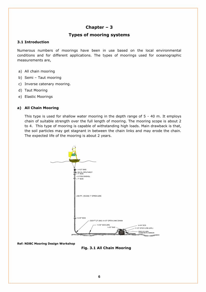
a) All Chain Mooring
This type is used for shallow water mooring in the depth range of 5 - 40 m. It employs
chain of suitable strength over the full length of mooring. The mooring scope is about 2
to 4. This type of mooring is capable of withstanding high loads. Main drawback is that,
the soil particles may get stagnant in between the chain links and may erode the chain.
The expected life of the mooring is about 2 years.
Ref: NDBC Mooring Design Workshop
Fig. 3.1 All Chain Mooring

7
b) Semi – Taut Mooring
This mooring employs chain at the bottom of the buoy and at the top of the anchor.
Nylon rope is used to complete the mooring in between the two chains. The nylon at the
middle of the mooring line gives compliance to the mooring and hence enables high load
carrying capacity. This can be used in depth range of 40 – 300 m and the mooring scope
is 1.5 – 2.5.
Ref: NDBC Mooring Design Workshop
Fig. 3.2 Semi – Taut Mooring
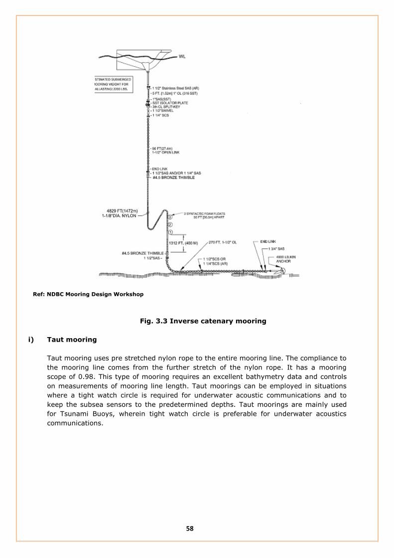
c) Inverse catenary mooring
Poly – nylon inverse catenary mooring consist of a nylon rope and polypropylene rope. It
can be employed to a depth of 2500 and more. The compliance comes from the ‘S’ shape
of the mooring along with the stretch of nylon and polypropylene ropes. Suspending
lower mooring with buoyant polypropylene line allows for access to deeper locations. This
type of mooring is capable of withstanding low to moderate loads based on the
properties of the mooring components and it has a mooring scope of about 1.1 – 1.3.

8
Ref: NDBC Mooring Design Workshop
Fig. 3.3 Inverse catenary mooring
d) Taut mooring
Taut mooring uses pre stretched nylon rope to the entire mooring line. The compliance to
the mooring line comes from the further stretch of the nylon rope. It has a mooring
scope of 0.98. This type of mooring requires an excellent bathymetry data and controls
on measurements of mooring line length. Taut moorings can be employed in situations
where a tight watch circle is required for underwater acoustic communications and to
keep the subsea sensors to the predetermined depths. Taut moorings are mainly used
for Tsunami Buoys, wherein tight watch circle is preferable for underwater acoustics
communications.

9
Ref: NDBC Mooring Design Workshop
Fig. 3.4 Taut Mooring
e) Elastic mooring
In this type the upper part of the mooring line consist of a length of rubber cord,
which will absorb the energy caused by the motion of the buoy and compensate for
the difference in water levels, tide, waves, etc. Elastic moorings can be effectively
used for shallow water moorings, wherein all chain mooring fails due to abrasion.

10
Chapter – 4
NIOT Buoy Description
4.1 Introduction
The discus shaped wave directional buoy equipped to measure wave, meteorology and
oceanographic parameters. The discus shaped buoy can be split in two halves to ease
assembly and transportation. A keel with counterweight is mounted under the hull to prevent
capsizing of the buoy. A cylinder in the middle of the buoy hull contains all electronic
modules, the power package and the wave sensors. The buoy mast is used to mount the
meteorological sensors and the antennas.
Fig. 4.1 Buoy Configuration

11
4.2 Description of the Buoy
The mechanical design objective is to have a strong but lightweight buoy. The materials are
polyethylene, aluminium and stainless steel. The shape, size and geometric aspects are given
by the dynamic response and stability requirements.
Fig. 4.2 Buoy Description

12
4.2.1 Buoy Materials
The hollow buoy hull is made up of Fibre Reinforced Plastics of thickens 5 mm. Isopthalic
resin is used in the formation of hull. Polyurethane foam of 64 kg/m3 is filled in the hollow
hull.
The Instrument container of the buoy is made up of marine grade aluminium and it is a
waterproof compartment to house the all electronics. At the bottom of the Instrument
container, keel weight and frame are attached and the mooring line continues from keel
Frame.
4.2.1 Buoy details
Reserve Buoyancy : 2100 kg
Diameter of the hull : 2.2 m
Total weight : 710 kg
Weight of keel : 110 kg
4.3 Stability and Dynamic Response
The wave directionality determination relies on the wave – following capability of the buoy
hull. The shape is in principle a discus, which is an excellent wave follower but is vulnerable
to capsizing. The design trade - off therefore lies between stability and dynamic response.
The buoy utilises a keel consisting of a heavy counterweight below the waterline. This
stabilises the buoy. To study the pitch and heave motion of the buoy under the action of
regular, random and double peak conditions a scaled down model is prepared and analysed
at the initial stage of the buoy design.

13
Chapter - 5
Globally Used Mooring Configurations
5.1 Introduction
Many different mooring configurations are in use at present globally to suit for different
applications and environmental conditions. This section describes the mooring configurations
adopted by different institutes or buoy operators for Met - Ocean and Tsunami Buoy
applications.
5.2 M/s Envirtech Italy
M/s.Envirtech is designed and developed many types of oceanographic buoys and moorings.
The description of the mooring design adopted by M/s Envirtech is as follows:
Type of Mooring : Inverse Catenary Mooring
Mooring Scope : 1.2
Ref. M/s Envirtech Systems, Italy.
Fig. 5.1 M/s Envirtech mooring Design

14
M/s Envirtech mooring system consist of two sections (i.e) Upper Section and Lower Section.
5.2.1 Upper Section
Upper section of the mooring consists of wire rope(Φ26mm) of 100m length and Polyester
rope of 800 m length. The polyester rope has a diameter of 42 mm and has a breaking
strength of 15.7ton.
5.2.2 Lower Section
This section has a polypropylene rope of length based on depth. The breaking strength of the
rope used is 16.92ton and has a diameter of 36 mm. As it has positive buoyant, it will float
and hence no rubbing will take place with the sea bed.
In addition with that, a deep sea buoy of 35 kg buoyancy is used to keep the lower section of
the mooring in upright position. Also it has a wire rope(Φ22mm) of 20 m length above the
anchor. This mooring design has a safety factor of 5.75. Deployment method used is buoy
first method.
5.2.3 Mooring rope length Calculation
The following length of ropes are used for a depth of 4200 m,
Wire rope(Φ26mm) = 100 m in the upper section. (Fixed length)
Polyester rope = 800 m in the upper section. (Fixed length)
Wire Rope = 20 m above the Anchor. (fixed length)
Polypropylene rope = (Scope x Depth) – 920 m
= 4030 m in the lower section.
5.2.4 Properties of the ropes
Polyester rope:
Nominal Diameter : 42 mm
Min. breaking strength : 15.70 T
Polypropylene rope
Nominal diameter : 42 mm
Min. breaking load : 16.90 T
Dead Weight
Mass : 4.0 T
Weight in water : 3.41 T
Anchor
Weight in air : 430 kg
Weight in water : 227kg

15
5.3 M/s SAIC, USA
Science Applications International Corporation (SAIC) USA is a pioneering organization in the
design of Tsunami buoys. The type of mooring used by the SAIC is Taut mooring and its
features are as follows:
Type of Mooring : Taut mooring
Mooring Scope : 0.98
Ref. M/s SAIC, USA
Fig. 5.2 SAIC Tsunami Buoy mooring design

16
This type of mooring system consists of two sections and is for Tsunami Buoys.
5.3.1 Upper Section
Upper Section consist of a Polypropylene Jacketed Wire rope and the details of which are,
Construction : 3 x 19, Low Rotation
Diameter : 11 mm
Length : 200 m
5.3.2 Lower Section
This section has an 8 – strand plaited nylon rope of 19 mm in diameter. Length of the rope
will be decided based on the depth at the location. The breaking strength of the nylon rope is
7.10 T. Nylon rope used here is pre-stretched to its working load limit.
5.3.4 Calculation of mooring ropes
Total Mooring length (TML) = (Scope x water Depth)
Length of nylon rope = TML – length of 7/8” Nylon rope (350 m) - length of
1” Nylon rope (250 m) - 213
The following length of ropes are used for a depth of 6000 m,
Total Mooring Length = 5880 m
Nylon Rope = 5067m
Wire rope = 200 m
Note: 213 m indicates the length of wire rope (200m) and the mooring hardwares (13m).
This type of mooring doesn’t have polypropylene rope and it requires an accurate survey on
bathymetry.
5.4 M/s First Institute of Oceanography (FIO), China
First Institute of Oceanography is a research institute engaged in applied and basic
oceanographic researches. The description of the mooring used by FIO is as follows:
Type of Mooring : Taut mooring
Mooring Scope : 0.98
Application : Met – Ocean Buoy
This type of mooring also has two sections.
5.4.1 Upper Section
This section consists of a Jacketed Wire rope, which in turn used as an Induction cable.
Details of the Induction cable is,
Construction : 3 x 19, Galvanized plow steel, Low Rotation type
Length : 700m
Minimum Breaking Strength : 6.71 T

17
5.4.2 Lower Section
This section has a Marine Grade yarn, of which details are,
Construction : 8 – strand, Plaited configuration
Maximum Stretch : 15 – 19 %
Stretching Load : 1.58 T for 2.5 Minutes
Breaking Load : 6.75 T
Note: This type of mooring doesn’t have polypropylene rope.
Ref. M/s RDSEA & Associates, INC, China
Fig. 5.3 M/s First Institute of Oceanography mooring design

18
5.5 M/s Fugro Oceanor, Norway (OMNI buoy mooring)
Fugro Oceanor is a Norway based oceanography organization that designs surface buoys and
mooring. Also it deploys large number of Buoy systems globally.
Type of Mooring : Inverse Catenary mooring
Scope : 1.22
Ref. M/s Fugro Oceanor, Norway
Fig. 5.4 OMNI Buoy mooring Design

19
OMNI buoy mooring design is for Met - Ocean Buoy and it has the following three sections.
5.5.1 Upper Section
Upper section has an Induction Cable of about 500 m length and the sub – surface sensors
are attached in it. The details of the induction cable are,
Diameter : 12 mm
Length : 500 m
5.5.2 Middle Section
Middle or compliance section has a Nylon rope and its details are,
Diameter : 18 mm
Construction : 12 strands, Plaited Construction
Length : 500m, depth below 2500 m
: 750 m, Depth above 2500 m
5.5.3 Lower Section
This section consists of a Polypropylene rope and an Anchor chain.
Diameter : 18 mm
Construction : 3 strands.
Length of chain : 2m, long – link
5.5.4 Mooring rope length calculation:
Length of Induction cable : 500m
Length of nylon rope : 500 m for depth less than 2500 m
: 750 m for depth greater than 2500 m
Calculation of Polypropylene rope length
From the figure,
cos θ = Depth /TML
TML = Depth /cos θ
Length of PP rope = TML – 500
Depth TML θ
θ
θ
θ
C
A B
NOTE:
TML – Total Mooring length
θ = 40° (for all moorings)

20
5.6 PMEL Mooring Design, USA
Pacific Marine Environmental Laboratory carries out interdisciplinary scientific investigations
in oceanography and atmospheric science. It maintains Tropical Ocean Atmospheric array
(TAO) in the Pacific Ocean, measuring and telemetering oceanographic and meteorological
data to the shore station. The mooring configurations used in the TAO mooring are,
Type of Mooring : Taut mooring
Mooring Scope : 0.985
Ref. M/s PMEL, USA
Fig. 5.5 TAO mooring Design

21
This type of mooring has two sections.
5.6.1 Upper Section
This section uses an Induction of following details
Construction : 3 x 19
Diameter : 9.5 mm
Length : 500 m
Minimum breaking strength : 6.30 T
5.6.2 Lower Section
Lower section consists of a Nylon rope of length depending on the deployment location.
Diameter : 19 mm
Construction : 8 strand plaited, Torque balanced type
5.6.3 Mooring Length Calculation
Depth = 4000 m
Total mooring length = 0.985 * Depth = 0.985 * 4000
= 3940 m
Length of Induction cable = 500 m
Length of mooring hardwares = 12 m
Length of nylon rope = 3940 – 500 -12
= 3428 m
A standard nylon rope length of 50 m is taken for deployment.
5.7 JAMSTEC Mooring Design
JAMSTEC uses two mooring systems based on the current at the deployment location.
Slack Mooring - High current
Taut Mooring - low current
5.7.1 Slack Mooring
Mooring scope : 1.2 – 1.3
This type of mooring has four sections.
5.7.1.1 Upper section
This section consists of a 1 m chain and a 520m wire rope. The details of the induction cable
are,
Construction : 7 x 7
Diameter : 10 mm
Breaking load : 6.56 T
Weight/ metre : 0.403 kg
Length : 520 m

22
Ref. M/s JAMSTEC, Japan
Fig. 5.6 Slack mooring Design
This section also consists of eight number of weight of 25 kg each. This is to keep the
Induction Cable in vertically downward. In between the weights, chains of 0.45 m length are
used.
5.7.1.2 Middle section
Compliance section consists of Nylon rope. The details of the nylon rope are,
Diameter : 17 mm
Construction : 12 strand, No Kink and No – rotation.
Breaking load : 7.13 T

23
5.7.1.3 Lower Section
This section consists of polypropylene rope and a chain of 4.54 m length, above the Sinker
Weight. The details of the Polypropylene rope are,
Diameter : 19 mm
Breaking load : 6.01 T
Construction : 12 strands.
5.7.1.4 Mooring length Calculation
In the slack mooring design of JAMSTEC, the ratio of nylon and polypropylene rope lengths
are 2:1. Hence, the length of nylon rope is twice of the polypropylene rope.
Mooring Rope Lengths
Depth : 4370 m
Length of Induction cable : 520 m
Length of Nylon Rope : 3600 m
Length of Polypropylene rope : 1,600 m
Total mooring length : 5720 m
NOTE: This mooring uses 4 No of swivels between the each sections. Also, use of Pair Ring
between the shackles is followed in this mooring.
5.7.2 Taut Mooring
Mooring Scope : 0.98 - 1
Taut mooring has two sections, details of which are given below:
5.7.2.1 Upper Section
This section has a wire rope only.
Construction : 1 x 37
Diameter : 16.3 mm
Tensile Grade of the Wire : 1770 N/mm2
Breaking Load : 10.2 T
Weight / metre : 0.641 kg
Length : 750 m
5.7.2.2 Lower Section
This section consists of a Nylon rope having the following properties:
Diameter : 17 mm
Construction : 12 strand, No Kink and No – rotation.
Breaking load : 7.13 T

24
Ref. M/s JAMSTEC, Japan
Fig. 5.7 Tight mooring Design
25
Chapter – 6
NIOT Mooring Configuration
6.1 Introduction
NIOT mooring design is broadly classified in to Shallow water mooring and Deep sea
mooring. Deep sea mooring is further classified into,
1) Met - Ocean Buoy Mooring
2) Tsunami Buoy Mooring
These two types of moorings are of Inverse catenary type, the difference is that selection of
rope lengths for different buoy systems. The commonalities between the two moorings are
elaborated as follows:
These two moorings are having three sections of different types of mooring ropes.
6.2 Upper section
The upper section of the mooring consists of a Tail chain and a Combination wire rope. Tail
chain of length 1.5 m is connected at the keel frame. Diameter of the chain is about 25.4 mm
and has a maximum Breaking load of 8500 kg.
The chain suffers from interlink wear as it absorbs a significant portion of the energy
generated by the buoy as it rises and falls following the surface movement of the sea. It also
has to absorb the rotational energy of the mooring induced by the buoy rotating around its
axis. To limit this effect a stabilizing fin can be fitted to the buoy on the opposite side to the
mooring eye. This fin also has the advantage of reducing the oscillation of the surface buoy in
flowing water.
The combination wire rope is of 6 x 19 construction and has a diameter of 18 mm. It has a
maximum breaking load of 9000 kg and its length is 550m.This section is designed to protect
the mooring from fish bite and to enable the safe deployment and retrieval of the buoys.
The important aspect to be considered in the selection of construction of the combination
wire rope is rotating or non-rotating type. In the mooring it is necessary to have a non-
rotating type of ropes, to avoid the effect of untwisting of the rope. From the literatures, it
came to know that, 6 x 19 construction is not a non – rotating type and hence it is not
advisable for Buoy moorings.
6.3 Middle section
This section has a Nylon rope of 16 mm diameter and 12 strands. This section gives S –
shape to the mooring. During high current, the nylon rope stretches and keeps the buoy
always surfaced. The length of the nylon rope is chosen carefully to provide sufficient stretch
to the mooring line. The maximum breaking load of the nylon rope is 5500 kg and it can
stretch to about 20% of its initial length when stretched to its working load limit.

26
NS
IT
NO
T
I
IA
L
OCETE OUT
F
CH
NE
T
NIA
Y
G
OO
L
C EH
NA
N
AN
Fig. 6.1 NIOT Mooring Design
6.4 Lower section
The lower section of the mooring consists of a Polypropylene rope and a ground chain. The
polypropylene rope is of 18 mm in diameter and has a working load limit of 5500 kg. The
length of the polypropylene rope is total depth minus the length of the combination wire
rope. The polypropylene rope can stretch upto 15% of its original length.
The ground chain is a 3m length and 25.4 mm in diameter. It connects the polypropylene
rope with the sinker weight of 2000 kg. In order to avoid the rubbing of chain with the sinker
weight, subsurface floats are added in the mooring line which keeps the chain in upright
position.
The sinker weight and the drag Anchor of the mooring keeps the buoy in its position.
6.5 Calculation of Mooring Rope Lengths
The length of Combination wire rope and nylon rope are fixed and are 550m and 320 m
respectively. Polypropylene rope (PP) length is calculated as follows:
6.5.1 Met - Ocean Buoy
Total Mooring length = Scope x water depth
Length of PP rope = Total mooring length – 550 – 320 – 6
NIOT maintains the mooring scope in the range of 1.2 – 1.3 for Met – Ocean Buoys.

27
6.5.2 Tsunami Buoy
The figure below shows the typical Mooring drawing for tsunami Buoy system.
Fig. 6.2 Tsunami Buoy Mooring Drawing
In the case of Tsunami buoy it is mandatory to have a tight watch circle to facilitate the
effective underwater communication between the Bottom Pressure Recorder (BPR) and
Surface Modem attached. The surface modem attached in the top of the mooring line
communicates with the BPR placed at the sea bottom. It is required to keep the surface
modem in the area of the Acoustic cone of the BPR. The schematic representation of the
Buoy watch Circle and the circle formed by the Acoustic cone of the BPR at the sea surface is
shown in the figure 6.2.

28
Fig. 6.3 Tsunami Buoy watch Circle
The ways of achieving this close watch circle is to deploy
The BPR very close to the buoy anchor
By limiting the mooring scope.
In the first option, the BPR is deployed very close to the Anchor Settled point. From the
experiences gained in the Tsunami Buoy deployment, the optimum distance between the
Anchor and the BPR is 200 to 300 m.
In the tsunami buoy mooring configuration, a mooring of scope in the range of 1.04 to 1.08
is maintained to have a tight watch circle radius. The length of the mooring ropes area as
follows:
Total Mooring length = Scope x water depth
Length of PP rope = Total mooring length – 550 – 160 – 6*
*Total length of the mooring hardware is 6 m.
6.6 Sub – surface floats
Sub – surface floats are attached in between the nylon and polypropylene ropes to keep the
lower section in upright position. As the polypropylene rope is positive buoyant it will float
and the based on the weight of chain in sea water, the required buoyancy of the sub –
surface floats were calculated. In the present mooring, six numbers of 7 kg buoyancy sub-
surface floats are used.

29
6.7 Swivel
Swivels are used in the mooring lines to relieve the twist and torque that builds up ion the
mooring line. The swivel is often placed between the section of chain and Combination wire
rope.
6.8 Connecting link
Connecting link is used in the locations where, the connection point of the two pieces of
different ropes. It may avoid the rubbing of ropes.
6.9 Sinker weight
The sinker usually provides the attachment of the mooring to the seabed. It has the
advantage that, it can resist the load from all directions. In addition with sinkers, an anchor
is used if the mooring load is always in one direction. An anchor can provide considerably
more resistance than a sinker of the same, when it is correctly buried in the sea.
6.10 Anchor
The anchor provided with the sinker weight, penetrate into the seabed, either partially or
fully and thus avoiding the horizontal movement of sinker weight.
6.11 Swinging Radius or Watch Circle Radius
It is the radius of the circular movement of the buoy about its anchored point. It has its own
significance in the case of Tsunami buoys, wherein tight watch circle is required for effective
underwater communication between the surface Modem and the Bottom Pressure recorder.
Also, by the use of watch circle radius, one can decide whether the buoy is in anchored
position or not.
6.12 Deployment procedures
Deep-ocean surface moorings are typically deployed using an anchor-last technique. As the
name implies, the anchor is the last component to be deployed. The entire mooring, starting
at the top (from buoy), is put over the side and strung out behind the deployment vessel and
towed into position. At the appropriate location the anchor is dropped. The sequences of
operations are illustrated as follows:

30
Fig. 6.4 Buoy deployment procedures
Deploying additional
upper instruments
Stopped off on deck
Start of
buoy deployment
Quick-release
hook
Buoy outboard of ship
ready to be lowered
Quick-release hook
Buoy released and in
tow from mooring
winch on deck
Glass ball buoyancy attached
Anchor away
Initial instrument deployment
Stopped off on deck

31
6.13 NIOT Shallow Water Mooring Design
The most common form of shallow water mooring line material is steel chain. The chain may
form a catenary between the buoy and the seabed and will be able to absorb considerable
amounts of energy. With the correct equipment it is easy and safe to handle. Chain can
easily be joined with shackles with little reduction in its tensile strength.
Shallow water mooring having conventional chain as mooring line deployed in the location
were breaking waves are encountered may also be problematic. If breaking waves regularly
occur at the buoy site, it will impart considerable energy to the buoy. The mooring chain
may not be able to absorb the very high loads generated by the wave, resulting in the chain
being broken or the sinker dragging from position. Also, because of the rubbing of chain with
seabed, sand particles may accumulate on the gap between the chain, and lead to erosion.
One solution to the problem is the use of wire rope or synthetic ropes.
Shallow water mooring deployed by NIOT, uses a total mooring length of 1.5 – 2 times the
depth at the deployment location. The full mooring consists of Combination wire rope.
O
E
I T
NA
HC
LN
AO
UTIT
IS
N
ET
CO
YG
INN A
LH
ON
EA
C
NET
F O
6.5 Shallow water mooring design (RP 02 buoy)
The required numbers of sub-surface floats were calculated to make a part of the mooring
afloat. It enables the easy swapping of surface buoy for maintenance activities.
32
Chapter – 7
Mooring Components
7.1 Introduction
A typical mooring system can be divided in three different components, the mooring line, the
connectors and the Anchor point. This section describes the type, materials and properties of
the commonly used mooring Components.
7.2 Mooring line
7.2.1 Chain
The most common product used for mooring lines is chain which is different diameters and
grades. Two different designs of chain are used frequently, studlink and studless chain. The
studlink chain is most commonly used for moorings that have to be reset numerous during
their lifetime. Studless link chain is often used for moorings of Floating production Units and
buoys. It can be easily connected by using shackles.
7.2.1 Combination wire Rope
Combination wire ropes have a lower weight than chain, for the same breaking load.
Common wire ropes used in oceanographic mooring are of 3 x 19 construction, which is
non – rotating rope. Wire rope is terminated with thimbles for connection to the other
components in the mooring system. To avoid the corrosion of wire rope, polypropylene
sheathing is provided.
7.2.2 Synthetic fibre rope
Synthetic fibre ropes are used in mooring lines to provide the compliance to the mooring.
Typical materials that can be used are polyester and high modulus polyethylene. The major
advantage of the fibre ropes is the light weight of the material and its positive buoyancy in
case of polyethylene ropes.
7.3 Connectors
7.3.1 Shackles
The shackle is a connector that is very common in the offshore moorings. It consists of a
bow, which is closed by a pin and locked by cotter pin. Many different types of shackles are
available depending on the application.
7.3.2 Connecting link
Connecting link is used in the locations where, the connection point of the two pieces of
different ropes. It may avoid the rubbing of ropes.
7.3.3 Swivel
Swivels are used in the mooring lines to relieve the twist and torque that builds up ion the
mooring line. The swivel is often placed between the section of chain and Combination wire
rope.

33
7.4 Selection of mooring components
Selection of components for oceanographic mooring is very important. Particularly the
selected component must have high specific strength to reduce the self weight of the
mooring without sacrificing the strength.
The points to be considered when selecting the mooring rope and mooring hardwares are,
a) Rope Construction
b) End terminations
c) Types of fibres
d) Specific Strength
e) Shape and dimensions
f) Resistance to Corrosion
g) Fatigue strength
a) Rope Construction
Single point moored systems are essentially having one – free end. During deployment, the
heavy anchor is free to turn, causing the wires or the strands to rotate and the strand or the
rope to unlay and open up. This action can be very detrimental to the line, and may result in
the split of the jacket material, in the reduction of the strength and in the formation of kinks.
Non rotating ropes can be designed in such a way that the tendency for the strands to rotate
in one way is balanced by the tendency for the wires in the strands to rotate the other way.
Exact rotation characteristics of wire ropes must be established experimentally. Wire ropes
with strong rotation tendencies (6 x 19, 7 x 25) are doomed to failure when used as deep –
sea mooring lines.
Wire ropes having 3 x 19 construction is deemed as non rotating type and can be widely
used in oceanographic deep sea mooring applications.
Fig. 7.1 3 x 19 construction
A great variety of ropes are available with many different fibre types as well as types of
construction. The use of natural fibre ropes for load carrying applications has almost
disappeared. Natural fibre ropes have low strength, will have a short life when compared with
synthetic fibres and are no longer cheaper than their synthetic counterparts.
Traditional 3-strand rope construction has also largely been superseded by plaited or braided
constructions where high strength and long life are the primary requirements.
Fig.7.2 3 – strand Construction

34
This is the oldest and simplest rope construction, consisting of 3 twisted strands laid
together. Three strand ropes are hard wearing and easily spliced.
Multiplait rope consists of 8 strands plaited in pairs, each pair passing over one pair and
under the next. It is easily spliced and the twisted strands offer good resistance to abrasion.
Fig.7.3 Multiplait Construction
b) Rope terminations
Wire rope is terminated with thimbles for connection to the other mooring in the mooring
system.
I. Thimbles
The use of wire rope has lead to the development of thimbles which allow ropes carrying
very high loads to be shackled to other mooring hardwares without damaging the ropes.
The common end terminations and its strength compared with the parent materials are
shown in the figure.
Fig.7.4 Strength of End terminations
II. Splices
The modern rope constructions (i.e. braided and plaited) allow high strength splices to be
made when the rope has been installed around the thimble. It should be noted that, the
detailed splicing information must be obtained from the rope manufacturer and that these
instructions have to be followed precisely in order to retain the majority of the rope
strength at the splice.

35
Mooring calculations must take into account the reduction of strength resulting from the
splices, usually on the order of 10% for correctly made splices.
c) Types of fibres
Ropes made of synthetic fiber are often used as buoy system anchoring lines. These ropes
do not corrode nor deteriorate appreciably in sea water. Their strength to immersed
weight ratio is excellent. The common materials used in the manufacture of synthetic
fibers,
I. Nylon
This provides high strength, elastic rope with good shock absorbing qualities. However
some ultimate strength is lost due to water abrasion if the rope is permanently immersed
in water.
II. Polyester
This is widely used to construct high strength, low stretch ropes with good wear
resistance and long life. Their strength is somewhat less than the strength of the nylon
when dry, but it does not change appreciably when wet. Their endurance is very good,
and their resistance to abrasion and chemicals are excellent.
III. Polypropylene
This has been used for cheap, general purpose rope which floats. However recent
developments in fibre manufacture and rope construction have resulted in moderate
performance ropes, which are considerably less expensive than nylon or polyester ropes.
IV. Advanced fibres
These include Aramid fibres (trade name Kevlar) and high modulus polyethylene (trade
names Spectra, Dyneema, and Vectran) which have very high strengths associated with
very low stretch. These ropes are also buoyant. However these are very expensive
products being approximately three times the cost of nylon or polypropylene.
d) Shape, Dimensions and Specific Strength
In the design of oceanographic buoy moorings, it is necessary to use ideal shaped and
less dimensioned materials to reduce the forces caused due to drag. Specific weight of
the mooring hardwares is defined as the strength per unit weight of the components.
Hardwares made up of different materials and sizes have higher specific strength then
the one made up of low grade materials. Low grade materials have more weight and
dimension which in turn increases the self weight of the mooring and the mooring force
due to drag.
e) Resistance to corrosion and wear
Rust, electrolytic action and pollution may reduce the normal life of a mooring line. Rust,
which is due to oxidation, occurs both ashore and at sea. Electrolytic action results from a
potential difference between components of a mooring. This is caused by using dissimilar
metals in the same mooring immersed in a common electrolyte, in this case water. It

36
shows as pitting near and in the welds of chain links and in the chain each side of
connecting shackles, over a length, of about 1-2 metres. Electrolytic action can be
significantly reduced by making the buoy body and all the metallic components of the
mooring from the same or very similar grades of steel. Polluted waters also have an
influence on the extent of pitting corrosion. It is mainly observed in the riding part of the
mooring chain.
Wear
The extent to which wear occurs mainly depends on the quality of the materials from
which the mooring is made. Wear is also affected by local environmental conditions, in
particular:
Type of seabed
Amount of sand transport in the water
Depth of water
Weather conditions.
The mooring cannot change these conditions but can only react to them.
A reduction in bar diameter will be observed at the contact point of the links. This may be
due to wear resulting from the movement between links or to local deformation of the
metal caused by impact loads due to the chain ‘snatching’. Snatching can also cause
elongation of the links.
In an area where the seabed is sandy and in particular during bad weather or in strong
tidal currents, a heavy sand transport can be expected. This will cause severe abrasion of
the mooring components. The thrash section of the mooring has the most pronounced
wear as it is continuously moving. Even in waters with small tidal range, where only a
small part of the mooring chain moves over the sea bed, very significant wear may be
found. It is common practice to use a larger size chain for the thrash area to account for
this extra wear.
f) Fatigue Strength
In the marine environment, all the components are subjected to fatigue loading; hence it
is mandatory to have a component having high fatigue strength. For the marine
applications it is broadly accepted by the standards, that the specimen should be tested
for 20,000 cycles at its working load limit.
37
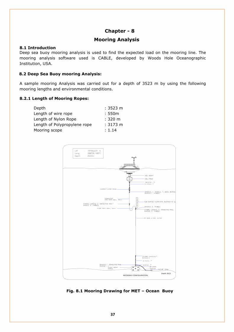
Chapter - 8
Mooring Analysis
8.1 Introduction
Deep sea buoy mooring analysis is used to find the expected load on the mooring line. The
mooring analysis software used is CABLE, developed by Woods Hole Oceanographic
Institution, USA.
8.2 Deep Sea Buoy mooring Analysis:
A sample mooring Analysis was carried out for a depth of 3523 m by using the following
mooring lengths and environmental conditions.
8.2.1 Length of Mooring Ropes:
Depth : 3523 m
Length of wire rope : 550m
Length of Nylon Rope : 320 m
Length of Polypropylene rope : 3173 m
Mooring scope : 1.14
MOORING CONFIGURATION
Depth 3523
Fig. 8.1 Mooring Drawing for MET – Ocean Buoy

38
Environmental Parameters:
The environmental parameters used in the analysis are,
Surface Current Speed = 2 m/s
At 100 m Depth = 1 m/s
At 1000m Depth = 0.5 m/s
At 3500 m/s = 0.1 m/s
Maximum Wave height = 12.5 m
Wave Period = 10.5 s
Results:
The results of the analysis are,
Buoy Draft = 0.737 m
Maximum Tension = 3027.45 N at the depth of 1.96785m (Chain part above the Anchor)
Minimum Tension = 2852.96 N at the depth of 2675.58164 (At the part of Nylon Rope)
Tension below the Buoy = 3016 N (At the chain part below the buoy)
Table 1. Results of the Mooring Analysis
S.NO Tension (N) Breaking Strength
(N) Remarks
1. 3027.45 78, 480 (GI chain) This is the maximum tension experienced in the
mooring line. It can occur at the part of chain
above the anchor.
2. 2852.96 53,955 (Nylon Rope) This is the minimum tension experienced in the
mooring line. It can occur at the part of Nylon
Rope.
3. 3016.59 78, 480 (GI chain) Tension at the chain below the buoy
4. 2950.186 53,955 (PP Rope) Tension at the PP rope line
39
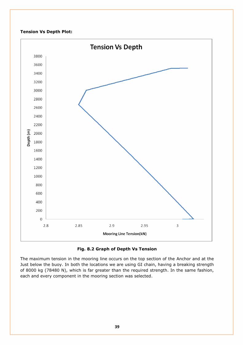
Tension Vs Depth Plot:
Fig. 8.2 Graph of Depth Vs Tension
The maximum tension in the mooring line occurs on the top section of the Anchor and at the
Just below the buoy. In both the locations we are using GI chain, having a breaking strength
of 8000 kg (78480 N), which is far greater than the required strength. In the same fashion,
each and every component in the mooring section was selected.

40
ii. Shallow Water Mooring Analysis
This section describes the mooring analysis carried out for shallow water mooring
deployed at Andaman.
Depth : 10m
Length of wire rope : 10 m
Length of chain : 1 m below the buoy
: 1m above the anchor
Scope : 1.5 - 2
Fig. 8.3 Mooring Drawing for RP 01 Buoy
Environmental parameters:
Current Speed = 2m/s
Wind speed = 6.5 m/s
Wave height = 12.5 m

41
Results of the Analysis:
From the analysis it is observed that the maximum load acting on the wire rope is about
6 kN (0.61 ton, minimum breaking load is 9 tonnes) and only negligible amount of sinker
movement may take place.
Fig. 8.4 Depth Vs Tension
Comparison of CABLE and Orcaflex Results:
S.No Parameter CABLE Results ORCAFLEX Results % variation
1. Tension on
Mooring 5.7 KN 6 KN 5
As a result, from the analysis it is observed that the maximum load acting on the mooring is
about 5.7 kN (0.57 ton, Minimum breaking load is 9 tonnes) and only negligible amount of
movement of sinker weight only will take place (1.07 m).
The obtained result from the CABLE software is having a deviation of about 5 % only.

42
Annexure: 1 Specification:
This section describes the specifications of the mooring ropes and hardwares presently in use
at NIOT.
COMBINATION WIRE ROPE:
Strand Construction : 6 x 19 + Independent Wire Rope Core (IWRC)
Sheathing : Each strand of the rope except IWRC shall be
Sheathed with polypropylene.
Type of lay : Right hand Ordinary Lay
Nominal diameter : 18 mm
Minimum Breaking Load : 9 tons
Tensile grade of wire : 1770 N/ mm2.
Galvanization : Wires shall be type “A” galvanized,
as per IS 1835/Equivalent
Lubrication : Medium duty marine application
Length of the rope : 550 m per spool
NYLON ROPE:
Nominal diameter of the rope : 16 mm
Minimum breaking load : 5.5 tons
Specific gravity : Around 1.14
Melting Point : 260° C.
Length of the rope : 320m per spool
Water absorption : max 4%
Breaking Elongation : 21%

43
Load Vs Elongation curve for Nylon Rope:
Ref: M/s D.Koronakis, Greece
POLYPROPYLENE ROPE
Nominal diameter of the rope : 18 mm
Minimum breaking load : 5.5 tons
Specific gravity : 0.99
Melting Point : 260° C
Water absorption : 1%
Breaking Elongation : 12-14%
LOAD-ELONGATION CURVE
USED KAPANYLON
0
10
20
30
40
50
60
70
80
90
100
0 5 10 15 20 25 30
ELOGATION (%)
TE
NS
ILE
ST
RE
NG
TH
(%
)
44
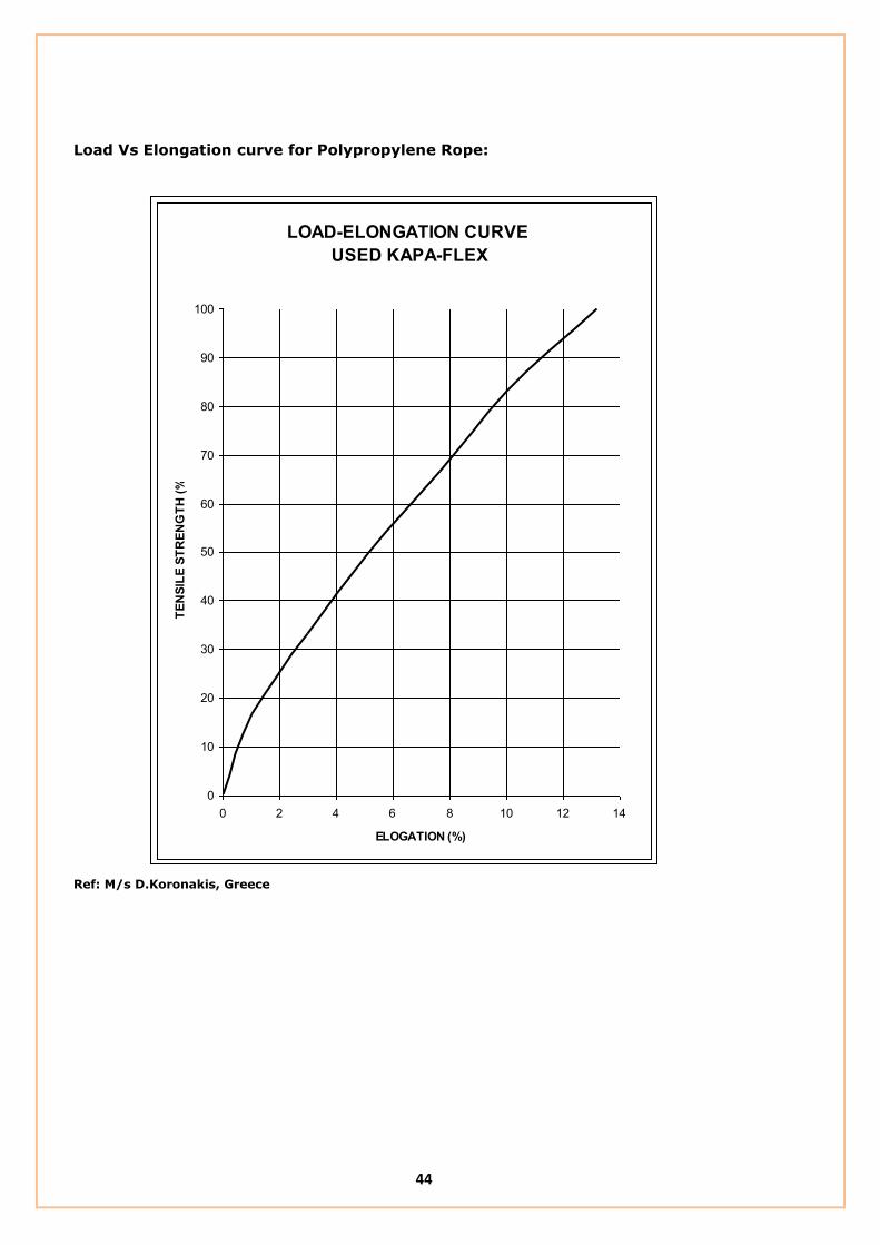
Load Vs Elongation curve for Polypropylene Rope:
Ref: M/s D.Koronakis, Greece
LOAD-ELONGATION CURVE
USED KAPA-FLEX
0
10
20
30
40
50
60
70
80
90
100
0 2 4 6 8 10 12 14
ELOGATION (%)
TE
NS
ILE
ST
RE
NG
TH
(%
)

45
MOORING HARDWARES:
Sl.no Item description Material Size
Maximum
Breaking Load
(Tonnes)
1 G.I.Bow shackle Carbon steel 1”/25.4mm 8.5
2 G.I. chain (short
link)
Carbon steel 1”/25.4mm 8.5
3 Swivel Carbon steel 1”/25.4mm 8.5
4 Pear ring or
Connecting ring
Carbon steel 1”/25.4mm 8.5
5 Open type G.I.
thimble
Steel To suit 18 mm
rope ----
Need
The performance of presently used mooring systems showed mixed experience. There are
cases wherein mooring deployed by NIOT remained in position for few years. However recent
years, technological developments have taken place in materials, construction and
specification of mooring components used and mooring analysis is also improved. Hence
there is a need to re-look into the present design and recommend newer design and new
material could be adopted form the experience of similar mooring systems being used
globally.
In spite of the success of the present moorings, the followings points need to be addressed:
It is recommended by the Nylon rope manufacturer to reconsider the use of Rotating
type of Combination Wire rope with the Non – rotating type of Nylon and
Polypropylene rope.
Optimization of mooring rope lengths for different buoy systems to suite for different
operating conditions.
Improvising the specifications of Mooring ropes and hardwares in par with different
materials used by other organizations and recent advancements in the offshore
mooring Technology.
Complete mooring system should be supplied and certified by a single supplier.

46
Suggested points
S.No Specification of existing Components Suggested Modification Remarks
1 WIRE ROPE JACKETED WIRE ROPE
Construction : 6 x 19 + IWRC Construction : 3 x 19
Sheathing : Each strand of the rope except IWRC. Sheathing : Polypropylene Jacketed.
Type of lay : Right hand Ordinary Lay, Rotational type Type of lay : Torque Balanced
Diameter : 18 mm Diameter : 11 mm
Minimum Breaking Load : 9 tons Minimum Breaking Load :9 tons
Tensile grade of wire : 1770 N/ mm2 Tensile grade of wire :1770 N/ mm2
Length of the rope : 550 m per spool Length of the rope : 550 m per spool
Make : M/s Bharat Wire Ropes, India Make : M/s Mooring Systems INC, USA
: M/S Seaproof Solutions, Norway
: M/s Loos and Co, USA
2 NYLON ROPE NYLON ROPE
Construction : 12 strand, Plaited
Construction : 12 strand, braided : 8 strand, plaited
Nominal diameter of the rope: 16 mm Nominal diameter of the rope :16 mm, 18 mm
Minimum breaking load : 5.5 tons Minimum breaking load : 7.8 tons
Length of the rope :320m for Met - Ocean Buoy Length of the rope :320m for Met - Ocean Buoy
: 160 m for Tsunami Buoy : 160 m for Tsunami Buoy
Breaking Elongation : 21 % Breaking Elongation : 21 %
Make : M/s D. Koronakis. S.A, Greece Make : M/s D. Koronakis. S.A, Greece
: M/s Columbian Speciality products
Division of Plymkraft, INC
: M/s Yale Cordage
: M/s Erling Haug, Norway
3 POLYPROPYLENE ROPE POLYPROPYLENE ROPE
Construction :12 strand, Construction :12 strand,
Nominal diameter of the rope :18 mm : 3 Strand Nominal diameter of the rope :18 mm
Minimum breaking load :5.5 tons Minimum breaking load :5.5 tons
Length of the rope :2000 m, 1000 m Length of the rope :2000 m, 1000 m
Breaking Elongation : 12 % Breaking Elongation : 12 %
Make : M/s D. Koronakis. S.A, Greece Make : M/s D. Koronakis. S.A, Greece
: M/s Erling Haug, Norway
4 Shackles
Type : Bow Shackle, Bolt and Nut Type. Type : Bow Shackle, Bolt and Nut Type.
Dimension : 1", 3/4" Dimension: 3/4", 5/8"
Material : carbon steel Material : Alloy steel
Working Load Limit : 8.5 tonnes and 4.75 tonnes Breaking Load : 4.75 tonnes and 3.25 tonnes
Should be Fatigue tested
Make : M/s Sealinkers PVT Ltd, India Make : M/s Grossby Group, USA
: M/s Gunnebo, Norway

47
S.No Specification of existing Components Suggested Modification Remarks
5 Chain
Type : Short Link GI chain Type : Long Link GI chain
Dimension: 1" Dimension: 3/4",
Material : carbon steel Material : Alloy steel
Working Load Limit : 8.5 tonnes Breaking Load : 4.75 tones
Should be Fatigue tested
Make: M/s Grossby Group, USA
: M/s Gunnebo, Norway
6 Bearing Swivel
Type : Eye & Eye Type : Eye & Eye
Working Load Limit : 5.5 tonnes Working Load Limit : 5.5 tonnes
Should be Fatigue tested
Make : M/s Sealinkers PVT Ltd, India Make : M/s Grossby group, USA
: M/s M/s Gunnebo, Norway
7 Thimble
Type : open type GI Thimble Type: Polyeurethane Thimble
8 Connecting Ring
Type : Oblong Master Link Type : Oblong Master Link
Diameter : 19 mm Working Load Limit : 5.4 tonnes
Working Load Limit : 5.4 tonnes Should be Fatigue tested
Make : M/s Sealinkers PVT Ltd, India Make : M/s Grossby group, USA
: M/s M/s Gunnebo, Norway
9 Sinker weight
Weight : 2 tonnes Weight : 2 tonnes
Shape : Cube Shape : Cylindrical
Make: M/s Express engineering, India Make: M/s Express engineering, India
10 Anchor:
Weight : 130 kg Weight : 130 kg
Type : Denforth Anchor Type : Denforth Anchor
Make: M/s Eurotech Systems, India Make: M/s Eurotech Systems, India

48
Annexure: 2 List of Buoy Deployment locations:
Bay of Bengal Arabian Sea
Met Ocean Buoy
Buoy
Location
Latitude
(N)
Longitude
(E)
Depth(m) Buoy
Location
Latitude
(N)
Longitude
(E)
Depth(m)
BD01 18°49’ 00” 89°00’ 00” 2110 AD01 19° 00’ 00” 67° 00’ 00” 3210
BD02 18°30’ 00” 88°00’ 00” 2176 AD02 15° 00’ 00” 69° 00’ 00” 3867
BD03 15° 30’ 00” 90° 00’ 00” 2648 AD03 12° 00’ 00” 69°00’ 00” 4173
BD04 14°12’ 00” 82°54’ 00” 3369 AD04 08° 00’ 00” 73° 00’ 00” 2250
BD05 10° 30’ 00” 94° 00’ 00” 3149 AD05 06°30’ 00” 68°50’ 00” 2002
BD06 10° 00’ 00” 88° 30’ 00” 3432 SW02 17°21’ 06” 70°42’ 08” 2220
BD07 06°15’ 00” 85°53’ 00” 3870 RP02 10°52’ 55” 72°12’ 68” 20
NIOT Tsunami Buoy & SAIC Buoy
TB05 11° 00’ 00” 89° 30’ 00” 3210 TB12 21° 24’ 00” 64° 06’ 00” 2552
TB06 15° 00’ 00” 90° 00’ 00” 2736 STB02 20° 48’ 00” 65° 20’ 25”
TB08 12° 30’ 00” 85° 30’ 00” 3285 TB10 06°54’ 00” 86°59’ 00” 3860

49
Annexure : 3 Suite of sensors
The table below describes the list of Met – Ocean buoy sensors and its make.
SL.NO SENSOR MAKE OF THE SENSOR
1 Wind LAMBRECHT
R M YOUNG
2 Humidity/Air Temperature ROTRONICS
3 Air Pressure VAISALA
4 Wave Measurement SEATEX MRU
5 Conductivity AND Temperature VALEPORT,ALLEC, SEABIRD
6 Satellite Transceiver T&T /INMARSAT
7 Precipitation R M YOUNG
8 Radiation Sensor EPPLY LAB
9 Compass KVH

50
References
1. R.Balaji, S.A.sannasiraj and V.sundar, “ Physical model studies on discus buoy in
regular, random, and double peak spectral waves”, Indian Journal of Marine sciences,
Vol. 36(1), March 2007, pp. 18 – 26
2. R. P. Trask and R. A. Weller, “Moorings” Woods Hole Oceanographic Institution
technical report.
3. NIOT Buoy Manual and standard operating procedures.
4. Buoy Engineering by Henri O. Berteaux, Willey Sons 1978
5. IALA design Guidelines for Offshore Moorings.
6. http://www.envirtech.com/index.html
7. http://www.saic.com/about
8. http://www.fio.org.cn/english/index.asp
9. http://www.oceanor.no
10. http://www.pmel.noaa.gov

51
DESIGN OF MOORING SYSTEM
FOR
MET - OCEAN AND TSUNAMI DATA COLLECTION
OCEAN OBSERVATION SYSTEMS
NATIONAL INSTITUTE OF OCEAN TECHNOLOGY
[Ministry of Earth Sciences, Government of India]
PALLIKARANAI, CHENNAI – 600 100
INDIA
FEBRUARY 2012

52
Chapter – 1
Introduction
The need to measure ocean surface and sub surface parameters in the water column for
extended periods to better understand ocean dynamics was a driving force that led to the
development of oceanographic moorings. Today’s moorings are used as ‘platforms’ from
which a variety of measurements can be made. These include not only the speed and
direction of currents, but also other physical parameters, such as conductivity (salinity),
temperature, as well as surface meteorology parameters.
Mooring is a compliant section between the surface buoy and the sinker weight, which
restraints buoys against the action of wind, wave and current forces. Moorings typically have
three basic components: an anchor, some type of chain or line to which instrumentation can
be attached, and flotation devices that keep the line and instrumentation from falling to the
sea bed. Shackles and links are typically used to connect mooring components and to secure
instruments in line. The choice of hardware, mooring line and flotation for a particular
application, as well as the size and design of the anchor, depends on the type of mooring and
the environment in which it is deployed.
Mooring is the most important aspect of any buoy program as it secures the floating platform
which houses the sensible and expensive sensors. Mooring design, that is the art of properly
selecting size, materials, shape, configuration, etc. of buoy system components has also
made great progress, often obtained by trial and error methods in olden days and by using
advanced software packages at present. The numerous mooring configurations have been
evolved to suit for different geographical locations under specified environmental conditions.
The general considerations in the design of moorings are,
The depth at the Deployment Location
Buoyancy of the surface float to be used
Sea bed conditions at the site such as Topography and soil conditions
The loads imposed on the mooring by the surface buoy due to the action of wind,
wave and current.
Expected loads on the mooring.
Required life of the mooring and the servicing facilities available.
Local conditions that cause wear and corrosion of the mooring components.
Deployment procedure.
Expected scope of the mooring (i.e.) mooring scope is the ratio between the total
mooring length to the depth at the deployment location.
53
Chapter - 2
Literature Survey
Oceanographic moorings fall into two broad categories surface and subsurface. The difference
between the two is that the surface mooring has a buoy floating on the ocean surface,
whereas the subsurface mooring does not. Although the two mooring types have similar
components, the capabilities of the two are very different. With a surface buoy, it is possible
to measure surface meteorology, real time data transmission and make very near surface
measurements in the upper ocean. The surface mooring, however, is exposed to ocean
storms with high wind and wave conditions and therefore must be constructed to withstand
the forces associated with the wind and waves. In addition, it may transmit some unwanted
motion to subsurface instruments if care is not taken. The subsurface mooring, on the other
hand, is away from the surface forcing and can be fabricated from smaller, lighter
components, which are less expensive and easier to handle. However, it is difficult to make
near-surface measurements from a subsurface mooring.
Growing interest in understanding interactions between the ocean and the atmosphere has
led to the development of surface moorings. The surface mooring is a unique structure. It
extends from above the surface to the ocean bottom, providing a platform from which both
meteorological and oceanographic measurements can be made in waters that range from
shallow to full ocean depth. Surface-mooring designs must consider the effects of surface
waves, ocean currents, bio-fouling, and other factors that can vary with the time, location,
regional climate and weather patterns. The success of the surface-mooring deployment often
depends on the abilities both to accurately estimate the range of conditions that the mooring
may encounter while deployed and to design a structure that will survive those conditions.
The primary goal of any mooring deployment is to keep the mooring on location and making
accurate measurements. Adverse environmental conditions not only influence the longevity
itself but also impact the instruments that the mooring supports.
Surface moorings are used to support both the meteorological and sub-surface
oceanographic instruments from very close to the surface to near the bottom. Measurements
of physical properties, such as temperature, speed, and conductivity (salinity), as well as of
biological parameters, such as photo synthetically available radiation (PAR) are routinely
made from surface moorings. The surface buoy provides a platform from which
meteorological measurements can be made and a structure from which both surface and
sub-surface collected data can be transmitted via satellite. Meteorological sensors typically
deployed on a surface buoy measures wind speed, wind direction, air temperature, relative
humidity, barometric pressure, precipitation, and long-wave and short-wave radiation. The
meteorological data are stored in the memory of the sensor and transmitted via satellite to a
receiving station ashore. The transmitted data often play an important part in real-time
analysis and reaction to conditions on site. The data can also be passed to weather centres
for forecasting purposes.
Early moorings consisted of a surface float, surplus railroad wheels as an anchor, and
lightweight synthetic line, such as polypropylene or nylon, to connect the surface float to the
anchor. Several kilometres of line are required for a full-depth ocean mooring.

54
Studies showed that the synthetic ropes were being damaged by fish bite. Analysis of many
failed lines revealed tooth fragments and bite patterns that were used to identify the type of
fish responsible for the damage. Statistics concerning the number of fish bites, their depths,
and their locations were collected, and it was found that the majority of fish bites occurred in
the upper ocean depth up to 600 m. Prevention of mooring failure due to fish attack required
lines that could resist fish bite.
Ropes made of high-strength steel wires were an obvious candidate. Combination wire rope
would not only provide protection from fish bite, but also would have minimal stretch, unlike
the synthetic ropes, and would provide high strength with relatively low drag. Many types of
wire rope construction and sizes were tested, in addition to methods for terminating the wire
rope; terminations are the fittings attached to the ends of wire sections. A desirable
termination is one that is as strong as the wire rope itself. If the technique used to terminate
a rope imposes stress concentrations, which significantly reduce the strength of the wire rope,
then the whole system is weakened. Methods of terminating wire include the formation of
eyes into which shackles can be attached either from swaged fittings or from resin-poured
sockets. Swaged terminations utilize a fitting that is slid onto the end of the wire and pressed
or swaged onto the wire with a hydraulic press.
At present, galvanized 3 x 19 wire rope is widely used for oceanographic applications. The
designation 3 x 19 denotes three strands, each with 19 individual wires. The 19 wires are
twisted together to form a strand. Three strands are then wound together to form the rope.
The rotation characteristics of wire rope are critically important in oceanographic
applications. If the rope has the tendency to spin or rotate excessively when placed under
tension, there is a tendency for that wire to develop loops when the tension is reduced
quickly. If the load is quickly applied again to the line, the loops are pulled tight into kinks,
which can severely weaken the wire rope. Wire rope with minimal rotation characteristics is
called ‘torque balanced’ and is preferred for mooring applications, particularly surface
mooring work. Wire ropes are available with varying degrees of torque balancing. Swivels are
sometimes placed in series with the wire to minimize the chances of kink formation.
In addition to galvanizing the rope to provide protection against corrosion, some wire ropes
have a plastic jacket extruded over the wire. Types of plastics used for jacketing materials
include polyvinyl chloride, polypropylene and high-density polyethylene.
The surface mooring needs some form of built-in ‘compliance’ (ability to stretch) to
compensate for large vertical excursions that the buoy may experience during the course of
tidal action and with passing waves and swell. The compliance also compensates for the buoy
being displaced laterally on the surface by the drag forces associated with ocean currents and
prevents the buoy from being pulled under when such forces are applied. In deep-water
applications, compliance is provided through the use of synthetic materials, such as nylon.
The synthetic line acts like a large rubber band that stretches as necessary to maintain the
connection between the surface-following buoy and the anchor on the bottom.
A challenge in the design process is to achieve an appropriate mix of compliant materials and
fish bite-resistant materials, which tend to be unstretchable. The ‘scope’ of the mooring (the
ratio of the total unstretched length of the mooring components to the water depth) can be
one of the sensitive design factors. A mooring with a scope of less than 1.0 relies on the
stretch of the nylon for the anchor to reach the bottom. Such a taut mooring remains fairly
vertical with a relatively small watch circle (the diameter of the area on the ocean surface

55
where the buoy can move about while still anchored to the ocean bottom), but it carries a
penalty: Such a vertical mooring is under considerable tension, or ‘preloaded,’ at the time of
deployment, currents and waves impose additional loads beyond the initial preloaded
condition. Moorings with scopes between 1.0 and approximately 1.1 are generally referred to
as ‘semi-taut’ designs.
An alternative design fashioned by the US National Data Buoy Center is ‘inverse catenary’
mooring has evolved in response to difficulties encountered using taut surface mooring
designs. This design is having a wire rope in the upper part of the mooring and a nylon line
to form the compliance section. Polypropylene line is used just above the anchor along with
chain. The inverse catenary design offers larger scope (typically 1.2) for high-current
periods, yet still performs well in lesser currents. In low currents, the buoyancy provided by
the polypropylene rope keeps the slightly negatively buoyant nylon from tangling with the
rest of the mooring below it. Thus, the inverse catenary design can tolerate a wider range of
environmental conditions. The inverse catenary design lowers the static mooring tension. The
dynamic tension contribution to the total tension, however, is unchanged, and care must still
be taken in the design process to prevent the mooring from having a resonant response to
forcing in the range of surface wave periods.
In some regions of the world’s oceans, the dynamic loading due to high wind and sea state
conditions may be so severe that ultimate strength considerations are superseded by the
fatigue properties of the standard hardware components. In these cases, in addition to
appropriate mooring design, attention must be paid to the choice and preparation of mooring
hardware. Cyclic fatigue tests revealed that, in certain applications, mooring hardware that
had been used reliably in the past lost a significant part of its service life owing to fatigue and
either failed or showed evidence of cracks.

56
Chapter – 3
Types of mooring systems
3.1 Introduction
Numerous numbers of moorings have been in use based on the local environmental
conditions and for different applications. The types of moorings used for oceanographic
measurements are,
f) All chain mooring
g) Semi – Taut mooring
h) Inverse catenary mooring.
i) Taut Mooring
j) Elastic Moorings
f) All Chain Mooring
This type is used for shallow water mooring in the depth range of 5 - 40 m. It employs
chain of suitable strength over the full length of mooring. The mooring scope is about 2
to 4. This type of mooring is capable of withstanding high loads. Main drawback is that,
the soil particles may get stagnant in between the chain links and may erode the chain.
The expected life of the mooring is about 2 years.
Ref: NDBC Mooring Design Workshop
Fig. 3.1 All Chain Mooring

57
g) Semi – Taut Mooring
This mooring employs chain at the bottom of the buoy and at the top of the anchor.
Nylon rope is used to complete the mooring in between the two chains. The nylon at the
middle of the mooring line gives compliance to the mooring and hence enables high load
carrying capacity. This can be used in depth range of 40 – 300 m and the mooring scope
is 1.5 – 2.5.
Ref: NDBC Mooring Design Workshop
Fig. 3.2 Semi – Taut Mooring
h) Inverse catenary mooring
Poly – nylon inverse catenary mooring consist of a nylon rope and polypropylene rope. It
can be employed to a depth of 2500 and more. The compliance comes from the ‘S’ shape
of the mooring along with the stretch of nylon and polypropylene ropes. Suspending
lower mooring with buoyant polypropylene line allows for access to deeper locations. This
type of mooring is capable of withstanding low to moderate loads based on the
properties of the mooring components and it has a mooring scope of about 1.1 – 1.3.
58
Ref: NDBC Mooring Design Workshop
Fig. 3.3 Inverse catenary mooring
i) Taut mooring
Taut mooring uses pre stretched nylon rope to the entire mooring line. The compliance to
the mooring line comes from the further stretch of the nylon rope. It has a mooring
scope of 0.98. This type of mooring requires an excellent bathymetry data and controls
on measurements of mooring line length. Taut moorings can be employed in situations
where a tight watch circle is required for underwater acoustic communications and to
keep the subsea sensors to the predetermined depths. Taut moorings are mainly used
for Tsunami Buoys, wherein tight watch circle is preferable for underwater acoustics
communications.

59
Ref: NDBC Mooring Design Workshop
Fig. 3.4 Taut Mooring
j) Elastic mooring
In this type the upper part of the mooring line consist of a length of rubber cord,
which will absorb the energy caused by the motion of the buoy and compensate for
the difference in water levels, tide, waves, etc. Elastic moorings can be effectively
used for shallow water moorings, wherein all chain mooring fails due to abrasion.
60
Chapter – 4
NIOT Buoy Description
4.1 Introduction
The discus shaped wave directional buoy equipped to measure wave, meteorology and
oceanographic parameters. The discus shaped buoy can be split in two halves to ease
assembly and transportation. A keel with counterweight is mounted under the hull to prevent
capsizing of the buoy. A cylinder in the middle of the buoy hull contains all electronic
modules, the power package and the wave sensors. The buoy mast is used to mount the
meteorological sensors and the antennas.
Fig. 4.1 Buoy Configuration
61
4.2 Description of the Buoy
The mechanical design objective is to have a strong but lightweight buoy. The materials are
polyethylene, aluminium and stainless steel. The shape, size and geometric aspects are given
by the dynamic response and stability requirements.
Fig. 4.2 Buoy Description
62
4.2.1 Buoy Materials
The hollow buoy hull is made up of Fibre Reinforced Plastics of thickens 5 mm. Isopthalic
resin is used in the formation of hull. Polyurethane foam of 64 kg/m3 is filled in the hollow
hull.
The Instrument container of the buoy is made up of marine grade aluminium and it is a
waterproof compartment to house the all electronics. At the bottom of the Instrument
container, keel weight and frame are attached and the mooring line continues from keel
Frame.
4.2.1 Buoy details
Reserve Buoyancy : 2100 kg
Diameter of the hull : 2.2 m
Total weight : 710 kg
Weight of keel : 110 kg
4.3 Stability and Dynamic Response
The wave directionality determination relies on the wave – following capability of the buoy
hull. The shape is in principle a discus, which is an excellent wave follower but is vulnerable
to capsizing. The design trade - off therefore lies between stability and dynamic response.
The buoy utilises a keel consisting of a heavy counterweight below the waterline. This
stabilises the buoy. To study the pitch and heave motion of the buoy under the action of
regular, random and double peak conditions a scaled down model is prepared and analysed
at the initial stage of the buoy design.

63
Chapter - 5
Globally Used Mooring Configurations
5.1 Introduction
Many different mooring configurations are in use at present globally to suit for different
applications and environmental conditions. This section describes the mooring configurations
adopted by different institutes or buoy operators for Met - Ocean and Tsunami Buoy
applications.
5.2 M/s Envirtech Italy
M/s.Envirtech is designed and developed many types of oceanographic buoys and moorings.
The description of the mooring design adopted by M/s Envirtech is as follows:
Type of Mooring : Inverse Catenary Mooring
Mooring Scope : 1.2
Ref. M/s Envirtech Systems, Italy.
Fig. 5.1 M/s Envirtech mooring Design
64
M/s Envirtech mooring system consist of two sections (i.e) Upper Section and Lower Section.
5.2.1 Upper Section
Upper section of the mooring consists of wire rope(Φ26mm) of 100m length and Polyester
rope of 800 m length. The polyester rope has a diameter of 42 mm and has a breaking
strength of 15.7ton.
5.2.2 Lower Section
This section has a polypropylene rope of length based on depth. The breaking strength of the
rope used is 16.92ton and has a diameter of 36 mm. As it has positive buoyant, it will float
and hence no rubbing will take place with the sea bed.
In addition with that, a deep sea buoy of 35 kg buoyancy is used to keep the lower section of
the mooring in upright position. Also it has a wire rope(Φ22mm) of 20 m length above the
anchor. This mooring design has a safety factor of 5.75. Deployment method used is buoy
first method.
5.2.3 Mooring rope length Calculation
The following length of ropes are used for a depth of 4200 m,
Wire rope(Φ26mm) = 100 m in the upper section. (Fixed length)
Polyester rope = 800 m in the upper section. (Fixed length)
Wire Rope = 20 m above the Anchor. (fixed length)
Polypropylene rope = (Scope x Depth) – 920 m
= 4030 m in the lower section.
5.2.4 Properties of the ropes
Polyester rope:
Nominal Diameter : 42 mm
Min. breaking strength : 15.70 T
Polypropylene rope
Nominal diameter : 42 mm
Min. breaking load : 16.90 T
Dead Weight
Mass : 4.0 T
Weight in water : 3.41 T
Anchor
Weight in air : 430 kg
Weight in water : 227kg

65
5.3 M/s SAIC, USA
Science Applications International Corporation (SAIC) USA is a pioneering organization in the
design of Tsunami buoys. The type of mooring used by the SAIC is Taut mooring and its
features are as follows:
Type of Mooring : Taut mooring
Mooring Scope : 0.98
Ref. M/s SAIC, USA
Fig. 5.2 SAIC Tsunami Buoy mooring design

66
This type of mooring system consists of two sections and is for Tsunami Buoys.
5.3.1 Upper Section
Upper Section consist of a Polypropylene Jacketed Wire rope and the details of which are,
Construction : 3 x 19, Low Rotation
Diameter : 11 mm
Length : 200 m
5.3.2 Lower Section
This section has an 8 – strand plaited nylon rope of 19 mm in diameter. Length of the rope
will be decided based on the depth at the location. The breaking strength of the nylon rope is
7.10 T. Nylon rope used here is pre-stretched to its working load limit.
5.3.4 Calculation of mooring ropes
Total Mooring length (TML) = (Scope x water Depth)
Length of nylon rope = TML – length of 7/8” Nylon rope (350 m) - length of
1” Nylon rope (250 m) - 213
The following length of ropes are used for a depth of 6000 m,
Total Mooring Length = 5880 m
Nylon Rope = 5067m
Wire rope = 200 m
Note: 213 m indicates the length of wire rope (200m) and the mooring hardwares (13m).
This type of mooring doesn’t have polypropylene rope and it requires an accurate survey on
bathymetry.
5.4 M/s First Institute of Oceanography (FIO), China
First Institute of Oceanography is a research institute engaged in applied and basic
oceanographic researches. The description of the mooring used by FIO is as follows:
Type of Mooring : Taut mooring
Mooring Scope : 0.98
Application : Met – Ocean Buoy
This type of mooring also has two sections.
5.4.1 Upper Section
This section consists of a Jacketed Wire rope, which in turn used as an Induction cable.
Details of the Induction cable is,
Construction : 3 x 19, Galvanized plow steel, Low Rotation type
Length : 700m
Minimum Breaking Strength : 6.71 T

67
5.4.2 Lower Section
This section has a Marine Grade yarn, of which details are,
Construction : 8 – strand, Plaited configuration
Maximum Stretch : 15 – 19 %
Stretching Load : 1.58 T for 2.5 Minutes
Breaking Load : 6.75 T
Note: This type of mooring doesn’t have polypropylene rope.
Ref. M/s RDSEA & Associates, INC, China
Fig. 5.3 M/s First Institute of Oceanography mooring design

68
5.5 M/s Fugro Oceanor, Norway (OMNI buoy mooring)
Fugro Oceanor is a Norway based oceanography organization that designs surface buoys and
mooring. Also it deploys large number of Buoy systems globally.
Type of Mooring : Inverse Catenary mooring
Scope : 1.22
Ref. M/s Fugro Oceanor, Norway
Fig. 5.4 OMNI Buoy mooring Design

69
OMNI buoy mooring design is for Met - Ocean Buoy and it has the following three sections.
5.5.1 Upper Section
Upper section has an Induction Cable of about 500 m length and the sub – surface sensors
are attached in it. The details of the induction cable are,
Diameter : 12 mm
Length : 500 m
5.5.2 Middle Section
Middle or compliance section has a Nylon rope and its details are,
Diameter : 18 mm
Construction : 12 strands, Plaited Construction
Length : 500m, depth below 2500 m
: 750 m, Depth above 2500 m
5.5.3 Lower Section
This section consists of a Polypropylene rope and an Anchor chain.
Diameter : 18 mm
Construction : 3 strands.
Length of chain : 2m, long – link
5.5.4 Mooring rope length calculation:
Length of Induction cable : 500m
Length of nylon rope : 500 m for depth less than 2500 m
: 750 m for depth greater than 2500 m
Calculation of Polypropylene rope length
From the figure,
cos θ = Depth /TML
TML = Depth /cos θ
Length of PP rope = TML – 500
Depth TML θ
θ
θ
θ
C
A B
NOTE:
TML – Total Mooring length
θ = 40° (for all moorings)

70
5.6 PMEL Mooring Design, USA
Pacific Marine Environmental Laboratory carries out interdisciplinary scientific investigations
in oceanography and atmospheric science. It maintains Tropical Ocean Atmospheric array
(TAO) in the Pacific Ocean, measuring and telemetering oceanographic and meteorological
data to the shore station. The mooring configurations used in the TAO mooring are,
Type of Mooring : Taut mooring
Mooring Scope : 0.985
Ref. M/s PMEL, USA
Fig. 5.5 TAO mooring Design

71
This type of mooring has two sections.
5.6.1 Upper Section
This section uses an Induction of following details
Construction : 3 x 19
Diameter : 9.5 mm
Length : 500 m
Minimum breaking strength : 6.30 T
5.6.2 Lower Section
Lower section consists of a Nylon rope of length depending on the deployment location.
Diameter : 19 mm
Construction : 8 strand plaited, Torque balanced type
5.6.3 Mooring Length Calculation
Depth = 4000 m
Total mooring length = 0.985 * Depth = 0.985 * 4000
= 3940 m
Length of Induction cable = 500 m
Length of mooring hardwares = 12 m
Length of nylon rope = 3940 – 500 -12
= 3428 m
A standard nylon rope length of 50 m is taken for deployment.
5.7 JAMSTEC Mooring Design
JAMSTEC uses two mooring systems based on the current at the deployment location.
Slack Mooring - High current
Taut Mooring - low current
5.7.1 Slack Mooring
Mooring scope : 1.2 – 1.3
This type of mooring has four sections.
5.7.1.1 Upper section
This section consists of a 1 m chain and a 520m wire rope. The details of the induction cable
are,
Construction : 7 x 7
Diameter : 10 mm
Breaking load : 6.56 T
Weight/ metre : 0.403 kg
Length : 520 m

72
Ref. M/s JAMSTEC, Japan
Fig. 5.6 Slack mooring Design
This section also consists of eight number of weight of 25 kg each. This is to keep the
Induction Cable in vertically downward. In between the weights, chains of 0.45 m length are
used.
5.7.1.2 Middle section
Compliance section consists of Nylon rope. The details of the nylon rope are,
Diameter : 17 mm
Construction : 12 strand, No Kink and No – rotation.
Breaking load : 7.13 T
73
5.7.1.3 Lower Section
This section consists of polypropylene rope and a chain of 4.54 m length, above the Sinker
Weight. The details of the Polypropylene rope are,
Diameter : 19 mm
Breaking load : 6.01 T
Construction : 12 strands.
5.7.1.4 Mooring length Calculation
In the slack mooring design of JAMSTEC, the ratio of nylon and polypropylene rope lengths
are 2:1. Hence, the length of nylon rope is twice of the polypropylene rope.
Mooring Rope Lengths
Depth : 4370 m
Length of Induction cable : 520 m
Length of Nylon Rope : 3600 m
Length of Polypropylene rope : 1,600 m
Total mooring length : 5720 m
NOTE: This mooring uses 4 No of swivels between the each sections. Also, use of Pair Ring
between the shackles is followed in this mooring.
5.7.2 Taut Mooring
Mooring Scope : 0.98 - 1
Taut mooring has two sections, details of which are given below:
5.7.2.1 Upper Section
This section has a wire rope only.
Construction : 1 x 37
Diameter : 16.3 mm
Tensile Grade of the Wire : 1770 N/mm2
Breaking Load : 10.2 T
Weight / metre : 0.641 kg
Length : 750 m
5.7.2.2 Lower Section
This section consists of a Nylon rope having the following properties:
Diameter : 17 mm
Construction : 12 strand, No Kink and No – rotation.
Breaking load : 7.13 T

74
Ref. M/s JAMSTEC, Japan
Fig. 5.7 Tight mooring Design

75
Chapter – 6
NIOT Mooring Configuration
6.1 Introduction
NIOT mooring design is broadly classified in to Shallow water mooring and Deep sea
mooring. Deep sea mooring is further classified into,
3) Met - Ocean Buoy Mooring
4) Tsunami Buoy Mooring
These two types of moorings are of Inverse catenary type, the difference is that selection of
rope lengths for different buoy systems. The commonalities between the two moorings are
elaborated as follows:
These two moorings are having three sections of different types of mooring ropes.
6.2 Upper section
The upper section of the mooring consists of a Tail chain and a Combination wire rope. Tail
chain of length 1.5 m is connected at the keel frame. Diameter of the chain is about 25.4 mm
and has a maximum Breaking load of 8500 kg.
The chain suffers from interlink wear as it absorbs a significant portion of the energy
generated by the buoy as it rises and falls following the surface movement of the sea. It also
has to absorb the rotational energy of the mooring induced by the buoy rotating around its
axis. To limit this effect a stabilizing fin can be fitted to the buoy on the opposite side to the
mooring eye. This fin also has the advantage of reducing the oscillation of the surface buoy in
flowing water.
The combination wire rope is of 6 x 19 construction and has a diameter of 18 mm. It has a
maximum breaking load of 9000 kg and its length is 550m.This section is designed to protect
the mooring from fish bite and to enable the safe deployment and retrieval of the buoys.
The important aspect to be considered in the selection of construction of the combination
wire rope is rotating or non-rotating type. In the mooring it is necessary to have a non-
rotating type of ropes, to avoid the effect of untwisting of the rope. From the literatures, it
came to know that, 6 x 19 construction is not a non – rotating type and hence it is not
advisable for Buoy moorings.
6.3 Middle section
This section has a Nylon rope of 16 mm diameter and 12 strands. This section gives S –
shape to the mooring. During high current, the nylon rope stretches and keeps the buoy
always surfaced. The length of the nylon rope is chosen carefully to provide sufficient stretch
to the mooring line. The maximum breaking load of the nylon rope is 5500 kg and it can
stretch to about 20% of its initial length when stretched to its working load limit.

76
NS
IT
NO
T
I
IA
L
OCETE OUT
F
CH
NE
T
NIA
Y
G
OO
L
C EH
NA
N
AN
Fig. 6.1 NIOT Mooring Design
6.4 Lower section
The lower section of the mooring consists of a Polypropylene rope and a ground chain. The
polypropylene rope is of 18 mm in diameter and has a working load limit of 5500 kg. The
length of the polypropylene rope is total depth minus the length of the combination wire
rope. The polypropylene rope can stretch upto 15% of its original length.
The ground chain is a 3m length and 25.4 mm in diameter. It connects the polypropylene
rope with the sinker weight of 2000 kg. In order to avoid the rubbing of chain with the sinker
weight, subsurface floats are added in the mooring line which keeps the chain in upright
position.
The sinker weight and the drag Anchor of the mooring keeps the buoy in its position.
6.5 Calculation of Mooring Rope Lengths
The length of Combination wire rope and nylon rope are fixed and are 550m and 320 m
respectively. Polypropylene rope (PP) length is calculated as follows:
6.5.1 Met - Ocean Buoy
Total Mooring length = Scope x water depth
Length of PP rope = Total mooring length – 550 – 320 – 6
NIOT maintains the mooring scope in the range of 1.2 – 1.3 for Met – Ocean Buoys.

77
6.5.2 Tsunami Buoy
The figure below shows the typical Mooring drawing for tsunami Buoy system.
Fig. 6.2 Tsunami Buoy Mooring Drawing
In the case of Tsunami buoy it is mandatory to have a tight watch circle to facilitate the
effective underwater communication between the Bottom Pressure Recorder (BPR) and
Surface Modem attached. The surface modem attached in the top of the mooring line
communicates with the BPR placed at the sea bottom. It is required to keep the surface
modem in the area of the Acoustic cone of the BPR. The schematic representation of the
Buoy watch Circle and the circle formed by the Acoustic cone of the BPR at the sea surface is
shown in the figure 6.2.

78
Fig. 6.3 Tsunami Buoy watch Circle
The ways of achieving this close watch circle is to deploy
The BPR very close to the buoy anchor
By limiting the mooring scope.
In the first option, the BPR is deployed very close to the Anchor Settled point. From the
experiences gained in the Tsunami Buoy deployment, the optimum distance between the
Anchor and the BPR is 200 to 300 m.
In the tsunami buoy mooring configuration, a mooring of scope in the range of 1.04 to 1.08
is maintained to have a tight watch circle radius. The length of the mooring ropes area as
follows:
Total Mooring length = Scope x water depth
Length of PP rope = Total mooring length – 550 – 160 – 6*
*Total length of the mooring hardware is 6 m.
6.6 Sub – surface floats
Sub – surface floats are attached in between the nylon and polypropylene ropes to keep the
lower section in upright position. As the polypropylene rope is positive buoyant it will float
and the based on the weight of chain in sea water, the required buoyancy of the sub –
surface floats were calculated. In the present mooring, six numbers of 7 kg buoyancy sub-
surface floats are used.

79
6.7 Swivel
Swivels are used in the mooring lines to relieve the twist and torque that builds up ion the
mooring line. The swivel is often placed between the section of chain and Combination wire
rope.
6.8 Connecting link
Connecting link is used in the locations where, the connection point of the two pieces of
different ropes. It may avoid the rubbing of ropes.
6.9 Sinker weight
The sinker usually provides the attachment of the mooring to the seabed. It has the
advantage that, it can resist the load from all directions. In addition with sinkers, an anchor
is used if the mooring load is always in one direction. An anchor can provide considerably
more resistance than a sinker of the same, when it is correctly buried in the sea.
6.10 Anchor
The anchor provided with the sinker weight, penetrate into the seabed, either partially or
fully and thus avoiding the horizontal movement of sinker weight.
6.11 Swinging Radius or Watch Circle Radius
It is the radius of the circular movement of the buoy about its anchored point. It has its own
significance in the case of Tsunami buoys, wherein tight watch circle is required for effective
underwater communication between the surface Modem and the Bottom Pressure recorder.
Also, by the use of watch circle radius, one can decide whether the buoy is in anchored
position or not.
6.12 Deployment procedures
Deep-ocean surface moorings are typically deployed using an anchor-last technique. As the
name implies, the anchor is the last component to be deployed. The entire mooring, starting
at the top (from buoy), is put over the side and strung out behind the deployment vessel and
towed into position. At the appropriate location the anchor is dropped. The sequences of
operations are illustrated as follows:

80
Fig. 6.4 Buoy deployment procedures
Deploying additional
upper instruments
Stopped off on deck
Start of
buoy deployment
Quick-release
hook
Buoy outboard of ship
ready to be lowered
Quick-release hook
Buoy released and in
tow from mooring
winch on deck
Glass ball buoyancy attached
Anchor away
Initial instrument deployment
Stopped off on deck

81
6.13 NIOT Shallow Water Mooring Design
The most common form of shallow water mooring line material is steel chain. The chain may
form a catenary between the buoy and the seabed and will be able to absorb considerable
amounts of energy. With the correct equipment it is easy and safe to handle. Chain can
easily be joined with shackles with little reduction in its tensile strength.
Shallow water mooring having conventional chain as mooring line deployed in the location
were breaking waves are encountered may also be problematic. If breaking waves regularly
occur at the buoy site, it will impart considerable energy to the buoy. The mooring chain
may not be able to absorb the very high loads generated by the wave, resulting in the chain
being broken or the sinker dragging from position. Also, because of the rubbing of chain with
seabed, sand particles may accumulate on the gap between the chain, and lead to erosion.
One solution to the problem is the use of wire rope or synthetic ropes.
Shallow water mooring deployed by NIOT, uses a total mooring length of 1.5 – 2 times the
depth at the deployment location. The full mooring consists of Combination wire rope.
O
E
I T
NA
HC
LN
AO
UTIT
IS
N
ET
CO
YG
INN A
LH
ON
EA
C
NET
F O
6.5 Shallow water mooring design (RP 02 buoy)
The required numbers of sub-surface floats were calculated to make a part of the mooring
afloat. It enables the easy swapping of surface buoy for maintenance activities.

82
Chapter – 7
Mooring Components
7.1 Introduction
A typical mooring system can be divided in three different components, the mooring line, the
connectors and the Anchor point. This section describes the type, materials and properties of
the commonly used mooring Components.
7.2 Mooring line
7.2.1 Chain
The most common product used for mooring lines is chain which is different diameters and
grades. Two different designs of chain are used frequently, studlink and studless chain. The
studlink chain is most commonly used for moorings that have to be reset numerous during
their lifetime. Studless link chain is often used for moorings of Floating production Units and
buoys. It can be easily connected by using shackles.
7.2.1 Combination wire Rope
Combination wire ropes have a lower weight than chain, for the same breaking load.
Common wire ropes used in oceanographic mooring are of 3 x 19 construction, which is
non – rotating rope. Wire rope is terminated with thimbles for connection to the other
components in the mooring system. To avoid the corrosion of wire rope, polypropylene
sheathing is provided.
7.2.2 Synthetic fibre rope
Synthetic fibre ropes are used in mooring lines to provide the compliance to the mooring.
Typical materials that can be used are polyester and high modulus polyethylene. The major
advantage of the fibre ropes is the light weight of the material and its positive buoyancy in
case of polyethylene ropes.
7.3 Connectors
7.3.1 Shackles
The shackle is a connector that is very common in the offshore moorings. It consists of a
bow, which is closed by a pin and locked by cotter pin. Many different types of shackles are
available depending on the application.
7.3.2 Connecting link
Connecting link is used in the locations where, the connection point of the two pieces of
different ropes. It may avoid the rubbing of ropes.
7.3.3 Swivel
Swivels are used in the mooring lines to relieve the twist and torque that builds up ion the
mooring line. The swivel is often placed between the section of chain and Combination wire
rope.
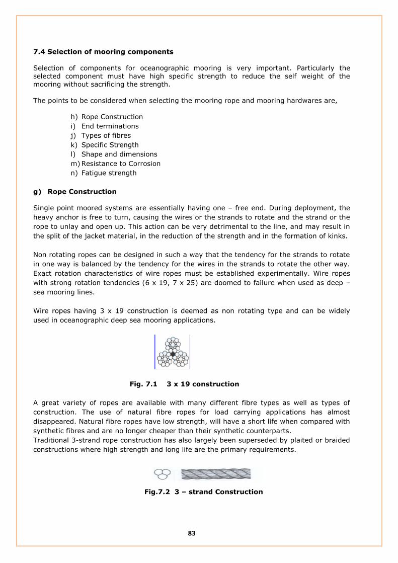
83
7.4 Selection of mooring components
Selection of components for oceanographic mooring is very important. Particularly the
selected component must have high specific strength to reduce the self weight of the
mooring without sacrificing the strength.
The points to be considered when selecting the mooring rope and mooring hardwares are,
h) Rope Construction
i) End terminations
j) Types of fibres
k) Specific Strength
l) Shape and dimensions
m) Resistance to Corrosion
n) Fatigue strength
g) Rope Construction
Single point moored systems are essentially having one – free end. During deployment, the
heavy anchor is free to turn, causing the wires or the strands to rotate and the strand or the
rope to unlay and open up. This action can be very detrimental to the line, and may result in
the split of the jacket material, in the reduction of the strength and in the formation of kinks.
Non rotating ropes can be designed in such a way that the tendency for the strands to rotate
in one way is balanced by the tendency for the wires in the strands to rotate the other way.
Exact rotation characteristics of wire ropes must be established experimentally. Wire ropes
with strong rotation tendencies (6 x 19, 7 x 25) are doomed to failure when used as deep –
sea mooring lines.
Wire ropes having 3 x 19 construction is deemed as non rotating type and can be widely
used in oceanographic deep sea mooring applications.
Fig. 7.1 3 x 19 construction
A great variety of ropes are available with many different fibre types as well as types of
construction. The use of natural fibre ropes for load carrying applications has almost
disappeared. Natural fibre ropes have low strength, will have a short life when compared with
synthetic fibres and are no longer cheaper than their synthetic counterparts.
Traditional 3-strand rope construction has also largely been superseded by plaited or braided
constructions where high strength and long life are the primary requirements.
Fig.7.2 3 – strand Construction

84
This is the oldest and simplest rope construction, consisting of 3 twisted strands laid
together. Three strand ropes are hard wearing and easily spliced.
Multiplait rope consists of 8 strands plaited in pairs, each pair passing over one pair and
under the next. It is easily spliced and the twisted strands offer good resistance to abrasion.
Fig.7.3 Multiplait Construction
h) Rope terminations
Wire rope is terminated with thimbles for connection to the other mooring in the mooring
system.
III. Thimbles
The use of wire rope has lead to the development of thimbles which allow ropes carrying
very high loads to be shackled to other mooring hardwares without damaging the ropes.
The common end terminations and its strength compared with the parent materials are
shown in the figure.
Fig.7.4 Strength of End terminations
IV. Splices
The modern rope constructions (i.e. braided and plaited) allow high strength splices to be
made when the rope has been installed around the thimble. It should be noted that, the
detailed splicing information must be obtained from the rope manufacturer and that these
instructions have to be followed precisely in order to retain the majority of the rope
strength at the splice.

85
Mooring calculations must take into account the reduction of strength resulting from the
splices, usually on the order of 10% for correctly made splices.
i) Types of fibres
Ropes made of synthetic fiber are often used as buoy system anchoring lines. These ropes
do not corrode nor deteriorate appreciably in sea water. Their strength to immersed
weight ratio is excellent. The common materials used in the manufacture of synthetic
fibers,
V. Nylon
This provides high strength, elastic rope with good shock absorbing qualities. However
some ultimate strength is lost due to water abrasion if the rope is permanently immersed
in water.
VI. Polyester
This is widely used to construct high strength, low stretch ropes with good wear
resistance and long life. Their strength is somewhat less than the strength of the nylon
when dry, but it does not change appreciably when wet. Their endurance is very good,
and their resistance to abrasion and chemicals are excellent.
VII. Polypropylene
This has been used for cheap, general purpose rope which floats. However recent
developments in fibre manufacture and rope construction have resulted in moderate
performance ropes, which are considerably less expensive than nylon or polyester ropes.
VIII. Advanced fibres
These include Aramid fibres (trade name Kevlar) and high modulus polyethylene (trade
names Spectra, Dyneema, and Vectran) which have very high strengths associated with
very low stretch. These ropes are also buoyant. However these are very expensive
products being approximately three times the cost of nylon or polypropylene.
j) Shape, Dimensions and Specific Strength
In the design of oceanographic buoy moorings, it is necessary to use ideal shaped and
less dimensioned materials to reduce the forces caused due to drag. Specific weight of
the mooring hardwares is defined as the strength per unit weight of the components.
Hardwares made up of different materials and sizes have higher specific strength then
the one made up of low grade materials. Low grade materials have more weight and
dimension which in turn increases the self weight of the mooring and the mooring force
due to drag.
k) Resistance to corrosion and wear
Rust, electrolytic action and pollution may reduce the normal life of a mooring line. Rust,
which is due to oxidation, occurs both ashore and at sea. Electrolytic action results from a
potential difference between components of a mooring. This is caused by using dissimilar
metals in the same mooring immersed in a common electrolyte, in this case water. It

86
shows as pitting near and in the welds of chain links and in the chain each side of
connecting shackles, over a length, of about 1-2 metres. Electrolytic action can be
significantly reduced by making the buoy body and all the metallic components of the
mooring from the same or very similar grades of steel. Polluted waters also have an
influence on the extent of pitting corrosion. It is mainly observed in the riding part of the
mooring chain.
Wear
The extent to which wear occurs mainly depends on the quality of the materials from
which the mooring is made. Wear is also affected by local environmental conditions, in
particular:
Type of seabed
Amount of sand transport in the water
Depth of water
Weather conditions.
The mooring cannot change these conditions but can only react to them.
A reduction in bar diameter will be observed at the contact point of the links. This may be
due to wear resulting from the movement between links or to local deformation of the
metal caused by impact loads due to the chain ‘snatching’. Snatching can also cause
elongation of the links.
In an area where the seabed is sandy and in particular during bad weather or in strong
tidal currents, a heavy sand transport can be expected. This will cause severe abrasion of
the mooring components. The thrash section of the mooring has the most pronounced
wear as it is continuously moving. Even in waters with small tidal range, where only a
small part of the mooring chain moves over the sea bed, very significant wear may be
found. It is common practice to use a larger size chain for the thrash area to account for
this extra wear.
l) Fatigue Strength
In the marine environment, all the components are subjected to fatigue loading; hence it
is mandatory to have a component having high fatigue strength. For the marine
applications it is broadly accepted by the standards, that the specimen should be tested
for 20,000 cycles at its working load limit.

87
Chapter - 8
Mooring Analysis
8.1 Introduction
Deep sea buoy mooring analysis is used to find the expected load on the mooring line. The
mooring analysis software used is CABLE, developed by Woods Hole Oceanographic
Institution, USA.
8.2 Deep Sea Buoy mooring Analysis:
A sample mooring Analysis was carried out for a depth of 3523 m by using the following
mooring lengths and environmental conditions.
8.2.1 Length of Mooring Ropes:
Depth : 3523 m
Length of wire rope : 550m
Length of Nylon Rope : 320 m
Length of Polypropylene rope : 3173 m
Mooring scope : 1.14
MOORING CONFIGURATION
Depth 3523
Fig. 8.1 Mooring Drawing for MET – Ocean Buoy

88
Environmental Parameters:
The environmental parameters used in the analysis are,
Surface Current Speed = 2 m/s
At 100 m Depth = 1 m/s
At 1000m Depth = 0.5 m/s
At 3500 m/s = 0.1 m/s
Maximum Wave height = 12.5 m
Wave Period = 10.5 s
Results:
The results of the analysis are,
Buoy Draft = 0.737 m
Maximum Tension = 3027.45 N at the depth of 1.96785m (Chain part above the Anchor)
Minimum Tension = 2852.96 N at the depth of 2675.58164 (At the part of Nylon Rope)
Tension below the Buoy = 3016 N (At the chain part below the buoy)
Table 1. Results of the Mooring Analysis
S.NO Tension (N) Breaking Strength
(N) Remarks
1. 3027.45 78, 480 (GI chain) This is the maximum tension experienced in the
mooring line. It can occur at the part of chain
above the anchor.
2. 2852.96 53,955 (Nylon Rope) This is the minimum tension experienced in the
mooring line. It can occur at the part of Nylon
Rope.
3. 3016.59 78, 480 (GI chain) Tension at the chain below the buoy
4. 2950.186 53,955 (PP Rope) Tension at the PP rope line

89
Tension Vs Depth Plot:
Fig. 8.2 Graph of Depth Vs Tension
The maximum tension in the mooring line occurs on the top section of the Anchor and at the
Just below the buoy. In both the locations we are using GI chain, having a breaking strength
of 8000 kg (78480 N), which is far greater than the required strength. In the same fashion,
each and every component in the mooring section was selected.

90
iii. Shallow Water Mooring Analysis
This section describes the mooring analysis carried out for shallow water mooring
deployed at Andaman.
Depth : 10m
Length of wire rope : 10 m
Length of chain : 1 m below the buoy
: 1m above the anchor
Scope : 1.5 - 2
Fig. 8.3 Mooring Drawing for RP 01 Buoy
Environmental parameters:
Current Speed = 2m/s
Wind speed = 6.5 m/s
Wave height = 12.5 m
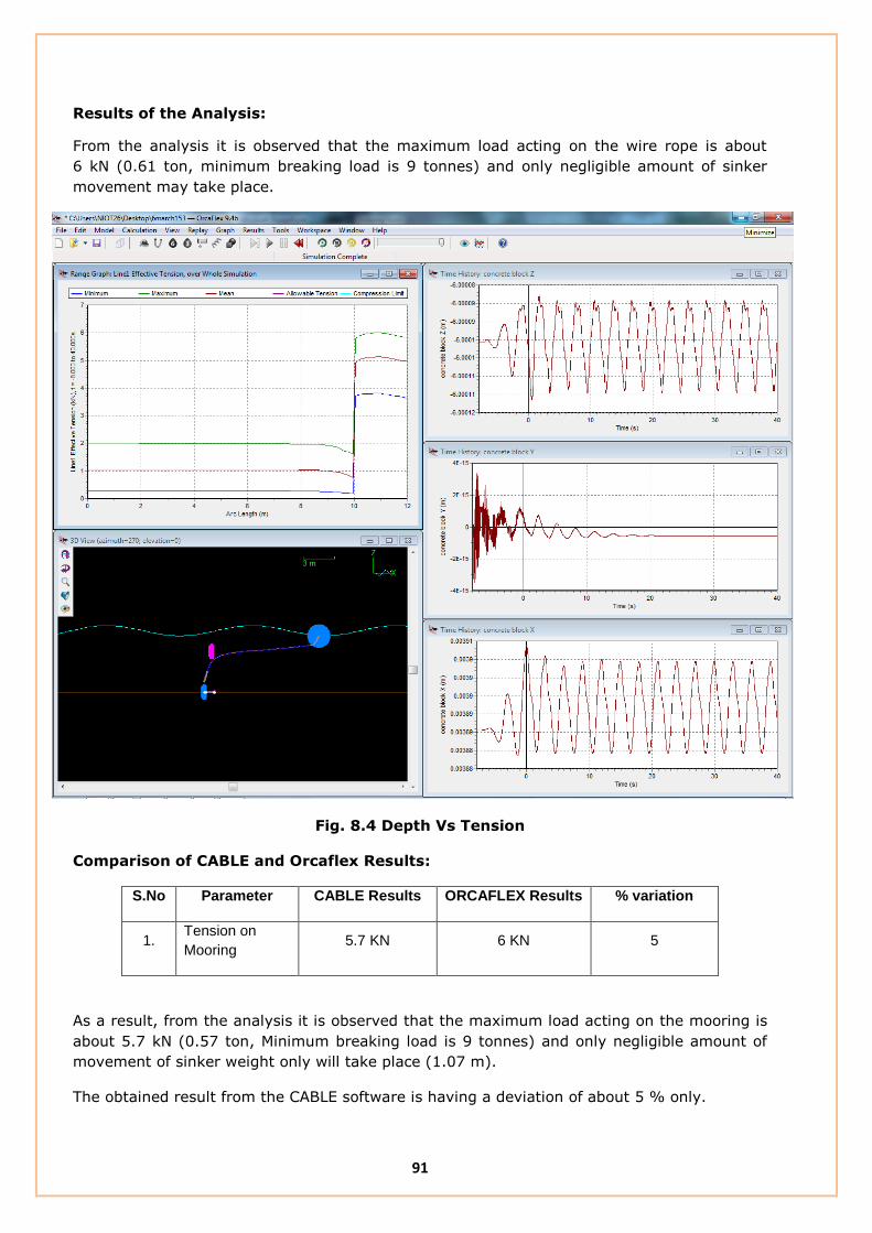
91
Results of the Analysis:
From the analysis it is observed that the maximum load acting on the wire rope is about
6 kN (0.61 ton, minimum breaking load is 9 tonnes) and only negligible amount of sinker
movement may take place.
Fig. 8.4 Depth Vs Tension
Comparison of CABLE and Orcaflex Results:
S.No Parameter CABLE Results ORCAFLEX Results % variation
1. Tension on
Mooring 5.7 KN 6 KN 5
As a result, from the analysis it is observed that the maximum load acting on the mooring is
about 5.7 kN (0.57 ton, Minimum breaking load is 9 tonnes) and only negligible amount of
movement of sinker weight only will take place (1.07 m).
The obtained result from the CABLE software is having a deviation of about 5 % only.

92
Annexure: 1 Specification:
This section describes the specifications of the mooring ropes and hardwares presently in use
at NIOT.
COMBINATION WIRE ROPE:
Strand Construction : 6 x 19 + Independent Wire Rope Core (IWRC)
Sheathing : Each strand of the rope except IWRC shall be
Sheathed with polypropylene.
Type of lay : Right hand Ordinary Lay
Nominal diameter : 18 mm
Minimum Breaking Load : 9 tons
Tensile grade of wire : 1770 N/ mm2.
Galvanization : Wires shall be type “A” galvanized,
as per IS 1835/Equivalent
Lubrication : Medium duty marine application
Length of the rope : 550 m per spool
NYLON ROPE:
Nominal diameter of the rope : 16 mm
Minimum breaking load : 5.5 tons
Specific gravity : Around 1.14
Melting Point : 260° C.
Length of the rope : 320m per spool
Water absorption : max 4%
Breaking Elongation : 21%

93
Load Vs Elongation curve for Nylon Rope:
Ref: M/s D.Koronakis, Greece
POLYPROPYLENE ROPE
Nominal diameter of the rope : 18 mm
Minimum breaking load : 5.5 tons
Specific gravity : 0.99
Melting Point : 260° C
Water absorption : 1%
Breaking Elongation : 12-14%
LOAD-ELONGATION CURVE
USED KAPANYLON
0
10
20
30
40
50
60
70
80
90
100
0 5 10 15 20 25 30
ELOGATION (%)
TE
NS
ILE
ST
RE
NG
TH
(%
)

94
Load Vs Elongation curve for Polypropylene Rope:
Ref: M/s D.Koronakis, Greece
LOAD-ELONGATION CURVE
USED KAPA-FLEX
0
10
20
30
40
50
60
70
80
90
100
0 2 4 6 8 10 12 14
ELOGATION (%)
TE
NS
ILE
ST
RE
NG
TH
(%
)

95
MOORING HARDWARES:
Sl.no Item description Material Size
Maximum
Breaking Load
(Tonnes)
1 G.I.Bow shackle Carbon steel 1”/25.4mm 8.5
2 G.I. chain (short
link)
Carbon steel 1”/25.4mm 8.5
3 Swivel Carbon steel 1”/25.4mm 8.5
4 Pear ring or
Connecting ring
Carbon steel 1”/25.4mm 8.5
5 Open type G.I.
thimble
Steel To suit 18 mm
rope ----
Need
The performance of presently used mooring systems showed mixed experience. There are
cases wherein mooring deployed by NIOT remained in position for few years. However recent
years, technological developments have taken place in materials, construction and
specification of mooring components used and mooring analysis is also improved. Hence
there is a need to re-look into the present design and recommend newer design and new
material could be adopted form the experience of similar mooring systems being used
globally.
In spite of the success of the present moorings, the followings points need to be addressed:
It is recommended by the Nylon rope manufacturer to reconsider the use of Rotating
type of Combination Wire rope with the Non – rotating type of Nylon and
Polypropylene rope.
Optimization of mooring rope lengths for different buoy systems to suite for different
operating conditions.
Improvising the specifications of Mooring ropes and hardwares in par with different
materials used by other organizations and recent advancements in the offshore
mooring Technology.
Complete mooring system should be supplied and certified by a single supplier.

96
Suggested points
S.No Specification of existing Components Suggested Modification Remarks
1 WIRE ROPE JACKETED WIRE ROPE
Construction : 6 x 19 + IWRC Construction : 3 x 19
Sheathing : Each strand of the rope except IWRC. Sheathing : Polypropylene Jacketed.
Type of lay : Right hand Ordinary Lay, Rotational type Type of lay : Torque Balanced
Diameter : 18 mm Diameter : 11 mm
Minimum Breaking Load : 9 tons Minimum Breaking Load :9 tons
Tensile grade of wire : 1770 N/ mm2 Tensile grade of wire :1770 N/ mm2
Length of the rope : 550 m per spool Length of the rope : 550 m per spool
Make : M/s Bharat Wire Ropes, India Make : M/s Mooring Systems INC, USA
: M/S Seaproof Solutions, Norway
: M/s Loos and Co, USA
2 NYLON ROPE NYLON ROPE
Construction : 12 strand, Plaited
Construction : 12 strand, braided : 8 strand, plaited
Nominal diameter of the rope: 16 mm Nominal diameter of the rope :16 mm, 18 mm
Minimum breaking load : 5.5 tons Minimum breaking load : 7.8 tons
Length of the rope :320m for Met - Ocean Buoy Length of the rope :320m for Met - Ocean Buoy
: 160 m for Tsunami Buoy : 160 m for Tsunami Buoy
Breaking Elongation : 21 % Breaking Elongation : 21 %
Make : M/s D. Koronakis. S.A, Greece Make : M/s D. Koronakis. S.A, Greece
: M/s Columbian Speciality products
Division of Plymkraft, INC
: M/s Yale Cordage
: M/s Erling Haug, Norway
3 POLYPROPYLENE ROPE POLYPROPYLENE ROPE
Construction :12 strand, Construction :12 strand,
Nominal diameter of the rope :18 mm : 3 Strand Nominal diameter of the rope :18 mm
Minimum breaking load :5.5 tons Minimum breaking load :5.5 tons
Length of the rope :2000 m, 1000 m Length of the rope :2000 m, 1000 m
Breaking Elongation : 12 % Breaking Elongation : 12 %
Make : M/s D. Koronakis. S.A, Greece Make : M/s D. Koronakis. S.A, Greece
: M/s Erling Haug, Norway
4 Shackles
Type : Bow Shackle, Bolt and Nut Type. Type : Bow Shackle, Bolt and Nut Type.
Dimension : 1", 3/4" Dimension: 3/4", 5/8"
Material : carbon steel Material : Alloy steel
Working Load Limit : 8.5 tonnes and 4.75 tonnes Breaking Load : 4.75 tonnes and 3.25 tonnes
Should be Fatigue tested
Make : M/s Sealinkers PVT Ltd, India Make : M/s Grossby Group, USA
: M/s Gunnebo, Norway

97
S.No Specification of existing Components Suggested Modification Remarks
5 Chain
Type : Short Link GI chain Type : Long Link GI chain
Dimension: 1" Dimension: 3/4",
Material : carbon steel Material : Alloy steel
Working Load Limit : 8.5 tonnes Breaking Load : 4.75 tones
Should be Fatigue tested
Make: M/s Grossby Group, USA
: M/s Gunnebo, Norway
6 Bearing Swivel
Type : Eye & Eye Type : Eye & Eye
Working Load Limit : 5.5 tonnes Working Load Limit : 5.5 tonnes
Should be Fatigue tested
Make : M/s Sealinkers PVT Ltd, India Make : M/s Grossby group, USA
: M/s M/s Gunnebo, Norway
7 Thimble
Type : open type GI Thimble Type: Polyeurethane Thimble
8 Connecting Ring
Type : Oblong Master Link Type : Oblong Master Link
Diameter : 19 mm Working Load Limit : 5.4 tonnes
Working Load Limit : 5.4 tonnes Should be Fatigue tested
Make : M/s Sealinkers PVT Ltd, India Make : M/s Grossby group, USA
: M/s M/s Gunnebo, Norway
9 Sinker weight
Weight : 2 tonnes Weight : 2 tonnes
Shape : Cube Shape : Cylindrical
Make: M/s Express engineering, India Make: M/s Express engineering, India
10 Anchor:
Weight : 130 kg Weight : 130 kg
Type : Denforth Anchor Type : Denforth Anchor
Make: M/s Eurotech Systems, India Make: M/s Eurotech Systems, India

98
Annexure: 2 List of Buoy Deployment locations:
Bay of Bengal Arabian Sea
Met Ocean Buoy
Buoy
Location
Latitude
(N)
Longitude
(E)
Depth(m) Buoy
Location
Latitude
(N)
Longitude
(E)
Depth(m)
BD01 18°49’ 00” 89°00’ 00” 2110 AD01 19° 00’ 00” 67° 00’ 00” 3210
BD02 18°30’ 00” 88°00’ 00” 2176 AD02 15° 00’ 00” 69° 00’ 00” 3867
BD03 15° 30’ 00” 90° 00’ 00” 2648 AD03 12° 00’ 00” 69°00’ 00” 4173
BD04 14°12’ 00” 82°54’ 00” 3369 AD04 08° 00’ 00” 73° 00’ 00” 2250
BD05 10° 30’ 00” 94° 00’ 00” 3149 AD05 06°30’ 00” 68°50’ 00” 2002
BD06 10° 00’ 00” 88° 30’ 00” 3432 SW02 17°21’ 06” 70°42’ 08” 2220
BD07 06°15’ 00” 85°53’ 00” 3870 RP02 10°52’ 55” 72°12’ 68” 20
NIOT Tsunami Buoy & SAIC Buoy
TB05 11° 00’ 00” 89° 30’ 00” 3210 TB12 21° 24’ 00” 64° 06’ 00” 2552
TB06 15° 00’ 00” 90° 00’ 00” 2736 STB02 20° 48’ 00” 65° 20’ 25”
TB08 12° 30’ 00” 85° 30’ 00” 3285 TB10 06°54’ 00” 86°59’ 00” 3860

99
Annexure : 3 Suite of sensors
The table below describes the list of Met – Ocean buoy sensors and its make.
SL.NO SENSOR MAKE OF THE SENSOR
1 Wind LAMBRECHT
R M YOUNG
2 Humidity/Air Temperature ROTRONICS
3 Air Pressure VAISALA
4 Wave Measurement SEATEX MRU
5 Conductivity AND Temperature VALEPORT,ALLEC, SEABIRD
6 Satellite Transceiver T&T /INMARSAT
7 Precipitation R M YOUNG
8 Radiation Sensor EPPLY LAB
9 Compass KVH

100
References
11. R.Balaji, S.A.sannasiraj and V.sundar, “ Physical model studies on discus buoy in
regular, random, and double peak spectral waves”, Indian Journal of Marine sciences,
Vol. 36(1), March 2007, pp. 18 – 26
12. R. P. Trask and R. A. Weller, “Moorings” Woods Hole Oceanographic Institution
technical report.
13. NIOT Buoy Manual and standard operating procedures.
14. Buoy Engineering by Henri O. Berteaux, Willey Sons 1978
15. IALA design Guidelines for Offshore Moorings.
16. http://www.envirtech.com/index.html
17. http://www.saic.com/about
18. http://www.fio.org.cn/english/index.asp
19. http://www.oceanor.no
20. http://www.pmel.noaa.gov