design of maleic anhydride (man) production plant group 4 afiq noor bin tuah 11857 mohd fadhli bin...
TRANSCRIPT
DESIGN OF MALEIC ANHYDRIDE (MAN)
PRODUCTION PLANT
GROUP 4AFIQ NOOR BIN TUAH 11857MOHD FADHLI BIN SAYUTTI 12012CHE MUHAMMAD BUKHARI BIN CHE MOHD RAZALI 11908CHE FATIN HUMAIRA BINTI CHE YUSUF 11907NUR HANIE BINTI ZAMRI 12140
1
PLANT DESIGN I (CBB 4013)INTERIM ORAL PRESENTATION
SEMESTER MAY 2012

OUTLINE PRESENTATION
Introduction
Literature Review
Preliminary Hazard Analysis
Conceptual Design Analysis
Process Flow Diagram
Heat Integration
Conclusion

INTRODUCTION

4
BACKGROUND OF DESIGN PROJECT
Two main feedstock
Benzene n-Butane
Product
Maleic Anhydride

5
BACKGROUND OF DESIGN PROJECT
Source: http://www.icis.com/Articles/2003/10/10/525310/chemical-profile-maleic-anhydride.html
Application of MAN
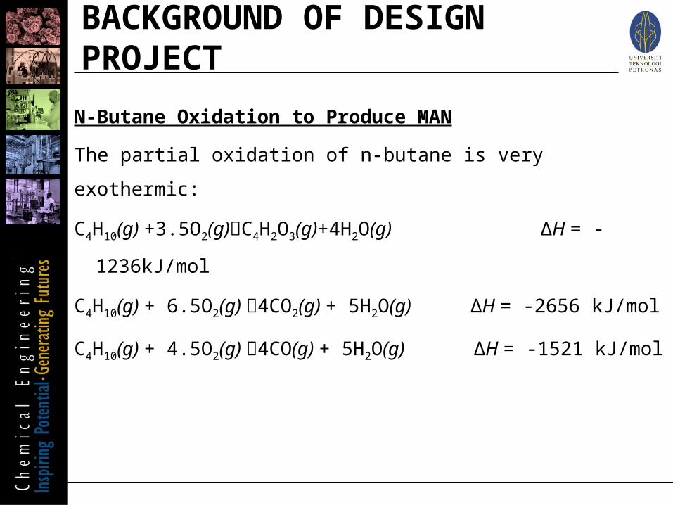
N-Butane Oxidation to Produce MAN
The partial oxidation of n-butane is very exothermic:
C4H10(g) +3.5O2(g)C4H2O3(g)+4H2O(g) ∆H = -1236kJ/mol
C4H10(g) + 6.5O2(g) 4CO2(g) + 5H2O(g) ∆H = -2656 kJ/mol
C4H10(g) + 4.5O2(g) 4CO(g) + 5H2O(g) ∆H = -1521 kJ/mol
BACKGROUND OF DESIGN PROJECT

Drawbacks of Benzene as Feedstock: • Health hazards from unreacted benzene vapor• Rising cost of benzene• Rising demand in other industries
Alternate Feed Stock (Butane): • Low cost• Easy availability• Less hazardous to health
PROBLEM STATEMENT

OBJECTIVES
To design a Maleic Anhydride production plant using mixed butane as raw material

Feed Preparation
Oxidation Reaction
Crude Maleic Anhydride Recovery
Crude Maleic Anhydride Purification
Energy Recovery
SCOPE OF STUDY

LITERATURE REVIEW

FEED INFORMATION
PROPERTIES• Physical Properties• Chemical Properties
MARKET STUDY• Price

PHASE BEHAVIOR
Density (liquid) 600 kg/m³
Molar Mass 58.12 g/mol
Melting Point -140 to -134 °C
Boling Point -1 to 1 °C
LIQUID PROPERTIES
Heat capacity, cp 132.42 J/(mol K)GAS PROPERTIES
Heat capacity, cp 98.49 J/(mol K) at 25°C
FEED PHYSICAL PROPERTIES
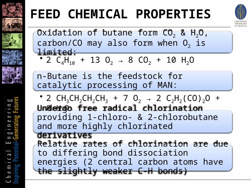
Oxidation of butane form CO2 & H2O, carbon/CO may also form when O2 is limited: • 2 C4H10 + 13 O2 → 8 CO2 + 10 H2O
n-Butane is the feedstock for catalytic processing of MAN:• 2 CH3CH2CH2CH3 + 7 O2 → 2 C2H2(CO)2O + 8 H2O
Undergo free radical chlorination providing 1-chloro- & 2-chlorobutane and more highly chlorinated derivatives
Relative rates of chlorination are due to differing bond dissociation energies (2 central carbon atoms have the slightly weaker C-H bonds)
FEED CHEMICAL PROPERTIES

Source: http://price.alibaba.com/search/priceSearch.htm?q=butane
FEED PRICE

PRODUCT INFORMATION
PROPERTIES• Physical Properties• Chemical Properties
MARKET STUDY• Price• Demand
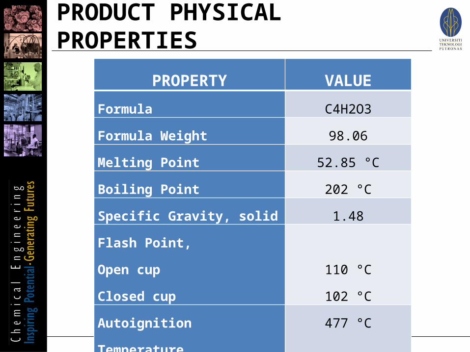
PROPERTY VALUEFormula C4H2O3
Formula Weight 98.06
Melting Point 52.85 °C
Boiling Point 202 °C
Specific Gravity, solid 1.48
Flash Point,Open cupClosed cup
110 °C102 °C
Autoignition Temperature 477 °C
Heat Capacity, solid 0.1199 kJ/K mol
PRODUCT PHYSICAL PROPERTIES

Acid Chloride Formation
Alkylation
AmidationHydration & Dehydration
Isomerization3 Active Sites & 1 Double Bond with 2 Carbonyl O2
PRODUCT CHEMIICAL PROPERTIES

Capacity : 30,000 TPA
PRODUCT DEMAND
Demand in Asia:184,370 TPA
Production Rate in Malaysia (TCL Malaysia): i. 1997 – 35,000 TPAii. 2008 – 60,000 TPA
Source: http://www.thirumalaichemicals.com/maleic.html & http://www.tclresearch.com/library/presentation.pdf

Maleic Anhydride Price: 1476.92 USD/tone
Conversion:
1476.92 x 0.001 x 3.1824 = 4.7
Source: http://price.alibaba.com/price/priceLeafCategory.htm?categoryId=100001625&spuId=100070280
PRODUCT PRICE
SITE LOCATION
Criteria
Selection Process
Decision

1. Location with respect to the marketing area2. Raw material supply3. Transport facilities4. Availability of labor5. Availability of utilities: water, fuel, power6. Availability of suitable land7. Environmental impact & effluent disposal8. Local community considerations9. Climate10. Political and strategic considerations
SITE LOCATION: Criteria

Raw Materials
Butane Imported GPP, PGB
Utilities Power Sultan Iskandar Power Station
Paka Power Plant
Water Johor Waterworks Department, Loji Air Sungai Layang, Syarikat Air Johor
Terengganu Waterworks Department, Bukit Sah, Sg Cherol, Seberang Tayor, Kemasik
Steam (Unknown) Centralised Utilities Facilities (CUF), Kerteh
Natural Gas
(Unknown) Gas Processing Plant (1,2,3,4), KertehGas Processing Plant (5,6), Paka
SITE LOCATION: Selection ProcessFactors Site Location

Available Area 44.16 ha 352.70 ha Land Price RM 86.00 – 237.00 /
meter2RM 45.00 – 105.00 / meter2
Transportation Seaport Johor Port Kemaman Port
Roadway PLUS Highway (Bukit Kayu Hitam-Singapore)Highway Pasir Gudang-Tanjung Kupang-Tuas Singapore
Factors Site Location
SITE LOCATION: Selection Process

Training Centre Institut Latihan Perindustrian Pasir Gudang
Terengganu Advanced Technical Institute, Pusat Latihan Petroliam PETRONAS
SITE LOCATION: Selection ProcessFactors Site Location

Natural gas easily obtained from PETRONAS Gas Berhad (PGB) at Kerteh & Paka
Utilities directly supplied by Centralised Utilities and Facilities (CUF) at Kerteh
Existence of major transportation networks offers wider range of marketability options, locally and internationally
Strategically located: Kemaman Port allows ease of transportation all over the world with all year round deep water sea port
Economical local manpower due to the existence of several training centre institutions
TELUK KALONG INDUSTRIAL AREA
SITE LOCATION: Decision
POSSIBLE PROCESS ROUTE
Option 1
Option 2

Mixture of butane & air fed
to reactor
Butane reacts with O2 to form
MAN
Reactor effluent sent to absorber & contacted with
H2O
Light gases are removed and
MAN converted to maleic acid
Liquid effluent sent to 2nd
reactor (maleic acid broken
down to MAN & H2O)
Reactor effluent sent to
distillation column to
separate MAN & H2O
POSSIBLE PROCESS ROUTE: Option 1

Gas mixture of O2 & n-butane fed to reactor
Partial oxidation to MAN by
contacting feed gas with VPO
catalyst
The cooled gas flows to absorber
and contacted with DBP as
solvent
Absorption liquor flows to stripper
column
Liquid side draw of crude MAN is removed from rectifying zone
The crude product flows to
distillation column & form
low boiling materials
POSSIBLE PROCESS ROUTE: Option 2

PRELIMINARY HAZARDANALYSIS

Colleferro Maleic Anhydrate Plant, Italy
i. The temperature in the kettle increased rapidly and
unexpectedly - exploded.
ii. Due to an incomplete discharge of water at the end of the
washing phase.
iii. The introduction of maleic anhydride, contacting water at
temperature higher than 100˚C caused the release of heat,
which increased the evaporation rate.
PREVIOUS ACCIDENTS

Incident
Fire Explosion of kettle and column
Localizes collapse Pressurization of kettle and column
Rupture of the kettle tube bundle and inlet
of steam
Obstruction of the head condenser (no
condensation of head vapors)
Reaction of the feed in the kettle with an undesired substance
Abnormal water in the kettle
(exothermic reaction)
Inlet of steam in the kettle due to poor
seal on heating bundle
Inlet of steam from the jacketed pipe
between kettle and bottom
Inlet of demineralized water in the column
due to seal defects of the condenser tube
bundle
Residue of wash water in the kettle due to
pipe or discharge valve blockage
Inlet of wash water in the kettle due to imperfect closing of
the inlet valve
Combustion of the product in the kettle or
in the column
LOGIC TREE FOR MAN INCIDENT

Chemicals Flammability Toxicity Reactivity
Exposure Standard
Auto-ignition Temp oC
Flash Point
oC
LEL (%)
UEL (%)
Oral (LD50)
Inhalation (LC50)
Dermal(LD50)
TWA
Propane` 468.0 -104.0 2.4 9.5 N/A N/A N/A Reacts strongly with oxidizing agents.
1000 ppm
i - Butane 432.0 -82.0 1.4 8.3 N/A 57 parts per
hundred (pph)
Rat
N/A Stable but acts as oxidizing agent at elevated temperature of 435 0C
800 ppm
n- Butane 430.0 -60.0 1.8 8.4 N/A 658 g/m3/4hr
Rat
N/A Stable but acts as oxidizing agent at elevated temperature of 435 0C
800 ppm
IDENTIFICATION OF HAZARD
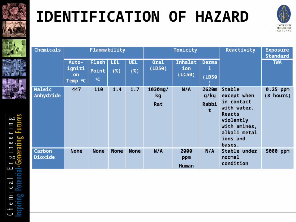
Maleic Anhydride
447 110 1.4 1.7 1030mg/kg
Rat
N/A
2620mg/kg
Rabbit
Stable except when in contact with water. Reacts violently with amines, alkali metal ions and bases.
0.25 ppm (8 hours)
Carbon Dioxide
None None None None N/A 2000 ppm
Human
N/A Stable under normal condition
5000 ppm
Chemicals Flammability Toxicity Reactivity
Exposure Standard
Auto-ignition Temp oC
Flash
Point oC
LEL
(%)
UEL
(%)
Oral (LD50) Inhalation (LC50)
Dermal
(LD50)
TWA
IDENTIFICATION OF HAZARD
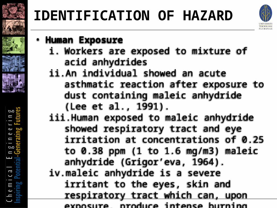
• Human Exposure i. Workers are exposed to mixture of acid anhydridesii. An individual showed an acute asthmatic reaction
after exposure to dust containing maleic anhydride (Lee et al., 1991).
iii. Human exposed to maleic anhydride showed respiratory tract and eye irritation at concentrations of 0.25 to 0.38 ppm (1 to 1.6 mg/m3) maleic anhydride (Grigor’eva, 1964).
iv. maleic anhydride is a severe irritant to the eyes, skin and respiratory tract which can, upon exposure, produce intense burning sensations in the eyes and throat with coughing and vomiting.
IDENTIFICATION OF HAZARD

Personal Protection for Exposure Control
• To control or even avoid the exposure of those chemicals
• Wearing eye/face protection to avoid eye contact with the chemicals.
• Proper skin protective equipment such as coveralls or lab coats must be worn to prevent from skin exposure
The safety design of the facilities
• Spill detection methods • Emergency notification
procedures• Community contacts for
notification and advice on evacuation needs
• Fire prevention and protection
• Provisions for spill containment/clean-up
• Environmental protection• Compliance with
applicable local regulations or laws
Risk reduction
• Hazard Elimination
• Consequence Reduction
• Likelihood reduction
PREVENTION

Several related local acts and regulations for compliance before operating new plant:
1. Occupational Safety and Health Act (OSHA) 1994- to reduce work related injuries, illness and death
and incidentally to cut resulting costs 2. Environment Quality Act (EQA) 1974
- prevention, abatement and control of pollution and enhancement of environment by restricting discharge of waste which applied to the whole Malaysia
3. Factories and Machinery Act (FMA) 1967- to provide for the control of factories with
respect to matters relating to the safety, health and welfare of person
REGULATIONS & GUIDELINES

CONCEPTUAL DESIGN ANALYSIS

SELECTED PROCESS: OPTION 2

PRELIMINARY REACTOR OPTIMIZATION
REACTION PATH
SELECTION OF CATALYST
OPERATING PARAMETER

C4H10 (g) + 3.5 O2 (g) C4H2O3(g) + 4 H2O (g) ∆H = -1236 kJ/mol (1)
C4H10 (g) + 6.5 O2 (g) 4 CO2 (g) + 5 H2O (g) ∆H = -2656 kJ/mol (2)
C4H10 (g) + 4.5 O2 (g) 4 CO (g) + 5 H2O (g) ∆H = -1521 kJ/mol (3)
REACTION PATH
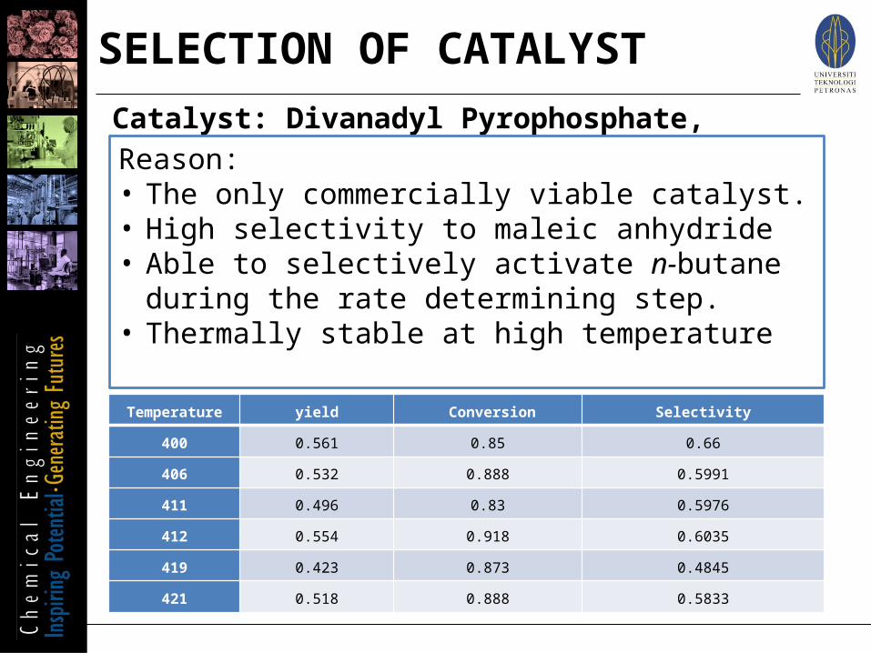
Catalyst: Divanadyl Pyrophosphate, (VO)2P2O 7 Reason:• The only commercially viable catalyst.• High selectivity to maleic anhydride • Able to selectively activate n -butane during the rate
determining step.• Thermally stable at high temperature
Temperature yield Conversion Selectivity
400 0.561 0.85 0.66
406 0.532 0.888 0.5991
411 0.496 0.83 0.5976
412 0.554 0.918 0.6035
419 0.423 0.873 0.4845
421 0.518 0.888 0.5833
SELECTION OF CATALYST

•400°C
•Based on literature study on optimum operating range
•Safety consideration
Temperature
•170kPa
•Oxidation reaction is not pressure dependent
•Cheaper cost
Pressure
•Molten Salt
•High heat capacity
•Stable at high temperature and not flammable
Heating Medium
•1.7 mol% of N-butane
•LFL and UFL (1.86%-4.61%)
Inlet Feed concentration
•Conversion
: 85%
•Selectivity
: 0.66
•Yield
: 0.561
Conversion, selectivity and yield of Maleic Anhydride
OPERATING PARAMETER

PROCESS SCREENING
LEVEL 1: MODE OF OPERATION
LEVEL 2: INPUT-OUTPUT STRUCTURE
LEVEL 3: REACTOR SYSTEM
LEVEL 4: SEPARATION SYSTEM
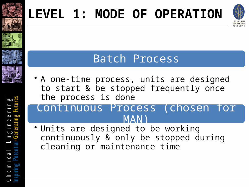
Batch Process
• A one-time process, units are designed to start & be stopped frequently once the process is done
Continuous Process (chosen for MAN)• Units are designed to be working continuously & only be
stopped during cleaning or maintenance time
LEVEL 1: MODE OF OPERATION

Why Continuous Process is Chosen?
Production Rate
• Our capacity: 31,375 metric ton/year (bigger than 10 million pound per year/4 535.9237 metric ton per year)
Market Study
• MAN is not seasonable product (widely use in industry in all year long)
• Demand for MAN will continue to grow
Operational Problem
• The plant only involve vapour & liquid phase with no slurry
• The equipment is not periodically started & stopped for cleaning purpose
LEVEL 1: MODE OF OPERATION

A simplified representation of process flow sheet which focuses on raw material feed, products and by-products
Decisions suggested by Douglas:
1. Should we purify the feed stream before they enter the process?2. Should we remove or recycle a reversible by-product? 3. Should we use a gas recycle and purge stream?4. Should we not bother to recover and recycle some reactants?
LEVEL 2: INPUT-OUTPUT STRUCTURE
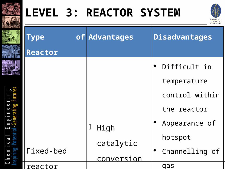
Type of Reactor Advantages Disadvantages
Fixed-bed reactor High catalytic
conversion Easy to operate
Difficult in temperature control within the reactor
Appearance of hotspot
Channelling of gas Difficulty in unit
cleaning or service Difficulty in catalyst
replacement
LEVEL 3: REACTOR SYSTEM

Type of Reactor Advantages Disadvantages
Fluidized-bed
reactor
Uniform particle
mixing
Uniform temperature
distribution
Avoid hot spot
Good temperature
control
Higher capacity for
MAN production
Easier in catalyst
replacement
Higher pumping
power requirement
Back mixing problem
Lack of understanding
Scale up problem
Erosion of internal
components
Entrainment of
particles
High catalyst volume
demand
LEVEL 3: REACTOR SYSTEM

Fixed Bed Reactor
Cheaper initial capital cost
Sufficient time for maintenance
LEVEL 3: REACTOR SYSTEM
Desired production of MAN is within capacity
Fluidized bed Reactor is too complex
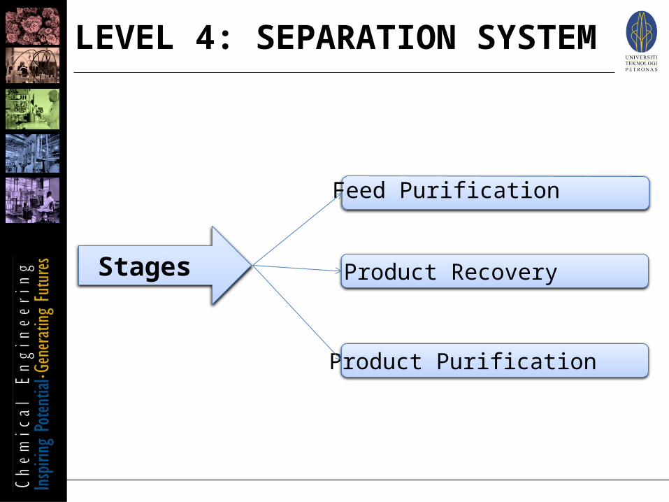
Stages
Feed Purification
Product Recovery
Product Purification
LEVEL 4: SEPARATION SYSTEM
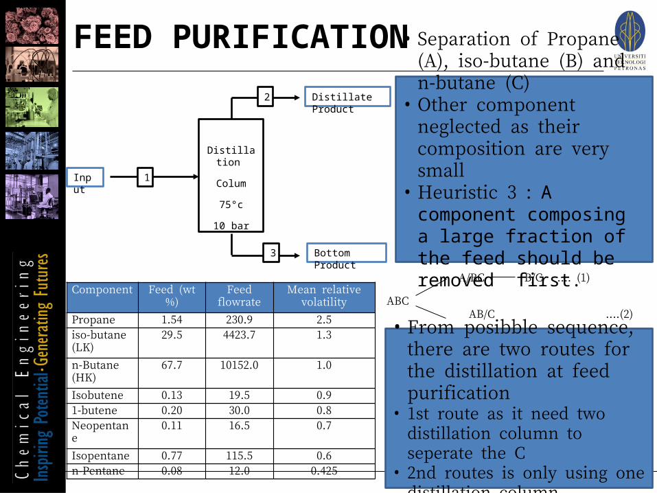
Distillation
Colum
75°c
10 bar
1
2
3
Input
Distillate Product
Bottom Product
ABC AB/C ....(2)
A/BC B/C.... (1)Component Feed (wt%) Feed
flowrateMean relative
volatility
Propane 1.54 230.9 2.5iso-butane (LK)
29.5 4423.7 1.3
n-Butane (HK)
67.7 10152.0 1.0
Isobutene 0.13 19.5 0.91-butene 0.20 30.0 0.8Neopentane 0.11 16.5 0.7Isopentane 0.77 115.5 0.6n-Pentane 0.08 12.0 0.425
• Separation of Propane (A), iso-butane (B) and n-butane (C)
• Other component neglected as their composition are very small
• Heuristic 3 : A component composing a large fraction of the feed should be removed first.
• From posibble sequence, there are two routes for the distillation at feed purification
• 1st route as it need two distillation column to seperate the C
• 2nd routes is only using one distillation column
FEED PURIFICATION
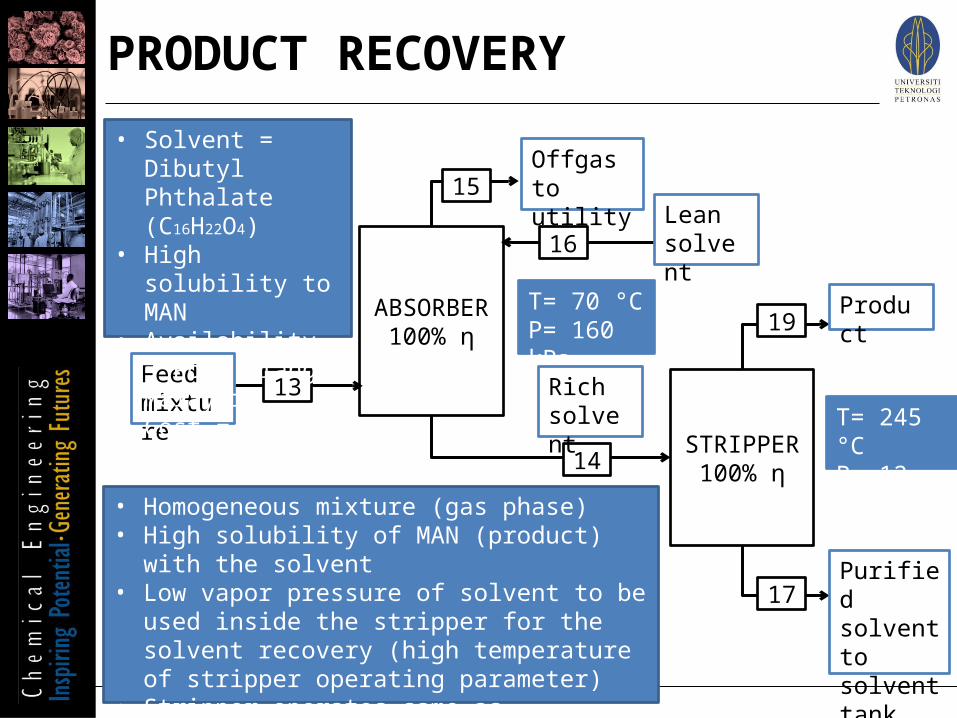
ABSORBER100% η
STRIPPER100% η
13
14
16
15
17
19
• Homogeneous mixture (gas phase)• High solubility of MAN (product) with the solvent• Low vapor pressure of solvent to be used inside the
stripper for the solvent recovery (high temperature of stripper operating parameter)
• Stripper operates same as distillation column (no stripping gas injected)
T= 70 °CP= 160 kPa
T= 245 °CP= 12 kPa
Feed mixture
Offgas to utility
Lean solvent
Rich solvent
Product
Purified solvent to solvent tank
• Solvent = Dibutyl Phthalate (C16H22O4)
• High solubility to MAN
• Availability = Port Klang, Malaysia
• Cost =
PRODUCT RECOVERY

• Separation of Maleic Anhydride (A) and water (B). • Heuristic 3 : A component composing a large fraction of the feed
should be removed first.AB A/B
• From posibble sequence, only one route for the distillation at product purification.
• Maleic Anhydride and water shall be directly seperated.
Product purification
110°c
10bar
19
20
21
Input
Distillate Product
Bottom Product
Component Feed (wt%)
Feed flowrate
Mean relative volatility
Maleic Anhydride (HK)
99.1 3961.5 3
Water (LK) 0.9 180.2 5
PRODUCT PURIFICATION

Mass Balance around Reactor
Mass Balance around Feed Distillation Column
Mass Balance around Flash Vessel
Mass Balance around Absorber
Mass Balance around Stripper
Mass Balance around Product Distillation Column
PRELIMINARY MASS BALANCE

INPUT OUTPUT
MASS BALANCE AROUND REACTOR

MASS BALANCE AROUND FEED DISTILLATION COLUMN

MASS BALANCE AROUND FLASH VESSEL
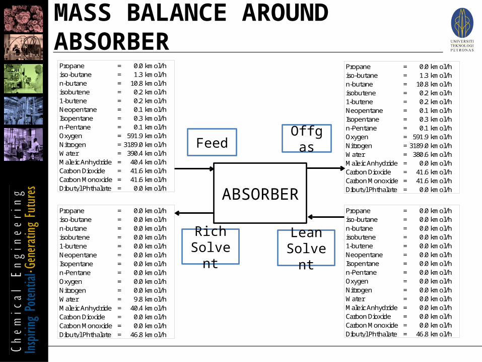
Propane = 0.0 kmol/hiso-butane = 1.3 kmol/hn-butane = 10.8 kmol/hisobutene = 0.2 kmol/h1-butene = 0.2 kmol/hNeopentane = 0.1 kmol/hIsopentane = 0.3 kmol/hn-Pentane = 0.1 kmol/hOxygen = 591.9 kmol/hNitrogen = 3189.0 kmol/hWater = 390.4 kmol/hMaleic Anhydride = 40.4 kmol/hCarbon Dioxide = 41.6 kmol/hCarbon Monoxide = 41.6 kmol/hDibutyl Phthalate = 0.0 kmol/h
Propane = 0.0 kmol/hiso-butane = 1.3 kmol/hn-butane = 10.8 kmol/hisobutene = 0.2 kmol/h1-butene = 0.2 kmol/hNeopentane = 0.1 kmol/hIsopentane = 0.3 kmol/hn-Pentane = 0.1 kmol/hOxygen = 591.9 kmol/hNitrogen = 3189.0 kmol/hWater = 380.6 kmol/hMaleic Anhydride = 0.0 kmol/hCarbon Dioxide = 41.6 kmol/hCarbon Monoxide = 41.6 kmol/hDibutyl Phthalate = 0.0 kmol/h
Propane = 0.0 kmol/hiso-butane = 0.0 kmol/hn-butane = 0.0 kmol/hisobutene = 0.0 kmol/h1-butene = 0.0 kmol/hNeopentane = 0.0 kmol/hIsopentane = 0.0 kmol/hn-Pentane = 0.0 kmol/hOxygen = 0.0 kmol/hNitrogen = 0.0 kmol/hWater = 9.8 kmol/hMaleic Anhydride = 40.4 kmol/hCarbon Dioxide = 0.0 kmol/hCarbon Monoxide = 0.0 kmol/hDibutyl Phthalate = 46.8 kmol/h
Propane = 0.0 kmol/hiso-butane = 0.0 kmol/hn-butane = 0.0 kmol/hisobutene = 0.0 kmol/h1-butene = 0.0 kmol/hNeopentane = 0.0 kmol/hIsopentane = 0.0 kmol/hn-Pentane = 0.0 kmol/hOxygen = 0.0 kmol/hNitrogen = 0.0 kmol/hWater = 0.0 kmol/hMaleic Anhydride = 0.0 kmol/hCarbon Dioxide = 0.0 kmol/hCarbon Monoxide = 0.0 kmol/hDibutyl Phthalate = 46.8 kmol/h
ABSORBER
Feed Offgas
Rich Solvent
Lean Solvent
MASS BALANCE AROUND ABSORBER

STRIPPER
Feed Product
Propane = 0.0 kmol/hiso-butane = 0.0 kmol/hn-butane = 0.0 kmol/hisobutene = 0.0 kmol/h1-butene = 0.0 kmol/hNeopentane = 0.0 kmol/hIsopentane = 0.0 kmol/hn-Pentane = 0.0 kmol/hOxygen = 0.0 kmol/hNitrogen = 0.0 kmol/hWater = 9.8 kmol/hMaleic Anhydride = 40.4 kmol/hCarbon Dioxide = 0.0 kmol/hCarbon Monoxide = 0.0 kmol/hDibutyl Phthalate = 46.8 kmol/h
Propane = 0.0 kmol/hiso-butane = 0.0 kmol/hn-butane = 0.0 kmol/hisobutene = 0.0 kmol/h1-butene = 0.0 kmol/hNeopentane = 0.0 kmol/hIsopentane = 0.0 kmol/hn-Pentane = 0.0 kmol/hOxygen = 0.0 kmol/hNitrogen = 0.0 kmol/hWater = 9.8 kmol/hMaleic Anhydride = 40.4 kmol/hCarbon Dioxide = 0.0 kmol/hCarbon Monoxide = 0.0 kmol/hDibutyl Phthalate = 0.0 kmol/h
Propane = 0.0 kmol/hiso-butane = 0.0 kmol/hn-butane = 0.0 kmol/hisobutene = 0.0 kmol/h1-butene = 0.0 kmol/hNeopentane = 0.0 kmol/hIsopentane = 0.0 kmol/hn-Pentane = 0.0 kmol/hOxygen = 0.0 kmol/hNitrogen = 0.0 kmol/hWater = 0.0 kmol/hMaleic Anhydride = 0.0 kmol/hCarbon Dioxide = 0.0 kmol/hCarbon Monoxide = 0.0 kmol/hDibutyl Phthalate = 46.8 kmol/h
Solvent Recovery
MASS BALANCE AROUND STRIPPER

MASS BALANCE AROUND PRODUCT DISTILLATION COLUMN
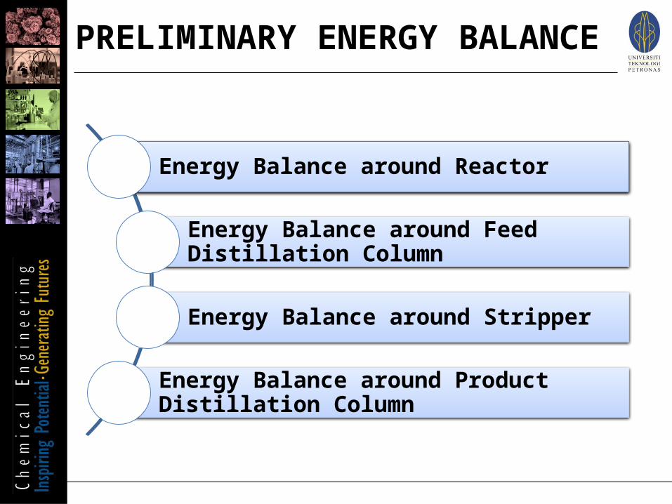
Energy Balance around Reactor
Energy Balance around Feed Distillation Column
Energy Balance around Stripper
Energy Balance around Product Distillation Column
PRELIMINARY ENERGY BALANCE

Entalphy for propane (input) = ΔHf°(i) + cp(i) (T i – Tref) = -103.8 + 0.074 (300 -25)= -83.6 kJ/mol
Entalphy for propane (ouput) = ΔHf°(i) + cp(i) (T i – Tref) = -103.8 + 0.074 (400 -25)= -76.2 kJ/mol
ENERGY BALANCE AROUND REACTOR

Q = ΔH= (ΣnoutH out – ΣninH in) / 3600= (-76452537.53 - 27266534.1)/3600= -28810.8 kW or -28.8 MW
ENERGY BALANCE AROUND REACTOR

Condenser
Reboiler
ENERGY BALANCE AROUND FEED DISTILLATION COLUMN

Condenser
Reboiler
Gas (191.8°C --> 25°C) Gas (25°C) --> Liquid (25°C) Liquid (25°C --> 190.8°C) Components mCpdT (kJ/hr) mλ (kJ/hr) mCpdT (kJ/hr) Water -5484553.4 42873.4 54516.6 Maleic Anhydride -1103534.1 76674.3 96918.2 Q (KJ/h) -1158379.5 79547.7 51434.8 Qtotal (kw) -659.4
Gas (354.1°C --> 25°C) Gas (25°C) --> Liquid (25°C) Liquid (25°C --> 355.1°C) Components mCpdT (kJ/hr) mλ (kJ/hr) mCpdT (kJ/hr) Dibutyl Phthalate -4154.1 1463.3 4166.6 Q (KJ/h) -4154.1 1463.3 4166.6 Qtotal (kw) 2200
ENERGY BALANCE AROUND STRIPPER

Condenser
Reboiler
ENERGY BALANCE AROUND PRODUCT DISTILLATION COLUMN
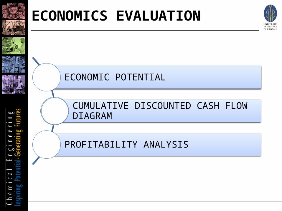
ECONOMIC POTENTIAL
CUMULATIVE DISCOUNTED CASH FLOW DIAGRAM
PROFITABILITY ANALYSIS
ECONOMICS EVALUATION

EP 1 = Product Value – Cost of Raw Material = 147,462,876 RM/year -66,286,494 RM/year = 81,176,382 RM/year
EP 2 = EP 1 + By Product Value = 81,176,382 RM/year + 0 = 81,176,382 RM/year
EP 3 = EP 2 – Utility Cost = 81,176,382 RM/year- 19,954,598 RM/year =61,221,784 RM/year
ECONOMIC POTENTIAL
0 1 2 3 4 5 6 7 8 9 10 11 12 13 14 15 16 17 18 19 20
-500,000,000
0
500,000,000
1,000,000,000
1,500,000,000
2,000,000,000
2,500,000,000
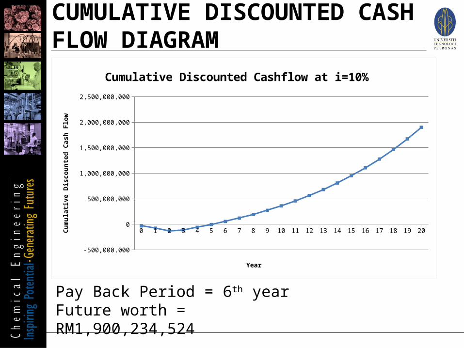
Cumulative Discounted Cashflow at i=10%
Year
Cum
ulati
ve D
iscou
nted
Cas
h Fl
ow
Pay Back Period = 6th yearFuture worth = RM1,900,234,524
CUMULATIVE DISCOUNTED CASH FLOW DIAGRAM

ITEMS PRICE (RM/YEAR)
RAW MATERIAL 66,286,494
PRODUCT 147,462,876
CAPEX 132,114,000.00
OPEX 92,603,095.90
FUTURE WORTH
PAYBACK PERIOD
70
PROFITABILITY ANALYSIS

PROCESS FLOW DIAGRAM(BEFORE
HEAT INTEGRATION)

HEAT INTEGRATION
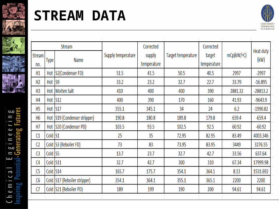
STREAM DATA
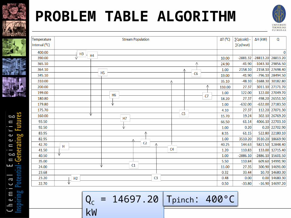
QC = 14697.20 kW Tpinch: 400°C
PROBLEM TABLE ALGORITHM

QC = 14697.20 kW
COMPOSITE CURVE

Process Recovery: 29748.1 kW
GRAND COMPOSITE CURVE

HEAT EXCHANGER NETWORK

Cold utility Hot utility
Before integration (kW) 29743.82 44182.14
After integration (kW) 14697.20 0
Energy saved (kW) 15046.62 44182.14
Percent of energy saved (%) 50.6 100
TOTAL ENERGY SAVING

PROCESS FLOWDIAGRAM
(AFTERHEAT INTEGRATION)

80
PROCESS FLOW DIAGRAM

81
MATERIAL BALANCE TABLE

CONCLUSION

Our design of MAN production plant using n-butane as raw material is feasible with the process route selected & realistic with the demand & market of MAN with the following specifications:i. Plant Site Location: Teluk Kalong Industrial Area, Kemaman,
Terengganuii. Capacity: 30,000 TPAiii. Production Rate: 31,375 TPAiv. Purity: 98%v. Future Worth: RM1,900,234,524vi. Pay Back Period: 6th yearvii. Energy Recovery: 100% Hot Utility, 50% Cold Utility
CONCLUSION