design of long term solutions for solid waste management · transfer station design – definition...
TRANSCRIPT
This Project is funded by the European Union
SWIM and Horizon 2020 Support Mechanism Working for a Sustainable Mediterranean, Caring for our Future
Presented by:
Mr. Faouzi BEN AMOR, Environmental of Expert - MeHSIP
SWIM and Horizon 2020 SM Title of Meeting
28-29 March 2018, Beirut, Lebanon
Design of Long Term Solutions for Solid Waste Management
Transfer Stations

Transfer Station design – Definition
Waste Transfer Station is a facility where waste from multiple sources is consolidated into high volume vehicles for transport to a regional waste disposal site.
Transfer Station design – Design elements
Factors Impacting Size • Total tons/day of material to flow through
• Size & capacity of collection vehicles using the facility
• Length of time materials at the facility (storage space)
• Loading & unloading times
• Peak conditions; i.e. maximum # of vehicles in facility at once (design for this)
• Type of processing to occur
• Transfer trailer capacity & waiting time for loading
• Hours of station operation
Transfer Station design – Types
Generally there are 3 types of transfer stations
• Direct-Discharge (Direct Dump)
• Platform/Pit
• Or a combination of both
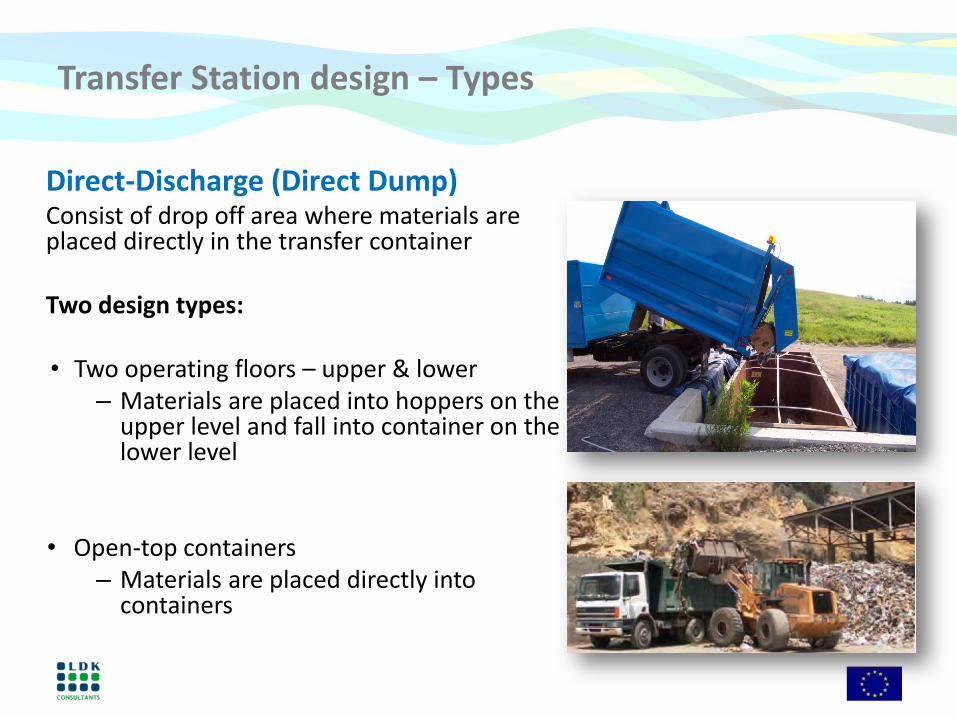
Transfer Station design – Types
Direct-Discharge (Direct Dump) Consist of drop off area where materials are placed directly in the transfer container
Two design types: • Two operating floors – upper & lower
– Materials are placed into hoppers on the upper level and fall into container on the lower level
• Open-top containers – Materials are placed directly into
containers

Transfer Station design – Definition
Platform / Pit Consist of an upper & lower level
• Upper level is a tipping floor where
materials are dumped
• Lower level contains open-top trailers & materials are pushed into them from the upper level
• Open top trailer / container can be either compacting or non-compacting
Transfer Station design – Types of TS
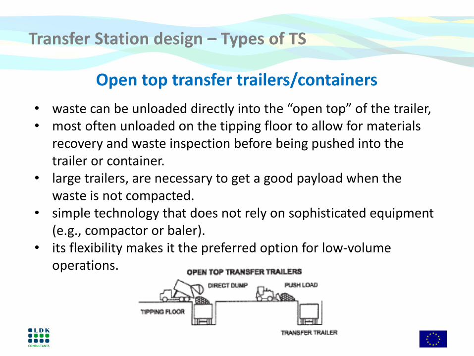
Open top transfer trailers/containers
• waste can be unloaded directly into the “open top” of the trailer, • most often unloaded on the tipping floor to allow for materials
recovery and waste inspection before being pushed into the trailer or container.
• large trailers, are necessary to get a good payload when the waste is not compacted.
• simple technology that does not rely on sophisticated equipment (e.g., compactor or baler).
• its flexibility makes it the preferred option for low-volume operations.

Transfer Station design – Types of TS
Surge pit • not a loading technology but an intermediate step normally used
with open-top or pre-compactor systems. • pit can store peak waste flow thus reducing the number of
transfer trailers/containers needed. • A tracked loader or bulldozer is used to compact the waste
before loading, increasing payload. • Because waste is often unloaded directly into the surge pit, this
technology might deter materials recovery and waste screening efforts

Transfer Station design – Types of TS
Stationary compactors • Stationary compactors use a hydraulic ram to compact waste
into the transfer trailer/container.
• Because the trailer/container must be designed to resist the compactive force, it is usually made of reinforced steel.
• The heavy trailer/container and the weight of the onboard unloading ram reduce the payload available for waste.
• This technology is declining in popularity.

Transfer Station design – Types of TS
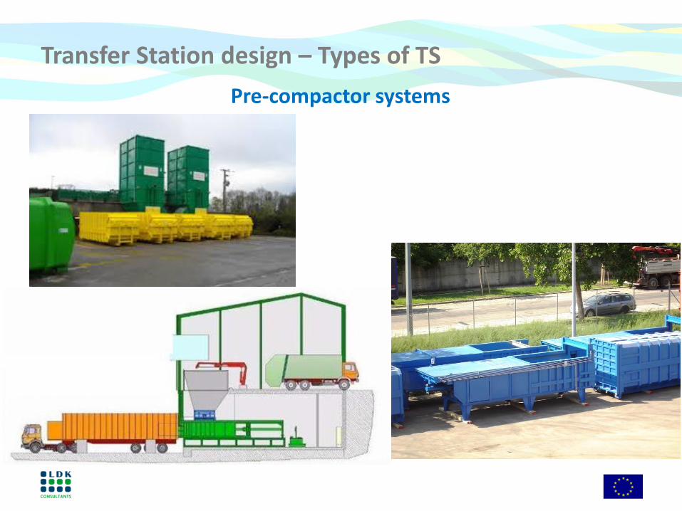
Pre-compactor systems
• Pre-compactor systems use a hydraulic ram inside a cylinder to create a dense “log” of waste.
• The log is pushed into a trailer/container that uses “walking floor” technology to unload or relies on a tipper at the landfill to unload by gravity.
• Most pre-compactor installations have two units in case one unit requires repair.
• The capital cost is relatively high at more than $250,000 per unit, but the superior payload can offset these initial costs.
Transfer Station design – Types of TS
Pre-compactor systems

Transfer Station design – Types of TS
Bailing stations
• Balers are units that compress waste into dense, self-contained bales. Wire straps may be used to hold the bales intact.
• Bales usually moved by forklifts and transported by flatbed trailers.
• Baler units can also be used for recyclables (paper and metal).
• Payloads are very high, but so are capital costs.
• Most baling stations have at least 2 units in case one is down, and they cost more than $500,000 apiece.
• Normally used only in high-volume operations, and special equipment or accommodations might be required at the landfill.
Transfer Station design – Design aspects
• Potential sites identification, screening, public consultation, selection, topographic survey, geotechnical investigation;
• Study of the road trips of incoming vehicles and their last collection point to the transfer center;
• Study of the road trips of vehicles leaving the transfer center towards the controlled landfill;
• Preferential routes must be defined according to the capacities of roads and nuisances to the population;
• Preferential journeys must be imposed on the drivers of outgoing vehicles.
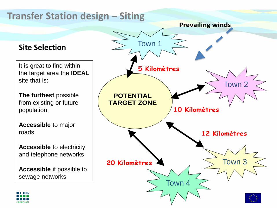
Transfer Station design – Siting
Town 4
Site Selection Town 1
Town 2
Town 3
POTENTIAL TARGET ZONE
10 Kilomètres
12 Kilomètres
20 Kilomètres
5 Kilomètres
Prevailing winds
It is great to find within
the target area the IDEAL
site that is:
The furthest possible
from existing or future
population
Accessible to major
roads
Accessible to electricity
and telephone networks
Accessible if possible to
sewage networks

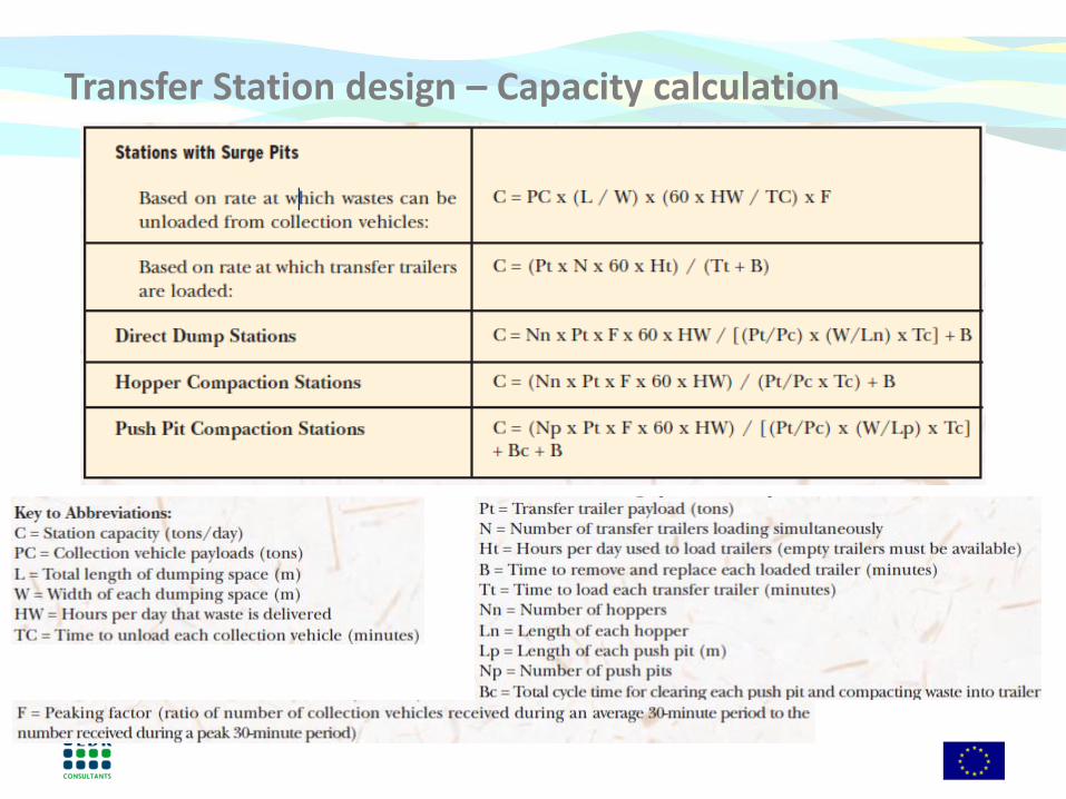
Transfer Station design – Capacity calculation
• A useful exercise is calculating how much tipping floor space a facility would require to store a full day’s waste in case of extreme emergency.
• One approach to estimating the required tipping floor space is to begin with a base area of 150 m2 and add to it 1 m2 for each ton of waste received in a day (assuming the waste will be temporarily piled 2 m high on the tipping floor).
• For example, if the facility receives 100 tpd, a tipping floor space of 250 m2 would be required (150 m2 + (100 tpd x 1 m2/ton) = 250 m2).
Transfer Station design – Capacity calculation

Transfer Station design – Typical setup 12 t/j
10 t/d
13 t/d
Landfill
Transfert station
Town TS Landfill
Enfidha 7 59
Hergla 17 54
Sidi Bou Ali 15 37
Distances Km
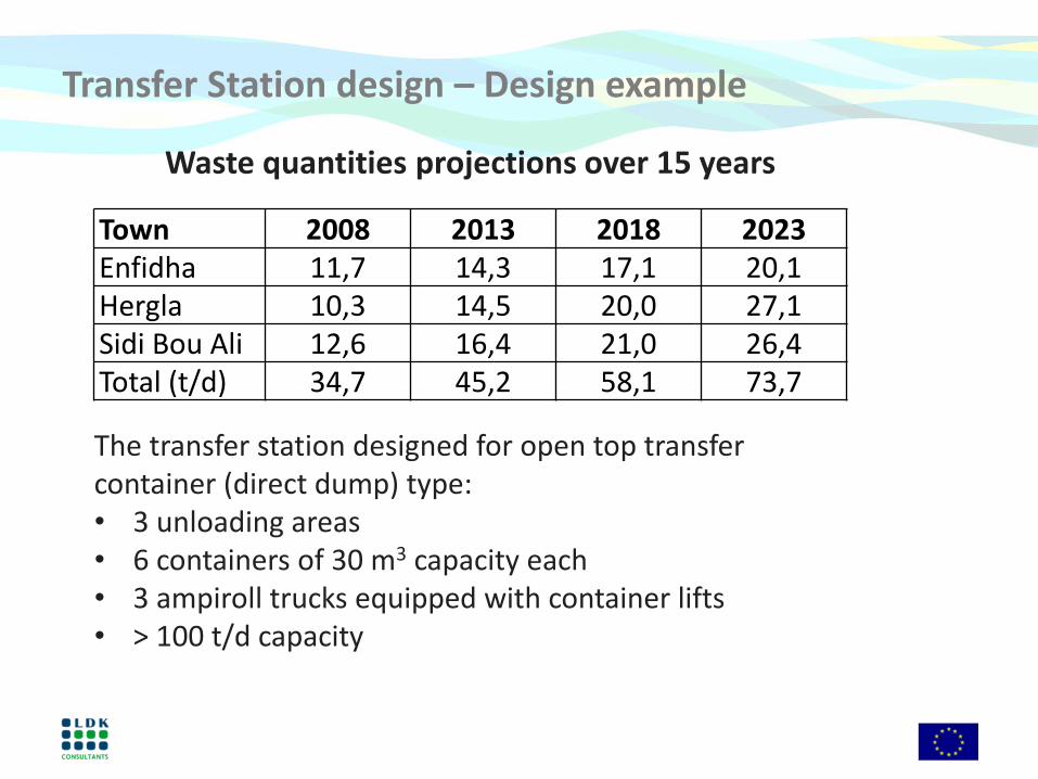
Transfer Station design – Design example
Town 2008 2013 2018 2023
Enfidha 11,7 14,3 17,1 20,1
Hergla 10,3 14,5 20,0 27,1
Sidi Bou Ali 12,6 16,4 21,0 26,4
Total (t/d) 34,7 45,2 58,1 73,7
The transfer station designed for open top transfer container (direct dump) type: • 3 unloading areas • 6 containers of 30 m3 capacity each • 3 ampiroll trucks equipped with container lifts • > 100 t/d capacity
Waste quantities projections over 15 years
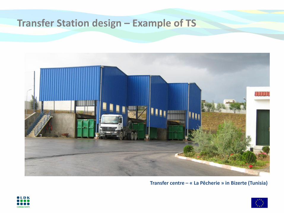
Transfer Station design – Example of TS
Transfer centre – « La Pêcherie » in Bizerte (Tunisia)

Transfer Station design – Example of TS
Transfer centre – « La Pêcherie » in Bizerte (Tunisia)
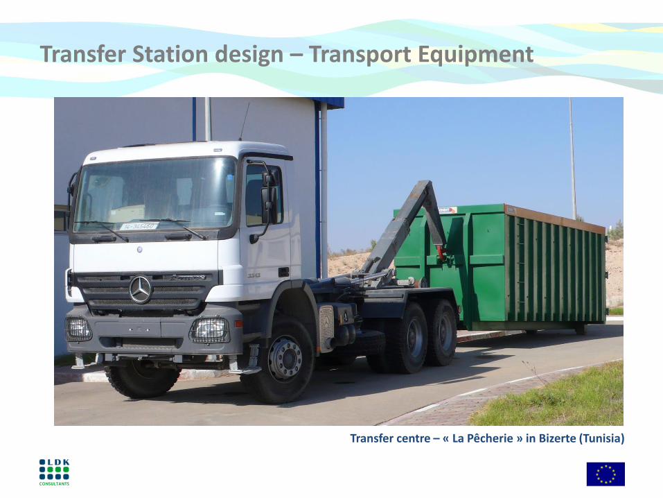
Transfer Station design – Transport Equipment
Transfer centre – « La Pêcherie » in Bizerte (Tunisia)

Transfer Station design – Infrastructure components
Fences and gate
Electrical transformer
Administrative, guard, weight control buildings
Weigh scales
Unloading area
Loading area
Internal roads
Litter control
Odor control
Leachate management
Rainwater management
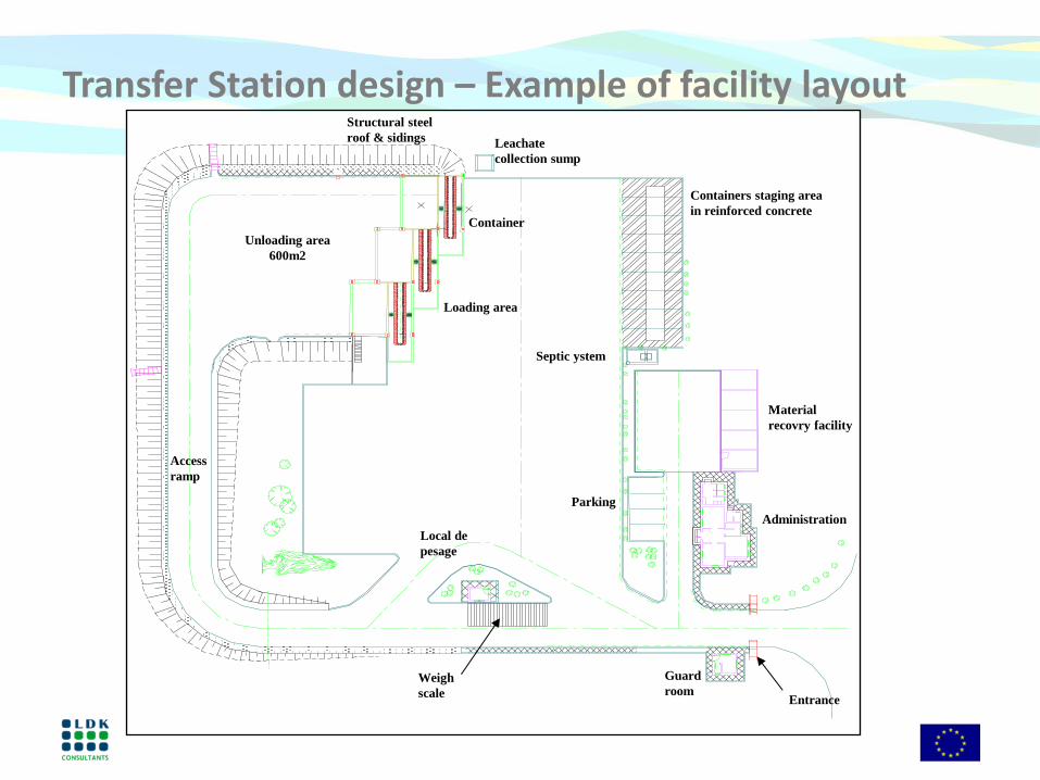
Transfer Station design – Example of facility layout
Weigh
scale
Guard
room Entrance
Administration
Unloading area
600m2
Containers staging area
in reinforced concrete
Parking
Septic ystem
Loading area
Container
Leachate
collection sump
Local de
pesage
Access
ramp
Structural steel
roof & sidings
Material
recovry facility

For further information
Website
www.swim-h2020.eu E: [email protected]
LinkedIn Page
SWIM-H2020 SM LinkedIn
Facebook Page
SWIM-H2020 SM Facebook
SWIM-H2020 SM

This Project is funded by the European Union
SWIM and Horizon 2020 Support Mechanism Working for a Sustainable Mediterranean, Caring for our Future
Thank you for your attention.