design of human exo-skeleton suit for rehabilitation of
TRANSCRIPT
Procedia Engineering 51 ( 2013 ) 544 – 553
1877-7058 © 2013 The Authors. Published by Elsevier Ltd.Selection and peer-review under responsibility of Institute of Technology, Nirma University, Ahmedabad.doi: 10.1016/j.proeng.2013.01.077
Chemical ,Civil and Mechanical Engineering Tracks of 3rd Nirma University International Conference.(NUiCONE 2012)
Design of Human Exo-Skeleton Suit for Rehabilitation of HemiplegicPeople
Shah Mihir Rajesh*SRM University,Department of Mechatronics Engineering,gg Kattankulatur,Chennai-603203,INDIA.
Abstract
The end of the 20th century witnessed the development of Exo-Skeleton Suits. These suits were fabricated for various reasons and their main focus was to reduce human effort.They were made so that the daily activities of human beings are simplified and therefore to be lessstressful. So the advancement of Exo-Skeleton Suits started and were made for areas ranging from defence to medicine. But much focuswas given to increase human strength.Even the recent Human Exo-Skeleton Suit HAL(Hybrid Assistive Limb) which is a multi-purpose suit but its primary aim is to reduce human force for work.In this paper the focus is shifted to the paralyzed people especially Hemiplegicpeople.Hemiplegia is a disorder in which one half of the Human body Fails to perform its functions, including one Arm and one Leg i.e.half of the body is Paralysed. As a result of this, they are not able to walk and do other physical activities.The main reason of Hemiplegia found is due to stroke and in many cases it is hereditary .Recovery from stroke is difficult and the treatment is prolonged hence the Exo-Skeleton Suit H1 is designed and proposed in this paper. Enabling these people to walk using a wearable Exo-Skeleton Suit-H1, which iscost-effective and will enable walking is the real motive behind the ideology.H1 Suit is designed to focus purely for hemiplegic peopleunlike HAL which has multi-applications and is extremely costly for a common man. Instead of conventional motors, which are used inearlier Exo-Skeleton Suit for the movement of limbs, Pneumatic actuation is used for better locomotion. The Control of this actuation is done by means of a fixed Potentiometer. The device is tested using Softwares like Festo Fluid Sim and Pro-Engineer which is exhibited in this paper. A Test Case is performed and satisfying Results were obtained. In its Later stages of implementation the similar device will bemade for Paraplegia- the medical condition in which both the Legs are Paralysed.
© 2012 Published by Elsevier Ltd. Selection and/or peer-review under responsibility of the Institute of Technology NirmaUniversity, Ahmedabad.
Keywords: Hemiplegia ; Exo-Skeleton Suit ; Human-Machine ; Walking ; Pneumatic Actuation.
Nomenclature
Greek Symbols
Angle traced by calf muscle (Lower pa
Ang
Abbreviations
L1 Length of Thigh (m)
* Corresponding author. Tel.:+91-9043713952.E-mail address: [email protected]
Available online at www.sciencedirect.com
© 2013 The Authors. Published by Elsevier Ltd.Selection and peer-review under responsibility of Institute of Technology, Nirma University, Ahmedabad.
545 Shah Mihir Rajesh / Procedia Engineering 51 ( 2013 ) 544 – 553
L2 Length of Leg (m) CG Centre of Gravity GC Gait Cycle HAL Hybrid Assistive Limb
1.Introduction
The word 'plegia' means weakness and 'Hemi' implies one side of the body. Hence, 'hemiplegia' means complete paralysis of one half of the body, including one arm and leg. Any disease or injury in the motor centers of the brain can cause hemiplegia. Hemiplegia is a more severe form of 'hemiparesis' wherein one half of the body is only weakened. It is also very different from the conditions of paraplegia & quadriplegia, which are commonly confused with hemiplegia. Paraplegia is paralysis in both legs, below the waist. Quadriplegia is paralysis below the neck and is also usually the result of a spinal cord injury. Many conditions give rise to hemiplegia. Generally, an injury to the right side of the brain will cause a left-sided hemiplegia while an injury to the left side of the brain will cause a right-sided hemiplegia [8]. There are Medical Methods to cure this, but it is prolonged and the treatment is costly. Exo-Skeleton Suit is a Electro-Mechanical device which is wearable and has a Pre-defined control loop, which performs the execution according to the requirement. Exo-Skeletons have been p [2], [3].Since then many improvements are made and Exo-Skeletons are used in many applications like Military, Medical, Rescue Operations etc. The latest Exo-Skeleton Suit is HAL-5(Hybrid Assitive Limb),which is developed in the University of Tsukuba by Prof.Saikai and his students[4-6] .HAL is the most advanced Exo-Skeleton which is capable of lifting heavy loads and also enable aged and physically weak people to walk ,climb stairs, hold objects etc. It has two control systems -one is Bio-Cybernic and other is Robotic Autonomous Control System. The Cost of HAL-5 Type B suit is around Fourty thousand Dollars, which is very expensive. The suit is expensive because it has a lot of advanced sensing technologies and high battery life. Thus H1 is proposed to enable common working class people who are suffering from Hemiplegia to walk with ease. The H1 suit is purely focused for Hemiplegic people.
2. Related work
As mentioned earlier, an injury in right brain will cause left hemiplegia whereas an injury in the left brain will cause right hemiplegia, so keeping this fact in mind, the H1 Suit is designed. The H1 consists of Pneumatic Actuators, Potentiometers, Compressed Air Supply, Micro-Controllers, Flow Control Valve, DC Motor with Encoder (Quadrature and Absolute type) as key Components. It is Pneumatically Powered instead of a high torque motor. The reason is that it will have a better life and less battery voltage will be consumed compared to a high torque motor and thus making it eco-friendly. Though Pneumatic actuation will be a bit slower compared to that of a motor, but it will have a considerable high life. Even in HAL- 5 , the Battery life is five hours only [9]. In H1 a Potentiometer is fixed on the upper arm ( Triceps Brachii Muscle) in the other section of the body which is not affected by hemilegia. There are two Pneumatic Actuators which are connected to the body by means of Body Frame of the suit- One is fixed at the back Thigh muscle and One is fixed at the Calf muscle. There is a Flow Control Valve which is intermediate between the Actuators and the Main Air Supply Tank and this is responsible for the Speed of Extension/Retraction of the Piston Cylinder and thereby the Walking Speed of the Person. If this is not used then there will be sudden extension/retraction which might damage the muscles and skin tissues and even affect the dynamics of the Structure. The DC motor is mounted on the knob of FCV (Flow Control Valve).An Encoder is attached to the rear end of the DC Motor Shaft which will count the turns it has revolved Clockwise/Anti-Clockwise and send the signal to the Micro-Controller. The Compressed Air Supply will be in the form of Couple of Bottles which are Air-tight with Check-Valve in it and can be easily carried by the person on the back. The entire structure is made using Aluminium, thus making it light weight which will be easy to carry and walk. This is one of the advantages of this Exo-Skeleton Suit over HAL 5 which weighs around twenty-three kilograms [9]. In the later Stage there will be another Pneumatic actuator which will be placed in such a way that as the piston cylinder on the leg is retracted it actuates and thereby the hemiplegic hand will move forward thereby maintaining the dynamic balance of the body with limb movements. There are two more actuators which are fixed to the Hemiplegic leg and will always be in an extended position to reduce the weight on the affected Leg along with a spring an rubber sole mechanism.
3. Control architecture
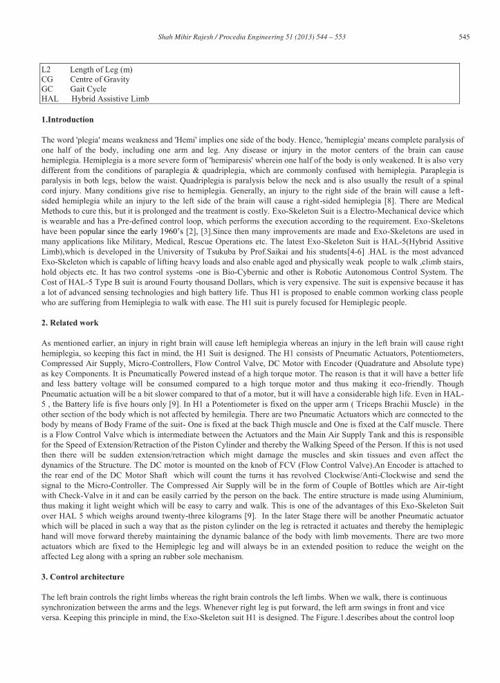
The left brain controls the right limbs whereas the right brain controls the left limbs. When we walk, there is continuous synchronization between the arms and the legs. Whenever right leg is put forward, the left arm swings in front and vice versa. Keeping this principle in mind, the Exo-Skeleton suit H1 is designed. The Figure.1.describes about the control loop
546 Shah Mihir Rajesh / Procedia Engineering 51 ( 2013 ) 544 – 553
which is followed in the suit. In the figure, is the body of person who is suffering from right hemiplegia, because he has an injury in the left part of the brain. So, to deal with this problem a potentiometer is fixed rigidly on the left upper arm. When left hand swings in front, the value of the resistance will increase and it reaches a threshold point. This threshold point is that resistance at which the arm swing angle is maximum. Thus, as the swing angle increases the resistance value increases and vice versa. The Potentiometer sends these readings to the Micro-Controller. Immediately the Micro-Controller sends signals to the Solenoid Operated DCV (Directional Control Valve).While it is increasing its angle, there is a DC Motor which is fixed to the Flow Control Valve is revolving and thereby the stroke length of the piston cylinder is increasing. There are two pneumatic actuators one at the back thigh muscle and one at the calf muscle. The back thigh muscle actuator
ns. The role of Encoder is to calculate the amount of rotations performed by the DC Motor and send it to the Micro-Controller so as to control the motor in opposite directions by the same amount of rotations and both the actuators are retracted once the feet touches the ground by means of a force sensor, which is attached to the rubber sole of the affected feet.
Figure.1. The Control Architecture of H1 suit for Right Hemiplegic Subject.
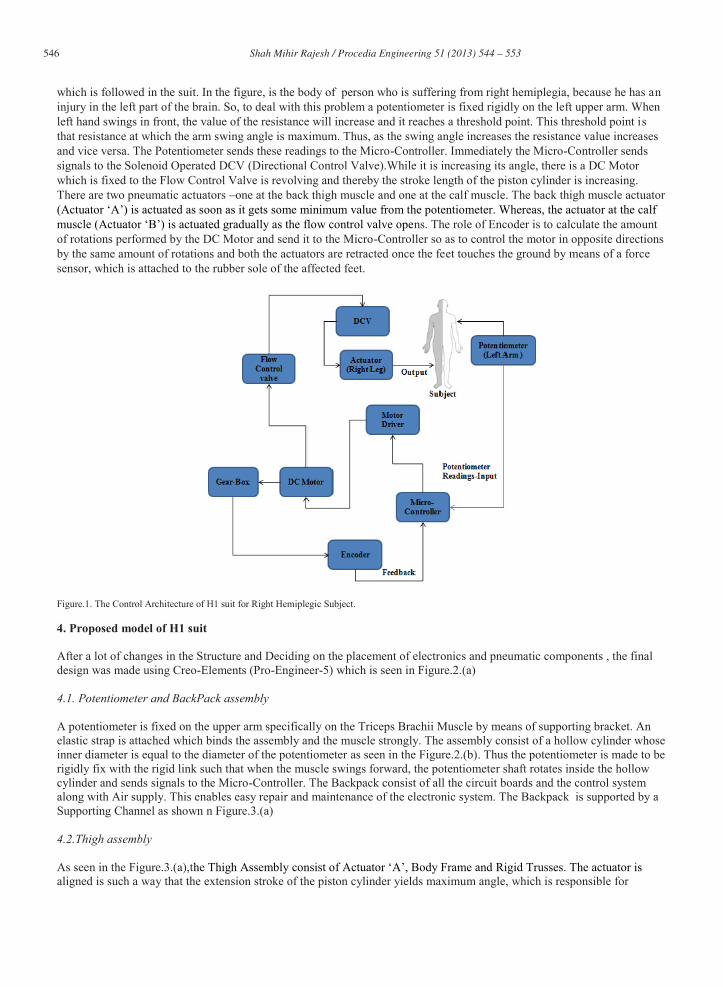
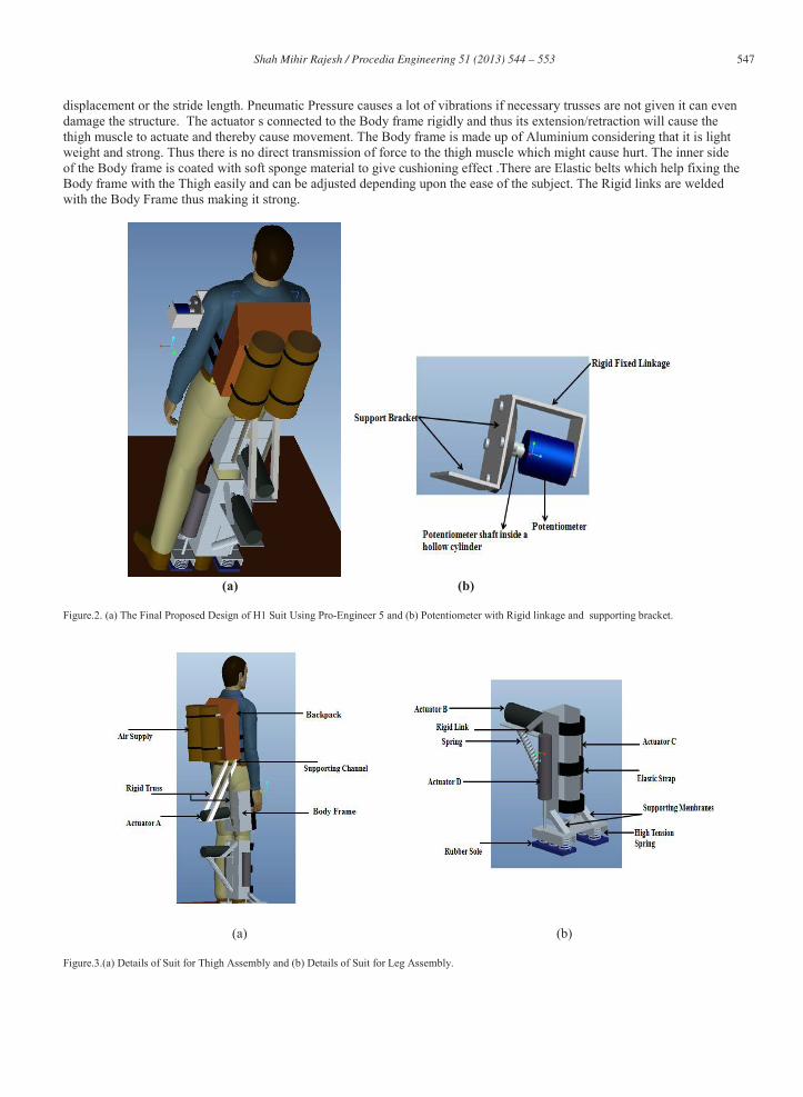
4. Proposed model of H1 suit After a lot of changes in the Structure and Deciding on the placement of electronics and pneumatic components , the final design was made using Creo-Elements (Pro-Engineer-5) which is seen in Figure.2.(a) 4.1. Potentiometer and BackPack assembly A potentiometer is fixed on the upper arm specifically on the Triceps Brachii Muscle by means of supporting bracket. An elastic strap is attached which binds the assembly and the muscle strongly. The assembly consist of a hollow cylinder whose inner diameter is equal to the diameter of the potentiometer as seen in the Figure.2.(b). Thus the potentiometer is made to be rigidly fix with the rigid link such that when the muscle swings forward, the potentiometer shaft rotates inside the hollow cylinder and sends signals to the Micro-Controller. The Backpack consist of all the circuit boards and the control system along with Air supply. This enables easy repair and maintenance of the electronic system. The Backpack is supported by a Supporting Channel as shown n Figure.3.(a) 4.2.Thigh assembly As seen in the Figure.3.(a),taligned is such a way that the extension stroke of the piston cylinder yields maximum angle, which is responsible for
547 Shah Mihir Rajesh / Procedia Engineering 51 ( 2013 ) 544 – 553
displacement or the stride length. Pneumatic Pressure causes a lot of vibrations if necessary trusses are not given it can even damage the structure. The actuator s connected to the Body frame rigidly and thus its extension/retraction will cause the thigh muscle to actuate and thereby cause movement. The Body frame is made up of Aluminium considering that it is light weight and strong. Thus there is no direct transmission of force to the thigh muscle which might cause hurt. The inner side of the Body frame is coated with soft sponge material to give cushioning effect .There are Elastic belts which help fixing the Body frame with the Thigh easily and can be adjusted depending upon the ease of the subject. The Rigid links are welded with the Body Frame thus making it strong.
(a) (b)
Figure.2. (a) The Final Proposed Design of H1 Suit Using Pro-Engineer 5 and (b) Potentiometer with Rigid linkage and supporting bracket.
(a) (b) Figure.3.(a) Details of Suit for Thigh Assembly and (b) Details of Suit for Leg Assembly.

548 Shah Mihir Rajesh / Procedia Engineering 51 ( 2013 ) 544 – 553
4.3. Leg assembly The Leg Assembly consists of Three Pneumatic actuators namely- Rubber Sole Mechanism, Rigid Trusses and Low Tension Spring as seen in Figure.3.(b) whole body frame will not travel in a linear motion due to the rigid links at the top of the body frame which is connected to the base of support of the cylinder and mainly due to low tension spring. As a result there will be a swing motion which is common Csupport the affected leg from the reaction forces. This allows movement of the subject in any uneven terrain also. Besides there is an elastic strap which facilitates strong binding between the Body frame and the Leg, which is adjustable. 5. Principle and Application of balance and weight shift to H1 5.1 .Concept of CG in balancing the body
distribution is called centre of gravity. Locating the centre of gravity by pivoting
located at the centre of their torso at about the height of the belly button . gravity will shift depending on the p CG rises a few inches when they raise their arms. The line of gravity is an imaginary vertical line that extends upwbalance if its centre of gravity is above its base of support [7].
(a) (b)
Figure.4. (a) Cylinders in different conditions when C.G is shifted [7] and (b) Two Cylinders with line of gravity passing through them [7]. For the two cylinders in Figure.4.(a) , of support so the upward reaction force from the base is aligned with the downward force due to weight. The cylinder on the right does not have force due to weight along the reaction force so these two forces cannot align and instead create a torque that rotates the object, tipping it over. The line of gravity helps to determine balance; if it passes through the base of support then the object is in balance. If the line of gravity touches the ground at a point outside the base of support then the object will tip over as in seen in Figure.4.(b). Standing upright, the base of support is the area under your feet (or shoes) including the area between your feet. This area is traced from toe to toe and from heel to heel. By moving your feet you can an increase or decrease the area of your base of support. The larger the base, the easier it is to keep centre of gravity above it and stay in balance.
Figure.5. A man walking by means of supporting cane [11]. In Figure.5, the left side picture Red markings shows the area under base of support of the subject and the Blue line shows the Line of Gravity whereas the right side picture shows the Top View and the shaded area of base of support.
549 Shah Mihir Rajesh / Procedia Engineering 51 ( 2013 ) 544 – 553
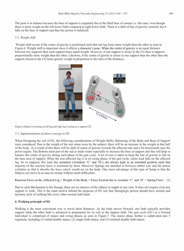
The pose is in balance because the base of support is expanded due to the third base of contact i.e. the cane, even though there is more weight on the left lower limb compared to right lower limb. There is a shift of line of gravity certainly but it falls on the base of support and thus the person is balanced. 5.2. Weight shift Weight shift occurs if the centre of gravity is positioned such that one leg bears more weight than the other as seen in Figure.6. Weight shift is important since it affects a is an equal distance between two supports then each support bears equal weight. However, if one support is closer to the CG then it supports proportionally more weight than the other. Likewise, if the centre of gravity is closer to one support than the other then the support closest to the CG bears greater weight in proportion to the ratio of the distances.
Figure.6.Subject is leaning on left leg and right leg is acting as a support [7]. 5.3. Implementation of above concept to H1 When Designing the suit of H1, the following considerations of Weight Shifts, Balancing of the Body and Base of Support were considered. Due to the weight of the suit when worn by the subject, there will be an increase in the weight at that half of the body. As a result of this there will be shift of centre of gravity towards the affected side and a bit downwards near the pelvis region. The Bottom most part of the suit is made wider especially to increase the base of support and this will help to balance the centre of gravity during each phase of the gait cycle. A lot of care is taken to keep the line of gravity to fall on the base area of support. When the non-affected leg is in its swing phase of the gait cycle, entire load falls on the affected leg. So to suppress this load majority of the reaction force is sustained by them. Moreover Springs are attached in between rubber sole and the piston cylinders so that it absorbs the force which would act on the body. One more advantage of this type of Setup is that the Subject can move in an uneven terrain without much difficulties.
(1) Due to such Mechanism in the Design, there are no chances of the subject to topple in any case. It does not require even any support to walk. This is the main motive behind the proposal of H1 suit that Hemiplegic person should have normal and dynamic style of walking like every other normal individual.
6. Walking principle of H1 Walking is the most convenient way to travel short distances. As the body moves forward, one limb typically provides support while the other limb is advanced in preparation for its role as the support limb. The gait cycle (GC) in a Normal Individual is comprised of stance and swing phases as seen in Figure.7. The stance phase further is subdivided into 3 segments, including (1) initial double stance, (2) single limb stance, and (3) terminal double limb stance.
550 Shah Mihir Rajesh / Procedia Engineering 51 ( 2013 ) 544 – 553
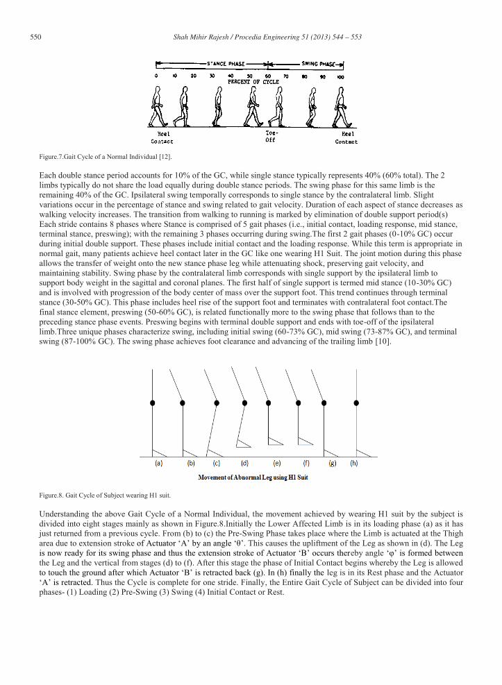
Figure.7.Gait Cycle of a Normal Individual [12]. Each double stance period accounts for 10% of the GC, while single stance typically represents 40% (60% total). The 2 limbs typically do not share the load equally during double stance periods. The swing phase for this same limb is the remaining 40% of the GC. Ipsilateral swing temporally corresponds to single stance by the contralateral limb. Slight variations occur in the percentage of stance and swing related to gait velocity. Duration of each aspect of stance decreases as walking velocity increases. The transition from walking to running is marked by elimination of double support period(s) Each stride contains 8 phases where Stance is comprised of 5 gait phases (i.e., initial contact, loading response, mid stance, terminal stance, preswing); with the remaining 3 phases occurring during swing.The first 2 gait phases (0-10% GC) occur during initial double support. These phases include initial contact and the loading response. While this term is appropriate in normal gait, many patients achieve heel contact later in the GC like one wearing H1 Suit. The joint motion during this phase allows the transfer of weight onto the new stance phase leg while attenuating shock, preserving gait velocity, and maintaining stability. Swing phase by the contralateral limb corresponds with single support by the ipsilateral limb to support body weight in the sagittal and coronal planes. The first half of single support is termed mid stance (10-30% GC) and is involved with progression of the body center of mass over the support foot. This trend continues through terminal stance (30-50% GC). This phase includes heel rise of the support foot and terminates with contralateral foot contact.The final stance element, preswing (50-60% GC), is related functionally more to the swing phase that follows than to the preceding stance phase events. Preswing begins with terminal double support and ends with toe-off of the ipsilateral limb.Three unique phases characterize swing, including initial swing (60-73% GC), mid swing (73-87% GC), and terminal swing (87-100% GC). The swing phase achieves foot clearance and advancing of the trailing limb [10].
Figure.8. Gait Cycle of Subject wearing H1 suit.
Understanding the above Gait Cycle of a Normal Individual, the movement achieved by wearing H1 suit by the subject is divided into eight stages mainly as shown in Figure.8.Initially the Lower Affected Limb is in its loading phase (a) as it has just returned from a previous cycle. From (b) to (c) the Pre-Swing Phase takes place where the Limb is actuated at the Thigh area due to extension stroke . This causes the upliftment of the Leg as shown in (d). The Leg
eby angle the Leg and the vertical from stages (d) to (f). After this stage the phase of Initial Contact begins whereby the Leg is allowed
leg is in its Rest phase and the Actuator . Thus the Cycle is complete for one stride. Finally, the Entire Gait Cycle of Subject can be divided into four
phases- (1) Loading (2) Pre-Swing (3) Swing (4) Initial Contact or Rest.
551 Shah Mihir Rajesh / Procedia Engineering 51 ( 2013 ) 544 – 553
7. Test Case
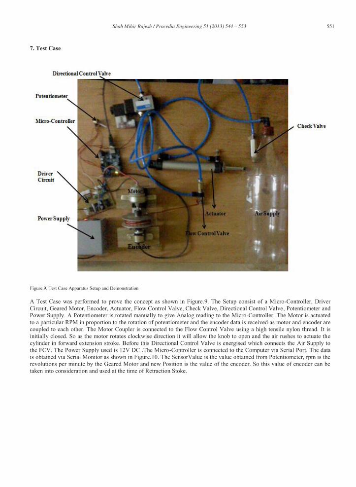
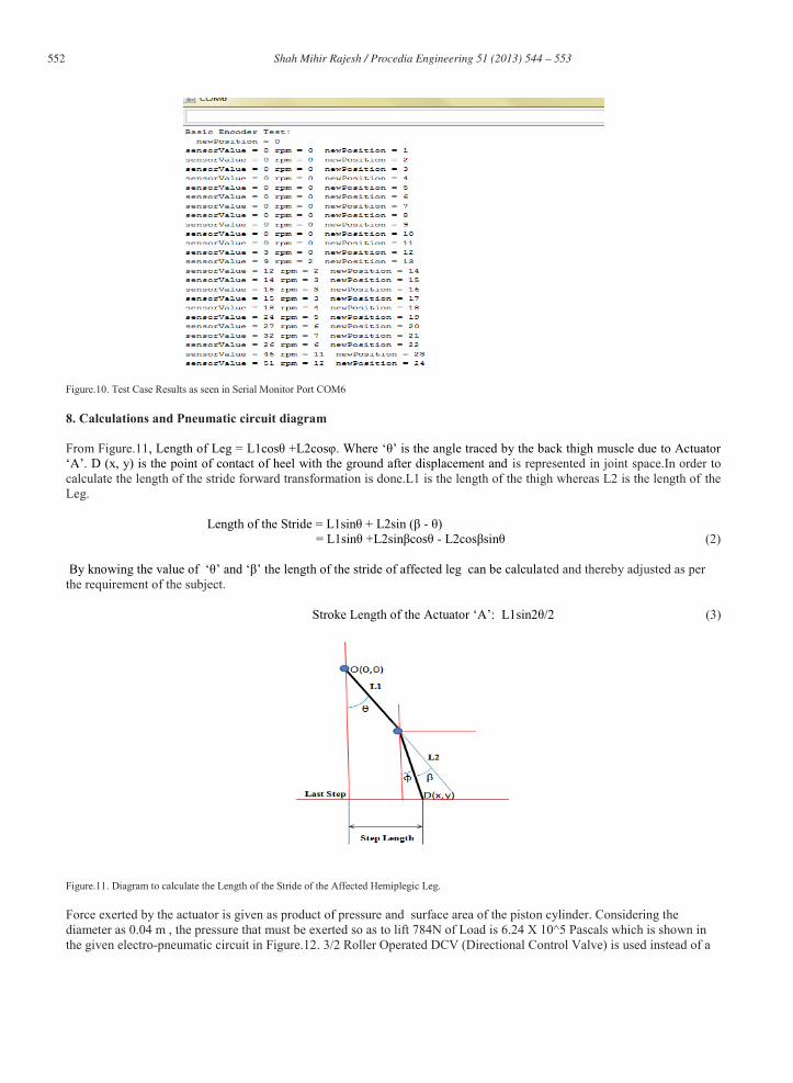
Figure.9. Test Case Apparatus Setup and Demonstration A Test Case was performed to prove the concept as shown in Figure.9. The Setup consist of a Micro-Controller, Driver Circuit, Geared Motor, Encoder, Actuator, Flow Control Valve, Check Valve, Directional Control Valve, Potentiometer and Power Supply. A Potentiometer is rotated manually to give Analog reading to the Micro-Controller. The Motor is actuated to a particular RPM in proportion to the rotation of potentiometer and the encoder data is received as motor and encoder are coupled to each other. The Motor Coupler is connected to the Flow Control Valve using a high tensile nylon thread. It is initially closed. So as the motor rotates clockwise direction it will allow the knob to open and the air rushes to actuate the cylinder in forward extension stroke. Before this Directional Control Valve is energised which connects the Air Supply to the FCV. The Power Supply used is 12V DC .The Micro-Controller is connected to the Computer via Serial Port. The data is obtained via Serial Monitor as shown in Figure.10. The SensorValue is the value obtained from Potentiometer, rpm is the revolutions per minute by the Geared Motor and new Position is the value of the encoder. So this value of encoder can be taken into consideration and used at the time of Retraction Stoke.
552 Shah Mihir Rajesh / Procedia Engineering 51 ( 2013 ) 544 – 553
Figure.10. Test Case Results as seen in Serial Monitor Port COM6
8. Calculations and Pneumatic circuit diagram From Figure.11
is represented in joint space.In order to calculate the length of the stride forward transformation is done.L1 is the length of the thigh whereas L2 is the length of the Leg. -
- (2)
ted and thereby adjusted as per the requirement of the subject.
(3)
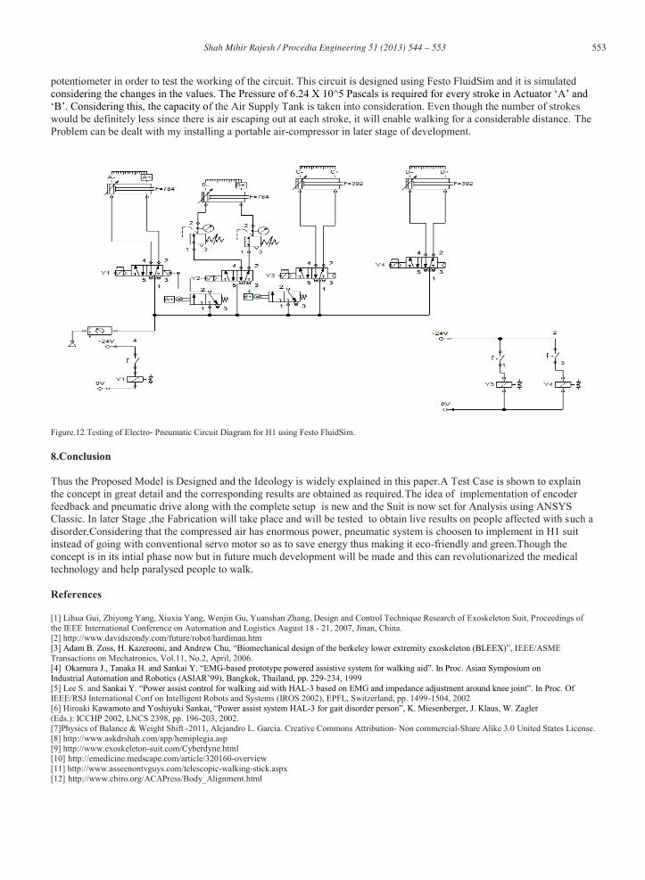
Figure.11. Diagram to calculate the Length of the Stride of the Affected Hemiplegic Leg. Force exerted by the actuator is given as product of pressure and surface area of the piston cylinder. Considering the diameter as 0.04 m , the pressure that must be exerted so as to lift 784N of Load is 6.24 X 10^5 Pascals which is shown in the given electro-pneumatic circuit in Figure.12. 3/2 Roller Operated DCV (Directional Control Valve) is used instead of a
553 Shah Mihir Rajesh / Procedia Engineering 51 ( 2013 ) 544 – 553
potentiometer in order to test the working of the circuit. This circuit is designed using Festo FluidSim and it is simulated
f the Air Supply Tank is taken into consideration. Even though the number of strokes would be definitely less since there is air escaping out at each stroke, it will enable walking for a considerable distance. The Problem can be dealt with my installing a portable air-compressor in later stage of development.
Figure.12.Testing of Electro- Pneumatic Circuit Diagram for H1 using Festo FluidSim. 8.Conclusion Thus the Proposed Model is Designed and the Ideology is widely explained in this paper.A Test Case is shown to explain the concept in great detail and the corresponding results are obtained as required.The idea of implementation of encoder feedback and pneumatic drive along with the complete setup is new and the Suit is now set for Analysis using ANSYS Classic. In later Stage ,the Fabrication will take place and will be tested to obtain live results on people affected with such a disorder.Considering that the compressed air has enormous power, pneumatic system is choosen to implement in H1 suit instead of going with conventional servo motor so as to save energy thus making it eco-friendly and green.Though the concept is in its intial phase now but in future much development will be made and this can revolutionarized the medical technology and help paralysed people to walk. References [1] Lihua Gui, Zhiyong Yang, Xiuxia Yang, Wenjin Gu, Yuanshan Zhang, Design and Control Technique Research of Exoskeleton Suit, Proceedings of the IEEE International Conference on Automation and Logistics August 18 - 21, 2007, Jinan, China. [2] http://www.davidszondy.com/future/robot/hardiman.htm
EEE/ASME Transactions on Mechatronics, Vol.11, No.2, April, 2006.
- -234, 1999
[5] Lee S. and -IEEE/RSJ International Conf on Intelligent Robots and Systems (IROS 2002), EPFL, Switzerland, pp. 1499-1504, 2002 [6] Hiroaki K - (Eds.): ICCHP 2002, LNCS 2398, pp. 196-203, 2002. [7]Physics of Balance & Weight Shift -2011, Alejandro L. Garcia. Creative Commons Attribution- Non commercial-Share Alike 3.0 United States License. [8] http://www.askdrshah.com/app/hemiplegia.asp [9] http://www.exoskeleton-suit.com/Cyberdyne.html [10] http://emedicine.medscape.com/article/320160-overview [11] http://www.asseenontvguys.com/telescopic-walking-stick.aspx [12] http://www.chiro.org/ACAPress/Body_Alignment.html