design of flexible spot welding cell for body-in-white
TRANSCRIPT

Periodicals of Engineering and Natural Sciences ISSN 2303-4521
Vol.6, No.2, October 2018, pp. 24~38
Available online at: http://pen.ius.edu.ba
DOI: 10.21533/pen.v6i2.180 24
Design of flexible spot welding cell for
Body-In-White (BIW) assembly
Sadasivam Narayanan
1, M. Elangovan
2, Prabha Shankar
3 M. Thenarasu
2
1 Whirlpool of India Limited, Pune, Maharashtra, India 2Department of Mechanical Engineering, Amrita School of Engineering, Coimbatore, Amrita Vishwa Vidyapeetham, India
33D Concept Analysis & Development (India) Pvt Ltd, Bangalore, India
Article Info ABSTRACT
Article history:
Received Aug 2, 2018
Revised Oct 16, 2018
Accepted Oct 19, 2018
In this paper, a flexible spot welding cell - which is flexible both at
fixture and work cell level is developed to handle multiple Body-In-
White (BIW) part varieties. The work-cell is a human-robot
cooperative cell where the operator loads/unloads the parts on one side,
whereas the robot concurrently performs welding operation on other
side. The fixture is made modular and is reconfigured for change in
part varieties. The flexibility of proposed work cell and fixture are
investigated and validated by considering two different BIW spot weld
assemblies. The performance of robot, cycle time estimation for the
process, checking of fixtures, collision detection between weld gun and
fixtures are evaluated in virtual environment. The flexible weld cell is
proved to be compatible for both the BIW assemblies considered for
study. The proposed concept shorten the design & fabrication time of
fixture - squeezing the investment cost, assembly cost and floor space;
besides reducing the cycle time and improving the robot utilization by
30% - 40% when compared to the conventional method.
Keyword:
Body-In-White
Robotic simulation
Virtual manufacturing
Modular welding fixture
Flexible manufacturing
system
Corresponding Author:
Dr. M. Elangovan,
Department of Mechanical Engineering,
Amrita School of Engineering, Coimbatore,
Amrita Vishwa Vidyapeetham, India.
Email: [email protected]
1. Introduction
Welding is predominantely used in automobile industries and requirements for fixtures that ease the welding
process is a continuous development task in any industry [1] and [2]. Many reserachers have contributed to
the study on welding parameters required in solid state welding, ultrasonic welding, fricition welding,
resistannce welding, spot welding etc., [3] and [4], but there have been very few studies related to modular
fixtures used for welding that contribute towards productivity
Car Body-In-White (BIW) is a complicated steel-structure including 300~500 sheets with complex shape and
are assembled by means of welding in a high rhythm through 55~75 robotic work-stations [5]. Typically a
robotic welding station includes: a robot equipped with weld gun; control system for robot, welding
equipment and auxiliary devices if any, welding fixture to hold the car panels in desired position in-spite of
thermal distortions. Today’s market is constantly pressurizing the automobile companies to offer customers
more choice of products and variants in shorter lead time, demanding lower production costs. To fulfill these
evidently conflicting requirements, a single station or cell must be able to handle a mix of different models
without calling for a total re-design of its equipments. The key solution to this challenge lies with Flexible

Narayanan et al. PEN Vol. 2, No. 2, 2018, pp. 24 – 38
25
Manufacturing System (FMS) which is “The ability of a manufacturing system to adapt to changes in
environmental conditions and in the process requirements” [6].
The flexibility of a BIW spot welding cell critically depend on the level of flexibility at both - work cell
(macro scale) and fixture (micro scale) levels. In other words, the work cell must be able to handle a mix of
models & offer greater productivity and at the same time the fixture must be compatible for holding multiple
part varieties.
1.1. Flexible solutions for work cell
Several Flexible solutions for Body-In-White assembly work-cells have been proposed to improve
productivity and enhance application to a diverse range of products. Reference [7] have developed flexible
programmable positioners and a new cell control concept for handling modularity and flexibility - where car
model specific and geometrically fixed toolings for fixtures and grippers will be replaced by flexible tooling
using "Programmable and lean positioners". The proposed FlexLean concept allows designing highly flexible
automotive body assembly lines for a changing mix of different models in the same line, but it demands huge
investment and maintenance.
A new cell production assembly system with human–robot cooperation is presented in [8]. This system
consists of three key technologies - parts feeding by double manipulators on a mobile base, production process
information support for the operator, and safety management for cooperation between the operator and the
robot. The proposed cell holds good for assembling small or medium sized parts; whereas BIW assembly
demands a more robust system.
In the former one, the automation level is too high for the small or medium level enterprises to afford, whereas
the latter proposed concept is not robust for automotive applications. Here arise the need to develop robust,
cost effective solutions for BIW spot welding applications for a small or medium enterprise level to meet low
volume production where multiple part varieties are to be handled.
1.2. Flexible solutions for fixtures
Coming to fixtures, one of the indispensible elements in manufacturing - be it assembly, welding, machining,
inspection and testing. A fixture performs the duty of locating, holding and supporting the work-piece during
a manufacturing operation and arrests the degree of freedom of the job in all the six directions. A weld fixture
does all the aforesaid duties, besides reducing the distortion on work-piece due to the development of heat and
residual stress during welding operation. These fixtures influence the product quality, productivity and cost in
a manufacturing system.
Welding fixtures are the prerogative work holding devices for BIW assembly in automobile and aerospace
industries. Typically the weld fixtures are made rigid - to suit the requirements of a single assembly. The
design and fabrication cost of fixture can amount to 10% - 20% of the total cost of a manufacturing system
[9]. Also the fixture design work is a tiresome and time taking process. It depends mainly on the knowledge
and/or experience of the fixture design engineer; generally it demands over 10 years of practice to design
quality fixtures [10]. Therefore design fabrication and installation of new fixtures in the plant requires long
lead time. And when there is a change in part variety, the old fixture must be replaced with a new one, which
is a time, cost and space consuming tradition. Thence in order to reduce the manufacturing cost and remain
competitive in the market, fixturing technique must emerge to permit reconfiguration both in the design and
usage of fixtures.
Several flexible solutions for fixtures have been proposed. Evolution of reconfigurable welding fixtures is a
significant development for the highly competitive automotive industry. Rapid launch of new vehicle models
and variants can be facilitated by adopting reconfigurable welding fixtures, which can be adjusted to locate
and clamp parts of dissimilar shapes and sizes [11], [12] and [13]. Reference [14] classified the fixtures as
dedicated fixtures and general purpose fixtures (reconfigurable, conformable and modular fixtures) based on
its flexibility. The most important and widest used general purpose flexible fixtures are modular fixtures due
to its performance on easy usage, versatility and its adaptability to product changes.
Reference [15] have described how to use UGNX and Computer Aided Design Technology to carry out
automotive welding line fixture design from the following three aspects which include standardization,
modularization and software secondary development. Standardization includes universal parts standardization
and private parts standardization; modularization includes parts modularization and fixture unit

Narayanan et al. PEN Vol. 2, No. 2, 2018, pp. 24 – 38
26
modularization; software secondary development includes automatically generating two-dimensional map
frame, details column of two-dimensional assembly drawing and automatically generating technology
requirement of fixture parts.
Reference [16] have developed a cost-effective reconfigurable welding assembly fixture system for parts with
similar characteristics of automotive body, including modular mechanism, online detection and adaptive
control system The reconfigurable fixture developed by him uses an adaptive control device for accurate
fixturing of car panels; but the online detection and adaptive control system will push the fixture cost up.
Modular tooling is the key to achieve flexibility at fixture level. Modular fixtures are gaining popularity in the
industry, and there are quite a number of firms providing modular fixturing solutions across globe. They can
widely accommodate various changes of work-pieces in shape, size, and process, etc. But they are more
suitable for general fixturing applications with medium level accuracy. Automotive body assembly process is
a multi-station assembly process to fabricate the structural frame of an automobile body, where typically
involves joining of several hundred sheet metal parts to form a body-in-white. BIW assembly demands high
level of fixturing accuracy as any error can cause product dimensional problem, resulting in low quality and
poor performance of BIW.
Thus in order to develop an economic, accurate solution for BIW modular fixturing, a custom library of
fixture elements with varying sizes must be developed.
1.3. Robotic Simulation
Computer simulation palys an important role in analyzing engineering problems [17], [18], and [19]. In the
past 2 decades, finite element anlaysis (FEA) has become an increasingly useful tool for the prediction of the
stress [20], [21] and [22]. Here simulation is used to study the validating the strength of the fixture. Robotic
simulation tools like ROBCAD, IGRIP have replaced traditional techniques and have become inevitable in
process simulation because of their rapid, accurate calculations which saves huge amount of time and money.
Reference [23] introduced virtual design in the body welding line, discusses the feature and key technique of
designation in the Virtual Manufacturing & Assembling environment, points out the virtual design is the
direction of body welding line in China.
The weld cell and fixtures developed were to be validated for its compatibility to handle multiple part varieties
in virtual environment using such simulation tools.
Based on the detailed literature review, the purpose of this study is laid-out as follow:
(a) To develop flexible solutions for improving productivity at work cell level for small or medium level BIW
assembly environments with low production volume but high part varieties.
(b) To provide flexible, cost effective, modular solutions for fixtures to make them compatible for handling
multiple part varieties.
(c) To simulate the working of work cell and fixtures in virtual environment and check for its compatibility to
handle multiple part varieties.
2. Selection of Car Parts
In this study, the flexibility of proposed work cell and fixture are investigated by considering two different
spot weld assemblies. Primarily, the front door inner panel and side bracket of GM sedan car are to be spot
welded as shown in Figure 1. The previously spot welded inner panel assembly is then welded with the cross
bracket as shown in Figure 2. The work cell and modular fixture designed must be compatible for both the
assemblies to be spot welded.

Narayanan et al. PEN Vol. 2, No. 2, 2018, pp. 24 – 38
27
Fig. 1. Spot weld part details for Assembly - I
Fig. 2. Spot weld part details for Assembly - II
Weld spots for each weld assembly are highlighted in Figure 1 and 2 as WP1, WP2, WP3 and so on. Weld
points are the locations on which spot welding will be carried out on the automobile sheet metal components.
The Weld points form the base for fixture design, the clamping plan & locating plan are done based on the
weld spot distribution.
3. Modular Welding Fixture
Modular fixtures are very popular in industry, and there are quite a number of firms providing modular
fixturing solutions across the globe. They can widely accommodate various changes of work-pieces in shape,
size, and process, etc. But they are more suitable for general fixturing applications with medium level
accuracy. Automotive body assembly process is a multi-station assembly process to fabricate the structural
frame of an automobile body, which typically involves joining of several hundred sheet metal parts to form a
Body-In-White. BIW assembly demands high level of fixturing accuracy as any error can cause product
dimensional problem, resulting in low quality and poor performance of BIW. The fixture design is carried out
using SolidWorks, CAD tool.
3.1. Modular fixture part library
Unlike rigid fixture, the elements of fixture are divided into multiple modules that can be adjusted in all the
three translational ways (along X, Y and Z) , so the modules can be moved and adjusted to different locations
along all the three directions to accommodate multiple part varieties. This is achieved by building the modules
with regularly pitched holes. But problem arise, if the module need to be moved a distance lesser than the
pitch of the hole. This issue is solved by providing spacers along X, Y and Z of each module whose thickness
is custom-made per the need. Besides this, the NC blocks & holders that hold the car panels must have the
profile of the car panel. Thus these parts are made newly for each BIW car panel that needs to be fixtured.
Thus, the part library created has two broad groups:
Standard parts - Designer chooses parts from this library to build fixture.

Narayanan et al. PEN Vol. 2, No. 2, 2018, pp. 24 – 38
28
Custom designed parts - Designer has the freedom to modify the part size based on the need.
3.2. Fixture design for Assembly - I
The foremost step taken before starting the design of welding fixture is to arrive at the spot weld locations.
The location and orientation of other critical units of the fixture including clamps, locators etc., are decided
based on the weld spot distribution. The weld spots for Front door inner panel - side bracket assembly are
located as shown in Table 1 with respect to the body line of car.
Table 1. Weld Point Distribution for assembly - I
3.2.1. Locator (PLP) plan
Principal Locating Points (PLP) are the points at which the car panels are to be located onto the fixture. The
welding fixture is designed with locator units to aid the operator to load the car panels onto the fixture at the
right location and orientation. The locator unit consists mainly of locating pin, Pin retainer, L block, Spacers
and/or shims, Riser, Riser spacer. Minimum two locators units are provided to locate the car parts properly
onto the fixture.
3.2.2. Clamp plan
Toggle clamps hold the car part firmly and prevent the part from distortion while carrying out the spot
welding operation. A single clamping unit consists of the following parts:
a. Finger: Finger is a movable part which is used to hold the Car part from top against the Back-up and they
are usually mounted on the clamp arm.
b. L-Block: L - Shaped blocks (single or in combination) used to mount the finger to clamp arm, besides
allowing adjustment for locator pin in two directions.
c. Shim and spacer: They allow the finger to be moved to the correct XYZ locating and / or allow the
customer to make adjustments to improve the quality of their product.
d. Blade: Part onto which the aforesaid elements are attached to.
e. Blade spacer: It allows the finger to be moved to the correct location along one direction.
f. Riser: L- shaped tall block with regularly patterned holes to attach the above mentioned parts in modular
way Blade space.
Weld Point Distribution
WP
#
Co-ordinates (In mm)
X Y Z
1 464.00 780.00 536.00
2 464.00 780.00 521.00
3 477.00 810.00 395.00
4 477.00 810.00 268.00
5 472.50 810.00 149.50
6 487.00 755.00 270.00
7 463.00 736.00 640.50

Narayanan et al. PEN Vol. 2, No. 2, 2018, pp. 24 – 38
29
g. Riser spacer: Plate with regularly patterned holes to mount the riser. The entire assembly is then screwed
to the main base plate of the fixture.
3.2.3. Rough locator plan:
Rough locators are elements that aid the operator to guide the car panels while loading onto the fixture and ensure a fool-proof assembly. The overall dimensions and isometric view of Fixture - I are as shown in Figure 3.
Fig. 3. Overall dimensions of Fixture - I
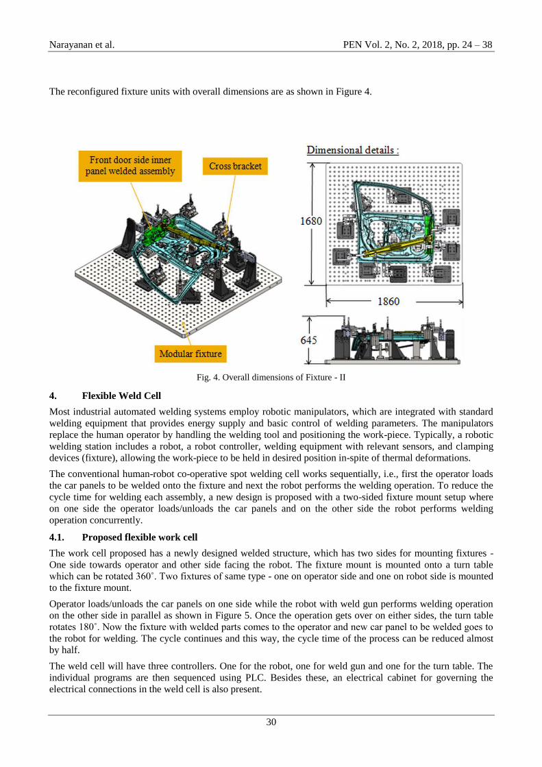
3.2.4. Fixture design for Assembly - II
The previously spot welded Front door inner panel - side bracket assembly is added with one more cross
bracket in Assembly - II. The modular fixture developed for assembly-I is reconfigured and redesigned for
spot welding assembly - II. The weld spot locations with respect to the body line of car are as shown in Table
2.
Table 2: Weld point distribution for assembly - II
Weld Point Distribution
WP # Co-ordinates (In mm)
X Y Z
1 1366.00 798.04 168.22
2 1399.90 799.18 155.22
3 1379.26 798.91 85.69
4 1321.33 797.05 95.02
5 456.16 836.71 360.20
6 456.35 837.50 330.90
Narayanan et al. PEN Vol. 2, No. 2, 2018, pp. 24 – 38
30
The reconfigured fixture units with overall dimensions are as shown in Figure 4.
Fig. 4. Overall dimensions of Fixture - II
4. Flexible Weld Cell
Most industrial automated welding systems employ robotic manipulators, which are integrated with standard
welding equipment that provides energy supply and basic control of welding parameters. The manipulators
replace the human operator by handling the welding tool and positioning the work-piece. Typically, a robotic
welding station includes a robot, a robot controller, welding equipment with relevant sensors, and clamping
devices (fixture), allowing the work-piece to be held in desired position in-spite of thermal deformations.
The conventional human-robot co-operative spot welding cell works sequentially, i.e., first the operator loads
the car panels to be welded onto the fixture and next the robot performs the welding operation. To reduce the
cycle time for welding each assembly, a new design is proposed with a two-sided fixture mount setup where
on one side the operator loads/unloads the car panels and on the other side the robot performs welding
operation concurrently.
4.1. Proposed flexible work cell
The work cell proposed has a newly designed welded structure, which has two sides for mounting fixtures -
One side towards operator and other side facing the robot. The fixture mount is mounted onto a turn table
which can be rotated 360˚. Two fixtures of same type - one on operator side and one on robot side is mounted
to the fixture mount.
Operator loads/unloads the car panels on one side while the robot with weld gun performs welding operation
on the other side in parallel as shown in Figure 5. Once the operation gets over on either sides, the turn table
rotates 180˚. Now the fixture with welded parts comes to the operator and new car panel to be welded goes to
the robot for welding. The cycle continues and this way, the cycle time of the process can be reduced almost
by half.
The weld cell will have three controllers. One for the robot, one for weld gun and one for the turn table. The
individual programs are then sequenced using PLC. Besides these, an electrical cabinet for governing the
electrical connections in the weld cell is also present.

Narayanan et al. PEN Vol. 2, No. 2, 2018, pp. 24 – 38
31
Fig. 5. Proposed weld cell concept
4.2. Fixture mount design
The two sided fixture mount is a welded structure. Three different design iterations are carried out for fixture
mount and the best one is chosen based on the ergonomics for operator loading, simplicity and a stronger
design that can withstand the payload of fixtures. The chosen design is as shown in Figure 6. The Frame
mount designed must be having good strength to take the payload of fixtures acting on either side. Though the
structure is completely welded, a static Finite Element Analysis is carried out using SolidWorks Simulation to
validate the design for structural rigidity.
Fig. 5. Proposed weld cell concept
4.2.1. Finite Element Analysis
To intent of the analysis is to study the behavior of the welded frame when loaded with fixtures with pay load
of 1700 kg approx on each side. Among the two fixtures designed, the one with maximum weight is
considered for analysis as a worst case scenario as shown in Figure 6.

Narayanan et al. PEN Vol. 2, No. 2, 2018, pp. 24 – 38
32
Fig. 6. Finite Element Analysis set-up
Initial, Loading and boundary conditions are defined in the model. The meshed model is as shown in Figure 7.
Mesh type: Solid
Element type: Tetrahedral
Element size: 20mm
Tolerance: 1 mm
Mesh quality: High
Total Nodes: 677516
Total Elements: 388186
Fig.7. Meshed model of the fixture mount structure
The stress, strain and displacement plots obtained from the analysis are studied for the structural strength. The
Factor of Safety of the design obtained is approximately 3; Excess Factor of Safety is kept intentionally as the
modular fixture weight is bound to increase when it is reconfigured for car panels larger than parts chosen for
study.
4.2.2. Selection of weld cell components
Proper selection of three weld cell equipments - Turn table, Weld gun and welding robot are critical. The turn
table is selected considering the factor that is must withstand the axial load exerted by the fixture units and
frame mount. The right one is chosen after performing a hand calculation to find out the payload acting on the
turn table.
For spot welding, the guns normally include a pneumatic or hydraulic cylinder and are designed to fit a
particular assembly. The most common are C-type and X-type guns, which differ in shape and force
application mechanisms (in the first case, the cylinder is connected directly to the moving electrode; in the
second case, it is connected via the lever arm). However, some new welding guns incorporate built-in
electromechanical servo actuators with MFDC supply for force generation. The selection of weld gun depends
on the process parameters to be used for spot welding. Weld gun for our application is chosen from ARO, a
renowned welding equipments supplier across globe. The right spot welding robot is chosen from FANUC
library based on the pay load of weld gun, number of degree of freedom for the robot and its reachability.
5. Robotic Simulation
Before the use of computer simulation, layout and research studies were calculation-intensive tasks that
required a hard work. Manual calculations made multiple design iterations and work cell layout scenarios
difficult, time-consuming, and extremely expensive. Even that hard work does not ensure that the robot
AA AA-Enlarged View

Narayanan et al. PEN Vol. 2, No. 2, 2018, pp. 24 – 38
33
system works correctly, because a small calculation error could be disastrous. In fact, Robotic simulation and
Off-line Programming (OLP) can minimize, if not eliminate and required to program robotic cells manually.
5.1. Work cell with fixture - I
Robotic simulation for weld cell with fixture - I is done using IGRIP D5R17SP4 software package to verify
that the robot can reach all of the positions required to complete spot welding and that the robot and tool will
not collide with fixtures or other objects. Various steps adopted for simulating the weld cell in virtual
environment are as briefed below.
5.1.1. Creating part and assembly model in IGRIP
To create three - dimensional visual representation of part models, IGRIP CAD context is used. It has a world
Cartesian coordinate system that works as the common reference point for dimension measurements of part
models. The 3D CAD model, Fixtures or weld gun for instance are saved in Parasolid (*.X_T) format and are
then imported to IGRIP software. The files are then saved as Part model. IGRIP software has an in-built
library of robots of various brands with pre-defined specifications for distance, speed and joints.
5.1.2. Positioning device models in IGRIP layout
When a Device model is retrieved from IGRIP Device library and placed in the work cell, the Device model
first superposes on the world Cartesian coordinate system of the layout context. The device models are then
translated and rotated along different axes and positioned in the right location and orientation. Figure 8 shows
the flexible spot weld cell with all devices.
Fig. 8. Weld cell with fixture - I in IGRIP environment
5.1.3. Kinematics definition
Kinematics is defined for all the devices including turn table, moving elements of fixture including toggle
clamps, retractable pin units. Type of each joint, speed and acceleration for each joint are specified.
5.1.4. Robot reachability check
Robot is then checked for reach-ability with the fixture, and made sure that it can reach all weld spots with-in
the translational and rotational limits for the joints.
5.1.5. Weld spot and device motion definition
The weld spots are defined on the prescribed locations as shown in Figure 9. The axis of weld spot along
welding direction must be normal to the weld surface. To ensure this, the weld spot co-ordinates are created
using "SURFACE" option under Tags in Layout menu.

Narayanan et al. PEN Vol. 2, No. 2, 2018, pp. 24 – 38
34
In the IGRIP layout, the motion destination position of a Device model is represented by a tag point in a
Cartesian coordinate frame with N, O, and A (or X, Y and Z) axes. To calculate the position of a tag point in
the layout, it is attached to a part model. With the attachment, the position of a tag point can be determined
with respect to the base coordinate system of the Part model to which the tag point is attached. In the database,
all tag points in the layout are stored with different names.
Fig. 9. Weld co-ordinates for assembly - I
Figure 10 shows the various tag points and path for the robot to perform spot welding operation.
Fig. 10. Tag points and weld path to spot weld assembly - I
5.1.6. Sequencing of devices
If we have one or more Device models and we want to program; the behavior of each model in the work cell
can be simulated over time. Instructions for each device are coded by giving Sequences. The sequence defines
the motion, manipulation and action of the devices. Based on the distance of each tag point from home
position, motion type, speed and acceleration – one can obtain cycle time for each device assigned with
sequences. This way robot cycle time is precisely calculated. After sequencing all the devices, a simulation is
run with "collision check" ON and made sure that the welding operation is collision free.
5.2. Work cell with fixture - II
The work cell is replaced by fixture two to check the compatibility of the work cell equipments for welding
multiple parts. The simulation steps remain same as explained earlier. The weld co-ordinates and weld path
defined for spot welding assembly II are as shown in Figure 11 and 12 respectively.

Narayanan et al. PEN Vol. 2, No. 2, 2018, pp. 24 – 38
35
Fig. 11. Weld co-ordinates for assembly - II
Fig. 11. Tag points and weld path to spot weld assembly - II
Instructions for each device are fed as sequences. Robot cycle time for spot welding assembly - II is calculated
based on the device parameters set.
6. Results and Discussions
6.1. Modular fixture
The modular fixture developed is proved to have the ability to get reconfigured for securing multiple BIW
parts. Figure 12 and 13 show the modular fixture in two configurations for securing two different BIW car
part assembly.

Narayanan et al. PEN Vol. 2, No. 2, 2018, pp. 24 – 38
36
Fig. 12. Modular fixture for assembly - I
Fig. 13. Reconfigured modular fixture for assembly - II
6.2. Simulation results
The robot cycle time for welding BIW assembly - I (Front door inner panel and side bracket) is precisely
found as 42.2 seconds from Simulation. Similarly, the robot cycle time for welding BIW assembly -II (Front
door inner panel assembly and cross bracket) is precisely found as 51.35 seconds.

Narayanan et al. PEN Vol. 2, No. 2, 2018, pp. 24 – 38
37
The efficiency of newly developed work cell for BIW assembly - I and II are compared with the conventional
work cell in-terms of cycle time, robot utilization and number of components it can produce per shift as shown
in Table 3 and 4 respectively.
Table 3 Conventional Vs Flexible cell comparison for assembly – I
Table 4 Conventional Vs Flexible Cell comparison for assembly - II
7. Conclusion
In this work, a flexible spot weld cell with modular fixture is developed to accommodate multiple BIW part
varieties of medium size without re-designing or changing the entire system. Two car BIW assemblies were
considered for evaluating the flexibility. A library of modular fixture parts was created and the fixtures were
designed by choosing the parts from the library. Unlike rigid fixtures, the modular tool can be reconfigured for
change in part varieties. The modular fixture designed is proved to be reconfigurable for both the BIW
assemblies considered for the study. Thereby, it saves huge amount of time, efforts and money in design and
fabrication of the fixtures.
The flexible spot weld cell was introduced with a two-sided fixture mount structure mounted onto a turn table.
The strength of fixture mount is validated using Finite Element Analysis and is found to have a Factor Of
Safety (FOS) of 3. Unlike conventional method, this weld cell with two fixtures assist concurrent
manufacturing and reduces cycle time. The weld cell with both fixtures was simulated in virtual environment
using IGRIP D5. The performance of robot, cycle time estimation for the process, checking of fixtures,
collision detection between weld gun and fixtures are done in Robotic Simulation and the weld cell is proved
to be compatible for both the car BIW assemblies considered for study. The proposed flexible concept reduces
cycle time and improves robot utilization by 30% - 40% when compared to the conventional method.
8. Acknowledgment
This study was supported by 3D Concept Analysis & Development India Private Limited and the authors
would like to thank all the others who supported the authors.
9. References
[1] Sanga, B., Wattal, R., & Nagesh, D. S. Mechanism of Joint Formation and Characteristics of Interface
in Ultrasonic welding: Literature Review. Periodicals of Engineering and Natural Sciences
(PEN), vol. 6-1, pp.107-119, 2018.
S.No Parameters Conventional
method
Flexible
method
1 Total cycle time (sec) 92.2 56
2 Robot utilization 45% 75%
3 No of components for
single shift 293 482
S.No Parameters Conventional
method
Flexible
method
1 Total cycle time (sec) 106.3 59
2 Robot utilization 50% 90%
3 No of components for
single shift 254 458

Narayanan et al. PEN Vol. 2, No. 2, 2018, pp. 24 – 38
38
[2] Akca, E., and Gürsel, A. Solid state welding and application in aeronautical industry. Periodicals of
Engineering and Natural Sciences (PEN), vol 4-1, pp.1-8, 2016.
[3] Akca, E., and Gürsel, A. The importance of interlayers in diffusion welding- A review. Periodicals
of Engineering and Natural Sciences (PEN), vol 3-2, pp.12-16, 2015.
[4] Kicukov, E., and Gursel, A. Ultrasonic welding of dissimilar materials: A review. Periodicals of
Engineering and Natural Sciences (PEN), vol 3-1, pp 28-36, 2015
[5] Dong,W., Hui Li, and Xiaoting T. "Off-line programming of Spot-weld Robot for Car-body in
White Based on Robcad," In Mechatronics and Automation, 2007. ICMA 2007. International
Conference on, pp. 763-768. IEEE, 2007.
[6] De Toni, A. and Tonchia, S, “Manufacturing flexibility: a literature review,” International journal
of production research, vol. 36-6, pp.1587-1617, 1998
[7] Soetebier, S, Muller,C., Mauser,N., Kock,S. and Legeleux,F. "Flexible automation for automotive
body assembly," In Automation Science and Engineering, 2008. CASE 2008. IEEE International
Conference on, pp. 341-346. IEEE, 2008.
[8] Morioka, M., and Shinsuke S. "A new cell production assembly system with human– robot
cooperation," CIRP annals, vol. 59-1, pp. 9-12, 2010.
[9] Bi Zm, Zhang Wj. "Flexible fixture design and automation: review, issue and future
directions." International Journal of Production Research, vol. 39-13, pp. 2867-2894, 2001.
[10] Rong, Yiming Kevin, and Huang.S. “Advanced computer-aided fixture design,” Elsevier, 2005.
[11] Verbrugge, M. W., Jihui Yang, Yang T. Cheng, Michael J. Lukitsch, Alan L. Browne, and Nilesh
D. Mankame. "Reconfigurable fixture device and methods of use." U.S. Patent 7,480,975, issued
January 27, 2009.
[12] Jones, S. D. "Computer controlled reconfigurable part fixture mechanism." U.S. Patent 5,732,194,
issued March 24, 1998.
[13] Nelson, P. E., and Hugh R.S. "Reconfigurable holding fixture." U.S. Patent 5,249,785, issued
October 5, 1993.
[14] Wang, Hui, Yiming Kevin Rong, Hua Li, and Price Shaun. "Computer aided fixture design: Recent
research and trends." Computer-Aided Design, vol. 42-12, pp. 1085-1094, 2010
[15] Tong, Guiying, and Xiaomei Shao. "Application of CAD Techniques in Design of Automobile Body
Welding Line." In Measuring Technology and Mechatronics Automation (ICMTMA), 2011 Third
International Conference on, vol. 1, pp. 523-527, 2011.
[16] Jialiang, Z, Yang,J., and Beizhi Li. "Development of a reconfigurable welding fixture system for
automotive body." In Reconfigurable Mechanisms and Robots, 2009. ReMAR 2009.
ASME/IFToMM International Conference on, pp. 736-742, 2009.
[17] Mohanavelu, T., R. Krishnaswamy, and K. Marimuthu Prakash. "Simulation Modeling and
Development of Analytic Hierarchy Process (AHP) based Priority Dispatching Rule (PDR) for a
Dynamic Press Shop." International Journal of Industrial and Systems Engineering, vol 27-3, pp.
340-364, 2017.
[18] SathishKumar,V.R., Anbuudayasankar,S.P and Thenarasu.M. "Design and development of
simulation based model to rank job flow strategies." ARPN Journal of Engineering and Applied
Sciences, vol.11-9, pp.6082-6086, 2006.
[19] Durakovic, B., and Torlak, M. Simulation and experimental validation of phase change material and
water used as heat storage medium in window applications. J. of Mater. and Environ. Sci, 8(5), 1837-
1746, 2017
[20] Bora, C. B., Emek, S., Evren, V., & Bora, Ş. Modeling and Simulation of the Resistance of Bacteria
to Antibiotics. Periodicals of Engineering and Natural Sciences (PEN), vol 5-3, pp 396-408, 2017
[21] Turkmen, A. C. Autonomous Car Parking System with Various Trajectories. Periodicals of
Engineering and Natural Sciences (PEN), vol 5-3, pp 364-370, 2017
[22] Akca, E. (2016). Validation of stresses with numerical method and analytical method. Periodicals of
Engineering and Natural Sciences (PEN), vol 4-1, pp.17-28, 2016.
[23] Xiong, Xiaoping, and Quandong Jin. "The Design of Body Welding Line Base on the Virtual
Manufacturing and Assembling Environment." In Applied Computing, Computer Science, and
Advanced Communication, pp. 150-156. Springer, Berlin, Heidelberg, 2009.