design of deployable helical antennas for space-based...
TRANSCRIPT

Proceedings of Emerging Sensing Technologies Summit 2018
Design of Deployable Helical Antennas forSpace-Based Automatic Identification SystemReception
Geoffrey Knott1 ID , Andrew Viquerat1,∗ ID and Alexe Bojovschi2
1 Department of Mechanical Engineering Sciences, University of Surrey, Guildford, GU2 7XH, UnitedKingdom; [email protected] (G.K.)
2 International Innovation Research Network, Melbourne, Australia; [email protected]* Correspondence: [email protected]; Tel.: +44-(0)1483-686-267
Abstract: Communications present a major bottleneck for small-satellite functionality giventheir extremely small volumes and low power. This work addresses this gap by presentingan ultra-compact, high-gain deployable helical antenna designed for space-based reception ofAutomatic Identification System signals at 162 MHz for maritime surveillance. The radio frequencycharacteristics of helically curved ribbons are investigated and optimized through a parametric studyof the helical and ground plane geometry. Square, planar ground planes of various size and thickness,and a range of helical ribbon widths are studied. Both are modeled as perfect electrical conductorsusing ANSYS High Frequency Structure Simulator. Simulation results indicate that the addition of aground plane centered and positioned at the base of the helical antenna element: 1) reduces back loberadiation and 2) enables optimization of the radiative performance through adjusting the antennageometry i.e. the peak gain may be increased by 3.5% (on average) for each additional helical turn —1-8 helical turns are simulated. The half-power beam width may also be improved indefinitely byadding more helical turns. The most focused beam presented, 40 deg, is produced by an 8-turn helix,which is 58 cm in diameter and has an axial length of 3.68 m. Two ground plane sizes are considered,with the largest, which is four times larger in area, producing 5% higher peak gain. Conversely, theground plane size had negligible effect on the half-power beam width in long helices (i.e. >3 helicalturns). Increasing the helical ribbon width in steps of 10 mm was found to improve the peak gain by8% on average in long helices.
Keywords: automatic identification system, helical, antenna, satellite, communication
1. Introduction
In recent years extremely small satellites have been developed in response to trends in the spaceindustry to achieve more for less cost. By the turn of the millennium, the ‘CubeSat’ marked theculmination of this development enabling low-cost opportunities and ushering a new era in spaceexperimentation [1]. A CubeSat is a cube-shaped satellite of sides 10 cm and less than 1 kg in mass,contrasting markedly to conventional satellites that are on the order of several meters and hundreds, ifnot thousands, of kilograms. Miniaturization, increased capability and very low power consumptionelectronics proved revolutionary to the semiconductor, computer and consumer electronics industriesand it is intended to be as disruptive to the space industry.
Space presents multiple valuable benefits for Earth observation including forecasting the weather,assessing environmental hazards and most importantly, global coverage. However, communicationsremain a major bottleneck for CubeSat functionality [2]. CubeSats require compact deployable solutionsgiven their extremely small volume and low power that restricts the size and types of antenna availablefor use. Typically, monopole and dipole antennas are used for telemetry and data transmission. Theseomnidirectional antennas operate around 146 MHz for uplink, and 437 MHz for downlink and producelow-gain characteristics (maxima of 2.06 dB and 3.35 dB, respectively [3]) providing poor data rates on

2 of 9
the order of Kbps. Data rates a thousand times greater on the order of Mbps are required for multimediadownload. High-gain antennas enable sensitive and low power communication systems. Low powerconsumption is crucial given the few Watts of available power in a CubeSat. Good sensitivity isimportant for applications where the incoming signals are weak e.g. Automatic Identification System(AIS) signals.
Utilizing the latest advances in composite materials and multi-functional deployable structuresresearch [4], this paper presents a novel deployable helical antenna concept for enhanced space-basedAutomatic Identification System (S-AIS) receivers. The proposed small-satellite subsystem in Figure 1comprises of a 10 cm x 10 cm x 10 cm cube housing five co-coiled bistable composite slit tubes (BCSTs).BCSTs are stiff and lightweight open-section tubular structures that can be rolled-up and deployed,analogous to a tape measure but without the need of any constraint to remain stowed [5]. Embeddedwithin each of the straight and helical BCSTs are monopole and helical antennas, respectively. Inaddition to providing deployability and omnidirectional communications, the straight BCSTs supporta gossamer ground plane for improved radio frequency (RF) characteristics i.e. gain and directionality,and to minimize backlobes of the helical antenna.
Figure 1. Conceptualized small-satellite S-AIS receiver comprising of straight and helical embeddeddeployable antennas, and gossamer ground plane.
The paper is organized as follows: Section 2 outlines the helical antenna design theory andsimulation approach used, and an example of RF results and their interpretation; Section 3 presents RFsimulation results (i.e. the peak gain, half-power beam width and reflection coefficient versus numberof helical turns, ground plane size and thickness and helical ribbon width); Section 4 evaluates theeffectiveness of each antenna parameter for optimizing the RF characteristics.
2. Method
The helical antenna investigated in this work is designed for receiving S-AIS signals in axial modeat 162 MHz and based on Kraus’ formulas [6]. These formulas estimate the antenna peak gain anddirectionality, presented in (1)-(5), and highlight the large size antenna required for operation at suchlow frequencies e.g. AISat [7,8]. In the literature these formulas have been shown as too optimistic [9]whilst those from Emerson in (A1) [10] are too pessimistic and those empirically derived by Wong &King in (A2) & (A3) [11] lying in-between Kraus’ and Emerson’s estimations. As a result of the rangein predicted effects of helical geometry on RF characteristics, these additional formulas are plotted in
3 of 9
the RF results for comparison — the formulas are shown in Appendix A. The Kraus design equationsfor an axial mode helical antenna [6] are,
C = λ = 1.85 m (1)
S =λ
4= 0.46 m (2)
R =λ
2π= 0.29 m (3)
where C is the helical circumference, S is the spacing between each turn of helix, and R is the helicalradius. A 7-turn helical antenna is modeled (N = 7) that is predicted to produce a peak gain (G, ameasure of efficiency) and half-power beam width (HPBW, a measure of directionality) of:
G = 10.8 + 10 log(
NC2Sλ3
)= 13.2 dBi (4)
HPBW =52
C
√λ3
NS= 39.4 (5)
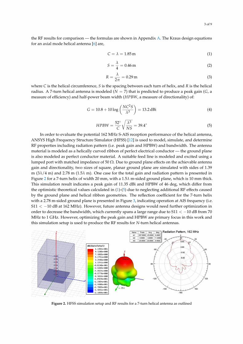
In order to evaluate the potential 162 MHz S-AIS reception performance of the helical antenna,ANSYS High Frequency Structure Simulator (HFSS) [12] is used to model, simulate, and determineRF properties including radiation pattern (i.e. peak gain and HPBW) and bandwidth. The antennamaterial is modeled as a helically curved ribbon of perfect electrical conductor — the ground planeis also modeled as perfect conductor material. A suitable feed line is modeled and excited using alumped port with matched impedance of 50 Ω. Due to ground plane effects on the achievable antennagain and directionality, two sizes of square, planar ground plane are simulated with sides of 1.39m (3λ/4 m) and 2.78 m (1.5λ m). One case for the total gain and radiation pattern is presented inFigure 2 for a 7-turn helix of width 20 mm, with a 1.5λ m-sided ground plane, which is 10 mm thick.This simulation result indicates a peak gain of 11.35 dBi and HPBW of 46 deg, which differ fromthe optimistic theoretical values calculated in (1)-(5) due to neglecting additional RF effects causedby the ground plane and helical ribbon geometries. The reflection coefficient for the 7-turn helixwith a 2.78 m-sided ground plane is presented in Figure 3, indicating operation at AIS frequency (i.e.S11 < −10 dB at 162 MHz). However, future antenna designs would need further optimization inorder to decrease the bandwidth, which currently spans a large range due to S11 < −10 dB from 70MHz to 1 GHz. However, optimizing the peak gain and HPBW are primary focus in this work andthis simulation setup is used to produce the RF results for N-turn helical antennas.
Figure 2. HFSS simulation setup and RF results for a 7-turn helical antenna as outlined

4 of 9
S11
(dB)
Frequency (MHz)100 200 300 400 500 600 700 800 900 1000
0
-10
-20
-30
-40
-50
-60
-70
-80
-90
-100
70 MHz
Figure 3. Reflection coefficient, S11, versus frequency for a 7-turn helix. A square ground plane of sides2.78 m and helical ribbon width of 20 mm is modeled
3. Results
The RF result for a helical antenna without ground plane is presented in Figure 4. RF simulationresults for four helical antennas with square, planar ground planes with sides 3λ/4 and 1.5λ m, andthickness 10 and 2 mm are presented in Figure 5 — predictions from the literature [6,10,11] are included.The helical antenna is modeled as a helically curved ribbon with the RF simulation results for variousribbon widths (i.e. 10, 20, 30, 40, and 50 mm) presented in Figure 6. The antenna reflection coefficientsversus frequency for each ribbon width are presented in Figure 7.
4. Discussion
The radiation pattern produced by a helical antenna without ground plane achieves low gain andpoor directionality (i.e. large HPBW) as shown in Figure 4. The standalone 7-turn helix produces tworadiation lobes oriented along the helical axis, along the ‘Z’ axis where ‘Theta’ equals zero and 180degrees. The largest of these lobes is back-facing and exhibits a peak gain of 3.7 dBi, and a very largeHPBW of 172 deg. Such a HPBW would be too high for effective targeted sensing applications such asS-AIS signals reception. The radiation pattern and peak gain are relatively constant and independentfrom the number of helical turns.
Figure 4. HFSS simulation setup and RF radiation pattern of a helical antenna without ground plane
5 of 9
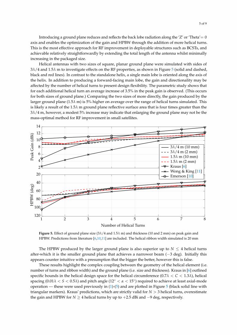
Introducing a ground plane reduces and reflects the back lobe radiation along the ‘Z’ or ‘Theta’= 0axis and enables the optimization of the gain and HPBW through the addition of more helical turns.This is the most effective approach for RF improvement in deployable structures such as BCSTs, andachievable relatively straightforwardly by extending the total length of the antenna whilst minimallyincreasing in the packaged size.
Helical antennas with two sizes of square, planar ground plane were simulated with sides of3λ/4 and 1.5λ m to investigate effects on the RF properties, as shown in Figure 5 (solid and dashed,black and red lines). In contrast to the standalone helix, a single main lobe is oriented along the axis ofthe helix. In addition to producing a forward-facing main lobe, the gain and directionality may beaffected by the number of helical turns to present design flexibility. The parametric study shows thatfor each additional helical turn an average increase of 3.5% in the peak gain is observed. (This occursfor both sizes of ground plane.) Comparing the two sizes of more directly, the gain produced by thelarger ground plane (1.5λ m) is 5% higher on average over the range of helical turns simulated. Thisis likely a result of the 1.5λ m ground plane reflective surface area that is four times greater than the3λ/4 m, however, a modest 5% increase may indicate that enlarging the ground plane may not be themass-optimal method for RF improvement in small satellites.
Peak
Gai
n(d
Bi)
HPB
W(d
eg)
Number of Helical Turns
1 2 3 4 5 6 7 8
14
12
10
8
6
4
2
20
40
60
80
100
120
3λ/4 m (10 mm)3λ/4 m (2 mm)1.5λ m (10 mm)1.5λ m (2 mm)Kraus [6]Wong & King [11]Emerson [10]
Figure 5. Effect of ground plane size (3λ/4 and 1.5λ m) and thickness (10 and 2 mm) on peak gain andHPBW. Predictions from literature [6,10,11] are included. The helical ribbon width simulated is 20 mm
The HPBW produced by the larger ground plane is also superior up to N ≤ 4 helical turnsafter-which it is the smaller ground plane that achieves a narrower beam (−3 deg). Initially thisappears counter intuitive with a presumption that the bigger the better, however this is false.
These results highlight the complex coupling between the geometry of the helical element (i.e.number of turns and ribbon width) and the ground plane (i.e. size and thickness). Kraus in [6] outlinedspecific bounds in the helical design space for the helical circumference (0.7λ < C < 1.3λ), helicalspacing (0.01λ < S < 0.5λ) and pitch angle (12 < α < 15) required to achieve at least axial-modeoperation — these were used previously in (1)-(5) and are plotted in Figure 5 (black solid line withtriangular markers). Kraus’ predictions, which are strictly valid for N > 3 helical turns, overestimatethe gain and HPBW for N ≥ 4 helical turns by up to +2.5 dBi and −9 deg, respectively.

6 of 9
Although the generally pessimistic peak gain formula from Emerson [10] is strictly valid for2 < L/λ < 7 and S/λ = 0.24, where L/λ is the axial length of the helix in wavelengths, the paralleltrend in the range 4 ≤ N ≤ 8 (i.e. the solid black line with circular markers) consistently over-predictsthe gain by +0.71 and +1.19 dBi for the 1.5λ and 0.75λ m ground planes, respectively. (For clarification,the helical turns considered in this work, 1 ≤ N ≤ 8, equate to 0.25 ≤ L/λ ≤ 2.) This factor couldbe readily adjusted in A1 for better predictions, however, the original formula is presented in thiscase. The peak gain results converge to Emerson’s predictions, which can be explained by the latter’sassumption of an infinitely sized ground plane.
The complexity of antenna design with specific consideration of the ground plane is underlinedfurther by Djordjevic in [13] who showed that a square ground plane of sides 1.5λ m could outperforman infinite one in terms of maximizing the average peak gain over the frequency range considered(i.e. 1.2-2.2 GHz). The empirically derived formulas from Wong & King [11] (i.e. solid black lineswith ‘x’ markers) are based on helical antennas operating in the 650-1,100 MHz frequency range, with5 ≤ N ≤ 35 helical turns, 5 mm-diameter copper tubing and a high circular cavity rather than aconventional ground plane. Although these formulas will not be valid for the antennas designedin this work for 162 MHz and with square, planar ground planes — this is particularly apparent incomparing the peak gain values — the HPBW predicted by Wong & King closely match with a minordiscrepancy of −1.46 deg.
Two ground plane thicknesses (10 and 2 mm) are also presented in Figure 5, which are simulatedto investigate the effects of using extremely thin material for the envisaged reflective membrane. (Theground plane must be very thin, typically less than 1 mm, for ultra-compact folding and stowage insidea small satellite.) The results show that particularly for N ≥ 5 helical turns (>10.5 dBi) the groundplane thickness has negligible effect on gain. Furthermore, the HPBW is relatively unaffected by theground plane thickness for N ≥ 4 turns. These results provide confidence in using thin materials forthe ground plane that both minimize mass and maximize stowed-to-deployed volume ratio withoutcompromising the RF characteristics.
Further RF improvements may be achieved by increasing the width of the helical ribbon as shownin Figure 6. The helical ribbon widths simulated are 10-50 mm, in steps of 10 mm. Firstly, the resultsconfirm that increasing the number of helical turns significantly improves the peak gain and HPBW.The RF results for N ≤ 3 and N ≥ 3 helical turns exhibit increases in the peak gain to various degrees.It is observed that for short helices with N ≤ 3 helical turns, expanding the ribbon width in steps of10 mm produces a modest 2% increase in peak gain on average. Comparing the peak gain producedby long helical antennas (i.e. 3 ≤ N ≤ 8 turns) with ribbon widths of 10 and 50 mm, the peak gain isimproved more significantly by 8% on average, indicating that increasing the ribbon width is far moreeffective in long helical antennas (i.e. N ≥ 3). The greatest peak gain increase is observed at N = 8helical turns for 10 to 50 mm ribbon width, from 11.23 to 12.52 dBi, representing an increase of 11.5%.Figure 7 confirms that the antennas continue to operate at each helical ribbon width due to S11 < −10dB at 162 MHz.
It has been established that the HPBW decreases with the number of helical turns as the main lobeis enhanced and narrowed. This is essential for directional antenna, or targeted, sensing applications.The HPBW rapidly improves for N < 3 turns, with much shallower and constant narrowing for N > 3turns (Figure 6). The HPBW may be decreased indefinitely by increasing the number of turn and/orribbon width. In these simulations the lowest HPBW is 40 deg for N = 8 helical turns and 50 mmribbon width.
5. Conclusions
A deployable helical antenna is presented and its RF properties investigated through a parametricstudy of the helical and ground plane geometry. Mass-optimal approaches for optimizing the RFperformance are identified. The antenna structure is envisaged to be manufactured using bistable

7 of 9
1 2 3 4 5 6 7 885807570656055504540
8.59
9.510
10.511
11.5
12.512
13Pe
akG
ain
(dBi
)
Number of Helical Turns
HPB
W(d
eg)
50 mm40 mm30 mm20 mm10 mm
Figure 6. Effect of helical ribbon width on gain and HPBW. A ground plane thickness of 1 mm issimulated
10 mm
20
0
-20
-40
-60
-80
-100
-12050 100 150 200 250 300
S11
(dB)
Frequency (MHz)
20 mm30 mm40 mm50 mm
Figure 7. Effect of helical ribbon width on the reflection coefficient, S11
composite to enable extremely compact stowage. Conducting material such as copper shall beembedded to provide the radiative element.
Further work is required for RF simulations of helical tubes to investigate additional geometricallydependent RF effects. This is achievable by introducing cross-sectional curvature into the helicallycurved ribbons modeled thus far. Additionally, due to the deployment method of the helical antennaelement, the helix may in practice be positioned off-center with respect to the center of the groundplane — this shall be considered in future for quantifying affects on the main lobe direction and
8 of 9
magnitude. This could be addressed using appropriate feed lines. Addressing these two points maybetter represent the RF characteristics of the helical tube antenna architecture envisaged.
The square gossamer ground plane architecture presented here comprises of four distinctquadrants. Therefore, addition investigations are required to identify the consequences segmentingthe ground plane may incur on RF performance. Furthermore, parabolic ground planes may beinvestigated for enhanced gain and HPBW, which can enable more compact ground planes to achievecomparable RF properties to planar, square architectures.
Finally, given that the helical copper ribbon considered thus far is an element embeddedwithin a helical composite structure, incorporating additional structural materials into the simulatedantenna such as carbon-fiber, may be considered to identify a potential source of RF interference oramplification.
Funding: This research was funded by the Engineering and Physical Sciences Council, UK Research andInnovation, grant number EP/R044902/1. Dr Geoffrey Knott thanks Dr Andrew Viquerat, the Faculty ofEngineering and Physical Sciences at the University of Surrey and organizers of the Emerging Sensing TechnologiesSummit (ESTS 2018), particularly Dr Alexe Bojovschi, for conference funding contributions.
Abbreviations
The following abbreviations are used in this manuscript:S-AIS space-based Automatic Identification SystemBCST bistable composite slit tubeRF radio frequencyAIS Automatic Identification SystemHPBW half-power beam widthHFSS High Frequency Structure SimulatorESTS Emerging Sensing Technologies Summit
Appendix A. Helical antenna design equations
The peak gain formula from Emerson [10] in units of dBi is,
GEmerson = 10.25 + 1.22Lλ− 0.0726
(Lλ
)2(A1)
where L/λ is the axial length of the helix in wavelengths, and the formulas from Wong & King [11],including HPBW in units of degrees, are,
GWong & King = 8.3(
πDλ
)√N+2+1 (NSλ
)0.8 [ tan 12.5tan α
]√N/2(A2)
HPBWWong & King =61.5
(2N
N+5
)0.6
(πDλ
)√N/4 (NSλ
)0.7
[tan α
tan 12.5
]√N/4(A3)
where D is the helical diameter (i.e. 2R), λ is the wavelength, N is the number of helical turns, S is thehelical spacing, and α is the helical pitch angle (i.e. S = πD tan α).
References
1. Heidt, H.; Puig-Suari, J.; Moore, A.S.; Nakasuka, S.; Twiggs, R.J. CubeSat: A new Generation of Picosatellitefor Education and Industry Low-Cost Space Experimentation. 14th Annual/USU Conference on SmallSatellites, 2000, pp. 1–19.

9 of 9
2. Muri, P.; Challa, O.; McNair, J. Enhancing Small Satellite Communication Through EffectiveAntenna System Design. The 2010 Military Communications Conference. IEEE, 2010, pp. 347–352.doi:10.1109/MILCOM.2010.5680405.
3. Schraml, K.; Narbudowicz, A.; Chalermwisutkul, S.; Heberling, D.; Ammann, M. Easy-to-deployLC-loaded dipole and monopole antennas for cubesat. 11th European Conference on Antennas andPropagation (EUCAP), 2017, pp. 2303–2306. doi:10.23919/EuCAP.2017.7928135.
4. Knott, G.; Viquerat, A. Helical bistable composite slit tubes. Composite Structures 2019, 207, 711–726.doi:10.1016/j.compstruct.2018.09.045.
5. Iqbal, K.; Pellegrino, S.; Daton-Lovett, A. Bi-stable Composite Slit Tubes. In Solid Mechanics and ItsApplications; Pellegrino, S.; Guest, S.D., Eds.; Springer, Dordrecht, 2000; chapter IUTAM-IASS Symposiumon Deployable Structures: Theory and Applications, pp. 153–162. doi:10.1007/978-94-015-9514-8_17.
6. Kraus, J., Ed. Antennas for all Applications, 3rd ed.; McGraw-Hill, Inc., 2003.7. Spröwitz, T.; Block, J.; Bäger, A.; Hauer, L.; Schütze, M. Deployment Verification of Large
CFRP Helical High-Gain Antenna for AIS Signals. IEEE Aerospace Conference Proceedings, 2011.doi:10.1109/AERO.2011.5747319.
8. Block, J.; Bäger, A.; Behrens, J.; Delovski, T.; Hauer, L.C.; Schütze, M.; Schütze, R.; Spröwitz, T.A self-deploying and self-stabilizing helical antenna for small satellites. Acta Astronautica 2013.doi:10.1016/j.actaastro.2011.10.012.
9. Djordjevic, A.R.; Zajic, A.G.; Ilic, M.M.; Stüber, G.L. Optimization of Helical Antennas. IEEE Antennas andPropagation Magazine 2006, 48, 107–116. doi:10.1109/MAP.2006.323359.
10. Emerson, D.T. THE GAIN OF THE AXIAL-MODE HELIX ANTENNA: A NUMERICAL MODELINGSTUDY.
11. Wong, J.L.; King, H.E. Empirical Helix Antenna Design. Antennas and Propagation Society InternationalSymposium, 1982, pp. 366–369. doi:10.1109/APS.1982.1148836.
12. ANSYS, Inc.. ANSYS Electromagnetics Suite 18.0.0, 2018.13. Djordjevic, A.R.; Zajic, A.G.; Ilic, M.M. Enhancing the Gain of Helical Antennas by Shaping the Ground
Conductor. IEEE Antennas and Wireless Propagation Letters 2006, 5, 138–140. doi:10.1109/LAWP.2006.873946.