design of cryogenic systems for advanced power plants using … · 2016-12-09 · design of...
TRANSCRIPT

Design of Cryogenic Systems for Advanced Power Plants using Simultaneous Heat Integration and Process Optimization
Alex Dowling, Cheshta Balwani & Larry Biegler
Carnegie Mellon University
AIChE 2014 November 20th, 2014

Motivation
Develop framework for full oxycombustion power plant optimization
– Estimate cost of electricity with carbon capture
– Balance trade-offs between systems
2
Oxycombustion Power Plant 1. Air Separation Unit 2. Boiler 3. Steam Turbines 4. Pollution Controls 5. CO2 Compression Train
1 2 3
4 5

Agenda 1. Framework for Equation Oriented
Flowsheet Optimization – Embedded pinch heat integration
2. Case Study: Air Separation Unit – Multistream heat exchanger design
3. Driving Force Calculations – Extension of pinch methods
4. Case Study: CO2 Process Unit
3
Thermodynamics &
Flash Calculations
Distillation Cascades Heat Integration
Complex Reactors (e.g. CFD)
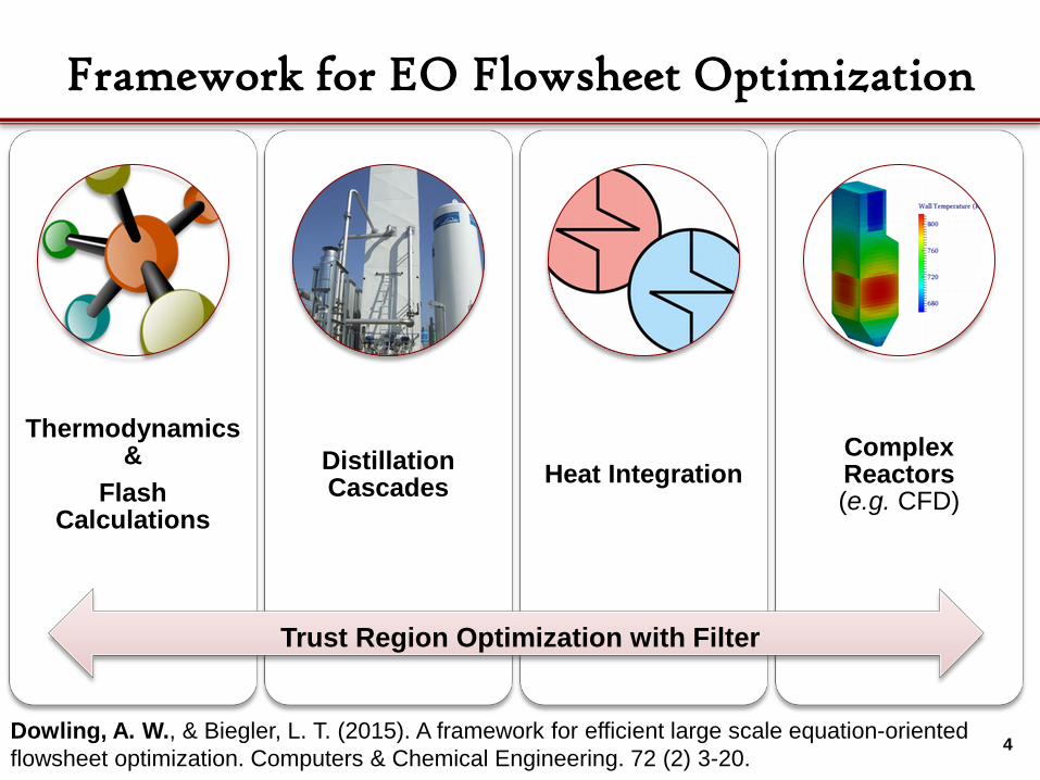
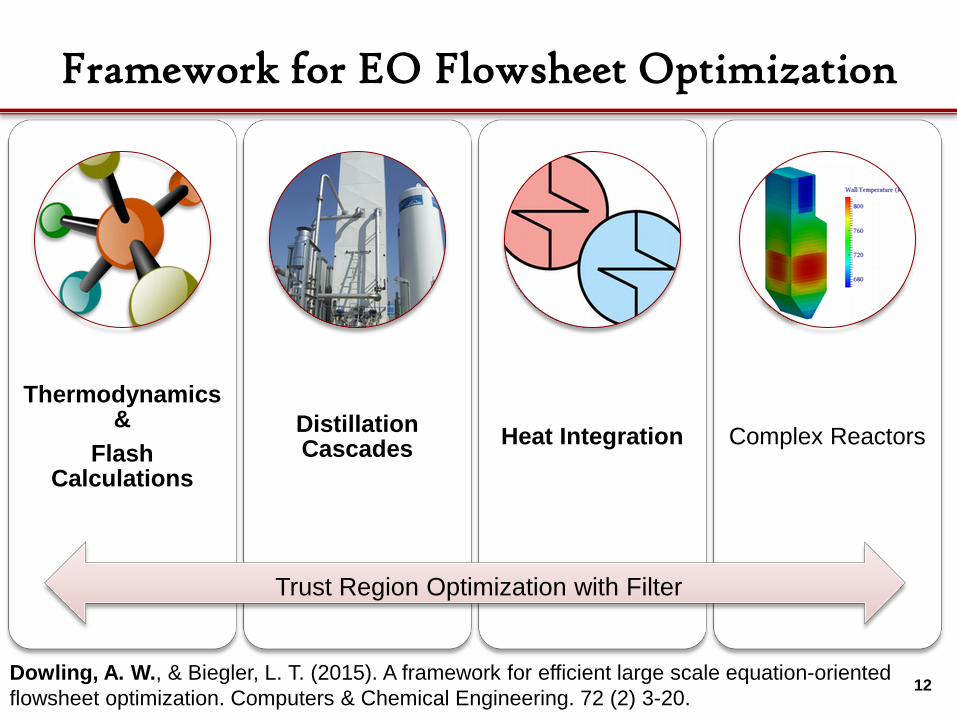
Framework for EO Flowsheet Optimization
4
Trust Region Optimization with Filter
Dowling, A. W., & Biegler, L. T. (2015). A framework for efficient large scale equation-oriented flowsheet optimization. Computers & Chemical Engineering. 72 (2) 3-20.

Thermodynamics &
Flash Calculations
Distillation Cascades Heat Integration Complex
Reactors
Framework for EO Flowsheet Optimization
5
Trust Region Optimization with Filter
Dowling, A. W., & Biegler, L. T. (2015). A framework for efficient large scale equation-oriented flowsheet optimization. Computers & Chemical Engineering. 72 (2) 3-20.
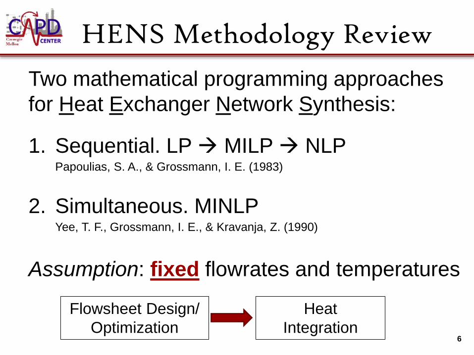
HENS Methodology Review
Two mathematical programming approaches for Heat Exchanger Network Synthesis:
1. Sequential. LP MILP NLP
Papoulias, S. A., & Grossmann, I. E. (1983)
2. Simultaneous. MINLP
Yee, T. F., Grossmann, I. E., & Kravanja, Z. (1990)
Assumption: fixed flowrates and temperatures
6
Flowsheet Design/ Optimization
Heat Integration
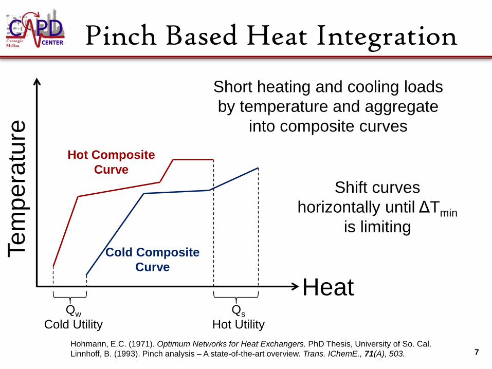
Pinch Based Heat Integration
7
Tem
pera
ture
Heat Qw
Cold Utility
Qs Hot Utility
Hot Composite Curve
Cold Composite Curve
Shift curves horizontally until ΔTmin
is limiting
Hohmann, E.C. (1971). Optimum Networks for Heat Exchangers. PhD Thesis, University of So. Cal. Linnhoff, B. (1993). Pinch analysis – A state-of-the-art overview. Trans. IChemE., 71(A), 503.
Short heating and cooling loads by temperature and aggregate
into composite curves
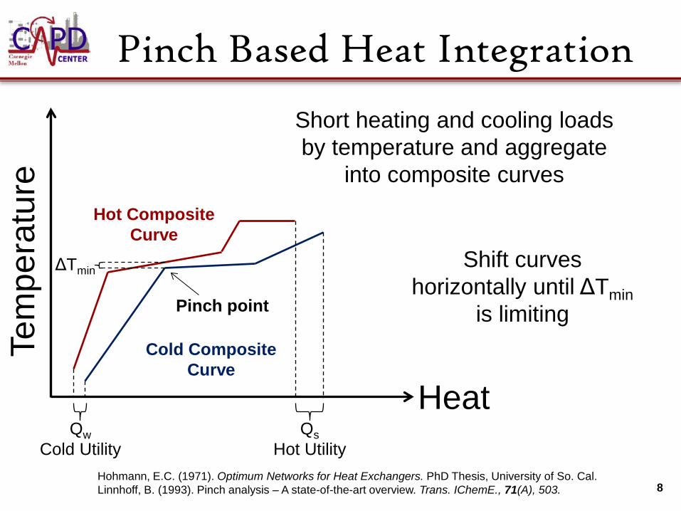
Pinch Based Heat Integration
8
Tem
pera
ture
Qw Cold Utility
Qs Hot Utility
ΔTmin
Hot Composite Curve
Cold Composite Curve
Shift curves horizontally until ΔTmin
is limiting Pinch point
Hohmann, E.C. (1971). Optimum Networks for Heat Exchangers. PhD Thesis, University of So. Cal. Linnhoff, B. (1993). Pinch analysis – A state-of-the-art overview. Trans. IChemE., 71(A), 503.
Heat
Short heating and cooling loads by temperature and aggregate
into composite curves

Duran-Grossmann Formulation
9
Pinch candidates Available heating and cooling above pinch Utility calculations
Flowsheet Optimization
Heat Integration
Duran, M. A., & Grossmann, I. E. (1986). Simultaneous optimization and heat integration of chemical processes. AIChE Journal, 32(1), 123–138.

Comments on DG
1. Algebraic form of the pinch method
2. Temperature intervals and stream ordering not assumed a prior
3. Discrete decisions (ordering) accommodated with smoothed max
10

Heat Exchanger Decomposition
11
2-phase
vapor
liquid
Q
T
HX3 HX2
HX1
Decomposition for Validation
2-phase
vapor
liquid
Q
T
HX3b
HX2b & HX2a
HX3a HX1b HX1a
Thermodynamics &
Flash Calculations
Distillation Cascades Heat Integration Complex Reactors
Framework for EO Flowsheet Optimization
12
Trust Region Optimization with Filter
Dowling, A. W., & Biegler, L. T. (2015). A framework for efficient large scale equation-oriented flowsheet optimization. Computers & Chemical Engineering. 72 (2) 3-20.
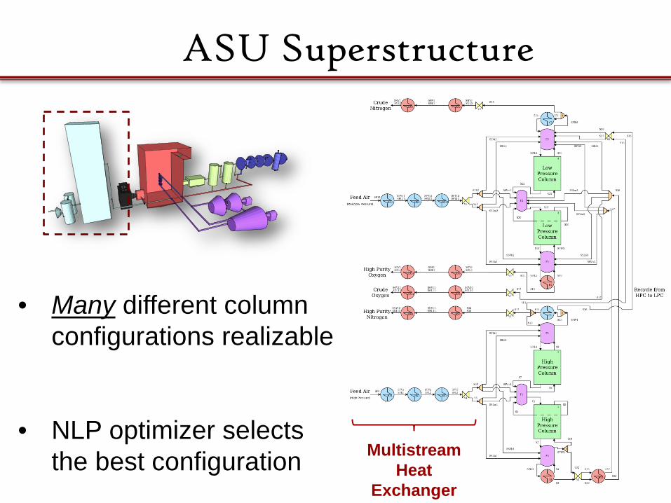
ASU Superstructure
13
• Many different column configurations realizable
• NLP optimizer selects
the best configuration Multistream Heat
Exchanger

Optimization Formulation
Note: Upper and lower bounds not shown above are considered for many variables including stream/equipment temperatures and pressures. 14
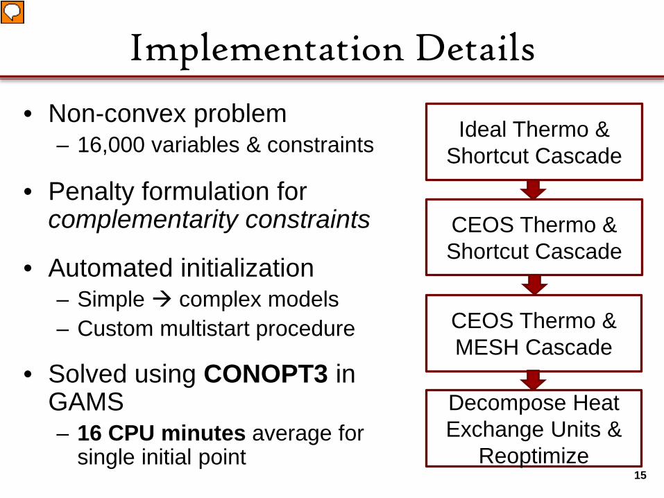
Implementation Details
• Non-convex problem – 16,000 variables & constraints
• Penalty formulation for complementarity constraints
• Automated initialization – Simple complex models – Custom multistart procedure
• Solved using CONOPT3 in GAMS – 16 CPU minutes average for
single initial point 15
Ideal Thermo & Shortcut Cascade
CEOS Thermo & Shortcut Cascade
CEOS Thermo & MESH Cascade
Decompose Heat Exchange Units &
Reoptimize
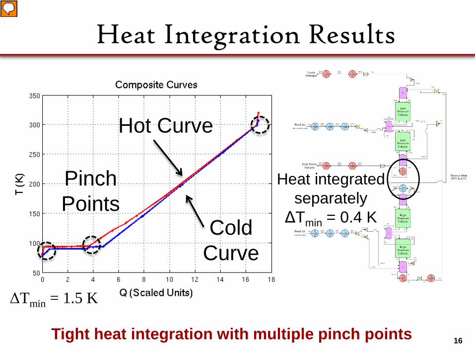
Heat Integration Results
Heat integrated separately
ΔTmin = 0.4 K
Hot Curve
Cold Curve
Pinch Points
ΔTmin = 1.5 K
16 Tight heat integration with multiple pinch points
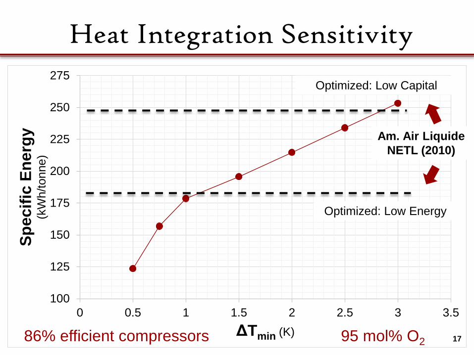
100
125
150
175
200
225
250
275
0 0.5 1 1.5 2 2.5 3 3.5
Spec
ific
Ener
gy
(kW
h/to
nne)
ΔTmin (K)
Heat Integration Sensitivity
17
Optimized: Low Energy
Optimized: Low Capital
Am. Air Liquide NETL (2010)
86% efficient compressors 95 mol% O2

O2 Purity Sensitivity
18
y = 227.62x - 20.288 R² = 0.9966
150
170
190
210
230
250
270
290
88% 89% 90% 91% 92% 93% 94% 95% 96% 97% 98%
Spec
ific
Ener
gy
(kW
h/to
nne)
Oxygen Purity (mole %)
This Study Xiong et al (2011) NETL (2010) - Low CapitalNETL (2010) - Low Energy Amann et al (2009) Linear (This Study)Linear (Amann et al (2009))
This Study: Δ𝑇𝑇𝑚𝑚𝑚𝑚𝑚𝑚 = 1.5 𝐾𝐾

HEN Costs
19
Fixed Stream
Data
Utility Costs
Area Costs
Number of Exchangers
Sequential HENS (LP MILP NLP) No Yes Yes Yes
Simultaneous HENS (MINLP) No Yes Yes Yes
Duran-Grossmann Formulation
(NLP) Yes Yes No No
Goal: Add area costs to the Duran-Grossmann formulation.

Motivation
20
Tem
pera
ture
Heat Qw Qs
ΔTmin
Hot Composite Curve
Cold Composite Curve
Pinch point
Qs
ΔTmin
Hot Composite Curve
Cold Composite Curve
Pinch point
Qw
Same pinch point and utility loads but different driving forces and estimated areas
System A System B

Previous Work: Gomez et al
21
Start
Process Flowsheet
Target for the Heat Exchanger Network and Utility System’s Capital and Operating Costs
Calculate Total Process Costs
Optimal Costs?
Adjust Decision Variables
Figure 5.4 of J. A. Gomez Giammattei (1994, PhD thesis)
Stop
Comments:
• Internally constructs grand composite curves
• Capital costs using Linnhoff and Ahmad’s (1990) method
Properties:
• Implementation requires loops and logical statements
• Non-differentiable optimization problem?

Formulation Specifications
1. Express as algebraic equations – Enables calculation of exact derivatives
2. Temperature intervals and pinch temperature orderings not known a priori
3. Approximate area costs sufficiently for
cost of electricity minimization
22

23
Driving Force Calculation Te
mpe
ratu
re
Heat Qw
𝑇𝑇𝑜𝑜𝑜𝑜𝑜𝑜
𝑇𝑇𝑚𝑚𝑚𝑚
𝑻𝑻𝒊𝒊𝒊𝒊∗ 𝑇𝑇𝑜𝑜𝑜𝑜𝑜𝑜∗
Consider a cold stream Know 𝑇𝑇𝑚𝑚𝑚𝑚 & 𝑇𝑇𝑜𝑜𝑜𝑜𝑜𝑜… calculate 𝑻𝑻𝒊𝒊𝒊𝒊∗ & 𝑇𝑇𝑜𝑜𝑜𝑜𝑜𝑜∗
Qs
Energy Balance: 𝑄𝑄𝑠𝑠 + 𝑄𝑄𝐴𝐴𝐴 𝑻𝑻𝒊𝒊𝒊𝒊∗ = 𝑄𝑄𝐴𝐴𝐴𝐴(𝑇𝑇𝑜𝑜𝑜𝑜𝑜𝑜)
Calculated in Duran-Grossmann formulation
𝑄𝑄𝐴𝐴𝐴 𝑇𝑇𝑚𝑚𝑚𝑚∗ ≔ Heat exchanged above 𝑇𝑇𝑚𝑚𝑚𝑚∗
𝑄𝑄𝐴𝐴𝐴𝐴 𝑇𝑇𝑜𝑜𝑜𝑜𝑜𝑜 ≔ Cold exchanger above 𝑇𝑇𝑜𝑜𝑜𝑜𝑜𝑜

𝑄𝑄𝐴𝐴𝐴 Calculation
24
T
H 𝑇𝑇∗
T
H
𝑇𝑇∗
T
H
𝑇𝑇∗
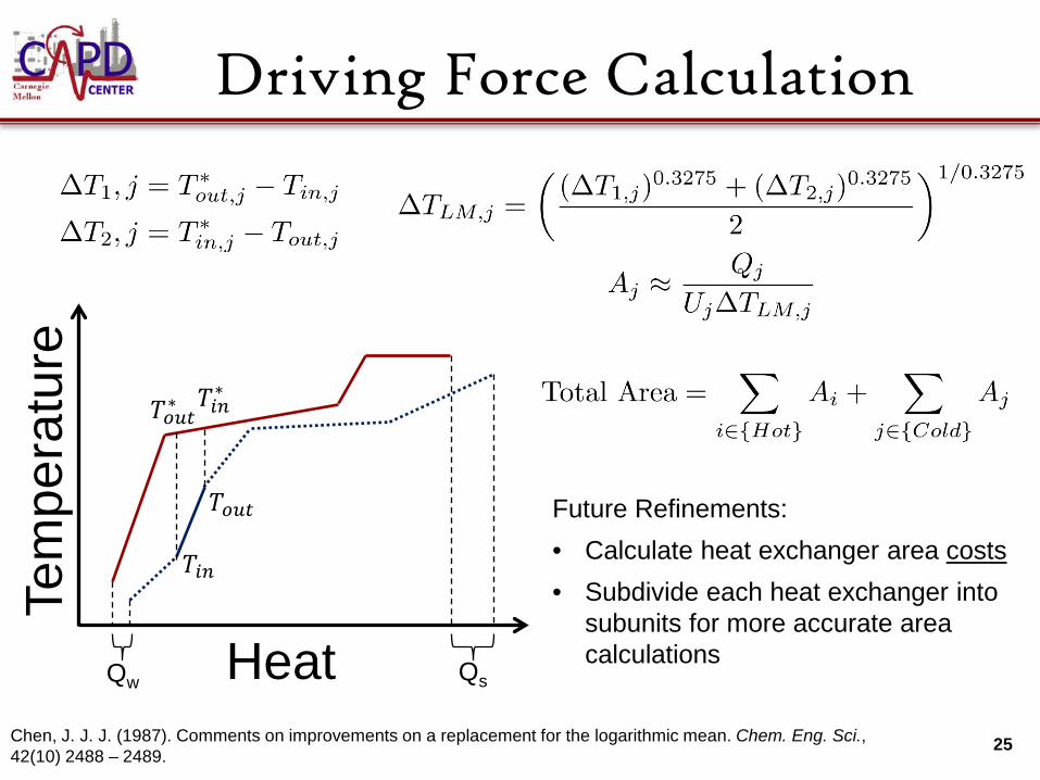
Driving Force Calculation
25
Tem
pera
ture
Heat Qw
𝑇𝑇𝑜𝑜𝑜𝑜𝑜𝑜
𝑇𝑇𝑚𝑚𝑚𝑚
𝑇𝑇𝑚𝑚𝑚𝑚∗ 𝑇𝑇𝑜𝑜𝑜𝑜𝑜𝑜∗
Qs
Chen, J. J. J. (1987). Comments on improvements on a replacement for the logarithmic mean. Chem. Eng. Sci., 42(10) 2488 – 2489.
Future Refinements:
• Calculate heat exchanger area costs
• Subdivide each heat exchanger into subunits for more accurate area calculations

Case Study: CO2 Processing Unit
26
83.5% CO2 330 K
1.03 bar
150 bar CO2 Recovery ≥ 96.3%
CO2 Purity ≥ 94.6%
Based on two-flash system from Fu, C. & Gundersen, T. (2012). Int. J. of Green. Gas Control, 9, 419-727.
30 - 35 bar
Multistream heat
exchanger
Minimize Shaft Work + 0.01 Qcooling water + αA Total Area
using Peng-Robison thermodynamics

Sensitivity to Area Cost
27

Comparison of Extremes
28
Cheap Area 𝛼𝛼𝐴𝐴 = 10−3 kW/m2
Expensive Area 𝛼𝛼𝐴𝐴 = 10−2 kW/m2
23.9 𝑄𝑄𝑤𝑤𝑤𝑤𝑜𝑜𝑤𝑤𝑤𝑤𝐴𝐴𝑜𝑜𝑜𝑜𝑐𝑐𝑚𝑚𝑚𝑚𝑐𝑐 ( 𝑘𝑘𝑘𝑘
𝑚𝑚𝑜𝑜𝑐𝑐𝑤𝑤 𝑓𝑓𝑤𝑤𝑤𝑤𝑓𝑓) 24.1
123.6 Total Area ( 𝑚𝑚2
𝑚𝑚𝑜𝑜𝑐𝑐𝑤𝑤 𝑓𝑓𝑤𝑤𝑤𝑤𝑓𝑓) 58.0
14.73 Specific Energy ( 𝑘𝑘𝑘𝑘𝐴𝑘𝑘𝑐𝑐 𝐶𝐶𝑂𝑂2
) 14.95
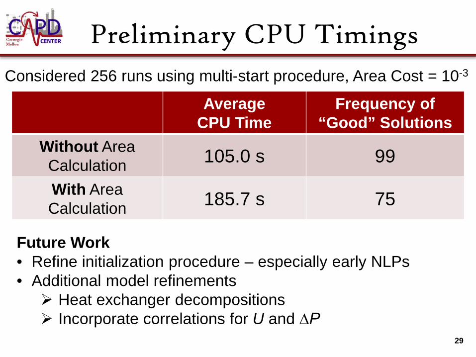
Preliminary CPU Timings
29
Average CPU Time
Frequency of “Good” Solutions
Without Area Calculation 105.0 s 99
With Area Calculation 185.7 s 75
Considered 256 runs using multi-start procedure, Area Cost = 10-3
Future Work • Refine initialization procedure – especially early NLPs • Additional model refinements Heat exchanger decompositions Incorporate correlations for U and ∆P

Integration Opportunities
30
ASU & CPU
• Use refrigeration from the ASU to liquefy CO2
• Less energy required to pump CO2
• Feasibility depends on capital costs
Waste Heat from Compression
• Integrate waste heat from compressors into steam cycle
• Solution strongly sensitive to capital costs

Conclusions • Embedded area estimates in simultaneous
heat integration and flowsheet optimization problems – Variable stream data = add’n degrees of freedom – Does not require order of pinch candidates a priori
• Considered two cases studies with multistream heat exchangers – Air Separation Unit – CO2 Processing Unit
Funding: This presentation was prepared as an account of work sponsored by an agency of the United States Government. Neither the United States Government nor any agency thereof, nor any of their employees, makes any warranty, express or implied, or assumes any legal liability or responsibility for the accuracy, completeness, or usefulness of any information, apparatus, product, or process disclosed, or represents that its use would not infringe privately owned rights. Reference herein to any specific commercial product, process, or service by trade name, trademark, manufacturer, or otherwise does not necessarily constitute or imply its endorsement, recommendation, or favoring by the United States Government or any agency thereof. The views and opinions of authors expressed herein do not necessarily state or reflect those of the United States Government or any agency thereof.
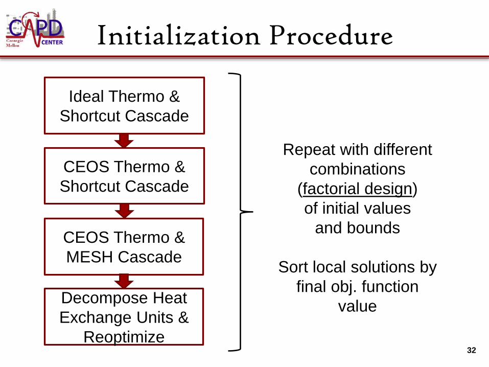
Initialization Procedure
32
Ideal Thermo & Shortcut Cascade
CEOS Thermo & Shortcut Cascade
CEOS Thermo & MESH Cascade
Decompose Heat Exchange Units &
Reoptimize
Repeat with different combinations
(factorial design) of initial values
and bounds
Sort local solutions by final obj. function
value
Sensitivity to Area Cost
33
Area Cost
Specific Energy
Figure is under construction

Future Work: ASU Integration
34 Cooling from Waste N2 (ASU)
CPU Specific Energy
Figure is under construction
89 K 1.1 bar 93% N2
250 K