design of continuous flight auger pile foundation for - theseus
TRANSCRIPT
Saimaa University of Applied Sciences Faculty of Technology, Lappeenranta Double Degree Programme in Civil and Construction Engineering Yulia Yatskevich
DESIGN OF CONTINUOUS FLIGHT AUGER PILE FOUNDATION FOR A MULTI-STOREY APARTMENT BUILDING Bachelor’s Thesis 2010

2
ABSTRACT Yulia Yatskevich Design of Continuous Flight Auger Pile Foundation for a Multi-Storey Apartment Building, 43 pages, 10 appendices Saimaa University of Applied Sciences, Lappeenranta Double Degree Programme in Civil and Construction Engineering Bachelor’s Thesis 2010 Tutors: Mr. Matti Hakulinen, Saimaa University of Applied Sciences O.V. Chernyavskiy, YIT Lentek JSK The object of this work was studying, systemizing and describing continuous flight auger (CFA) pile foundation design for a residential complex and calculating the bearing capacity of a single СFA pile on the basis of Russian Building Code. This thesis was written on the request of the YIT Lentek JSK Design Department.
The information for the theoretical part was gathered from Russian Building Codes, theoretical manuals, other common available materials (including the Internet), and project materials and documents kept in the archive of YIT Lentek JSC. The practical part of the study presents the calculation of bearing capacity of a single СFA pile based on Russian Building Code, called SNiP 2.02.03-85 “Pile Foundations”.
General systematization of the process of CFA pile foundation design for multi-storey apartment buildings, which is useful for further studies, was implemented on the basis of gathered and analyzed materials. Results of a single СFA pile bearing capacity calculation serves for the company as a starting point in determination of bearing capacity of a single CFA pile of a given diameter and length for further considerations and comparisons with other variants of piling. Keywords: Continuous Flight Auger (CFA) Pile, Design, Foundation, Multi-Storey Apartment Building

3
CONTENTS ABSTRACT ......................................................................................................... 2 1 INTRODUCTION ............................................................................................. 4 2 CONTINUOUS FLIGHT AUGER PILES .......................................................... 5
2.1 СFA piles features ..................................................................................... 8 2.2 Construction sequence ............................................................................ 10 2.2.1 Drilling .................................................................................................. 10 2.2.2 Grouting ................................................................................................ 12
3 MULTI-STOREY APARTMENT BUILDING “VITA NOVA” ............................. 14
3.1 General information about the building .................................................... 15 3.2 Location of the building and brief site description .................................... 16
3.3 Architecture ............................................................................................. 16
3.4 Structures ................................................................................................ 18 4 THEORETICAL BASICS OF CFA PILES FOUNDATION DESIGN AND CALCULATION ................................................................................................. 19
4.1 Limit states for design.............................................................................. 19 4.2 Design procedures .................................................................................. 23
5 GEOLOGICAL CONDITIONS OF THE SITE ................................................. 30
5.1 Geological investigations programme ..................................................... 31 5.2 Geological structure of the site ................................................................ 33
5.3 Static sounding of the ground .................................................................. 34 5.4 Groundwater situation ............................................................................. 35
6 CALCULATION OF THE BEARING CAPACITY OF A SINGLE СFA PILE ... 36 7 SUMMARY..................................................................................................... 40
LIST OF FIGURES ........................................................................................... 42 REFERENCES ................................................................................................. 43 APPENDICES
Appendix 1. Master Plan Appendix 2. Perspective Views of Residential Complex ”Vita Nova” Appendix 3. Results of Computing of Forces in Piles Appendix 4. Results of Computing of Pile Cap Appendix 5. Boreholes for Geological Investigations and Static Sounding
Points Location Diagram Appendix 6. Geological Structure of the Site Appendix 7. Geological Cross Sections Appendix 8. Physical and Mechanical Properties of the Soils. Design Values Appendix 9. Seating of a Single СFA Pile on Idealized Geological Profile Appendix 10. Calculation of Shaft Friction Component of a single СFA Pile
Bearing Capacity
4
1 INTRODUCTION
This Bachelor’s Thesis presents research work combined with practical
calculations intended to fulfill the requirements of the Double Degree
Programme in Civil and Construction Engineering at Saimaa University of
Applied Sciences. The focus of the research is on studying, systemizing and
describing the continuous flight auger (CFA) pile foundation design for a
residential complex, and the calculations consist of determination of the bearing
capacity of a single СFA pile on the basis of Russian Building Norms and Rules.
Pile foundations have always occupied a worthy place in engineering practice.
They have come into particularly widespread use in the last 30-35 years. This is
associated with an increase in the number of storeys, an expansion of the
clearance dimensions of buildings and structures, and an increase in the loads
taken up per unit area. They have been used for the development of sites with
unfavorable geologic-engineering conditions, complex relief, high ground-water
table, etc., and in many regions, up to 40-70% of buildings and structures are
raised on pile foundations. Pile foundations are most widely used in America,
Holland, Italy, Russia, France, and Japan. The fact that during the last 30 years
almost every fourth candidate and every third doctoral dissertation, concerning
the "bed and foundation” specialty has been devoted to problems of pile
foundation engineering suggests a high level of experimental-theoretical
research in the field of pile foundation engineering in Russia. (Bartolomei,
1995).
The design of a pile foundation involves solving the complex problem of
transferring loads from the structure through the piles to the underlying soil.
Nowadays pile foundations are extensively used in Saint-Petersburg to support
multi-storey apartment buildings for effective structural loads transfer from the
superstructure to the ground and for avoiding the excessive settlement or lateral
movement.
5
The study of the process of pile foundation design for this type of structure was
carried out through exploration and analyses of data from the YIT Lentek JSC
building pile foundation design. The considered structure is called “Vita Nova”
and information about this building is also presented in the given work. Project
materials and documentation, kept in the YIT Lentek JSC archive, as well as
theoretical manuals and other research works were used for summarizing the
theoretical information.
The calculation of the bearing capacity of a single СFA pile is implemented on
the basis of SNIP 2.02.03-85 “Pile Foundations”, which is Russian Building
Code. This calculation is done to get the opportunity for approximate evaluation
of a single СFA pile bearing capacity for further consideration and comparison
with other variants of piling.
The collection of papers appended to this thesis forms an integral part of the
research and should be read in conjunction with the main text.
2 CONTINUOUS FLIGHT AUGER PILES
This chapter provides general information about continuous flight auger (CFA)
piles which are under consideration in the course of this thesis. It is important
for me to understand the nature of this pile type in general and the process of
their implementation in particular, not only because it affects the calculation of
pile bearing capacity (this will be mentioned in Chapter 6). A thorough
understanding of construction technology of any projected structure is obligatory
for the designers, and as my purpose is to get closer to their work by studying
and highlighting the СFA pile foundation design, this understanding is also
necessary for me.
Piles have been used to provide foundations for over 4000 years and were
widely used by the Ancient Greeks and Romans. Modern piling techniques are
diverse and the term “pile” is used to describe a wide variety of columnar
6
elements in a foundation which transfers load from the superstructure through
weak or compressible strata to more competent soils or rock.
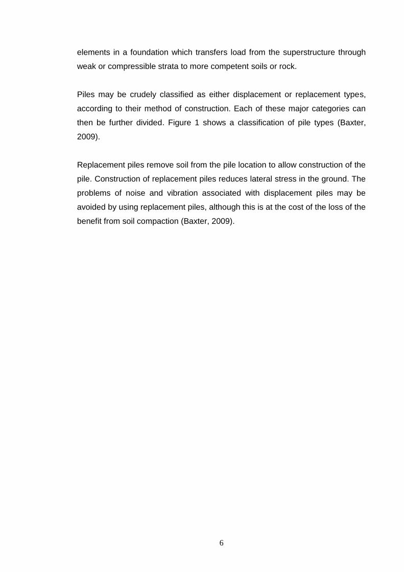
Piles may be crudely classified as either displacement or replacement types,
according to their method of construction. Each of these major categories can
then be further divided. Figure 1 shows a classification of pile types (Baxter,
2009).
Replacement piles remove soil from the pile location to allow construction of the
pile. Construction of replacement piles reduces lateral stress in the ground. The
problems of noise and vibration associated with displacement piles may be
avoided by using replacement piles, although this is at the cost of the loss of the
benefit from soil compaction (Baxter, 2009).

7
Types of bearing
Displacement Replacement
Totally preformed
Driven cast-in-
Grout intruded
Void formed by boring or
excavation
Concrete intruded
CFA Percussion
bored
Rotary bored
Drilled Concrete Steel
Closed-ended Open
Hollow Solid
Steel
Concrete
Concrete Steel Timber
Precast reinforced
Precast prestressed
In these piles concrete is cast directly against the soil (unless deliberately separated by a
membrane)
Fig
ure
1. C
lassific
atio
n o
f pile
type
s
8
As it is shown in Figure 1, CFA piles are subsets of bored replacement piles
formed by drilling an auger with continuous helical flights into the ground to the
required depth and pumping concrete through the hollow auger stem as it is
subsequently withdrawn (Baxter, 2009). Since their worldwide introduction, they
have become increasingly popular, as they can be considerably cheaper than
alternative pile types. With proper planning and design, efficient equipment and
experienced personnel, high production rates can be achieved.
2.1 СFA piles features
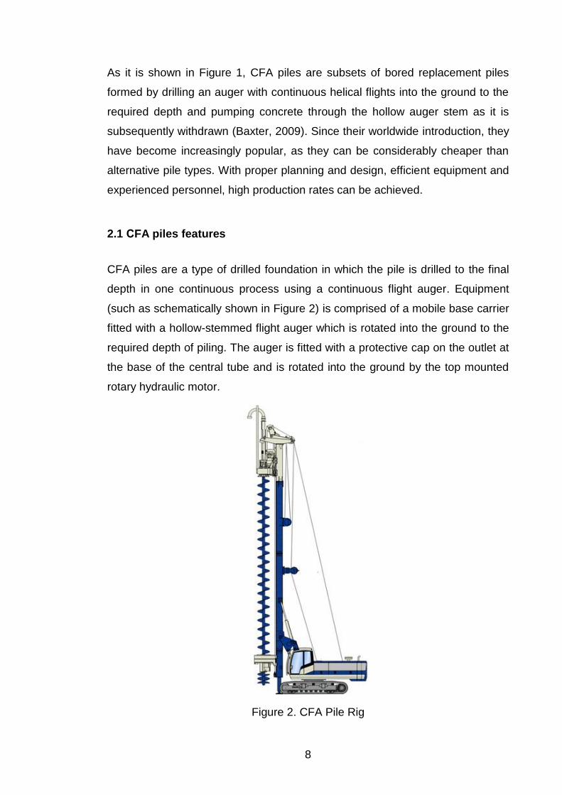
CFA piles are a type of drilled foundation in which the pile is drilled to the final
depth in one continuous process using a continuous flight auger. Equipment
(such as schematically shown in Figure 2) is comprised of a mobile base carrier
fitted with a hollow-stemmed flight auger which is rotated into the ground to the
required depth of piling. The auger is fitted with a protective cap on the outlet at
the base of the central tube and is rotated into the ground by the top mounted
rotary hydraulic motor.
Figure 2. CFA Pile Rig

9
CFA piles are typically installed with diameters ranging from 0.3 to 0.9 m and
lengths of even more than 30 m. European practice tends towards larger
diameters (up to 1.5 m) (GeoSyntec Consultants, 2007).
The method is especially effective on soft ground and enables the installation of
a variety of bored piles of various diameters that are able to penetrate a
multitude of soil conditions. CFA piles are not normally viable in lower strength
clays, unless a suitable end-bearing layer is available. Still, for successful
operation of rotary auger the soil must be reasonably free of tree roots, cobbles,
and boulders, and it must be self supporting.
CFA piles differ from conventional drilled shafts or bored piles, and exhibit both
advantages and disadvantages over conventional drilled shafts. The main
difference is that the use of casing or slurry to temporarily support the hole is
avoided as the sides of the hole are supported at all times by the soil-filled
auger. Drilling the hole in one continuous process is faster than drilling a shaft
excavation, an operation that requires multiple lowering of the drilling bit to
complete the excavation (GeoSyntec Consultants, 2007).
Because CFA piles are drilled and cast in place rather than being driven, as
driven piles are, noise and vibration due to pile driving are minimized. Using
CFA piles also eliminates amounts of splices and cutoffs. Soil heave due to
driving can be eliminated when non-displacement CFA piles are used. A
disadvantage of CFA piles when comparing to driven piles is that the available
methods of the structural integrity and pile bearing capacity verification for CFA
piles are less reliable than those for driven piles. Another disadvantage of CFA
piles is that CFA piles generate soil spoils that require collection and disposal.
Handling of spoils can be a significant issue when the soils are contaminated or
if limited room is available on the site (GeoSyntec Consultants, 2007).
10
2.2 Construction sequence
Of course, this complex study of CFA piles foundation includes observations of
construction methods. At the same time, this information is also useful for me in
practical calculations as the result of drilled piles geotechnical bearing capacity
calculations depends on the manner of their construction (this will be mentioned
later in the 6th Chapter). So, present section provides an overview of the
construction process of CFA piles.
2.2.1 Drilling
The key component of the CFA pile system contributing to the speed and
economy of these piles is that the pile is drilled in one continuous operation
using a continuous flight auger, thus reducing the time required to drill the hole.
While advancing the auger to the required depth, it is essential that the auger
flights be filled with soil so that the stability of the hole is maintained.
A variety of auger types may be used to drill the piles depending on the soil
conditions encountered. Selecting the correct auger pitch is important, because
for a given soil type an excessively large pitch could result in mining of the soil
around the pile (GeoSyntec Consultants, 2007).
As the auger cuts the soil at the base of the tool, material is loaded onto the
flights of the auger. The volume of soil through which the auger has penetrated
will tend to take up a larger volume after cutting than the in-situ volume. Some
of the extra volume appears also due to the volume of the auger itself, including
the hollow center tube. Thus, it is necessary that some soil is conveyed up the
auger during drilling. To maintain a stable hole at all times, it is necessary to
move only enough soil to offset the auger volume and material bulking without
exceeding this volume.
If the auger turns too rapidly, with respect to the rate of penetration into the
ground, then the continuous auger acts as a sort of “Archimedes pump” and
conveys soil to the surface. This action can result in a reduction of the

11
horizontal stress necessary to maintain stability of the hole. Consequently,
lateral movement of soil towards the hole and material loss due to
overexcavation can result in ground subsidence at the surface, and reduced
confinement of nearby installed piles.The bottom of Figure 3 illustrates an auger
having too high rotation speed comparing with penetration rate; as a result, the
auger feeds from the side with attendant decompression of the ground. The top
of Figure 3 represents an auger having balanced auger rotation and penetration
rates, so that the flights are filled from the digging edge at the base of the auger
with no lateral “feed”.
Figure 3. Effect of overexcavation using CFA piles
Controlling the rate of penetration helps to avoid lateral decompression of the
ground inside the hole, loosening of the in-situ soil around the hole, and ground
subsidence adjacent to the pile. The proper rate of penetration may be difficult
to maintain if the rig does not have adequate torque and down-force to rotate
the auger.
12
2.2.2 Grouting
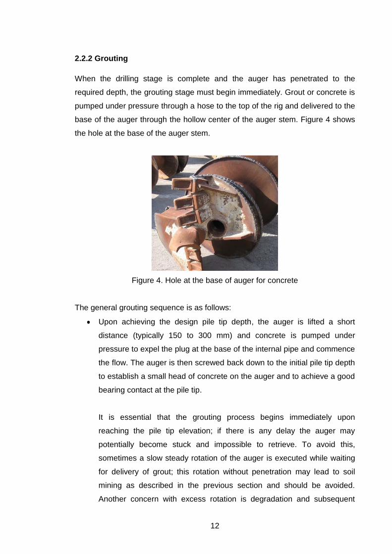
When the drilling stage is complete and the auger has penetrated to the
required depth, the grouting stage must begin immediately. Grout or concrete is
pumped under pressure through a hose to the top of the rig and delivered to the
base of the auger through the hollow center of the auger stem. Figure 4 shows
the hole at the base of the auger stem.
Figure 4. Hole at the base of auger for concrete
The general grouting sequence is as follows:
Upon achieving the design pile tip depth, the auger is lifted a short
distance (typically 150 to 300 mm) and concrete is pumped under
pressure to expel the plug at the base of the internal pipe and commence
the flow. The auger is then screwed back down to the initial pile tip depth
to establish a small head of concrete on the auger and to achieve a good
bearing contact at the pile tip.
It is essential that the grouting process begins immediately upon
reaching the pile tip elevation; if there is any delay the auger may
potentially become stuck and impossible to retrieve. To avoid this,
sometimes a slow steady rotation of the auger is executed while waiting
for delivery of grout; this rotation without penetration may lead to soil
mining as described in the previous section and should be avoided.
Another concern with excess rotation is degradation and subsequent

13
reduction or loss of side friction capacity. So, the practice of maintaining
rotation without penetration is not recommended. The best way to avoid
such problems is to not start the drilling of a pile until an adequate
amount of concrete is available at the jobsite to complete the pile.
The concrete is pumped continuously under pressure (typically up to
2MPa measured at the top of the auger) while the auger is lifted
smoothly in one continuous operation. This pressure replaces the soil-
filled auger as the lateral support mechanism in the hole. When the grout
pressure is applied, the grout also pushes up the auger flights and
presses the soil against the auger.
As the auger is slowly and steadily withdrawn, an adequate and
controlled volume of concrete must be delivered at the same time to
replace the volume of soil and auger being removed. If the auger is
pulled too fast in relation to the ability of the pump to deliver volume, the
soil will tend to collapse inward and form a neck in the pile.
During grouting, the auger should be pulled with either no rotation or
slow continuous rotation in the direction of drilling. A static pull with no
rotation can help maintain a static condition at the base of the auger
against which the grout pressure acts. Some contractors prefer to rotate
the auger slowly during withdrawal to minimize the risk of having the
auger flight getting stuck. Simultaneously, as the auger is lifted, the soil is
removed from the flights at the ground surface so that soil cuttings are
not lifted high into the air.
After the concreting procedure is completed, any remaining soil cuttings
are removed from the area at the top of the pile and the top of the pile is
cleared of debris and contamination with a dipping tool.
The reinforcement cage is lowered into the fluid concrete to the required
depth immediately after the auger is removed. In general, reinforcement
lengths between 10 and 15 m are considered feasible, depending on soil

14
conditions. However, longer reinforcement has been used. A minimum
cover of 75 mm is commonly adopted for most applications. Difficulties in
placing the cage can arise if the concrete starts to set and loses
workability. Soil conditions can also have an effect on the reinforcement
placement, as a free draining sand or dry soil can tend to dewater the
concrete rapidly and lead to increased difficulty in placing the cage.
A common practice in Europe is to utilize a small vibratory drive head to
install the cage. The use of a vibratory drive head might lead to problems
with cages that are not securely tied or welded, and might also produce
segregation and bleeding if the concrete mix is not well proportioned.
3 MULTI-STOREY APARTMENT BUILDING “VITA NOVA”
The design and construction of any structure requires a thorough understanding
of the properties of the type, load and performance criteria, location, and
geometry of the proposed facility. The pile foundation preliminary analysis,
design and calculation are also based upon the functional and structural
significance of the building. So, the type, purpose, function and structures affect
decisions regarding subsurface investigation programs and the type of
foundation. Thereby, the idea of this chapter is to provide basic information
about the main project decisions regarding the building, the design of which pile
foundation was the focus of this work, and its structures. The main sources
presented in this part of the work were project materials and documentation
worked out by the JUVA Oy, adapted for Russian norms by JUVA RUS Ltd
together with Genproject Ltd, and kept in the archive in the YIT Lentek JSC
office.

15
3.1 General information about the building
The building being designed is a multi-storey residential house with built-in and
attached office and public premises. The whole residential complex is called
“Vita Nova”. It consists of 7 sections of different heights which are shown in
Figure 1.
As shown in Figure 5, the architectural structure of the whole complex has a
symmetrical nature. In the plan the building is “V” shaped with distinctly marked
corner. Sections NoNo 1, 2, 6, 7 (each has 23 floors), divergent along the
streets, together with corner section No 4 (25 floors) compose the complex’s
altitude parts. Section No 3 and section No 5 have 2 floors. Sections NoNo 2, 6, 7
are identical and have a rectangular shape with dimensions in axes
33.2x17.9m.
Figure 5. Residential complex “Vita Nova”. Sections’ location plan

16
3.2 Location of the building and brief site description
The area of design and construction is located in the north-western part of
St.Petersburg. The address is: St.Petersburg, Primorsky district, Mebelnaya
Street, parcel No 1 westerly from the crossroad with Turistskaya Street. The
considered site has not previously been built up: there are neither permanent
nor temporary old structures (buildings or supplying systems) on the building
site. So, there is no need for any dismantling work before the start of
construction.
The relief of the site is steady: absolute marks of ground surface are from
+3.210 m to +6.440 m above the sea level. Such low absolute marks are typical
for St.Petersburg which is located in the northern-western part of the Nevsky
lowland terrain.
The entrance to the territory of the residential complex is accessed from the
sides of Mebelnaya and Kamyshovaya streets. The master plan with all the
necessary designations is presented in Appendix 1. The total area of the
described site is 19 834 m2, with a building area is 4 784 m². Thus, the building
density rate is, as follows, 24%.
3.3 Architecture
Architectural and planning solutions, due to absence of strict environmental
factors and conditions, are conditioned by economical and technological
features of existing buildings and design tasks and requirements (Genprojekt
Ltd, 2007).
3.3.1 Facades and exterior finishing
Pictures of perspective views, worked out by YIT Lentek’s designers, which
show the whole design of the building, are presented in Appendix 2. All the
peculiarities of the building’s appearance can be seen there.

17
Facades have vertical and horizontal divisions, emphasizing the functional
nature of the building, and glazed balconies and loggias. Decorative white and
grey plaster is used for facade finishes. For the 1st floor, exterior finishing in
grey coloured (natural) concrete stone is used.
3.3.2 Functional and planning solutions
The building has a basement floor which is partly occupied with household
pantries for residents. Pump units, individual heating units, cable spaces and
metering units are also situated on the base floor.
Underground parking (total area 5 957 m²) which provides 249 places for cars is
attached to the building. The entrance to the underground parking is accessed
by a double-entry ramp which is separated from entrances to dwellings and
offices in accordance with Russian Sanitary Standards.
The built-in office and public premises (café, club rooms and technical areas)
are located on the 1st floor in all sections and on the 2nd floor in sections NoNo 3,
4 and 5. Their total area is 4 784 m². Each built-in facility has its own private
entrance to ensure compliance with fire safety requirements.
It is important to note, that commercial premises located on the first floors of
residential buildings, are examples of rare cases when the interests of all
parties (business structures – potential tenants, developers and residents)
coincide. It is difficult for developers to sell apartments on the first floors,
because not many people want to live there, but at the same time original
planning and positioning of these areas as commercial is interesting enough for
them. First floor apartments have always had lower demand from buyers and
there are many reasons for this: the first floors are the least protected from
external intrusion, street noise, and other "minor" troubles. As usual, there is
also no balcony in an apartment located on the first floor. People who live
higher like to have small shops, a pharmacy, a hairdressing salon or similar
convenience downstairs.

18
Dwelling spaces are on the 2nd floor and higher and in corner section No 4 on
the 3rd floor and higher. Apartments have from 1 to 4 rooms of different areas.
The total amount of apartments projected inside the building is 853. Their total
area is 53 634.06 m².
3.4 Structures
The foundation slab is monolithic, with a constant cross section’s thickness of
800 mm. The slab rests directly on pile foundation. More details about
foundations will be given later.
Taking into consideration the high groundwater level (section 3.3 of this thesis)
and to increase reliability of constructive solutions, the basement is
implemented monolithically. Cast-in-place external and internal walls and
columns are rigidly jointed with the ceiling slab, thus forming a system of load-
bearing frames and load-bearing walls in both transversal and longitudinal
directions.
The constructive scheme of the superstructure is a composite (precast-cast-in-
place) system with load-bearing walls arranged mainly in the transversal
direction, but also in the longitudinal one. Load-bearing elements of floors and
roofing are cast-in-situ reinforced concrete slabs with a 220 mm thickness.
Vertical load-bearing elements in the basement and on the 1st floor are cast-in-
situ columns with a cross-section of 600x400 mm, and precast walls with a 160
mm thickness with cast-in-situ joints. Cast-in-situ external and internal walls
(160 mm) are load-bearing elements on the 2nd floor; the joints are also cast-in-
situ (rigid). From the 3rd floor and higher, external and internal load-bearing
walls are precast reinforced concrete panels with a 160 mm thickness (JUVA
RUS Ltd., 2007).

19
4 THEORETICAL BASICS OF CFA PILES FOUNDATION DESIGN
AND CALCULATION
As it was mentioned earlier, one purpose of this thesis is to study and describe
the process of pile foundation design of the residential complex and calculating
CFA piles bearing capacity. This chapter provides the results of the theoretical
study: a general overview of the theoretical basis of this pile type design and
calculation.
The purpose of a pile foundation is to transmit the loads of a superstructure to
the underlying soil while preventing excessive structural deformations. Design
of a pile foundation involves solving the complex problem of transferring loads
from the structure through the piles to the underlying soil. The capacity of the
pile foundation is dependent on the material and geometry of each individual
pile, the pile spacing (pile group effect), the strength and type of the surrounding
soil, the method of pile installation, and the direction of applied loading (axial
tension or compression, lateral shear and moment, or combinations). In
general, the ultimate capacity is limited by either the structural strength of the
pile shaft or the capacity of the supporting soil.
4.1 Limit states for design
The design method presented is based on an Allowable Stress Design (ASD)
for geotechnical conditions, in which a factor of safety is applied to ultimate limit
state conditions to obtain allowable resistance values for design. The structural
design of the pile is in accordance with those for other reinforced concrete
structural elements. In general, there are three limit state conditions that must
be satisfied for design of CFA and other deep foundations:
1. Geotechnical Ultimate Limit State (GULS)
The pile should have a load resistance that is greater than the expected loads
(service loads) by an adequate margin to provide the required level of safety
20
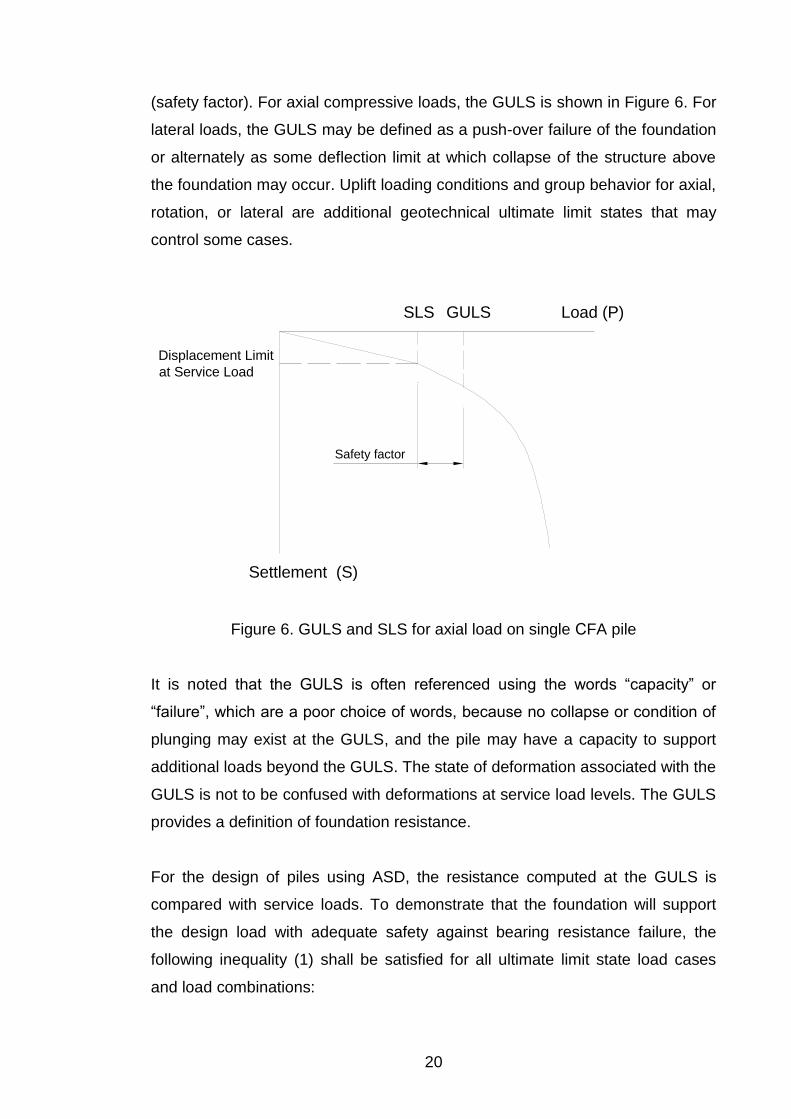
(safety factor). For axial compressive loads, the GULS is shown in Figure 6. For
lateral loads, the GULS may be defined as a push-over failure of the foundation
or alternately as some deflection limit at which collapse of the structure above
the foundation may occur. Uplift loading conditions and group behavior for axial,
rotation, or lateral are additional geotechnical ultimate limit states that may
control some cases.
Load (P)
Settlement (S)
SLS
Displacement Limit
at Service Load
GULS
Safety factor
Figure 6. GULS and SLS for axial load on single СFA pile
It is noted that the GULS is often referenced using the words “capacity” or
“failure”, which are a poor choice of words, because no collapse or condition of
plunging may exist at the GULS, and the pile may have a capacity to support
additional loads beyond the GULS. The state of deformation associated with the
GULS is not to be confused with deformations at service load levels. The GULS
provides a definition of foundation resistance.
For the design of piles using ASD, the resistance computed at the GULS is
compared with service loads. To demonstrate that the foundation will support
the design load with adequate safety against bearing resistance failure, the
following inequality (1) shall be satisfied for all ultimate limit state load cases
and load combinations:
21
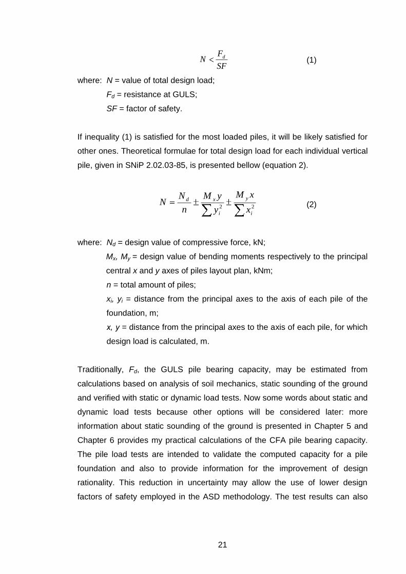
SF
FN d
(1)
where: N = value of total design load;
Fd = resistance at GULS;
SF = factor of safety.
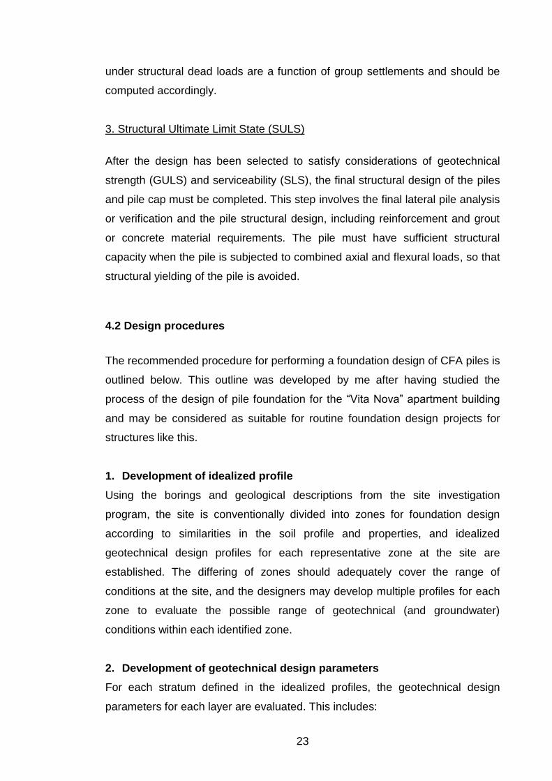
If inequality (1) is satisfied for the most loaded piles, it will be likely satisfied for
other ones. Theoretical formulae for total design load for each individual vertical
pile, given in SNiP 2.02.03-85, is presented bellow (equation 2).
22
i
y
i
xd
x
xM
y
yM
n
NN (2)
where: Nd = design value of compressive force, kN;
Mx, My = design value of bending moments respectively to the principal
central x and y axes of piles layout plan, kNm;
n = total amount of piles;
xi, yi = distance from the principal axes to the axis of each pile of the
foundation, m;
х, у = distance from the principal axes to the axis of each pile, for which
design load is calculated, m.
Traditionally, Fd, the GULS pile bearing capacity, may be estimated from
calculations based on analysis of soil mechanics, static sounding of the ground
and verified with static or dynamic load tests. Now some words about static and
dynamic load tests because other options will be considered later: more
information about static sounding of the ground is presented in Chapter 5 and
Chapter 6 provides my practical calculations of the CFA pile bearing capacity.
The pile load tests are intended to validate the computed capacity for a pile
foundation and also to provide information for the improvement of design
rationality. This reduction in uncertainty may allow the use of lower design
factors of safety employed in the ASD methodology. The test results can also

22
be used to evaluate correlations of side and base resistance with site-specific
soil parameters, and to revise or improve the design.
Static testing involves the application of static loads and the direct
measurement of piles movements. It is the most fundamental form of pile load
test. Loading is applied to the test pile using a calibrated hydraulic jack, and
where required, a calibrated load cell measures the load. Direct measurements
of pile displacement under the applied loading are taken by reading
deflectometers. Test results are presented unconventional graphical format
showing the applied load versus pile head displacement. At some load, the
movement of a pile becomes unacceptable (the unacceptable value for multi-
story apartment building is 20% of limit value of absolute settlement) and this
load is considered as a pile bearing capacity.
Dynamic load testing is a quick method to evaluate the bearing capacity of a
pile for loads similar to the design ones. It can be used for both prefabricated
and cast-in-place piles. It is considerably faster than the static load test.
Dynamic load testing is carried out with two identical bolt-on strain and
acceleration sensors attached to a section of pile with anchor bolts. The pile is
then struck with a driving hammer or a separate drop weight. A hammer mass
of about 1 to 2% of the test load is generally sufficient. The generated
compressive stress wave travels down the piles and reflects from the pile toe
upward. The stress waves, which are picked up by the sensors, are processed
and automatically stored in the computer for further analysis and reporting. Pile
and soil data are modeled and a response is calculated.
2. Service Limit State (SLS)
The pile should undergo deformations at service load levels that are within the
tolerable limits appropriate for the structure. The actual definition of the service
limits should be determined by a rational assessment of the sensitivity of the
structure to deformations. Short-term deformations for transient loadings are a
function of the mobilization of pile resistance. However, long-term settlements
23
under structural dead loads are a function of group settlements and should be
computed accordingly.
3. Structural Ultimate Limit State (SULS)
After the design has been selected to satisfy considerations of geotechnical
strength (GULS) and serviceability (SLS), the final structural design of the piles
and pile cap must be completed. This step involves the final lateral pile analysis
or verification and the pile structural design, including reinforcement and grout
or concrete material requirements. The pile must have sufficient structural
capacity when the pile is subjected to combined axial and flexural loads, so that
structural yielding of the pile is avoided.
4.2 Design procedures
The recommended procedure for performing a foundation design of CFA piles is
outlined below. This outline was developed by me after having studied the
process of the design of pile foundation for the “Vita Nova” apartment building
and may be considered as suitable for routine foundation design projects for
structures like this.
1. Development of idealized profile
Using the borings and geological descriptions from the site investigation
program, the site is conventionally divided into zones for foundation design
according to similarities in the soil profile and properties, and idealized
geotechnical design profiles for each representative zone at the site are
established. The differing of zones should adequately cover the range of
conditions at the site, and the designers may develop multiple profiles for each
zone to evaluate the possible range of geotechnical (and groundwater)
conditions within each identified zone.
2. Development of geotechnical design parameters
For each stratum defined in the idealized profiles, the geotechnical design
parameters for each layer are evaluated. This includes:
24
a. Soil strength parameter values (such as shear strength, friction angle and
cone tip resistance). These strength parameters will be used either directly
or through correlations to estimate unit side-shear and end-base
resistances.
b. Soil stiffness or modulus and other parameters related to deformation
characteristics.
c. Other soil properties that may be needed for design, such as unit weights
and index tests for classification.
3. Obtaining the loadings for the foundation
The design loadings will mostly include several cases of both axial and lateral
loads. Many different load combinations exist of dead loads, temporary loads,
wind and snow loads, etc. Some combinations will include extreme event
loadings. Analyses of the load combinations will reveal the maximum axial and
lateral loads imposed to the pile and represent the critical design cases.
4. Safety factors for design
The safety factors are suggested for general use in design for strength, and
differ depending on the level of site specific testing and quality control. Large
values may be applied in cases where unusual variability in subsurface
conditions exist, difficult construction conditions are expected, or if other
considerations for the structure require this. For example, where base
resistance contributes a large portion of the axial resistance and the properties
of the bearing stratum are quite variable, it may be appropriate to use a
significantly greater safety factor on base resistance than side-shear even
where a load test is performed.
5. Trial design of individual CFA pile
The number of piles used to support the foundation loadings will be determined
by individual pile bearing capacity. At this point in the process, experience and
preliminary calculations should suggest some reasonable values of nominal
axial and lateral resistance for a single pile so that an efficient layout can be
developed later. A range of diameters and lengths may be considered for
25
groups of piles, as it is feasible to consider foundations with larger numbers of
smaller capacity piles vs. fewer numbers of larger capacity piles.
A. Design for Lateral Loading
Lateral analyses may only be needed if lateral loads are significant. As a guide,
lateral shear forces on vertical piles that are less than about 9 to 22 kN per pile
for piles with diameter up to 915 mm would probably not justify lateral analysis
at this point in the design process, and the designer could skip the lateral
analyses and move on to design for axial load (GeoSyntec Consultants, 2007).
Select a diameter that is sufficient to provide the necessary nominal lateral load
resistance and service load requirements for deflection. In general, smaller
diameter and greater length piles tend to be more economical than larger
diameter, shorter length piles with similar axial resistance. So, pile diameter is
often controlled by lateral shear and bending moment considerations. Lateral
load considerations almost never control the length of CFA.
When lateral loads are significant, the final design of CFA piles for lateral
loading is typically controlled by structural design considerations and the
necessary flexural strength and reinforcement. Very high bending stresses
combined with unsupported length may preclude the use of CFA piles at all.
The lateral load analysis of a trial pile design should proceed as follows:
1. Select a trial pile diameter and length. Select a trial longitudinal
reinforcement. A longitudinal reinforcement with a cross-sectional area of
around 1% of the pile cross sectional area is typically a good initial value to
consider. Construct a computer model for the load conditions likely to be most
critical for lateral load considerations.
2. With the pile modeled as a linear elastic beam, foundation strength conditions
are evaluated by computing the foundation response of the pile due to service
loads multiplied by a safety factor to ensure that the pile embedment into the
soil has adequate reserve capacity. Service load deflections or structural

26
strength requirements generally control lateral load design, but this “push-over”
type analysis is performed to ensure that adequate reserve strength exists with
respect to the soil resistance. It also should be noted that there may be several
different load combinations to be evaluated, although there is usually a clearly
dominant lateral loading case.
3. Verification that the amount and depth of longitudinal reinforcement is
adequate for the maximum bending stress computed with the computer
program as in step 2.
4. With the pile modeled as a nonlinear reinforced concrete beam, foundation
deflections due to service loads are evaluated. If the deflections are larger than
the service load requirements, the pile diameter may need to be increased. If
the lateral loads are very high, the use of structural steel pipe or H sections for
reinforcement in CFA piles, or selection of alternative deep foundation systems
should be considered.
B. Design for Axial Loading
After the diameter is selected, determine the length of pile required to provide
the necessary axial resistance. The allowable axial resistance (ultimate axial
resistance divided by the factor of safety) is compared to the service loads to
ensure that the design meets strength requirements.
The most efficient approach for design is to check the first ultimate limit state
conditions and then serviceability. These limit states for design were fully
described in the previous section.
6. Pile layout
The simplest pile layout is one without batter piles. Such a layout should be
used if the magnitude of lateral forces is small. In this case, the designer begins
by dividing the largest vertical load on the structure by the reduced computed
pile capacity (this provides a good starting point to determine an initial layout) to
obtain the approximate number of piles.

27
A uniform pile grid should be developed based on the estimated number of
piles, the required pile spacing and the area of the pile cap. An ideal layout for
flexible structures will match the pile distribution to the distribution of applied
loads. This match will result in equal loads on all piles and will minimize the
internal forces in the structure because the applied loads will be resisted by
piles at the point of loading.
After the preliminary layout has been developed, the remaining load cases
should be investigated and the pile layout revised to provide an efficient layout.
The goal should be to produce a pile layout in which most piles are loaded as
near to capacity as practical for the critical loading cases with tips located at the
same elevation for the various pile groups within a given monolith. Adjustments
to the initial layout by the addition, deletion, or relocation of piles within the
layout grid system may be required. Large concentrations of piles under the
centre of the pile cap should be avoided. This could lead to load concentration
resulting in local settlement and failure in the pile cap (Dalmatov, 2002).
7. Pile group capacity
The geometry and layout of the pile group will affect individual loads per pile.
For pile groups with complex 3-D modeling load conditions or soil layering, the
pile group capacity will require analyses using computer-based pile group
analysis methods. Computer-based tools can be effectively used to optimize
foundation layout and load distribution to the piles. To illustrate the computing of
pile group capacity, in Appendix 3 I have placed pictures showing the results of
computing of internal forces which occur in drilled piles under the action of one
of the load combinations obtained by the engineers with the help of SCAD
Office 11.1.
8. Pile group settlements
Settlements of pile groups should be calculated to give the designer a
perception of how the structure will perform and to check that these calculated
settlements are within acceptable limits. These limits are set in accordance with
SNiP 2.02.01-83* “Foundations of Buildings and Structures” and for multistorey
28
buildings with reinforced bearing walls the limit value of absolute settlement is
10 cm.
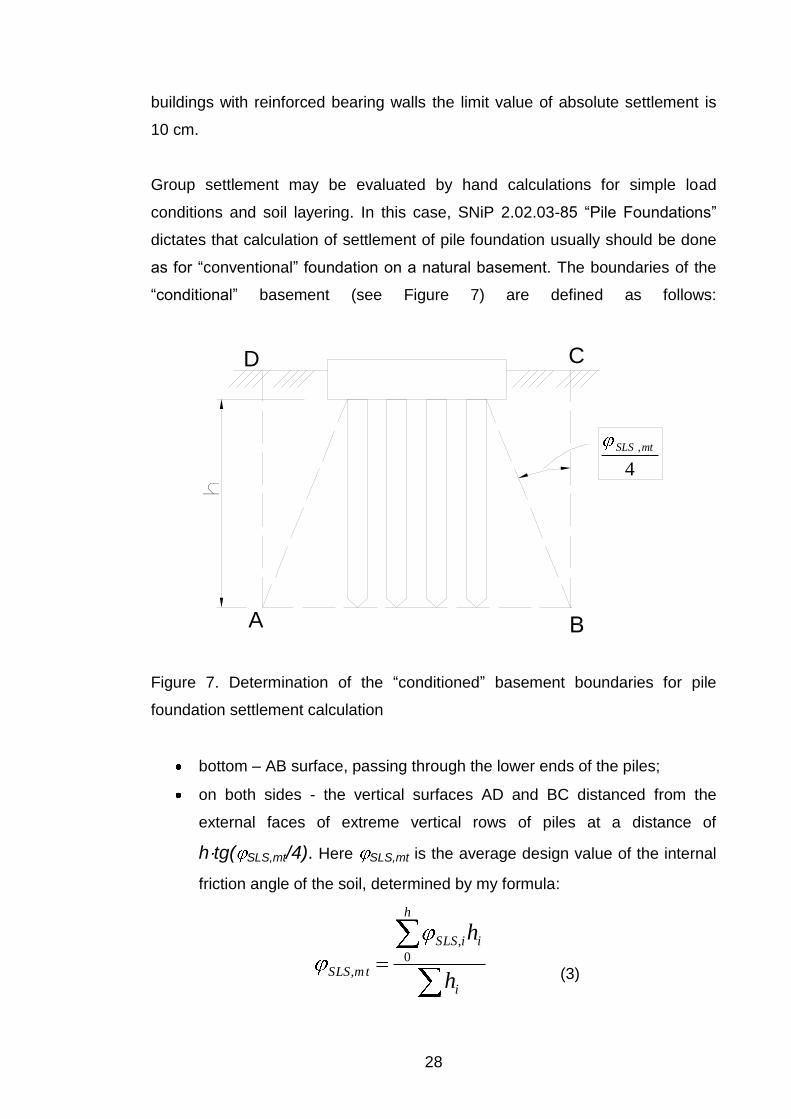
Group settlement may be evaluated by hand calculations for simple load
conditions and soil layering. In this case, SNiP 2.02.03-85 “Pile Foundations”
dictates that calculation of settlement of pile foundation usually should be done
as for “conventional” foundation on a natural basement. The boundaries of the
“conditional” basement (see Figure 7) are defined as follows:
h
A
CD
22° 4
,mtSLS
Figure 7. Determination of the “conditioned” basement boundaries for pile
foundation settlement calculation
bottom – AB surface, passing through the lower ends of the piles;
on both sides - the vertical surfaces AD and BC distanced from the
external faces of extreme vertical rows of piles at a distance of
h tg( SLS,mt/4). Here SLS,mt is the average design value of the internal
friction angle of the soil, determined by my formula:
i
h
iiSLS
mtSLSh
h0
,
, (3)
29
top - the ground surface CD
For pile groups with complex 3-D load conditions or soil layering, the pile group
capacity may also require computer-based pile group analysis methods.
However, most settlement analysis methods are based on empirical methods
and give a rough approximation of the actual settlement.
9. Pile group lateral behavior
This may be sufficient for most pile groups, and a sensitivity analysis may be
considered to determine primarily the effect of the pile-head fixation. However,
for pile groups with complex soil-pile interaction or cap designs, the pile group
lateral capacity may also require computer-based pile group analysis methods.
10. Structural design of piles and pile cap
Normally, pile foundation of multistorey apartment building consists of pile cap
and a group of piles. The pile cap distributes the applied load to the individual
piles which, in turn, transfers the load to the bearing ground. The individual piles
are spaced and connected to the pile cap or tie beams and trimmed in order to
connect the pile to the structure at cut-off level.
After the design has been selected to satisfy considerations of geotechnical
strength (GULS) and serviceability (SLS), the final structural design of the piles
and pile cap must be completed. This step will involve the final lateral pile
analysis or verification and the pile structural design, including reinforcement
and grout or concrete material requirements.
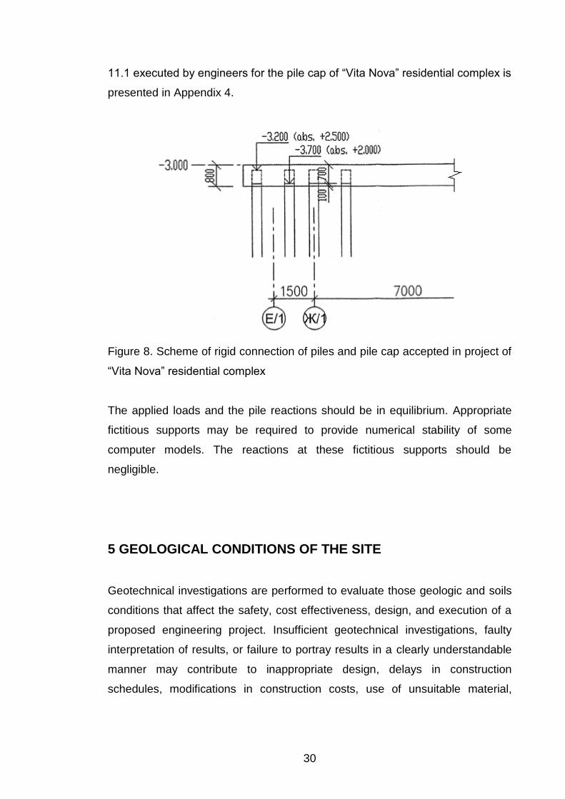
If the pile group is analyzed with a flexible base, then the forces required to
design the base are obtained directly from the structure model. If the pile group
is analyzed with a rigid base, as it was done in initial design of the “Vita Nova”
residential complex driven piles foundation (Figure 8 shows the rigid connection
of piles and pile cap provided by 700 mm of exposed reinforcing rebars
anchored in the pile cap), then a separate analysis is needed to determine the
stresses in the pile cap. The example of this kind of computing in SCAD Office
30
11.1 executed by engineers for the pile cap of “Vita Nova” residential complex is
presented in Appendix 4.
Figure 8. Scheme of rigid connection of piles and pile cap accepted in project of
“Vita Nova” residential complex
The applied loads and the pile reactions should be in equilibrium. Appropriate
fictitious supports may be required to provide numerical stability of some
computer models. The reactions at these fictitious supports should be
negligible.
5 GEOLOGICAL CONDITIONS OF THE SITE
Geotechnical investigations are performed to evaluate those geologic and soils
conditions that affect the safety, cost effectiveness, design, and execution of a
proposed engineering project. Insufficient geotechnical investigations, faulty
interpretation of results, or failure to portray results in a clearly understandable
manner may contribute to inappropriate design, delays in construction
schedules, modifications in construction costs, use of unsuitable material,

31
environmental damage to the site, postconstruction remedial work, and even
failure of a structure.
5.1 Geological investigations programme
Whereas the properties of man-made materials (e.g., brick, concrete, steel) can
be varied on demand, soil and rock formations have already been provided by
Mother Nature, and in many cases, have been in place for many thousands of
years. Thus, the properties of soil and rock must be evaluated through a
program of limited testing and sampling.
A detailed investigation was performed by LenTISIZ JSC for the purpose of
detailed site characterization to be used for design. As is frequently done, the
design phase investigation was performed in two stages: in March and August
2007.
The initial stage investigation is typically performed early in the design process
prior to defining the proposed structure elements or the specific locations of
foundations. Accordingly, this stage of investigation typically includes a limited
number of borings and testing sufficient for defining the general stratigraphy,
soil characteristics, groundwater conditions, and other existing features which
are important for foundation design. The following types of work were executed
in the 1st stage of the survey (in March 2007):
Drilling of 8 boreholes (brh. 1–8) of depths from 35.00 m to 40.00 m,
the total drilling meterage – 305.00 m;
Static sounding of the ground in 7 points (ssp. 1–7) to a depth from
26.00 m to 31.20 m, the total sounding meterage – 181.7 m;
Sampling for laboratory tests: 57 disturbed samples and 72
undisturbed samples for ground properties testing and 3 groundwater
samples for water chemical composition testing (LenTISIZ JSC
2007).

32
Subsequently, after the location of structure foundations and other design
elements had been determined, the second investigation phase was performed
to obtain site specific subsurface information at the final substructure locations
for design purposes and to reduce the risk of unanticipated ground conditions
during construction. The following types of work were executed during the 2nd
stage of the survey (in August 2007):
Drilling of 13 boreholes (brh. 9–21) of depths from 40.00 m to 48.00
m, the total drilling meterage – 558.00 m;
Static sounding of the ground in 13 points (ssp. 9–21) to a depth from
28.00 m to 31.40 m, the total sounding meterage – 392.8 m;
Sampling for laboratory tests: 84 disturbed samples and 164
undisturbed samples for ground properties testing and 2 groundwater
samples for water chemical composition testing (LenTISIZ JSC
2007).
The total number and depths of borings provide adequate coverage and are
sufficient to reasonably define the subsurfaces in the site area. Archive
materials of borings of recent years’ geological surveys of this site and adjacent
territories were also studied and analysed during the investigations (brh. NoNo
213, 280, 282, 283 and 285) as the review of existing data is actually the first
step in the investigation process. A plan of the locations of all drilled boreholes
and static sounding points is presented in Appendix 5.
The purpose of laboratory tests is to investigate the physical and hydrological
properties of soil, determine index values for identification and correlation by
means of classification tests, and define the engineering properties in
parameters usable for the design of foundations. Soil samples obtained for
laboratory tests and analysis were of two main categories: disturbed and
undisturbed. Disturbed samples are those obtained using equipment that
destroy the macro structure of the soil but do not alter its mineralogical
composition. Undisturbed samples were obtained with minimization the
disturbance to the in-situ structure and moisture content of the soils. It should
be noted that the term “undisturbed” soil sample refers to the relative degree of
disturbance to the soil’s in-situ properties (Mayne, Christopher, DeJong, 2001).
33
Having obtained the data from the field investigation and laboratory testing
program, the focus turned to the reduction and evaluation of these data, the
definition of subsurface stratification, groundwater conditions and appropriate
soil design parameters, and the presentation of the findings in a geotechnical
report. This report with the survey results made by LenTISIZ JSC was accepted
and approved for further application in the residential complex designing by
Geological and the Geodesic Department of the City Planning and Architecture
Committee. Thus, the geotechnical investigations provide all the data
concerning the ground and the groundwater conditions at the construction site
necessary for a proper description of the essential ground properties and a
reliable assessment of the characteristic values of the ground parameters to be
used in design calculations.
5.2 Geological structure of the site
To cover and systemize the results of the geological investigations of the site
which are presented in the previously mentioned report by LenTISIZ JSC, I
have composed a table called “Geological structure of the site” (Appendix 6). It
shows the ultimate and average values of thickness of all detected under the 1st
section’s construction spot layers and includes information about their
geological age and genesis and their description.
According to boring and static sounding data, the geological structure of the site
involves 12 different geological soil elements to a depth of 48.00 m. The
elements were distinguished on the basis of their structural composition and
physical and mechanical properties. Numbers of the elements were accepted in
accordance with archive materials of LenTISIZ JSC.
Geological sections VI–VI between brh.9 and brh.10 and VII – VII between
brh.8 and brh.6 show the nature of bedding and thickness of particular
lithological elements within the 1st section’s construction spot (Appendix 7). To
obtain the idealized geotechnical profile of the site, which will be used for
calculation of СFA pile bearing capacity, these geological sections should be
34
considered together with average values of thickness of each soil element,
presented in table in Appendix 6.
Basic physical and mechanical properties of the soils, which are taken into
consideration in foundation designing calculations, are presented in Appendix 8.
5.3 Static sounding of the ground
Static sounding of soils is one of the most effective methods of soils
investigation in their natural occurrence. Application of static sounding allows
the study of the composition, condition and properties of complex, unpredictable
soils of St. Petersburg in detail, and this usually turns into a significant savings
in material, energy, time and money.
Static sounding of the ground was carried out by Geozond Ltd with heavy type
testing machine with a total weight about 18 tonns. Software and measuring
converters (cones, loggers) produced by Fugro Engineers b.v. were used for
sounding purposes.
Field static sounding tests of the ground were carried out in conjunction with
other methods of engineering–geological research for:
more accurate allocation of engineering-geological elements
(thickness, upper and bottom boundaries of soils of different
composition and condition);
determination of the soil homogeneity in both horizontal and vertical
directions;
approximate determination of property characteristics of the soils;
determination of soil resistance under the pile end and along its
lateral surface;
evaluation of possible depth of pile sinking.
Static sounding of the ground is executed by pressing the probe into the soil,
with simultaneous continuous measuring of soil resistance values under the tip
35
of the cone and on the lateral surface of the probe. During field static sounding
tests of the ground, specific ground resistance under the cone of the probe
(cone resistance) and specific ground resistance on the lateral surface of the
probe (sleeve friction) are determined.
5.4 Groundwater situation
Ground water studies of any building site include observations and
measurements of flows from springs and of water levels in existing production
wells, boreholes and piezometers. This information is used with site and
regional geologic information to determine water table or piezometric surface
elevations and profiles, fluctuations in water table elevations, the possible
existence and location of perched water tables, depths to water-bearing
horizons, and direction and rate of seepage flow. Complex investigations are
made only after a thorough analysis is made of existing or easily acquired data.
Results from ground water studies provide data needed to design dewatering
and seepage control systems at construction projects, indicate the potential for
pollution and contamination of existing ground water resources due to project
operation, show potential for interference to aquifers by the construction of a
project, and determine the chemical and biological quality of ground water and
that relationship to project requirements.
Hydrogeological conditions of the “Vita Nova” residential complex site are
described in this work on the basis of information given in the geological report
by LenTISIZ JSC. The groundwater situation to the investigated depth is
characterized by the presence of an aquifer which is confined to the Quaternary
sediments. During the investigations, in March and August 2007, non-pressure
groundwater was revealed in filled, silt and peaty soils as well as in silty sands
(elements №№ 3 and 4a) and in sandy interlayers of elements №№ 4, 5, 6, 7
and 10.
Average annual groundwater level is at the depth of 1.10–2.50 m. In August
2007, in boreholes №20 and №21 groundwater was also revealed in

36
anthropogenic soils at the depth of 0.30–0.70 m. Taking into consideration the
previous years’ measurement results (July 1990 and April 1993), this level can
be set down as a maximal annual level. During intensive rainfall and snowmelt
periods, groundwater can be expected close to the surface, and open-water
may appear in the depressions. Pressurized groundwater was not discovered
while investigating the site.
Chemical tests of the groundwater have shown that it is slightly aggressive to
concrete W4 by pH-value and also medium aggressive to concrete W4 and
slightly aggressive to concrete W6 by the content of carbonate.
6 CALCULATION OF THE BEARING CAPACITY OF A SINGLE
СFA PILE
Calculation of the GULS bearing capacity of a single СFA pile on the basis of
Russian Building Norms and Rules is one of the declared aims of this work. In
general, the final result of this calculation can not be considered as an exact
value of the pile’s bearing capacity unless field load testing is done. So, this is
done to get the opportunity for approximate evaluation of the bearing capacity.
The pile is considered on the idealized geological profile of the site developed
earlier (this is described in Section 5.2). As was mentioned earlier, thicknesses
of the soil layers are accepted as average values presented in the table found
in Appendix 6. The calculation will be made for a pile which has a diameter 0.3
m and the same length as initially projected driven piles have - 28 m. The
absolute mark of the pile connection with pile cap is also taken as for drilled
piles: +1.900 (see Figure 8). Seating of the pile on idealized geological profile is
shown on scheme in Appendix 9.
Bearing capacity Fd (kN) of CFA piles, working in compressive load, should be
calculated by the given in SNiP 2.02.03-85 formulae:

37
)( iicfcRcd hfuRAF , (4)
where: c = coefficient of a pile working conditions;
cR = coefficient of the working conditions of the soil under the lower end
of a pile;
R = design value of soil resistance under the lower end of a pile, kPa;
A = cross section area of a pile, m²;
u = cross section perimeter of a pile, m;
cf = coefficient of soil conditions on the lateral surface of a pile,
depending on a pile-shaft formation method and conditions of
concreting;
fi = design value of soil resistance of each soil layer on the lateral
surface of a pile, kPa;
hi = thickness of each soil layer which is in contact with the lateral
surface of a pile, m.
Analysis of the given formulae allows us to say that the calculated bearing
capacity of a pile is the sum of two terms, where the first one is the base or end
bearing component, and the second one is the frictional shaft component. This
is schematically shown in Figure 9.

38
Figure 9. СFA pile bearing capacity components
For convenience, I will divide the calculation in 3 stages:
1) end bearing component calculation;
2) shaft friction component calculation;
3) final result obtaining.
1. End bearing component calculation
Firstly, I should determine the coefficient of the working conditions of the soil
under the lower end of the pile - cR. In accordance with SNiP 2.02.03-85 this
value is 1.0 for all cast-in-place piles, except the piles with camouflet widenings
and piles with widenings being concreted under the water.
The second step is to determine the design value of soil resistance under the
lower end of the pile (R). This value is accepted depending on the type of the
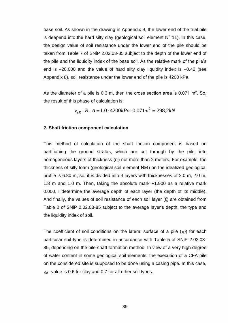
39
base soil. As shown in the drawing in Appendix 9, the lower end of the trial pile
is deepend into the hard silty clay (geological soil element No 11). In this case,
the design value of soil resistance under the lower end of the pile should be
taken from Table 7 of SNiP 2.02.03-85 subject to the depth of the lower end of
the pile and the liquidity index of the base soil. As the relative mark of the pile’s
end is –28.000 and the value of hard silty clay liquidity index is –0.42 (see
Appendix 8), soil resistance under the lower end of the pile is 4200 kPa.
As the diameter of a pile is 0.3 m, then the cross section area is 0.071 m². So,
the result of this phase of calculation is:
kNmkPaARcR 2,298071.042000.1 2
2. Shaft friction component calculation
This method of calculation of the shaft friction component is based on
partitioning the ground stratas, which are cut through by the pile, into
homogeneous layers of thickness (hi) not more than 2 meters. For example, the
thickness of silty loam (geological soil element №4) on the idealized geological
profile is 6.80 m, so, it is divided into 4 layers with thicknesses of 2.0 m, 2.0 m,
1.8 m and 1.0 m. Then, taking the absolute mark +1.900 as a relative mark
0.000, I determine the average depth of each layer (the depth of its middle).
And finally, the values of soil resistance of each soil layer (fi) are obtained from
Table 2 of SNiP 2.02.03-85 subject to the average layer’s depth, the type and
the liquidity index of soil.
The coefficient of soil conditions on the lateral surface of a pile ( cf) for each
particular soil type is determined in accordance with Table 5 of SNiP 2.02.03-
85, depending on the pile-shaft formation method. In view of a very high degree
of water content in some geological soil elements, the execution of a CFA pile
on the considered site is supposed to be done using a casing pipe. In this case,
cf –value is 0.6 for clay and 0.7 for all other soil types.

40
The whole calculation is presented in Appendix 10. Multiplying the result of this
calculation by the value of the cross section perimeter of a pile (0.94 m), I get
the result of the 2nd stage of CFA pile bearing capacity calculation:
kNmkPamhfu iicf 50418.53694.0
3. Obtaining the final result
For getting the final result of the calculation coefficient of a pile working
conditions ( c) should be determined. This coefficient depends on the type of
base soil and its degree of water saturation, in this case c=1.0. Finally, bearing
capacity Fd (kN) of a single CFA pile is calculated:
kNFd 2.802)5042.298(0.1
Thus, the result of the calculation of bearing capacity of a single CFA pile, made
in accordance with SNiP 2.02.03-85 “Pile Foundations”, is 802.2kN, or
approximately 80 tonns. The whole calculation is done without using any
computer-based programmes and is mainly based on analysis of soil
mechanics. The result should not be considered as an exact value of the pile’s
bearing capacity and needs to be verified by computer-based calculations and,
mainly, by field load testing. Thus, this value can serve as a starting point in
determining bearing capacity of a single CFA pile of a given diameter and
length.
7 SUMMARY
At the beginning of writing this thesis, the mechanism and main features of
continuous flight auger piling, which has high level of productivity and is
characterized with a high quality of shaft concreting because of supplying it
under pressure, were studied. Then, using the project materials and
documentation of the “Vita Nova” residential complex, provided by the YIT
41
Lentek JSC, other research works and theoretical manuals, I have described
and systemized the process of pile foundation design for a multi-storey
apartment building starting from the analysis of geological conditions and
finishing with structural design of the pile cap. The importance and targets of
each design stage were defined and described and also some graphic materials
are attached for illustration. These guidelines for pile foundation design for a
typical multi-storey apartment building, written in English, are useful not only for
Russian building or design companies, which often cooperate with foreign ones,
but can also be applied for further research.
This thesis also contains the elements of my engineering practice which
includes analysis of geological conditions of the site, development of idealized
geological profile and hand calculation of the bearing capacity of a single СFA
pile on the basis of Russian Building Code. This type of calculation was carried
out by me for the first time and it was not easy because of my lack of
engineering experience.
The structure/pile/soil system is highly indeterminate and nonlinear. Historically,
design methods have been based on numerous simplifying assumptions that
make the analytical efforts tractable for hand calculations. So, this hand
calculation, just like the majority of hand calculations nowadays, likely does not
show the exact value of a single СFA pile bearing capacity. The obtained result
should be defined more exactly by computing, as modern computer-based
calculations, in which many of the simplifications of the classical design
methods are no longer necessary, allow accurate enough results to be
obtained. Thus, the calculation was done to get the opportunity for approximate
evaluation of a single СFA pile bearing capacity and serves as starting point in
determination of bearing capacity of a single CFA pile of a given diameter and
length for further considerations and comparisons with other variants of piling.
42
LIST OF FIGURES
Figure 1. Classification of pile types, p. 7
Figure 2. CFA Pile Rig, p. 8
Figure 3. Effect of overexcavation using CFA piles, p. 11
Figure 4. Hole at the base of auger for concrete, p. 12
Figure 5. Residential complex “Vita Nova”. Sections’ location plan, p. 15
Figure 6. GULS and SLS for axial load on single СFA pile p. 20
Figure 7. Determination of the “conditioned” basement boundaries for pile
foundation settlement calculation, p. 28
Figure 8. Scheme of rigid connection of piles and pile cap accepted in project of
“Vita Nova” residential complex p. 30
Figure 9. СFA pile bearing capacity components p. 38
43
REFERENCES
Apartment Building with Built-in and Attached Premises at Mebelnaya street, parcel No 1. Project. Volume 1. Common Data. 2007. Genproject Ltd.
Apartment Building with Built-in and Attached Premises. Project. Volume 1. Common Data. 2007. JUVA RUS Ltd. Bartolomei A.A. 1995. Pile Foundation Engineering. Soil Mechanics and Foundation Engineering, Vol. 32, No. 3, p.73 Baxter D.J. 2009. Innovation in the Design of Continuous Flight Auger and Bored Displacement Piles. Leicestershire: Centre for Innovative and Collaborative Engineering, Loughborough University Dalmatov B.I. 2002. Grounds and Foundations. Saint-Petersburg: ACB GEOTECHNICAL ENGINEERING CIRCULAR NO.8. Design and Construction of Continuous Flight Auger (CFA) Piles. 2007. Maryland: GeoSyntec Consultants Mangushev R.A., Ershov A.V, Osokin A.I. Modern Piling Technologies. 2007. St.Petersburg State University of Architecture and Civil Engineering SNiP 2.02.03-85 Pile Foundations. 1995. Moscow: Ministry of Construction of Russian federation. SNiP 2.02.01-83* Bases of Buildings and Structures. 1995. Moscow: Ministry of Construction of Russian federation. Technical Report on Geological Investigations, Performed for the Design of Apartment Building with Built-in and Attached Premises at Mebelnaya street, parcel No 1. 2007. LenTISIZ JSC. www.franki.com.au/PDF/Dynamic_Load_Test (Accessed on 20 April 2010)