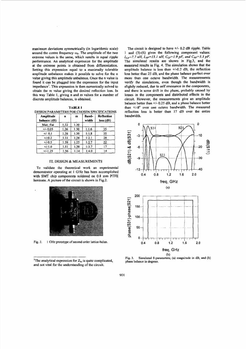
WE2D-4 Design of Broadband Lumped Element Balms Dan Kuylenstierna, and Peter Linnkr Senior Member, IEEE Micro wave Electronics Laboratory, C halme rs University of Technology, SE-412 96 Goteborg, Sweden Absfrort - h i s paper reports on a small size broadband lumped element b alun suitable for integ ration in MMICa The design is a u extension of the well known lattice balun, whic h indepe ndent o f frequency has 180’ phase difference heween the output ports, but suffers from a narrow amplitude bandwidth. It is shown how the amplitude bandwidth of the latti ce bahm may be improved by replacing indu ctors with low- pass T-sectio ns, and the capac itor s with high-pass T-sectlons. Scalable closed-form design equations for var ious bandwtdths ar e derived . To validate the concep t a prototype operating at 1 GH z has been fabricated with SMT chip components soldered on a PTFE laminate. It exhibits amplitude balance better than M.25 dB and phase balance better than + Sq over more than one octave bandwidth. The effective chiparea is 7 x 9 mm’. I. INTRODUCTTON The balun is a component that transforms between single ended and balanced signals. It plays an important role in modem microwave technology, where it is increasingly used for balanced amplifiers, balanced mixers, and antennas for instance [I]. A badly designed balun may ruin the operation of the complete system, so it is worth to put some efforts in its design. Traditionally baluns operating at higher frequencies are designed in distributed versions, such as the Marchand balun [2]. However, at low fr equencies distributed designs consume too much of the expensive chip area, and are therefore not suitable fo r MMICs. To reduce the chip area lumped element baluns ma y be used. These can be divided into four main categories: 1) Active baluns [3], 2) planar transformer baluns [4], 3) lumped element 180” hybrids [5], and 4) lumped element filter baluns [6]-[7]. This paper deals with the fourth category. The simplest possible filter balun uses dual low-pass and high-pass L- sections and is known as the lattice bal un [6], or out-of- phase power splitter. It is popular in narrow banded MMICs. For instance a double balanced mixer using the lattice balun is presented in [7]. n the same issue, the same author also presents a broadband double balanced mixer, using a fifth order out-of-phase power splitter with compensating filters between the output ports and ground [8]. This paper has been the main initiator to this work. Some considerations of the filth order filters in [ 8] show that many components are redundant, due to resonance at the centre frequency. If the “redundant” elements are omitted the filters reduce to third order T-filters. Comparing the low-pass filters to inductors and the high- pass filters to capacitors it is found that the remaining circuit has the same symmetry as the lattice balun. For this reason it is referred to as a second order lattice balun. Analysis of the second orde r lattice balun results in closed form analytical expressi ons for component values giving a certain amplitude balance and a certain bandwidth. 111. ANALYSIS It is well known that low-pass and high-pass ladder networks, also known as synthetic transmission lines, ma y be used to replace distributed transmission lines to form lumped element hybrids [SI. It is possible to use both, low-pass ladder networks, representing normal distributed lines that support forward waves, and high-pass ladder networks that support backward waves [9]. The use of dual low-pass and high-pass ladder networks makes it possible to design some circuits which do not have any distributed analogies. One example is the out-of-phase power splitter, which uses dual high-pass and low-pass filters, a quarter wavelengths long at the centre frequency. Since the low-pass filter supports forward waves and the between the output ports is 180” at the centre frequency. The simplest possible (first order) out-of-phase power splitter, Fig.l a, uses low-pass and high-pass L-sections for the two filters. The component values are determined from the desired centre frequency and the fact that the two filters act as quarter wave impedance transformers. For a balun transforming from an unbalanced source of impedance Z, to a balanced load of impedance ZZ, the component values are: L = - JZZ, (1) 0 0 (2) 1 c = JTzowo where Z , is the system impedance, and o o he centre frequency. Furthmore, it is also possible to design baluns with inherent impedance transformation. 0-7803-8331-1/04/$20.00 0 W IEEE 899 , 2004 IE EE MTT- S Digest