design of boilers piping - national board of boiler and ... only/technical...
TRANSCRIPT

Design of Boilers and Power Piping
When determining the scope of the code of construction, review the following:
• Section I, Preamble• ASME B31.1, Chapter 1, Scope and Definitions
These paragraphs, and Manufacturer’s documents establish the boundaries to which the ASME Code applies.
1NBIC, Part 3, 3.2.4(b)

Design of Boilers and Power Piping
ASME Code Section I (Power Boilers) can be thought of as a “System Code Section” and includes by reference, ASME B31.1 (Power Piping) with specific rules for Boiler External Piping.
Section I Scope•Boilers with an MAWP greater than 15 psi steam or 160 psi water or 250° F water.
2

ASME Section I Preamble

Design of Boilers and Power Piping
4

Design of Boilers and Power Piping
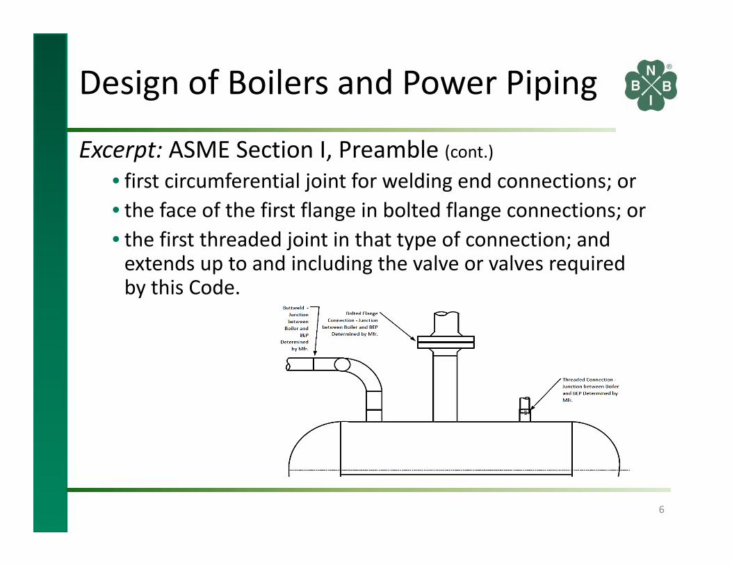
Excerpt: ASME Section I, Preamble• The Scope of jurisdiction of Section I applies to the boiler proper and boiler external piping. Superheaters, economizers, and other pressure parts connected to the boiler without intervening valves shall be considered as part of the boiler proper, and their construction shall conform to ASME Section I rules.
• Construction rules for materials, design, fabrication, installation, and testing of the boiler external piping are contained in ASME B31.1, Power Piping.
5
Design of Boilers and Power Piping
Excerpt: ASME Section I, Preamble (cont.) • first circumferential joint for welding end connections; or• the face of the first flange in bolted flange connections; or• the first threaded joint in that type of connection; and extends up to and including the valve or valves required by this Code.
6

Design of Boilers and Power Piping
The Boiler Manufacturer has to define where the change from Boiler to Boiler External Piping and Boiler External Piping to Non‐Boiler External Piping exists.
This is typically done using Piping and Instrumentation Diagrams (P&ID’s) or drawings depicting where the terminal points occur.
The terminal points are not required to be shown on the Manufacturer’s Data Report. They are required to be provided to the AI.
7
Pressure Controls
vvvv
v v
Pump
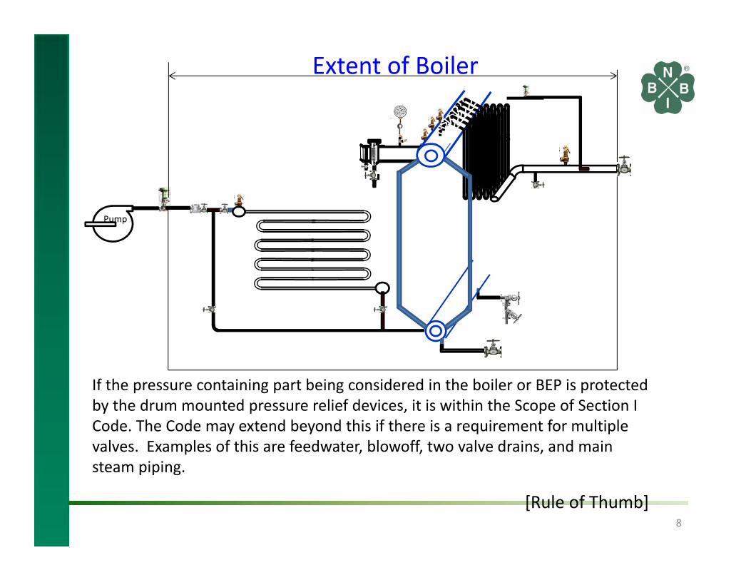
If the pressure containing part being considered in the boiler or BEP is protected by the drum mounted pressure relief devices, it is within the Scope of Section I Code. The Code may extend beyond this if there is a requirement for multiple valves. Examples of this are feedwater, blowoff, two valve drains, and main steam piping.
[Rule of Thumb]8
Extent of Boiler

BEP
BEP
BEP
NBEP
PG‐61
122.1.3(A.2) not less thanpressure required to feed the boiler
Single Boiler
Two or More Boilers Fed From One Common Source
[Section I PG‐58.3.3, PG‐58.3.4, PG‐61, & [B31.1 122.1.3(A.2)] 9
Boiler Manufacturer Determines where BEP begins Welds
Welds
Feedwater

Section I Isolatable EconomizerBEP
BEP
BEP
BEP
Pressure Relief Valve (V) Required
Intervening valves within the scope of the BEP
BoilerStainless steel (3XX) is prohibited.
Design Pressure Economizer = Pressure relief device set pressure
[Section I Preamble, PG‐5.5, PG‐67.2.1.6 & PG‐69.1.6] 10

Pressure Relief Valve (UV) Required
Scope LimitOf Section I
Economizer, external to the boiler, (with or without a three valve bypass) shall be constructed in accordance with ASME Section VIII, Div. 1, including Special Service “DF” when the heat transfer surfaces are exposed to the products of combustion. Flame is not a consideration.
All piping outside of Section I Scope will be Non‐boiler external piping. (NBEP)
Boiler
Section VIII, Div. 1 Economizer or Heat Exchanger External of Section I Scope
Design Pressure Economizer = Pressure relief device set pressure
UDF
[ASME Section VIII, Div. 1, paragraphs U‐1(h), UW‐2(d) & UG‐125] 11
BEP
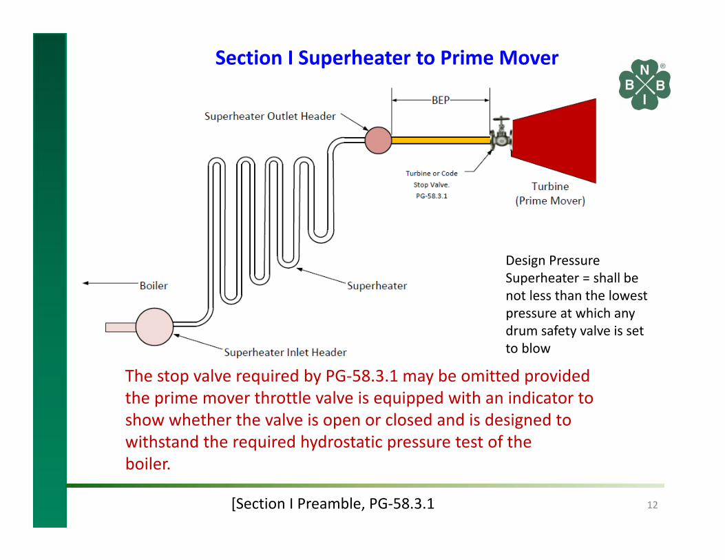
Section I Superheater to Prime Mover
Design Pressure Superheater = shall benot less than the lowest pressure at which any drum safety valve is set to blow
[Section I Preamble, PG‐58.3.1 12
The stop valve required by PG‐58.3.1 may be omitted provided the prime mover throttle valve is equipped with an indicator to show whether the valve is open or closed and is designed to withstand the required hydrostatic pressure test of theboiler.

Design of Boilers and Power Piping
Section IPG‐58.3 Boiler External Piping
• The Code Jurisdictional Limits of the boiler external piping systems are shown in Figure PG‐58.3.1.
• The materials, design, fabrication, installation and testing shall be in accordance with B31.1, Power Piping.
B31.1, Scope and DefinitionsParagraph 100.1.2
• The terminal points themselves are considered part of the boiler external piping.
13