design of a thermal precipitator for the characterization ... · design of a thermal precipitator...
TRANSCRIPT

Marit MeyerGlenn Research Center, Cleveland, Ohio
Design of a Thermal Precipitator for theCharacterization of Smoke Particles FromCommon Spacecraft Materials
NASA/TM—2015-218746
June 2015
https://ntrs.nasa.gov/search.jsp?R=20150010719 2018-06-02T03:45:18+00:00Z

NASA STI Program . . . in Profi le
Since its founding, NASA has been dedicated to the advancement of aeronautics and space science. The NASA Scientifi c and Technical Information (STI) Program plays a key part in helping NASA maintain this important role.
The NASA STI Program operates under the auspices of the Agency Chief Information Offi cer. It collects, organizes, provides for archiving, and disseminates NASA’s STI. The NASA STI Program provides access to the NASA Technical Report Server—Registered (NTRS Reg) and NASA Technical Report Server—Public (NTRS) thus providing one of the largest collections of aeronautical and space science STI in the world. Results are published in both non-NASA channels and by NASA in the NASA STI Report Series, which includes the following report types: • TECHNICAL PUBLICATION. Reports of
completed research or a major signifi cant phase of research that present the results of NASA programs and include extensive data or theoretical analysis. Includes compilations of signifi cant scientifi c and technical data and information deemed to be of continuing reference value. NASA counter-part of peer-reviewed formal professional papers, but has less stringent limitations on manuscript length and extent of graphic presentations.
• TECHNICAL MEMORANDUM. Scientifi c
and technical fi ndings that are preliminary or of specialized interest, e.g., “quick-release” reports, working papers, and bibliographies that contain minimal annotation. Does not contain extensive analysis.
• CONTRACTOR REPORT. Scientifi c and technical fi ndings by NASA-sponsored contractors and grantees.
• CONFERENCE PUBLICATION. Collected papers from scientifi c and technical conferences, symposia, seminars, or other meetings sponsored or co-sponsored by NASA.
• SPECIAL PUBLICATION. Scientifi c, technical, or historical information from NASA programs, projects, and missions, often concerned with subjects having substantial public interest.
• TECHNICAL TRANSLATION. English-language translations of foreign scientifi c and technical material pertinent to NASA’s mission.
For more information about the NASA STI program, see the following:
• Access the NASA STI program home page at http://www.sti.nasa.gov
• E-mail your question to [email protected] • Fax your question to the NASA STI
Information Desk at 757-864-6500
• Telephone the NASA STI Information Desk at 757-864-9658 • Write to:
NASA STI Program Mail Stop 148 NASA Langley Research Center Hampton, VA 23681-2199

Marit MeyerGlenn Research Center, Cleveland, Ohio
Design of a Thermal Precipitator for theCharacterization of Smoke Particles FromCommon Spacecraft Materials
NASA/TM—2015-218746
June 2015
National Aeronautics andSpace Administration
Glenn Research CenterCleveland, Ohio 44135

Acknowledgments
Marit Meyer: Research of previous devices, aerosol physics calculations, general design and geometry parameters, fi nite element modeling resulting in fi nal design parameters, initial testing and fi nal use in smoke experiments. Daniel Gotti (National Center for Space Exploration Research, NSCER): CAD design and modeling in ProE, thermal analysis and thermal design, packaging, hardware selection and assembly of TP, instrumentation with thermocouples, assistance with initial testing. Victoria Bryg (National Center for Space Exploration Research, NSCER): Choice & preparation of microscopy substrates, microscopy (SEM and TEM).
Available from
Trade names and trademarks are used in this report for identifi cation only. Their usage does not constitute an offi cial endorsement, either expressed or implied, by the National Aeronautics and
Space Administration.
Level of Review: This material has been technically reviewed by technical management.
NASA STI ProgramMail Stop 148NASA Langley Research CenterHampton, VA 23681-2199
National Technical Information Service5285 Port Royal RoadSpringfi eld, VA 22161
703-605-6000
This report is available in electronic form at http://www.sti.nasa.gov/ and http://ntrs.nasa.gov/

NASA/TM—2015-218746 1
Design of a Thermal Precipitator for the Characterization of Smoke Particles From Common Spacecraft Materials
Marit Meyer
National Aeronautics and Space Administration Glenn Research Center Cleveland, Ohio 44135
Abstract
A thermal precipitator (TP) was designed to collect smoke aerosol particles for microscopic analysis in fire characterization research. Information on particle morphology, size and agglomerate structure obtained from these tests supplements additional aerosol data collected. Modeling of the thermal precipitator throughout the design process was performed with the COMSOL Multiphysics finite element software package, including the Eulerian flow field and thermal gradients in the fluid. The COMSOL Particle Tracing Module was subsequently used to determine particle deposition. Modeling provided optimized design parameters such as geometry, flow rate and temperatures. The thermal precipitator was built and testing verified the performance of the first iteration of the device. The thermal precipitator was successfully operated and provided quality particle samples for microscopic analysis, which furthered the body of knowledge on smoke particulates. This information is a key element of smoke characterization and will be useful for future spacecraft fire detection research.
Introduction
Characterization of the smoke from pyrolysis of common spacecraft materials provides insight for the design of future smoke detectors and post-fire clean-up equipment on the International Space Station. Real-time measurements of smoke particles in terms of number and mass concentration are useful, however, a wealth of additional information can be obtained by microscopy techniques. Magnified images show morphology, degree of particle agglomeration and also provide insight into particle formation mechanisms. Further techniques such as energy dispersive X-ray spectroscopy (EDS) give elemental composition of individual particles. An appropriate sampling method must be used to obtain quality microscopy results, and thermophoretic sampling directly on microscopy substrates is preferred to minimize handling and potential contamination. Thus, an appropriate thermal precipitator (TP) was created to augment existing spacecraft smoke data.
The thermal precipitator design was targeted towards smoke particles from typical oxidative pyrolysis tests at NASA’s White Sands Test Facility (WSTF) conducted to challenge and verify performance of post-fire cleanup equipment under development for spacecraft (Meyer et al. 2013). These tests were characterized by aerosol mass and number concentrations ranging from 40 to 70 mg/m3 and 1105 to 1106 particles/cm3 and particle diameters ranging from 100 to 1000 nm. The goal of characterizing the smoke particles by microscopy was twofold: to verify that a repeatable fire challenge was produced in the facility and to determine the particle morphology and elemental composition resulting from various fuels and temperatures. The intention was not to perform a size distribution analysis, so numerical modeling was restricted to the 100 to 1000 nm particle size range. Sizes outside of this size range were captured, as seen in the microscopy results, however, there was no attempt to calculate deposition efficiency of the device beyond the design range. There was also no requirement to make the TP compact, low power or portable, in the first iteration effort.

NASA/TM—2015-218746 2
Existing Thermal Precipitator Designs
At the time of the early TP design phase, there was no thermal precipitator commercially available, and it was determined that an original device should be created and tailored to WSTF smoke testing. A number of references were consulted in order to gain insight from successful instruments, and some design rules-of-thumb emerged based on the thermal precipitators listed in Table 1. Note that the devices are listed in order of increasing particle size ranges which were either documented as design goals or the range of particle sizes tested in experiments reported in the references.
The basic design trade is between the magnitude of the thermal gradient and the flow rate—which determines residence time and thus deposition efficiency of the desired size ranges. Notional geometry of the phenomenon of thermophoretic deposition is shown in Figure 1, which shows particles traveling axially through a thermal gradient directed perpendicularly to the flow path between two parallel flat surfaces. In a thermal precipitator, the thermophoretic force acting on the particle must drive it to the cold collection substrate before it reaches the end of the thermal gradient region in the device. An added complication for the smallest particles is the effect of diffusion, which causes particle losses that increase with residence time in the TP, and simultaneously, residence time is also increased by slip. This is evident from the first three devices listed in the table, which have extremely high flow rates for short residence times, coupled with very small gaps and the largest thermal gradients, for maximum thermophoretic force leading to deposition of smaller particles.
Several designs in Table 1 use a transmission electron microscope (TEM) grid as the collection substrate to facilitate microscopic analysis. A larger collection substrate allows more latitude in the design parameters for thermal gradients and flow rates required for high collection efficiencies. The TP designs of Azong-Wara and Tsai and Lu use larger collection substrates (4 and 74 times larger area than a TEM grid, respectively) and thus can tolerate lower flow rates and a smaller thermal gradient and still achieve a sufficient residence time for high deposition rates. Collecting particles directly on a microscopy substrate is preferable, so the goal of this TP design was to use a scanning electron microscopy (SEM) specimen holder, called a stub, integrated into the cold surface.
The TP design for smoke particles has a much larger desired size range than the other devices in Table 1. Since the aerosol physics influencing thermal precipitator design is determined based on the Knudsen number, the dynamics of larger particles in a thermal precipitator can be modeled using the
TABLE 1.—DESIGN PARAMETERS OF OTHER THERMAL PRECIPITATORS IN THE LITERATURE Reference Thermal gradient,
K/mm Gap, mm
Flow rate, cc/min
Intended particle size range,
nm
Collection substrate
Wen & Wexler 2007 500 0.1 1500 less than 10 TEM grid Maynard 1995 1000 0.15 1010 less than 100 TEM grid Lorenzo et al. 2007 400 0.3 2000 15 to 300 TEM grid Azong-Wara et al. 2009 15 1.25 2 up to 300 206 mm plate Tsai & Lu 1995 83.7 and 50.3 0.38 400 40 to 500 37.1 cm plate Current TP design 56 1.25 110 100 to 1000 SEM stub with TEM grids

NASA/TM—2015-218746 3
following formulas. When the particle size is larger than the mean free path of the surrounding air (dp λ, or Kn is small), then the thermophoretic force on a particle, Fth, is given by (Hinds, 1999)
pg
pth T
THdF
2
9 2
(1)
where μ is the viscosity of air, ρg is the density of the surrounding gas (air), Tp is the particle absolute temperature (the temperature of the aerosol, typically considered to be ambient temperature) and T is the thermal gradient in the gas. The coefficient H accounts for a temperature gradient within the particle and thus depends on particle diameter and is given by
ppa
ppa
p dkk
dkk
d
H8.821
4.4
61
1 (2)
where ka is the thermal conductivity of the air and kp is the thermal conductivity of the particle. The thermophoretic velocity for particle diameters larger than the mean free path of air is given by (Hinds, 1999)
pg
cth T
THCV
2
3 (3)
where the Cunningham slip correction factor, Cc is included. Ambient pressure is an influencing variable by way of the gas density in the force and velocity equations. Thus, the thermophoretic force was enhanced by approximately 20 percent at WSTF, considering the effect of lower pressure, which is 85150 Pa (0.84 atm) owing to the altitude in Las Cruces, New Mexico. To estimate the thermal conductivity of pyrolysis smoke particles, they were assumed to consist of re-condensed polymer vapors on small primary particles. An average of nine representative WSTF fuel polymer materials ranging from 0.12 to 0.3 W/m-K was used to obtain the value kp = 0.19 W/m-K used in calculations and modeling. At larger sizes, the effect of the particle material is more pronounced. Figure 2 shows calculations of the thermophoretic force (Eq. (1)) versus particle size, and it is evident that the thermal conductivity of salt

NASA/TM—2015-218746 4
particles, which has approximately 25 times the thermal conductivity of air, results in a smaller force on particle sizes larger than 500 nm, when compared to the polymer smoke. Particle temperature is assumed to be equilibrated with the typical WSTF smoke chamber temperature of 40 C (313 K).
Finite Element Modeling to Narrow Design Space
A design space consists of all possible configuration options to achieve an engineering outcome, which is narrowed or optimized based on constraints of the laws of physics and available hardware to generate conditions required to achieve the outcome. Finite element modeling is a rapid and cost-effective method of exploring design spaces, so that interconnected design parameters can be optimized virtually, and fully functioning hardware can be built on the first iteration. This approach was used in the TP design, with the COMSOL Multiphysics software package, version 4.2. This product is a finite element analysis (FEA) solver which provides the ability to couple various physical phenomena described by the term “multiphysics.”
First, an Eulerian numerical model was created to represent laminar fluid dynamics and the heat transfer in the fluid of the device. Subsequently, the COMSOL Multiphysics Particle Tracing Module was used to apply user-defined forces on particles for Lagrangian simulations based on previous Eulerian solutions. Thus, the iterative design approach was to solve the Eulerian model, then calculate thermophoretic force as a function of particle size, parametrically modify the particle forces in the model (including slip-corrected Stokes drag) and simulate monodisperse particle deposition in the TP geometry through multiple simulations over the particle size range of interest. After a number of modeling iterations, the design space was suitably narrowed and one of many possible optimized solutions was chosen for the final TP configuration.
The COMSOL fluid flow interfaces uses the Navier-Stokes equations, for incompressible flow consisting of conservation of mass
0 u (4)
(where u is the three-dimensional fluid velocity vector) and conservation of momentum
pt
uuuu
ff2 (5)
where p is pressure. The COMSOL heat transfer in fluids model uses the simplified heat equation
TkTCt
TC apgpg
(6)
where Cp is the fluid heat capacity at constant pressure and T is the absolute temperature of the air. The particle tracing module uses Newton’s second law to define the motion of a particle, which
includes the two important user-defined forces for the TP
dthdt
dm FF
x
2
2 (7)
where the thermophoretic force is in the direction of the thermal gradient, given by Equation (1). Fd is the Stokes drag given by
c
ppd C
d uuF
3 (8)
NASA/TM—2015-218746 5
where up is the three-dimensional particle velocity vector, defined as the fluid velocity in the initial conditions (at time = 0 of the particle trajectory). No additional body forces (such as gravity) were imposed on the particles.
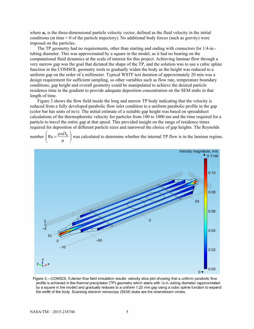
The TP geometry had no requirements, other than starting and ending with connectors for 1/4-in.-tubing diameter. This was approximated by a square in the model, as it had no bearing on the computational fluid dynamics at the scale of interest for this project. Achieving laminar flow through a very narrow gap was the goal that dictated the shape of the TP, and the solution was to use a cubic spline function in the COMSOL geometry tools to gradually widen the body as the height was reduced to a uniform gap on the order of a millimeter. Typical WSTF test duration of approximately 20 min was a design requirement for sufficient sampling, so other variables such as flow rate, temperature boundary conditions, gap height and overall geometry could be manipulated to achieve the desired particle residence time in the gradient to provide adequate deposition concentration on the SEM stubs in that length of time.
Figure 3 shows the flow field inside the long and narrow TP body indicating that the velocity is reduced from a fully developed parabolic flow inlet condition to a uniform parabolic profile in the gap (color bar has units of m/s). The initial estimate of a suitable gap height was based on spreadsheet calculations of the thermophoretic velocity for particles from 100 to 1000 nm and the time required for a particle to travel the entire gap at that speed. This provided insight on the range of residence times required for deposition of different particle sizes and narrowed the choice of gap heights. The Reynolds
number
huD
Re was calculated to determine whether the internal TP flow is in the laminar regime.

NASA/TM—2015-218746 6
The hydraulic diameter, Dh, is twice the height of the TP body, as the fluid can be considered to be flowing between two plane parallel surfaces where the gap height is much less than the width. For all design iterations, Re was well below the critical value of 2300 for the full range of each design parameter considered, typically below 50.
Simple temperature boundary conditions were applied to simulate various cold and hot plate areas in the TP model, creating a gradient on the order of 50 to 100 C/m, an initial estimate based on the design of Tsai and Lu (Table 1). Although a more detailed thermal model can easily be made in COMSOL, there was no benefit for the TP geometry design iterations. Subsequent thermal design was perfected through experiments and thermocouple measurements, as contact conductances between parts of the final assembly were unknown. The temperature gradient is the only Eulerian model input needed for the thermophoretic force which was applied in the z-direction (vertical axis in figures) using Equation (1). Stokes drag (a function of the three-dimensional velocity field solved in the Eulerian simulation) was applied on particles in the x- and y- and z-directions according to Equation (8).
Flow field iterations were used as inputs for particle trajectory simulations corresponding to 100 nm, 500 and 1000 nm spherical particles subjected to Stokes drag and material-specific thermophoretic forces.
Figure 4 shows COMSOL Lagrangian particle trajectory simulation results with moving particles (left) and deposition pattern (right) of 1000 particles with 100 nm diameter, accounting for particle thermal conductivity in the vertical thermophoretic force and three-dimensional Stokes drag. The deposition pattern does not reach the SEM stubs (circles), so this intermediate set of design parameters was not accepted. Subsequent to this simulation, the thermal gradient was reduced in the model so that particle deposition would be delayed and cover the circular SEM stubs further downstream.
Overall, COMSOL modeling narrowed the design space significantly. Simulation results showed that an elongated TP body and a correspondingly longer section of constant thermal gradient would allow for longer residence time and deposition of the size range of interest. Additionally, placing two stubs in series provided the ability to collect a larger size range of particles. Final variables in the TP design are given in the last entry of Table 1. The COMSOL model was considered a design tool, not an end in itself, and once the parameters were defined within the realm of available heaters, coolers and pumps, focus was placed on the physical TP design and testing to complete the project.
NASA/TM—2015-218746 7
Mechanical and Thermal Design
The thermophoretic force on a particle subjected to a temperature gradient is directed towards the cold surface, which in this TP design is the collection substrate for microscopy, a 15 mm diameter aluminum SEM specimen mount (Hitachi M4) with threaded hole. By making two stubs in series, the collection area is increased and thus a larger range of particle sizes are deposited. A portion of each stub surface was covered with a strip of carbon two-sided sticky tape in the flow direction, in order to attach 3.01 mm TEM grids enabling multiple types of electron microscopy. The carbon tape provided an alternate surface for particle deposition in addition to the aluminum stub surface. Carbon tape backing was peeled back slightly to adhere the TEM grids and then pressed back down to maintain cleanliness of the tape surface until testing took place. The tape backing was removed prior to each sampling test after the new clean stub was installed.
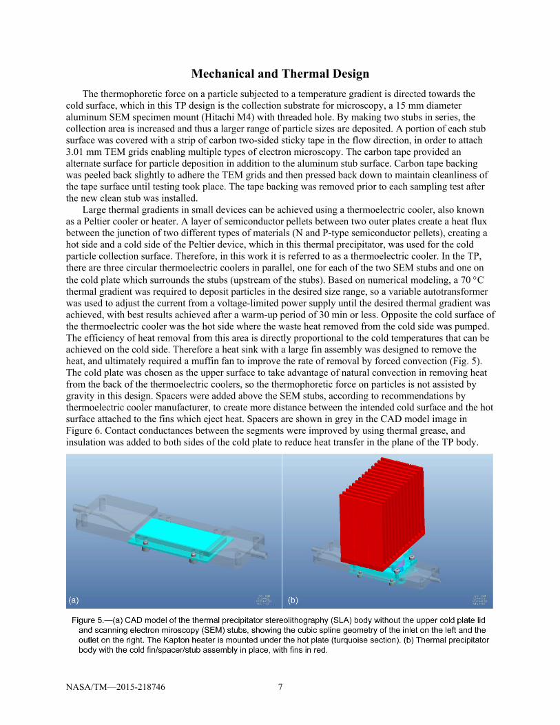
Large thermal gradients in small devices can be achieved using a thermoelectric cooler, also known as a Peltier cooler or heater. A layer of semiconductor pellets between two outer plates create a heat flux between the junction of two different types of materials (N and P-type semiconductor pellets), creating a hot side and a cold side of the Peltier device, which in this thermal precipitator, was used for the cold particle collection surface. Therefore, in this work it is referred to as a thermoelectric cooler. In the TP, there are three circular thermoelectric coolers in parallel, one for each of the two SEM stubs and one on the cold plate which surrounds the stubs (upstream of the stubs). Based on numerical modeling, a 70 C thermal gradient was required to deposit particles in the desired size range, so a variable autotransformer was used to adjust the current from a voltage-limited power supply until the desired thermal gradient was achieved, with best results achieved after a warm-up period of 30 min or less. Opposite the cold surface of the thermoelectric cooler was the hot side where the waste heat removed from the cold side was pumped. The efficiency of heat removal from this area is directly proportional to the cold temperatures that can be achieved on the cold side. Therefore a heat sink with a large fin assembly was designed to remove the heat, and ultimately required a muffin fan to improve the rate of removal by forced convection (Fig. 5). The cold plate was chosen as the upper surface to take advantage of natural convection in removing heat from the back of the thermoelectric coolers, so the thermophoretic force on particles is not assisted by gravity in this design. Spacers were added above the SEM stubs, according to recommendations by thermoelectric cooler manufacturer, to create more distance between the intended cold surface and the hot surface attached to the fins which eject heat. Spacers are shown in grey in the CAD model image in Figure 6. Contact conductances between the segments were improved by using thermal grease, and insulation was added to both sides of the cold plate to reduce heat transfer in the plane of the TP body.

NASA/TM—2015-218746 8
A Kapton (DuPont, Wilmington, DE) heater was connected to the hot plate with thermal grease opposite of the cold aluminum plate and stubs. There was no direct control of temperature as the required thermal gradient was consistently achieved once the heat removal was improved by forced convection. Permanent type K thermocouples were installed at the hot plate and the cold plate to provide real-time information on the gradient and to indicate when the thermal precipitator had fully warmed up (reached equilibrium). Preliminary tests were performed with 1000, 670, and 105 nm polystyrene latex (PSL) test aerosol spheres and with polydisperse NaCl aerosol and microscopy verified that good deposition was obtained for all sizes, which validated the thermal design of the precipitator. Based on Figure 2, the thermophoretic force on NaCl particles is expected to be weaker than that of polymer pyrolysis smoke particles, so improved collection efficiency was expected in the actual smoke testing. Additional extended durations of testing were performed with a zero filter (small HEPA filter) at the inlet of the thermal precipitator and a condensation particle counter (CPC) at the outlet in order to verify that particles were not generated from within the device itself. In this test, particle-free air entered the TP and the aerosol number concentration measured by the CPC was verified to be zero. Subsequent microscopy also showed no particles on the SEM stubs.
Figure 6 shows a cut-away view of the thermal precipitator CAD model. The aerosol outlet is connected to a zero filter followed by a small pump. This prevents particles from entering the pump, however, acid gases which are products of the WSTF pyrolysis tests will still enter the pump, so it must be monitored for performance and replaced when internal parts are compromised by the harsh environment.
NASA/TM—2015-218746 9
The SEM stubs were numbered 1 and 2, and there were slight differences in the temperatures of the
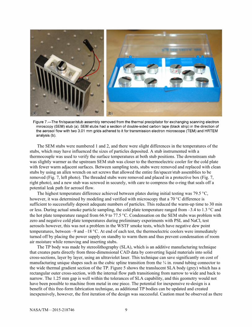
stubs, which may have influenced the sizes of particles deposited. A stub instrumented with a thermocouple was used to verify the surface temperatures at both stub positions. The downstream stub was slightly warmer as the upstream SEM stub was closer to the thermoelectric cooler for the cold plate with fewer warm adjacent surfaces. Between sampling tests, stubs were removed and replaced with clean stubs by using an allen wrench on set screws that allowed the entire fin/spacer/stub assemblies to be removed (Fig. 7, left photo). The threaded stubs were removed and placed in a protective box (Fig. 7, right photo), and a new stub was screwed in securely, with care to compress the o-ring that seals off a potential leak path for aerosol flow.
The highest temperature difference achieved between plates during initial testing was 79.5 C, however, it was determined by modeling and verified with microscopy that a 70 C difference is sufficient to successfully deposit adequate numbers of particles. This reduced the warm-up time to 30 min or less. During actual smoke particle sampling, the cold plate temperature ranged from –3.4 to 1.3 C and the hot plate temperature ranged from 66.9 to 77.5 C. Condensation on the SEM stubs was problem with zero and negative cold plate temperatures during preliminary experiments with PSL and NaCl, test aerosols however, this was not a problem in the WSTF smoke tests, which have negative dew point temperatures, between –9 and –18 C. At end of each test, the thermoelectric coolers were immediately turned off by placing the power supply on standby to warm them and thus prevent condensation of room air moisture while removing and inserting stubs.
The TP body was made by stereolithography (SLA), which is an additive manufacturing technique that creates parts directly from three-dimensional CAD data by converting liquid materials into solid cross-sections, layer by layer, using an ultraviolet laser. This technique can save significantly on cost of manufacturing unique shapes such as the cubic spline transition from the ¼ in. round tubing connector to the wide thermal gradient section of the TP. Figure 5 shows the translucent SLA body (grey) which has a rectangular outer cross-section, with the internal flow path transitioning from narrow to wide and back to narrow. The 1.25 mm gap is well within the tolerances of SLA capability, and this geometry would not have been possible to machine from metal in one piece. The potential for inexpensive re-design is a benefit of this free-form fabrication technique, as additional TP bodies can be updated and created inexpensively, however, the first iteration of the design was successful. Caution must be observed as there

NASA/TM—2015-218746 10
is a tendency of SLA parts to warp, shrink or sag over time. Therefore, before using the TP, a leak-check is performed to assure that the seals are intact.
An aluminum housing was constructed to contain and protect all wires and parts. Figure 8 shows the outer housing with the fan and the hinged lid opened revealing the heatsinking fins. The aerosol inlet is below the fan, and the outlet is at the opposite end of the housing.
Conclusion
The thermal precipitator was successfully built after finite element modeling iteratively determined key design parameters. Testing verified the performance of the first iteration of the device and no subsequent design modifications were necessary. The thermal precipitator was successfully operated and provided quality particle samples for microscopic analysis, which furthered the body of knowledge on smoke particulates. Morphology and chemical composition information are important aspects of smoke characterization and will be useful for future spacecraft fire detection research.
History
TP design conceived, modeled and iterated starting June 2011 Constructed November 2011 Tested December 2011 and January 2012 Successfully used February 2012
References
Azong-Wara, N., et al.: Optimisation of a Thermophoretic Personal Sampler for Nanoparticle Exposure Studies. J. Nanoparticle Res., vol. 11, 2009, pp. 1611–1624.
COMSOL 4.2a Multiphysics User’s Guide: COMSOL, Inc., Burlington, MA, 2011. Hinds, W.C.: Aerosol Technology. Second ed., Wiley Interscience, New York, 1999. Lorenzo, R., et al.: A Thermophoretic Precipitator for the Representative Collection of Atmospheric
Ultrafine Particles for Microscopic Analysis. Aerosol Sci. Technol., vol. 41, no. 10, 2007, pp. 934−943.

NASA/TM—2015-218746 11
Maynard, A.D.: The Development of a New Thermophoretic Precipitator for Scanning-Transmission Electron-Microscope Analysis of Ultrafine Aerosol-Particles. Aerosol Sci. Technol., vol. 23, 1995, pp. 521–533.
Meyer, M.E., et al.: Materials Combustion Testing and Combustion Product Sensor Evaluations in FY12. AIAA−2013−3432, 2013.
Tsai, C.J.; and Lu, H.C.: Design and Evaluation of a Plate-To-Plate Thermophoretic Precipitator. Aerosol Sci. Technol., vol. 22, 1995, pp. 172–180.
Wen, J.; and Wexler, A.S.: Thermophoretic Sampler and Its Application in Ultrafine Particle Collection. Aerosol Sci. Technol., vol. 41, no. 6, 2007, pp. 624−629.


