design of a specialized airborne-infection ... of a specialized airborne-infection-isolation suite...
TRANSCRIPT

DESIGN OF A SPECIALIZED AIRBORNE-INFECTION-ISOLATION SUITE
FEBRUARY 2011 HPAC ENGINEERING 25
FEBRUARY 2011 A Penton Publication
HEATING/PIPING/AIR CONDITIONING
ENGINEERING
EGB: Benefits of
Whole-Building Design
Utilizing Plant Effluent
for Heating and Cooling
Excerpt from the book "The
EcologicalEngineer:
Glumac":Kelley Engineering
Center

FEBRUARY 2011 HPAC ENGINEERING
Design of a Specialized Airborne-Infection
Isolation Suite
Lessons learned from the design of
new National Institutes of Health facility
By FARHAD MEMARZADEH,PhD, PE,
and DEBORAH E.WILSON,DrPH,CBSP,
NationalInstitutes of Health,
Bethesda,Md.,
and KRISHNAN RAMESH,PE,
Affiliated Engineers Inc.,
Rockville, Md.
A biocontainment patient-care unit (BPCU) is a facil
i ty d igned and operated to maximize patient care with
apprcopriate infection-control practices and procedures.
A BPCU is secure, is physically separated from other
patient-care areas, and has special air-handling systems.1
The National Institutes of Health's
new Special Clinical Studies Unit (SCSU)
in Bethesda, Md., is a rughly specialized
BPCU, housing patients with extremely
infectious diseases transmissible by
respiratory aerosolization, direct con
tact with primary body fluids, or dried
infectious particles from body fluids.
The SCSU has three patient rooms
plus an occupational-exposure isola
tion room (OETR). It is equipped to meet
all clinical-care needs, including basic
medical observation, minor surgical
procedures, and intensive care. Thus,
ria used for the SCSU, wruch can be applied for any other
type of airborne-infection-isolation suite (AilS).
General Design Features
The SCSO receives air via the main clinical supply-air
system, wruch is served by air-handling units located in
another part of the building. Trus is a manifolded system
providing supply air to all patient rooms and support
spaces (Figure 1).
All clinical spaces are served by a non-recirculating
(100-percent exhaust) HVAC system. All general clinical
spaces, as weiJ as the adjacent Vaccine Evaluation Clinic
(VEC), are served by general exhaust systems consisting
of multiple exhaust fans connected to a common exhaust
air manifold. Dedicated isolation-room exhaust systems
consist of multiple exhaust fans connected to a common
exhaust-air manifold. If one fan fails, the remaining fans Vaccine Evaluation Clinic SpecialCllnlcllStudies UnH (SCSU) (mcludes
occupaUonal xposure Isolation room, patient room, and nursing support)
planning had to address housekeeping, •Welded stainless-s18el ductwork
security, emergency evacuation, and
the use of experimental therapeutics.
This article will discuss design crite- FIGURE 1 General arrangement of mechanical systems
Director of the National Institutes of Health's (NIH's) Division of Technical Resources, Farhad Memarzadeh, PhD, PE, consults on matters related to biocontainment and medical research laboratories around the world. He has written four books and more than 60 scientific research and technical papers publ.ished in peer-reviewed journals and been a guest and keynote speaker for more than 50 international scientific and engineering conferences and symposia. Deborah E. Wilson, DrPH, CBSP, is director of the NJH's Division of Occupational Health and Safety and founder and director of the National Biosafety and Biocontain ment Training Program. She is a career U.S. Public Health Service Commissioned Officer. Krishnan Ramesh, PE, is a managing principal of Affiliated Engineers Inc. He has extensive experience planning, engineering, and designing biological and chemical research laboratories and vivaria nationwide and is a technical contributor to the NIH Design Requirements Manual for Biomedical Laboratories and Animal Research Facilities.

DESIGN OF A SPECIALIZED AIRBORNE-INFECTION-ISOLATION SUITE
FEBRUARY 2011 HPAC ENGINEERING 25
compensate to provide the required
design exhaust-air quantity.
The VEC is exhausted through
the general clinical exhaust system,
while the SCSU is exhausted through
a dedicated system. Exhaust air
from all SCSU spaces, including the
OEIR is manifolded in the dedicated
exhaust system.
The dedicated system is equipped
with high-efficiency-particulate-air
(HEPA) filters prior to exhaust fans
and discharges outside (Figure 2).
At both entrances to the SCSU are
vestibules maintained at negative
pressure relative to the adjoining
corridors. The OEIR has an ante
room maintained at negative pres
sure relative to the rest of the SCSU
FIGURE 2. Dual-use-isolation-room anteroom mechanical systems.
to mitigate the risk of release of an
airborne agent. The negative pres
sure of the patient rooms, the OEIR,
and the SCSU is monitored and
alarmed at the nurses' station.
SCSU Design Features
Design features specific to the
SCSU include:
• Walls (outside of the OEIR)
sealed to minimize uncontrolled
air movement to and from adjacent
spaces, sealed piping penetrations,
and openings in electrical boxes
and other component device boxes
sealed with caulking.

FEBRUARY 2011 HPAC ENGINEERING
DESIGN OF A SPECIALIZED AIRBORNE-INFECTION-ISOLATION SUITE
FIGURE 3. Dual-use Isolation room.
• Self-closing exit doors.
• Balanced ventilation air to main tain
negative pressure (inflow of air)
relative to the corridor (between
public corridor and the SCSU).
• Exhaust-air grilles located low on
patient-room walJs.
• Pressure-monitoring system
continuously indicating airflow from
adjacent spaces into the SCSU.
• Displays of relative space pres
surization at the corridor and vesti
buJes.
• Remote alarms at the nurses'
station.
• Twelve-air-changes-per-hour
(ACH) minimum ventilation rate of
non-recirculating air (100- percent
outdoor air) for the SCSU and OEIR.
• Dedicated toilet, bath, and hand
washing facilities in each patient
room.
• Dedicated exhaust-air system
serving the SCSU and OEIR.
The dedicated constant-volume
exhaust system consists of three vari
able-speed exhaust fans. Each fan is
designed at 50 percent of capacity to
provide the required level of redun
dancy and reliability and 20-percent
reserve-airflow capacity to account
for final air-balance adjustments and
future needs. The fans operate con
tinuously, their speed controlled with
variable-frequency drives based on a
static-pressure sensor in the exhaust
ductwork. Discharge from the fans is
manifolded to ensure a high stack
discharge velocity.
One of t.he exhaust fans receives
life-safety branch power; t.he other
two receive general standby-equip
ment branch power. In the event of
normal power loss, life-safety power is
restored within 10 sec, and the first fan
is re-engaged and ramps up to satisfy
required minimum exhaust and
directional airflows. Shortly
thereafter, power to the other fans is
restored, and the fans are re-engaged. Air
distribution to individual spaces/ rooms
is by constant- and/or vari able-
volume, pressure-independent supply
and exhaust air terminals to each
temperature- and/or pressure control
zone. Pairs of supply and ex haust
venturi-style air-term.inal units track
airflow to ensure the specified
pressurization (directional airflow) is
maintained. The onJy prerequisite for the
air terminals to operate properly is
sufficient duct static pressure. Th.is is
monitored via differential-pressure
switches across each air valve. Addi
tionally, automatic bubble-tight iso
lation dampers are provided in the
supply duct to each zone.
All exhaust air-terminal units are
low-leakage (less than 3 cfm at 1 in.
water), with high-speed actuators

DESIGN OF A SPECIALIZED AIRBORNE-INFECTION-ISOLATION SUITE
FEBRUARY 2011 HPAC ENGINEERING 25
(less-than-1-sec fuiJ response time)
to stay within 5 percent of airflow
set point. The air-terminal units'
controllers are linked between
supply and exhaust. If duct stat ic
pressure falls below levels required
for accurate tracking, the supply-air
bubble-tight dampers close, and the
exhaust-air valves are commanded
to a minimum position, maintaining
directional airflow.
The control devices operate
autonomously, even in the event
communications with the overall
building control system are dis
rupted. All of the controllers and
bubble-tight dampers are provided
uninterruptible power to ensure
the air-terminal units track each other
to maintain the specified airflow
differential. AJI serviceable compo
nents, such as air terminals, exhaust
valves, and reheat coils, a re located
in the interstitial space outside of the
patient-care/containment area.
All exhaust ductwork for the SCSU
and negative-pressure examination
are sealed airtight to mm1mize
outside penetrations. A third in
ner layer of sheetrock prevents air
migration that can occur as the
result of required utility boxes and
associated penetrations.
Room Control Sequences
Under normal conditions, sup
ply- and ex haust-air valves oper-
room on the room side of the HEPA
filter is made of welded stainless steel
(Figure 3). The supply ductwork is
FIGURE 4. Manifolded supply-air systems and dedicated exhaust-air system for the SCSU
made of galvanized steel augmented
with welded stainJess steel. Bubble
tight dampers are provided on all
supply ducts branching from the
interstitial level to SCSU patient
rooms and the OEIR. These are
fast -acting pneumati c actuators
that close upon a loss of exhaust
airflow. Ductwork from the bubble
tight dampers to air devices is made
Backtlow preventers are installed
in domestic-water piping running to
the SCSU. When the SCSU is in isola
tion mode, oxygen, medical vacuum,
and medical air are provided via local
dedicated units. HEPA filtration is
provided on the main plumbing vents
leaving the SCSU.
...
Em erg ency power i s provid ed
for criti cal bra nch, life-safety, a nd
standby equipment in the SCSU and
for exhaust f ans on the interstitial
level as appropriate.
E lectrical services for the OEIR FIGURE 5. ManHolded supply·alr system and dedicated exhaust-air system for the SCSU.

DESIGN OF A SPECIALIZED AIRBORNE-INFECTION-ISOLATION SUITE
FEBRUARY 2011 HPAC ENGINEERING 29
ate at "constant" airflow set points.
The fixed differential between sup
ply- and exhaust-airflow set points
provides directional airflow and
room pressurization. For example,
an exhaust-airflow set point of 700
cfm and supply-airflow set point of
600 cfm provides 100-cfm inward
airflow, maintaining a room at
negative pressure. As long as the
"measured" differential pressure
across the supply- and exhaust-air
valves is within an acceptable range
(0.6 in. wg to 3.0 in. wg), air valves
maintain their respective constant
airflow set points, maintaining direc
tional airflow and room pressuriza
tion. Differential-pressure switches
across each supply- and exhaust-air
valve continuously monitor airflow.
F1GURE 6. Patient-room airflow.
If the differential pressure across
either the supply- or exhaust-air
valve in any room drops below 0.3
in. wg, the bubble-tight damper on
the supply duct to that room closes
immediately. The supply-airflow and
exhaust-airflow set points are reset to
emergency-mode minimum values.
When the main supply-duct static
pressure and main exhaust-duct
static pressure J;se above 0.85 in. wg,
the bubble-tight damper opens, sup-
,

DESIGN OF A SPECIALIZED AIRBORNE-INFECTION-ISOLATION SUITE
ply- and exhaust-airflow set points
are reset to their normal values, and
the room reverts to normal opera
tion. The room control sequences are
illustrated in figures 4-6.
Bathroom exhaust (100 cfm)
Particle Dynamics
Clinically applicable distinctions
are made between short - range
airborne-infection routes (between
individuals less than 3.28 ft apart)
and long-range routes (within a
room, between rooms, or between
individuals greater than 3.28 ft
apart). Small droplets may partici
pate in short-range transmission,
but are more Jjkely than large drop
lets to evaporate to become drop
let nuclei. True long-range aerosol
transmission becomes possible
when droplets of infectious material
are small enough to remam airborne
almost indefinitely and be transmit
ted over long distances. There is
Breathing zone around bed
FIGURE 7 SCSU ventilation system.
essential agreement tha t particles
with an aerodynamic diameter of
5 J.lffi or less are aerosols, while par
ticles with an aerodynantic diameter
of 20 pm are large droplets.
Methodology
For the SCSU, computational flilld
dynamics and particle tracking were
used to study the influence of ventila
tion flow rate (12 ACH and 16 ACH),
exhaust location (high exhaust, low
exhaust, and the combination ofhlgh
and low exhausts), and patient posi
tion (sitting and lying) on the removal
of aerosol generated by a cough.
The model sillte consisted of three
rooms-main isolation room with
DESIGN OF SPECIALIZED AIRBORNE-INFECTION-ISOLATION SUITE
FEBRUARY 2011 HPAC ENGINEERING 31
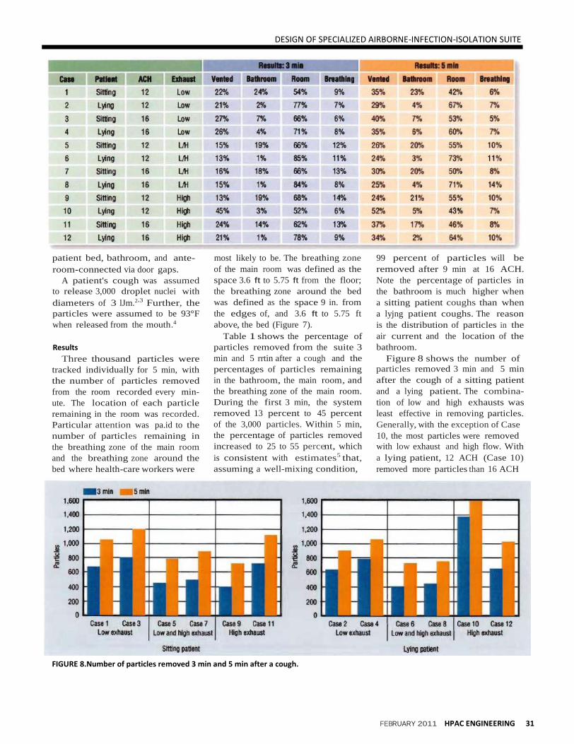
TABLE 1. Case description aad status of 3,000 particles 3 min and 5 min after a cough.
patient bed, bathroom, and ante
room-connected via door gaps.
A patient's cough was assumed
to release 3,000 droplet nuclei with
diameters of 3 lJm.2*3 Further, the
particles were assumed to be 93°F
when released from the mouth.4
Results
Three thousand particles were
tracked individually for 5 min, with
the number of particles removed
from the room recorded every min
ute. The location of each particle
remaining in the room was recorded.
Particular attention was pa.id to the
number of particles remaining in
the breathing zone of the main room
and the breathing zone around the
bed where health-care workers were
most likely to be. The breathing zone
of the main room was defined as the
space 3.6 ft to 5.75 ft from the floor;
the breathing zone around the bed
was defined as the space 9 in. from
the edges of, and 3.6 ft to 5.75 ft
above, the bed (Figure 7).
Table 1 shows the percentage of
particles removed from the suite 3
min and 5 rrtin after a cough and the
percentages of particles remaining
in the bathroom, the main room, and
the breathing zone of the main room.
During the first 3 min, the system
removed 13 percent to 45 percent
of the 3,000 particles. Within 5 min,
the percentage of particles removed
increased to 25 to 55 percent, which
is consistent with estimates5 that,
assuming a well-mixing condition,
99 percent of particles will be
removed after 9 min at 16 ACH.
Note the percentage of particles in
the bathroom is much higher when
a sitting patient coughs than when
a lyjng patient coughs. The reason
is the distribution of particles in the
air current and the location of the
bathroom.
Figure 8 shows the number of
particles removed 3 min and 5 min
after the cough of a sitting patient
and a lying patient. The combina
tion of low and high exhausts was
least effective in removing particles.
Generally, with the exception of Case
10, the most particles were removed
with low exhaust and high flow. With
a lying patient, 12 ACH (Case 10)
removed more particles than 16 ACH
FIGURE 8.Number of particles removed 3 min and 5 min after a cough.

DESIGN OF A SPECIALIZED AIRBORNE-INFECTION-ISOLATION SUITE
32 HPAC ENGINEERING FEBRUARY 2011
(Case 12) with high exhaust. This
can be explained by the flow pattern
above the patient, determined by the
downward forced convection from
the ceiling diffusers above the bed
and the upward flow of the cough
from the mouth of the lying patient.
With greater downward flow (16
ACH, rather than 12 ACH) from the
ceiling diffuser, the upward move
ment of droplets carried by the cough
of a lying patient could be suppressed
and, thus, have difficulty reaching
high exhausts.
For a sitting patient, particles in
the breathing zone generally were
reduced from minutes 3 to 5 (Figure
9). For a lying patient, they sometimes
increased, depending on the ventila
tion system and flow rate. Figure 10
shows the combination of low and
high exhausts resulted in a higher
number of particles in the breathing
zone around the bed, especially in
the cases (6 and 8) of a lying patient.
High exhausts with a high flow rate
(Case 12) did not remove particles
around the bed effectively. Figure 10
indicates fewer particles around the
bed with low exhausts.
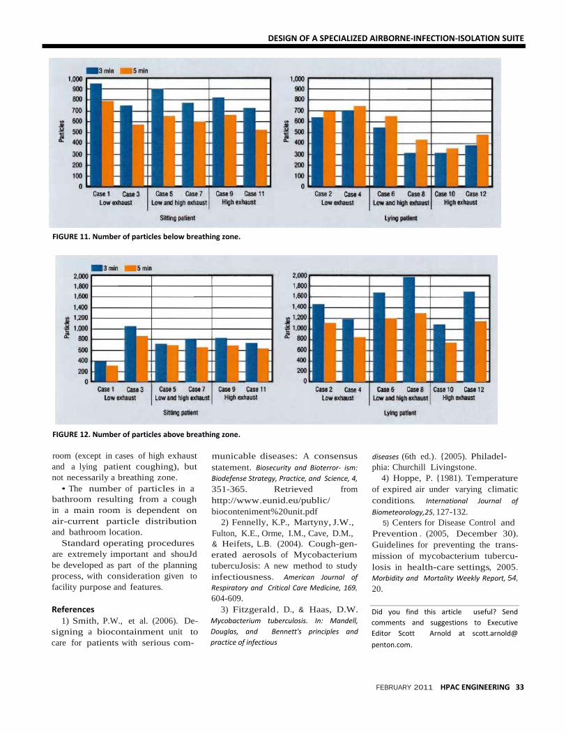
The number of particles below the
breathing zone was higher with low
exhausts than with high exhausts
(Figure 11). High exhausts with high
flow rates (Case 12) did not seem
to remove particles around the bed
effectively. The number of particles
above the breathing zone was higher
with a lying patient regardless of
flow rate and exhaust location (Fig
ure 12). This was attributed primarily
to the initial upward momentum of
the cough jet.
Conclusions
Conclusions that can be drawn
from the study include:
• Low exhaust outperforms other
exhaust locations in terms of particle
removal and number of particles
remaining around a bed.
• Increasing ventilation flow from
12 to 16 ACH generally helps to
remove particles from an isolation
FIGURE 9. Number of particles remaining In breathing zone.
FIGURE 10. Number of particles remaining In breathing zone around bed.
DESIGN OF A SPECIALIZED AIRBORNE-INFECTION-ISOLATION SUITE
FEBRUARY 2011 HPAC ENGINEERING 33
FIGURE 11. Number of particles below breathing zone.
FIGURE 12. Number of particles above breathing zone.
room (except in cases of high exhaust
and a lying patient coughing), but
not necessarily a breathing zone.
• The number of particles in a
bathroom resulting from a cough
in a main room is dependent on
air-current particle distribution
and bathroom location.
Standard operating procedures
are extremely important and shouJd
be developed as part of the planning
process, with consideration given to
facility purpose and features.
References
1) Smith, P.W., et al. (2006). De
signing a biocontainment unit to
care for patients with serious com-
municable diseases: A consensus
statement. Biosecurity and Bioterror ism:
Biodefense Strategy, Practice, and Science, 4,
351-365. Retrieved from
http://www.eunid.eu/public/
bioconteniment%20unit.pdf
2) Fennelly, K.P., Martyny, J.W.,
Fulton, K.E., Orme, I.M., Cave, D.M.,
& Heifets, L.B. (2004). Cough-gen
erated aerosols of Mycobacterium
tubercuJosis: A new method to study
infectiousness. American Journal of
Respiratory and Critical Care Medicine, 169,
604-609.
3) Fitzgerald , D., & Haas, D.W.
Mycobacterium tuberculosis. In: Mandell,
Douglas, and Bennett's principles and
practice of infectious
diseases (6th ed.). {2005). Philadel
phia: Churchill Livingstone.
4) Hoppe, P. {1981). Temperature
of expired air under varying climatic
conditions. International Journal of
Biometeorology,25, 127-132.
5) Centers for Disease Control and
Prevention . (2005, December 30).
Guidelines for preventing the trans
mission of mycobacterium tubercu
losis in health-care settings, 2005.
Morbidity and Mortality Weekly Report, 54,
20.
Did you find this article useful? Send
comments and suggestions to Executive
Editor Scott Arnold at scott.arnold@
penton.com.