design of a microchannel based solar …web.engr.oregonstate.edu/~sva/archive/drost_ijmnst.pdfdesign...
TRANSCRIPT

DESIGN OF A MICROCHANNEL BASED
SOLAR RECEIVER/REACTOR FOR
METHANE-STEAM REFORMING
Drost, K. J., Eilers, B., Apte, S.V.∗, Narayanan, V.†, and Schmitt, J.
School of Mechanical Industrial and Manufacturing EngineeringOregon State University, 204 Rogers Hall, Corvallis, OR 97331
Abstract
This study investigates use of solar thermochemical processing ofclean fuels using biomass products (in particular CH4, H2O). To ad-dress technological feasibility of a microchannel-based solar receiver/reactor,a combined numerical and experimental study of methane-steam re-forming is carried out on a single microchannel with Palladium-depositedchannel walls and heat input to facilitate endothermic heterogeneousreactions producing hydrogen. A simple one-dimensional model solv-ing steady state species mass fraction, energy, and overall conservationof mass equations is developed, calibrated and validated against con-current experimental data [1, 2]. Methane-steam reforming is modeledby three reduced-order reactions occurring on the reactor walls. Theeffects of the total heat input, heat flux profile, and inlet flow rateon production of hydrogen are investigated to assess the effectivenessof the microchannel configuration for production of hydrogen. A cou-pled shape-constrained optimization and Monte-Carlo radiative heattransfer model is developed to design a receiver shape that can yield adesired heat flux distribution on the channel walls for improved yieldof hydrogen.
∗[email protected]†[email protected]
1

1 INTRODUCTION
Solar energy is a promising clean energy source that is of great economicand technological importance. Typically, one of three conversion pathwaysare followed in converting solar energy to usable energy: (a) direct electricalpower through photovoltaics, (b) solarthermal electric power generation, or(c) chemical processing and production of hydrogen or other fuels [3, 4, 5, 6].The present work is motivated from the perspective of trying to addressimportant technological challenges that could enable efficient solar thermo-chemical processing of clean fuels using biomass products (CO2, CH4).
The technological readiness of solar concentrators is relatively high [6, 7];however, there are several areas for advancement in receiver technology thatare needed for improving solar thermochemical processes. Receiver designsthat permit increase in the overall solar to chemical conversion efficiencyare needed. Such designs would necessitate reductions in convective andre-radiative losses from the receiver. The reactor, within which chemicalprocesses take place, needs to permit high completion rate of endothermicreactions. In addition to the receiver and reactor design, process controlschemes that could optimize the production of fuels is needed. Solar re-ceivers based on a volumetric or cavity receiver design are common [8, 9, 10],wherein chemical reactions occur in cylindrical cavities by constraining thereactants and products within the cavity. Chemical reactions in such re-ceivers could be limited by the diffusion time of the non-premixed reactants,low heat transfer rates from the walls to the reactants, and low volumetricabsorption by the reactant gases.
The present work investigates conversion efficiency of biomass-basedgaseous products (in particular CH4) using a microchannel-based reactor,as shown in Figure 1. The concept would involve an array of several mi-crochannel reactors shaped to form the receiver. This design exploits theshort diffusion lengths for reactant gases in microchannels, such that thereaction may occur near stoichiometric conditions (using very less excess re-actant gases), thereby substantially increasing the efficiency of the system.In order to study the technical feasibility of such a design, numerical simula-tions and modeling are used to investigate the strong endothermic reactionsof methane-steam reforming inside a microchannel reactor with Palladiumcatalyst. The simulations are calibrated and validated against concurrentexperiments [1]. Previous work [11] also involved detailed numerical simu-lation using a low-Mach number, unsteady, variable-density Navier-Stokesequations together with species mass-fraction and energy equations solvedfor a three-dimensional microchannel configuration.
2

Figure 1: A microchannel-based biofuel receiver located at the focal pointof a parabolic solar concentrator. The shape of the receiver, which is com-prised of multiple microchannel reactors, is obtained from shape-constrainedoptimization. A simulated large aspect ratio microchannel reactor is usedin the present study.
The primary objective of the present work is to develop a simple one-dimensional model for the thermochemical processes inside the reactor. Themain reason to develop such model is to facilitate several parametric studiesthat can be used to obtain operation range as well as identify conditions forimproved hydrogen production.
The second objective of this work is to develop methodology that willprovide the shape of the receiver necessary to obtain a desired heat fluxdistribution along the microchannel walls. Specifically, knowing the heatflux distribution that produce improved hydrogen production, the goal is todesign the receiver shape that will yield such a distribution. This requiressolution of the radiative heat transfer problem (done using the MONT2Dsoftware [12]) that provides shape factors for a chosen receiver geometry.Next, the radiative solver is coupled with a shape-constrained optimizationprocedure to obtain a receiver shape that will closely provide the desiredheat flux distribution through an iterative approach.
The paper is arranged as follows. A brief description of the experimen-tal setup and the computational model is given first. The mathematicalformulation for heterogeneous surface reaction kinetics as well as the one-dimensional model are summarized next. A brief description of the numer-ical approach is given next. Calibration and validation of the model arepresented followed by parametric studies using the one-dimensional model.
3

Finally, the shape-constraint optimization procedure coupled with a radia-tive heat transfer algorithm is described next.
2 EXPERIMENTAL SETUP
The experimental setup for the present study corresponds to a single large as-pect ratio microchannel considered by Eilers [1] as shown in figure 2a. Heatinput through bottom wall of the microchannel was provided by propaneburners via direct flame impingement, simulating solar energy flux. Thepropane burners could be controlled individually to provide a spatial vari-ations in heat flux along the reactor. The reactor had nine segments ofcontrolled heat input with 0.8 mm gaps between each segment to minimizesubstrate conduction between segments. The first two segments were forpreheating the reactant gases while a porous catalyst bed formed the bot-tom wall in the remaining seven heated segments. The microchannel wasformed by a high temperature gasket shim, compressed between two piecesof stainless steel to form a large aspect ratio channel. The dimensions of themicrochannel were 173.5 mm in length, 19 mm in width, and 700 microme-ters in height. Palladium catalyst was contained on a porous FeCrAlY feltinsert that was 133.5 mm long.
The channel was held together with 30 stainless steel bolts distributedaround the perimeter of the channel in order to distribute the compressiveforce and to minimize the potential for leaks in the system.
(a) (b)
Figure 2: Large-aspect ratio microchannel solar reactor [1, 2]. (a) Schematicof the reactor, (b) expoded view of the reactor.
The catalyst bed was formed of a FeCrAlY sheet that was oxidizedin a furnace at 900C for four hours in an air environment, to create α-alumina and increase the surface area for catalyst deposition. Palladiumnano-particles were synthesized using a modified form of the methods pro-posed in references [13, 14]. The bed was dip coated in the Pd nanoparticlesolution in toluene using a selective technique to enhance the percentage ofcatalyst present at the surface of the catalyst bed. Details of the catalyst
4

preparation and deposition are given in Eilers [1]. Figure 3 shows a sampleSEM image of the catalyst bed after flow shearing test. Particle sizes on theorder of 15 nm were observed but a large degree of agglomeration occurredas can be seen in figure 3. No noticeable reduction in particle density wasobserved after the shear testing, suggesting that particles were adequatelyadhered to the substrate.
Figure 3: SEM image of the catalyst bed after shear testing [1].
Parametric studies of steam-methane ratio, residence time, average reac-tor temperature, and temperature distribution were performed experimen-tally; details are reported in Eilers et al. [1, 2] . Methane conversion wasfound to be strongly dependent on reactor temperature. Linear ramp tem-perature distributions demonstrated about a 46 percent greater hydrogenoutput than isothermal reactions performed at the same average tempera-ture. Results from the experiments were used to calibrate the reaction rateconstant in the 1-D numerical simulations described below.
3 MATHEMATICAL FORMULATION
To perform parametric studies and geometric optimization, a simplified one-dimensional reacting flow model for steady state solution was developed.Accordingly, the plane section of the microchannel (neglecting the inlet andoutlet pipe sections in Figure 2a) was considered with one-dimensional gridalong the flow direction. Using a simple staggered grid and neglecting dif-fusion in the wall-normal direction, the following steady state equations canbe derived:
5
d
dx(ρu) =
d
dx(m′′) = 0 (1)
d
dx(m′′Yi) =
d
dx
(ρDi,m
dYidx
)+ ω′′′i + s′′′i (2)
d
dx(m′′hs) = −dq
′′
dx−
Ns∑i
ω′′′i hofi
+ q′′′surf (3)
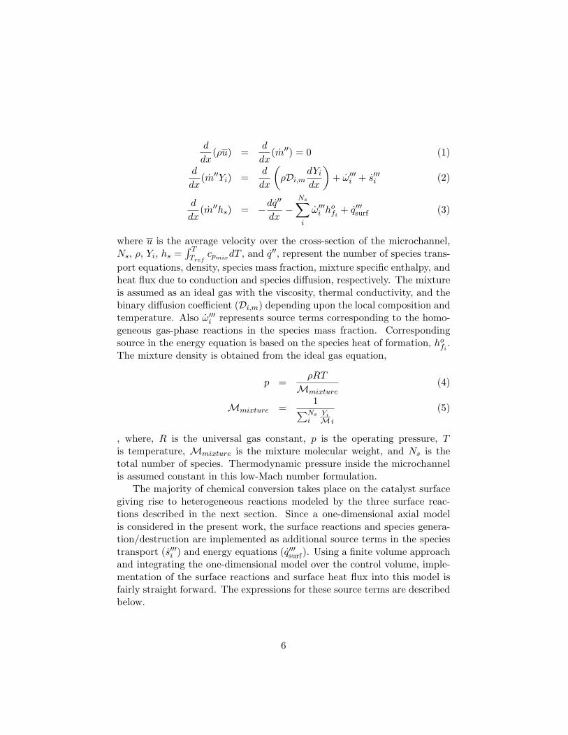
where u is the average velocity over the cross-section of the microchannel,Ns, ρ, Yi, hs =
∫ TTref
cpmixdT , and q′′, represent the number of species trans-port equations, density, species mass fraction, mixture specific enthalpy, andheat flux due to conduction and species diffusion, respectively. The mixtureis assumed as an ideal gas with the viscosity, thermal conductivity, and thebinary diffusion coefficient (Di,m) depending upon the local composition andtemperature. Also ω′′′i represents source terms corresponding to the homo-geneous gas-phase reactions in the species mass fraction. Correspondingsource in the energy equation is based on the species heat of formation, hofi
.The mixture density is obtained from the ideal gas equation,
p =ρRT
Mmixture(4)
Mmixture =1∑Ns
iYiM i
(5)
, where, R is the universal gas constant, p is the operating pressure, Tis temperature, Mmixture is the mixture molecular weight, and Ns is thetotal number of species. Thermodynamic pressure inside the microchannelis assumed constant in this low-Mach number formulation.
The majority of chemical conversion takes place on the catalyst surfacegiving rise to heterogeneous reactions modeled by the three surface reac-tions described in the next section. Since a one-dimensional axial modelis considered in the present work, the surface reactions and species genera-tion/destruction are implemented as additional source terms in the speciestransport (s′′′i ) and energy equations (q′′′surf). Using a finite volume approachand integrating the one-dimensional model over the control volume, imple-mentation of the surface reactions and surface heat flux into this model isfairly straight forward. The expressions for these source terms are describedbelow.
6

The catalytic conversion occurring on the reactor surface can be formu-lated as
−ρDim∂Yi∂n
= s′′iMi; q′′surf = q′′wall +1
Awall
3∑k
rk∆H0R,k, (6)
where s′′i is the rate of chemical species adsorption and desorption at thecatalyst surface, Mi is the molecular weight of species i, q′′wall is the rateof external heat supplied to the wall, ∆H0
R,k is the heat of reaction, rkis the reaction rate of the kth surface reaction, and Awall is the catalystsurface area. The surface adsorption/desorption rates for each ith speciesare obtained as:
s′′i =3∑
k=1
(ν ′ki(rk)− ν ′′ki(rk)
), (7)
where the summation is over the three chemical reactions in the reducedreaction mechanism. The expressions for the reaction rates and the chemicalreaction mechanism are explained in the next section.
The boundary conditions represented by equations 6 are incorporated inthe present one-dimensional finite volume model by adding them as a sourceterm in the species mass and energy equations. The corresponding sourceterms can be obtained as
s′′′i =s′′iMiAcvVcv
(8)
q′′′surf =q′′surfAcvVcv
, (9)
where Vcv and Acv are the volume of the computational cell and surface areaof the catalyst within the computational cell.
The coupled equations for mass, species concentrations, and energy aresolved using an iterative successive over-relaxation scheme. The speciesadvection terms are discretized using a second-order Beam-Warming scheme,properties at the fluxes are evaluated using simple arithmetic averages, anddiffusive fluxes are approximated using a piecewise linear profile assumption(resulting in a symmetric central differencing). Solution is obtained withinonly a few seconds on a laptop.
3.1 Chemical Kinetics for Heterogeneous Reactions
In the microchannel-based solar reactor, chemical reactions can occur in thegaseous phase as well as in a series of reactions on the catalyst surface. Past
7

studies by Deutschmann & Schmidt [15] on oxidation of steam in a tubu-lar model showed that for atmospheric pressures, the gas-phase reactionscontributed negligibly to the oxidation process In the present work, experi-ments are conducted at atmospheric conditions and the gas-phase reactionsare neglected.
It should be noted that the predictive capability of the numerical ap-proach depends on accurate characterization of the surface reactions rates.Detailed chemical kinetics pathways for catalytic surface reactions [16, 15]were used in the modeling of the catalytic reaction on the channel sur-face. Kuznetsov and Koslov [17] used the same three-step reactions, how-ever modeled the reaction rates using the expressions developed by Hou andHughes [18], Xu and Froment [19] based on packed-bed reactor studies.
The catalytic reaction rates are nonlinear relations comprising the reac-tant species concentrations and the local temperature. Modeling of detailedchemical kinetics pathways for catalytic reactions on the surface have beenperformed [16, 15]; however, it can become expensive for wide range ofparametric simulations performed in the present work. A reduced reactionmechanism with the following two endothermic (equations 10,12) and oneexothermic water-gas shift (equation 11) global reactions was used to modelthe chemical conversion. The heats of reaction given for each equation isat 298 K. To calculate the reaction rates, the classical kinetic model wasemployed [20, 21].
CH4 + H2O ⇐⇒ CO + 3H2; ∆H0R = +206 kJ/mol (10)
CO + H2O ⇐⇒ CO2 + H2; ∆H0R = −41 kJ/mol (11)
CH4 + 2H2O ⇐⇒ CO2 + 4H2; ∆H0R = +165 kJ/mol. (12)
There have been previous studies on methane-steam reforming in minichan-nels [22] using similar three-step reduced reaction mechanism with Arrhenius-type reaction rates. As a validation against literature, the numerical ap-proach together with the Arrhenius-type surface reaction rate model [11]were validated against the numerical studies on micrchannel methane-steamreforming performed by Kuznetsov and Koslov [17] using a Nickel catalyst.Their work incorporates the commonly used reaction rate model based onpacked-bed reactor experiments by Hou and Hughes [18].
As mentioned earlier, the catalyst used here was a porous felt with de-posited palladium nanoparticles throughout the felt. In this work, chemi-cal kinetics characteristics for palladium catalyst are taken from Shu et al.[23]. In order to account for this distribution in the numerical model, it
8

was necessary to quantify the surface distribution of the deposited Palla-dium catalyst. However, since the bed was porous, determining the numberand location of active catalyst sites and its effect on reaction rates was notstraightforward. Hence, a reaction-rate correction factor, αs, that modifiesthe pre-exponential factor in the Arrhenius reaction rates (equation 13) wastherefore introduced. Experimental data were used to obtain this reacton-rate correction factor as explained in the results section. Thus, the reactionreaction rates for each chemical reactions was formulated as
rk = kf,kΠNsi=1 [Ci]
ν′ki , (13)
kf,k = αsAkexp(−Ea,kRT
). (14)
where Ci denotes the concentration per unit volume of the ith chemicalspecies in the mixture, kf,k is the specific reaction rate constant for the kth
reaction and ν ′ki, which is dimensionless, is the stoichiometric coefficient ofthe ith chemical species in the kth reaction. The reaction activation energy(Ea,k) and the activation constants Ak for each reaction are obtained fromthe experimental data [18, 19] for Palladium are given in Table 1. Thereaction-rate correction factor αs is obtained from present experimental dataas described later.
Table 1: Pre-exponential factors and activation energies (in kJ/mol) for thethree reactions (equations 10,11,12) for Palladium catalyst.
Catalyst A1 A2 A3 Ea,1 Ea,2 Ea,3Palladium [23] 89.6× 10⁹ 543.5 371.1× 10⁹ 109.4 15.4 209
4 NUMERICAL RESULTS
This section first discusses how the reaction rate correction factor for thenumerical model was obtained by performing calibration studies based onmatching the exit hydrogen concentrations with experimental data [1, 2].The 1D model with appropriate reaction rate correction factor is then usedat other experimental conditions for validation. The validated model is thenused to perform parametric studies varying net heat flux, heat flux distribu-tion, and inlet flow rates to guide in establishing operating parameters formaximal production of hydrogen. Finally, the shape-constrained optimiza-tion procedure and coupling to MONT2D radiative heat solver for obtainingthe shape of the receiver is described.
9

4.1 Quantification of the Reaction-Rate Correction Factor
The quantification of the reaction-rate correction factor using representativeexperimental data is described here. For specified inlet flow rates, steam-to-methane ratio and net heat flux into the reactor, the αs value was variedin the 1-D model to match the bulk exit molar concentration for H2 in theexperiments. The bulk mass fraction (and concentration) at a cross-sectionis obtained as:
Ybulk,H2 =1Acu
∫Ac
uYH2dA. (15)
where u is the average velocity at the cross-section of area Ac. Owing to theheat losses in the experiments, the heat fluxes going into each segment of themicrochannel reactor were not available; rather the total heat input into thereactor was obtained from experiments by doing an overall energy balance.The heat input was assumed uniformly distributed along the microchannelsurface.
Table 2: Calibration studies to obtain reaction-rate correction factors bymatching the exit hydrogen concentrations with experimental data [1].
Case CH4 Flow H2O:CH4 Inlet Inlet Heat Flux ComputedRate g/min Ratio Vel. m/s Temp. ◦C W/m2 αs
1 0.21 2.91 4.91 714 276.3 0.000043252 0.203 2.96 5.09 761 399 0.00006123 0.195 3.06 5.18 798.7 840.7 0.00007484 0.188 3.25 5.38 836.9 1882 0.00010085 0.183 2.87 5.06 902 3908 0.0001463
Table 3: Exit hydrogen concentration compared to experimental resultsfor catalyst C [1] with a constant reaction rate correction factor of αs =6.6× 10⁻⁵.
Case Methane Flow Rate Experiments H2 Predicted H2 Errorg/min Molar Fraction Molar Fraction
1 0.21 0.0788 0.1066 35.28%2 0.203 0.1433 0.1488 3.84%3 0.195 0.219 0.2039 6.89%4 0.188 0.333 0.2831 14.98%5 0.183 0.4803 0.4068 15.30%
10

Table 2 shows the different cases investigated and the corresponding re-action rate correction factors. Ideally, for all cases studied, the correctionfactor would remain constant; however, as seen from the Table 2, some vari-ation in αs value is observed, showing a monotonous decrease with increasein net heat input to the reactor.Averaging the αs values based on the rep-resentative cases shown in Table 2, the mean reaction rate correction factorwas obtained to be 6.6× 10⁻⁵, indicating that the active catalyst sites werea small fraction, consistent with the visual observations in the SEM im-ages. Once this averaged reaction-rate correction factor was determined, itwas kept constant and all the cases were run again to establish the errors innumerically predicted exit hydrogen concentrations compared to experimen-tal measurements. Table 3 indicates the errors in the predicted hydrogenconcentrations compared to the experimentally measured values. Here, thedry concentrations (after removal of the steam for gas chromatography) arecompared showing predictions with reasonable errors. Errors less than 16%were observed for all cases except one with low heat input. These errors arewithin the experimental uncertainty given considerable heat losses observedin the experimental facility [1].
4.2 Parametric Studies Investigating H2 Production
The validated 1D model was used to perform parametric studies varyingthe net heat input to the reactor, the heat flux profile (constant, ramp up,ramp down) along the channel, and the inlet flow rates. Only representativeresults are shown here owing to space constraints.4.2.1 Net Heat Input
The effect of external heat flux on H2 production was investigated as thereaction rates are highly dependent on the local surface temperature. Threeheat flux magnitudes were enforced at mean values of 2, 3 and 4 kW/m2 withuniform distribution along the channel wall. The corresponding amount ofheat input was 394.5, 450.9 and 511.05 W, respectively. The steam-methaneratio was set to 2.7 (case C7) and the flow rate at 0.183g/min. With increasein the amount of heat flux, the H2 production as well as reaction rates at thewall increased. Increased value of heat flux increases the temperature alongthe wall, leading to enhanced H2 production. The average temperatures forthese cases over the reactor were 1145.7, 1170.3 and 1194.3 K, respectively(see figure 4a).
The reaction rates (for R3) plot (figure 4b) showed maximum reactionnear the entrance with continuous decrease in the reaction rate along thechannel. The overall reaction rate values were higher for the higher heat
11

Figure 4: Distributions along the reactor for different uniform heat fluxdistributions: (a) temperature (K), (b) reaction rate (kmol/m2 − s) for re-action 12. Also shown are the corresponding average reactor temperaturesin dashed lines.
flux input. Production of H2 is an endothermic reaction, and this causesthe temperature at the wall to initially decrease. Reactions continue tooccur along the channel wall, however, their rate is decreased. For all cases,the reaction rates went down after the mid-section, and the temperatureincreased owing to thermal heating of the gases. For the cases studied, only26.9% of the initial methane was converted to hydrogen, which is similarto the experimental observation. This may be attributed to small residencetimes compared to the reaction time scales as well as non-uniformity ofreaction sites on the porous surface.
4.2.2 Heat Flux Profile
In practical solar receivers, it is expected that the heat flux profile along themicrochannel wall be non-uniform. In order to explore the effect of heat-flux profile on the non-linear nature of the reaction rates and H2 production,three different heat flux profiles were considered: uniform distribution, rampup, and ramp down wherein the heat flux is varied linearly along the channelwalls. To study the effect of heat flux profile, the average heat input overthe microchannel length was kept fixed and the steam-methane ratio wasset to 2.7 and the flow rate at 0.183g/min. Three different values of the netheat input of 394.5, 450.9 and 511.05 W were studied.
12

Figure 5: Temperature distribution along the reactor for different heat fluxdistributions: (a) linearly descreasing, (b) linearly increasing. Also shownare the corresponding average reactor temperatures.
The temperature distributions along the reactor for different heat fluxdistributions, uniform, linearly decreasing, and linearly increasing are shownin figures 4a, 5a and 5b, respectively. The most interesting case is that of thedecreasing heat flux profile. Figure 5a shows the variation of catalyst tem-perature along the reactor for three different net heat inputs. It is observedthat the mean reactor temperatures were larger for this case compared tothe uniform and decreasing ramp heat flux distributions. For the highestheat input of 533.4 W, the temperature of the reactor actually increasesin the first half of the channel and then decreases. Since endothermic re-actions are occurring in the first half, having larger heat flux (decreasingramp), seems to benefit the reaction rates and net exit hydrogen produc-tion. This suggests that using decreasing ramp for heat flux distribution isimportant and makes use of the input heat for actual methane conversionrather than thermal heating of the product gases as observed in the uniformand increasing heat flux profiles. The hydrogen production (based on exitmolar fraction) for the decreasing heat flux profile was almost 25% highercompared to the increasing ramp function and 11% higher compared to theuniform heat flux profile for the net heat input of 533.4 W.
4.2.3 Inlet Flow Rate
For the baseline case studied (case C7) as well as in the experiments, theinlet flow rate of the methane-steam mixture was 0.183 g/min and the cor-
13

responding mean inlet velocity is 5.06 m/s. This, however, resulted inpartial conversion of the methane to hydrogen. The molar conversion ofa reactant flowing at a fixed velocity in a heterogeneous chemical reactorof fixed length is dictated by diffusion (τd,i = (H/2)2 /Dim) and reaction(τkin = 1/k) time scales, the ratio of which is embodied in the Damkohlernumber (Da = τd,i/τkin) [24]. Here H is the channel height; Dim is the diffu-sion coefficient of species i in mixture m, and k is the reaction rate constant.By measuring the product concentrations, an estimate of the conversion ofthe reactants to products can be obtained. This conversion is affected bydiffusion as well as reaction rates and residence times. In addition, the res-idence time of reactants inside the microchannel is critical and is given byτres = L/u, where L is the length of the microchannel and u is the mean inletvelocity. For the baseline case (C7), the residence time is 0.0263 s, whereasthe diffusion time scale is 0.001038 s. This resulted in methane conversionof only 26.9% based on the inlet and exit molar fractions for the highestheat input.
Figure 6: Mole fraction distributions along the reactor for linearly decreasingheat flux distribution with an inlet flow rate of 0.026 g/min: (a) CH4 and(b) H2
A series of simulations were performed varying the inlet flow rates tillcomplete conversion of methane to hydrogen was obtained, keeping all otherparameters the same. The inlet mean flow velocity for complete conversionwas found to be 0.721 m/s corresponding to a flow rate of 0.026 g/min (fig-ures 6a,b). The corresponding residence time is 0.185 s. With increasedresidence times, it was observed that the reaction rates for the endothermic
14

reaction 11 steadily increased from the inlet section till the outlet section,resulting in complete conversion. This indicates that for complete conver-sion, a longer channel (almost five times) would be necessary at the samebaseline flow rate used in experiments.
4.3 Receiver Shape Optimization
The hydrogen produced by a solar receiver will depend upon the radiativeheat transfer occurring within the receiver that results in a heat flux profilealong the receiver walls and the reactions occurring within the microchan-nels. The shape of the receiver dictates the incident radiative heat fluxprofile. Ideally, shape optimization of the receiver would entail specifyingan initial receiver shape, with Monte-Carlo based radiative heat transfer andray tracing employed to determine a heat flux profile along the length of thereceiver. This heat flux profile would then be employed in a 1-D steadyreduced-reaction model to determine the steady state hydrogen output forthe receiver shape. In absence of the fully coupled receiver shape-reactormodeling approach to predict hydrogen output, receiver shape optimizationis limited in this work to matching a desired heat-flux profile along thelength of the receiver. To illustrate the methodology and present approach,a linear heat flux variation along the length of the receiver was used. Asshown previously, a decreasing ramp function for the heat flux profile alongthe microchannel provides the most hydrogen output. As such, the opti-mization problem examined in this paper reduces to identifying a receivershape that explicitly matches a prescribed linearly varying heat flux profilealong the length of the receiver wall.
In this work, the shape of the solar receiver is assumed symmetric aboutan axis of revolution, such that the receiver can be designed in two dimen-sions (r,z). Reactants are assumed to enter at the cavity opening side ofthe receiver and flow along the length of the receiver within microchannelreactors and exit at the rear end of the receiver. The rear of the receiveris assumed to consist of a flat bottom of radius r0, located on the r-axis,and the receiver extends for a height h along the z-axis. As stated, theoptimization search space contains the set of all possible receiver shapes. Toreformulate the maximization problem in a finite, lower-dimensional formthat can be numerically solved by sequential quadratic programming (SQP)algorithms, the receiver shape is instead represented by a set of coordinates(ri,zi). Chebyshev polynomials are utilized to fit a receiver shape throughthese points, where ri represent the radial position of the Chebyshev inter-polation points. In this manner, the optimization problem is therefore trans-
15

−1 0 1 2
0
0.5
1
1.5
2
2.5
3
r / r0
z / r
0
Interpolated Surface
Chebyshev Points
Symmetry Axis
Figure 7: Example of axisymmetric receiver shape. The symbols are theChebyshev points that define the shape. 20 discrete surfaces are fit to theChebyshev polynomial to form the enclosure sent to MONT2D.
formed into one in which the optimization routine must determine the coor-dinates ri at each grid point such that a quadratic cost function J = zTQzis minimized. The minimization of the cost function is performed subject todesign constraints on the radial locations of the interpolation points. In thecost function J , the vector z represents the difference between the heat fluxproduced by the receiver shape and the desired heat flux profile at prescribedlocations along the receiver length and Q represents a weighting matrix.
Although finite in number, the coordinates (ri, zi) produce a continuousreceiver shape via the Chebyshev polynomial representation. The resultingconstrained, finite dimensional, nonlinear optimization problem is solvedin MATLAB using SNOPT [25], a particularly robust implementation ofa SQP algorithm. Provided with an initial guess of the receiver shape, asspecified by the radial locations of the Chebyshev interpolation points, aMATLAB function discretizes the receiver shape via piecewise linear poly-nomials for use in MONT2D, a freely available Monte-Carlo based radiativeheat transfer and ray tracing program [12]. These studies use seven Cheby-shev points to create the interpolated polynomial which is discretized into20 surfaces for MONT2D. Figure 7 shows an example of the Chebyshev sur-face interpolation and surface discretization for an arbitrary receiver shape.The MATLAB function creates an input file with the coordinates of thediscretized receiver shape along with material properties and solver optionsbefore starting the MONT2D solver.
MONT2D interprets the radial position of the last Chebyshev point asthe radius of the aperture through which solar energy enters the receiver.
16

MONT2D requires a surface to be specified at the aperture so that all of thesurfaces form an enclosure. At the aperture surface, MONT2D emits andtracks photons, through possible reflections, until absorption. The apertureis assumed to be a diffuse emitter and a blackbody absorber as all the pho-tons that hit the aperture surface would be lost to the surroundings. Thereceiver walls are assumed to be a stainless steel that is a perfectly diffusereflector and absorbs 50% of incoming photons independent of incident an-gle. Additionally, all surface properties are assumed to be independent ofradiation wavelength. The exchange fraction is defined by Fi = Ni/Ntotal,where Fi is the exchange fraction between the aperture surface and surfacei, Ni is the total number of photons absorbed by surface i, and Ntotal is thetotal number of emitted photons from the aperture surface. The MATLABcode reads the output file from MONT2D and proceeds to calculate a heatflux profile. The total heat flux is specified for the aperture and thus thetotal radiative energy entering the enclosure is known. The incident radia-tion for a given surface is given by qi = qaperture ∗ Aaperture ∗ Fi/Ai, whereqi is the energy flux absorbed by surface i, qaperture is the energy flux en-tering the aperture, Aaperture is the axisymmetric area of the aperture, Fi isthe exchange fraction between the aperture surface and surface i, and Ai isthe axisymmetric area of surface i. The qi values form a discrete heat fluxprofile along the length of receiver wall accounting for the length changesof the receiver based on the wall curvature. This profile is compared to thetarget linear profile for each surface and the error vector, z, is calculated asthe absolute value of the difference between the calculated heat flux and thetarget heat flux normalized by the number of surfaces. For these studies theweighting matrix Q was the identity matrix.
SNOPT was subsequently responsible for determining new values forthe radial locations of the Chebyshev interpolation points and this processwas repeated until the cost function, subject to the bounds on the valuesfor the interpolation points, was minimized. The efficacy of this strategyis illustrated through its ability to identify a receiver shape that produceda ramp-down heat flux profile that varied linearly along the length of thereceiver. The optimized shape is shown in figure 8. The heat flux profile isindependent of length scale and scales linearly with the aperture heat fluxfor a constant aspect ratio.
These results show that it is possible to closely match a linear heat fluxprofile with a combination of SNOPT and MONT2D. The average and max-imum error between the calculated and target heat flux profiles are 1.2% and11.9% respectively. While this final error is small, there are two factors thatreduce the robustness of this method. Appropriate values require an itera-
17

−1 0 1 2
0
0.5
1
1.5
2
2.5
3
r / r0
z / r
0
Interpolated Surface
Chebyshev Points
Symmetry Axis
Figure 8: Receiver shape obtained from the optimization procedure for aspecified ramp-down heat flux profile. Here the reactants are flowing fromz/r0 = 0 to z/r0 = 3.
tive approach by the user. Additionally, the precision of Monte-Carlo resultssomewhat interferes with the SNOPT optimization routine. This routineworks best with smooth or nearly-smooth functions. By their stochasticnature, Monte Carlo methods do not produce smooth results. Using thesame inputs, exec6uting MONT2D twice will produce slightly different an-swers. This difference reduces robustness especially when SNOPT estimatesderivatives of the objective function, J , using finite difference approxima-tions. To mitigate this effect, the number of photons emitted by MONT2Dwas increased to a value on the order of 108. This significantly increasedthe computational expense of evaluating J , but was necessary for SNOPTto find an acceptable solution.
5 CONCLUSION
The design of a microchannel reactor geometry for methane-steam reform-ing was investigated using a simple steady-state one-dimensional model .Methane-steam reforming was modeled by three reduced-order reactions oc-curring on the reactor walls, two of which were endothermic reactions andan exothermic water-gas shift reaction. The surface chemical reactions weremodeled source terms in the energy and species mass fraction equations,with Arrhenius-type reaction rate models for Palladium-deposited catalyst.
First the numerical model was applied to predict hydrogen production in
18

a microchannel setup based on the experimental setup of Eilers [1] to showgood predictive capability. In order to account for the non-uniformity andintermittency in active sites, a simple model modifying the reaction rate con-stant through a single constant factor was investigated. The reaction-ratecorrection factor was determined by matching the exit hydrogen produc-tion against the experimental data for one particular flow rate. Using thisreaction-rate constant, simulations were performed at different flow ratesand hydrogen production was compared with the experimental data to showreasonable agreement. This validation shows that use of an experimentallycalibrated reaction-rate factor can be used to perform parametric studiesand prediction of hydrogen production in microchannel reactors. Paramet-ric studies were then performed by varying the net heat input, heat fluxprofile along the microchannel, and the inlet flow rate to study their effecton the methane conversion.For a given flow rate and heat input, a decreas-ing ramp function for the heat flux along the microchannel yielded increasedhydrogen production. By controlling the inlet flow rates that alter the res-idence time compared to the reaction time scales, complete conversion ofCH4 to H2 was feasible.
Finally, a shape-constrained optimization procedure using the SNOPTalgorithm coupled with the radiative heat transfer module MONT2D [12]was developed to design the receiver shape that provides a desired heat fluxprofile along the microchannel length. This optimization process can beused to design receiver shapes for optimal hydrogen production.
Acknowledgement
This work was funded partly by the Oregon Best Solar energy initiativeand the Oregon Nano and Microtechnology Institute (ONAMI). We alsothank Prof. Murty Kanury of OSU for several useful discussions related tocombustion and chemical kinetics modeling.
References
[1] Eilers, B., 2010, “Microchannel steam-methane reforming under con-stant and variable surface temperature distributions,” M.S. Thesis, Ore-gon State University.
[2] Eiler, B., Narayanan, V., Apte, S., and Schmitt, J., 2011, “Steam-methabe reforming in a microchannel under constant and variablesurface temperature profiles,” AJTEC2011-44390, Proceedings of the
19

ASME/JSME 2011 8th Thermal Engineering Joint Conference, Hon-olulu, Hawaii, USA.
[3] Tamme, R., Buck, R., Epstein, M., Fisher, U., and Sugarmen, C., 2001,“Solar upgrading of fuels for generation of electricity,” Journal of SolarEnergy Engineering, 123, p. 160.
[4] Moller, S., Kaucic, D., and Sattler, C., 2006, “Hydrogen productionby solar reforming of natural gas: a comparison study of two possi-ble process configurations,” Journal of Solar Energy Engineering, 128,p. 16.
[5] Kodama, T., Moriyama, T., Shimoyama, T., Gokon, N., Andou, H.,and Satou, N., 2006, “Ru/ Ni–Mg–O catalyzed SiC-foam absorber forsolar reforming receiver-reactor,” Journal of Solar Energy Engineering,128, p. 318.
[6] Wegeng, R., TeGrotenhuis, W., and Mankins, J., 2007, “Solar ther-mochemical production of fuels,” AIAA, 2007-4709, 5th InternationalEnergy Conversion Engineering Conference and Exhibit.
[7] Wegeng, R. and Mankins, J., 2009, “Space power systems: Producingtransportation (and other chemical) fuels as an alternative to electricitygeneration,” Acta Astronautica, 65(9-10), pp. 1261–1271.
[8] Steinfeld, A., 2005, “Solar thermochemical production of hydrogen—-areview,” Solar Energy, 78(5), pp. 603–615.
[9] Roger, M., Pfander, M., and Buck, R., 2006, “Multipleair-jet window cooling for high-temperature pressurized volu-metric receivers: Testing, evaluation, and modeling,” Jour-nal of Solar Energy Engineering, 128(3), pp. 265–274, URLhttp://link.aip.org/link/?SLE/128/265/1.
[10] Kraupl, S. and Steinfeld, A., 2001, “Pulsed gas feeding for stoichiomet-ric operation of a gas-solid vortex flow solar chemical reactor,” Journalof Solar Energy Engineering, 123, p. 133.
[11] Drost, K., Eiler, B., Peterson, D., Apte, S., Narayanan, V., andSchmitt, J., 2011, “Detailed numerical modeling of a microchannel re-actor for methane-steam reforming,” AJTEC2011-44664, Proceedingsof the ASME/JSME 2011 8th Thermal Engineering Joint Conference,Honolulu, Hawaii, USA.
20

[12] Maltby, J., Zeeb, C., Dolaghan, J., and Burns, P., 1994, “Users manualfor MONT2D-version 2.6 and MONT3D-version 2.3,” Department ofMechanical Engineering, Colorado State University, Fort Collins, CO.
[13] Valmikanathan, O., Ostroverkhova, O., Mulla, I., Vijayamohanan, K.,and Atre, S., 2008, “The effect of synthesis procedure on the structureand properties of palladium/polycarbonate nanocomposites,” Polymer,49(16), pp. 3413–3418.
[14] Brust, M., Bethell, D., Kiely, C., and Schiffrin, D., 1998, “Self-assembled gold nanoparticle thin films with nonmetallic optical andelectronic properties,” Langmuir, 14(19), pp. 5425–5429.
[15] Deutschmann, O. and Schmidt, L., 1998, “Modeling the partial oxi-dation of methane in a short-contact-time reactor,” AIChE Journal,44(11), pp. 2465–2477.
[16] Stutz, M. J. and Poulikakos, D., 2005, “Effects of microreactor wallheat conduction on the reforming process of methane,” Chemical En-gineering Science, 60(24), pp. 6983 – 6997.
[17] Kuznetsov, V. and Kozlov, S., 2008, “Modeling of methane steam re-forming in a microchannel with a heat flow distributed in length,” Jour-nal of Engineering Thermophysics, 17(1), pp. 53–59.
[18] Hou, K. and Hughes, R., 2001, “The kinetics of methane steam re-forming over a Ni/α-Al2O catalyst,” Chemical Engineering Journal,82(1-3), pp. 311–328.
[19] Xu, J. and Froment, G., 1989, “Methane steam reforming, methanationand water-gas shift: I. Intrinsic kinetics,” AIChE Journal, 35(1), pp.88–96.
[20] Kenneth, K., 2005, “Principles of combustion,” John Wiley’s sons, Ine,Hoboken, New Jersey.
[21] Turns, S., 1995, “An introduction to combustion: Concepts and appli-cations(Book),” New York: McGraw-Hill, Inc, 1995.
[22] Wang, Y., Yoshiba, F., Kawase, M., and Watanabe, T., 2009, “Perfor-mance and effective kinetic models of methane steam reforming overNi/YSZ anode of planar SOFC,” International Journal of HydrogenEnergy, 34(9), pp. 3885–3893.
21

[23] Shu, J., Grandjean, B., and Kaliaguine, S., 1994, “Methane Steam Re-forming in Asymmetric Pd-Ag and Pd-Ag/Porous SS Membrane Reac-tors,” Applied Catalysis A: General, 119(2), pp. 305–325.
[24] Kanury, A., 1984, “Introduction to combustion phenomena,” Gordonand Breach Science Publishers, New York, Fourth printing.
[25] Gill, P., Murray, W., and Saunders, M., 2005, “SNOPT: An SQP algo-rithm for large-scale constrained optimization,” SIAM Review, 47(1),pp. 99–131.
22