design of a low noise amplifier for a satellite …
TRANSCRIPT

DESIGN OF A LOW NOISE AMPLIFIER FOR A
SATELLITE RECEIVER AT KA BAND FOR TROPICAL
REGION
BY
KAZI SHIHAN MIRZA
A dissertation submitted in fulfilment of the requirement for
the degree of Master of Science (Communication
Engineering)
Kulliyyah of Engineering
International Islamic University Malaysia
December 2019
ii
ABSTRACT
In satellite communication systems, Ku and C bands have become highly congested
and future applications need to move towards Ka band. Satellite downlink
communication for Ka band at 20GHz in the tropical region is challenging because of
high precipitation rate and susceptible to high rain attenuation. That is why there is a
need to study rain fade and BER performance of RF receiver at Ka band for tropical
region. Low Noise Amplifier is the most crucial part of a RF receiver as it is located
immediately after the antenna in the receiver. An LNA with a quite high gain and low
noise figure can mitigate the noise contribution role of next stages of RF receiver and
thus enhancing the receiver BER performance. In this project, a six staged cascaded
Low Noise Amplifier with a high gain of 35.236 dB and a noise figure of 2.242 dB
has been designed. Rain fades using ITU-R model are calculated for 99.9%, 99.99%
and 99.999% availabilities for vertical, horizontal and circular polarization. The rain
fades at 99.99% availability for vertical, horizontal and circular polarizations are
found to be 34.741 dB, 40.843 dB and 37.635 dB respectively. Integrating the
designed LNA into a RF satellite earth station receiver, the BER performance of the
receiver is estimated for different availability rates for different levels of PSK
modulation schemes and different polarizations. The bandwidth of 20 MHz for DBS-
TV has been used. The result shows that BER performances are unacceptable at
99.9%, 99.99% and 99.999% availabilities for all three types of polarizations and all
levels of PSK modulation schemes. However performances are found acceptable at
varying availabilities from 99.1% to 99.7% for BPSK and QPSK modulation with
different polarizations. From 8-PSK to higher level of PSK modulation schemes, BER
is inappropriate for 99.1% or higher availabilities for all three polarizations. The
minimum fade margins for BPSK, QPSK, 8-PSK, 16-PSK, 32-PSK are 2.88 dB,
5.89dB, 11.22 dB, 17.07 dB, 23.08 dB respectively by considering 8.5 dB as threshold
for DBS-TV.
iii
خلاصة البحثABSTRACT IN ARABIC
التوجهجدا وتحتاج تطبيقات المستقبل الى ةمزدحم Cو Ku احزمة الفضائية، أصبحت تالاتصالاانظمة في في المناطق الاستوائية غيغا هرتز 20حدود في Kaزمة الهابطة لح ت الفضائية الاتصالاان . Ka لاستخدام حزمة
هناكف ا. ولهذيعتبر تحديا وذلك بسبب معدل الهطول العالي للامطاروبالتالي تتعرض الاشارة للتخفيف بسبب المطران في المنطقة الاستوائية. Kaحزمة في RFلمستقبل لمتلقي او BER داءوإ تلاشي وتخفيف اثر المطرحاجة لدراسة
وائي في مستقبل اله خلف قع مباشرةيوهو RF لجزء المهم والحاسم في مستقبل هو أالمنخفض مضخم الضوضاء RF . الضجيج مساهمة من اثر مع مكسب عالي وضجيج منخفض يستطيع أن يخفف المنخفض مضخم الضوضاءان
ضوضاءالمضخم ميمصتم ت. في هذه الأطروحة، BERأداء يعزز ويسحن من وذلك RFلاحقة لمستقبل راحللم. dB 2.424ورقم ضوضاء مساوي ل dB 35.236ل يمساو عالي بمكسب المخفض على ست مراحل متتالية
من % 99.999%, 99.99%, 99.9 للنسب ITU-R وتلاشي تاثير المطرباستخدام نموذج تخفيف تم حساب% للاستقطابات العمودي، 99.99 لمتاح فيا مودية والدائرية.ان تلاشي تاثير المطرية والعللاستقطابات الأفقيالمتاح
تم دمج وتكامل مضخم على التوالي. dB 37.635و dB ،dB 40.843 34.741 كان ائريالأفقي والد للمستقبل تم تقيرهما لمتاحيات BER واداء المحطة الفضائية الارضية RF الضوضاء المنخفض المصمم في مستقبل
20 عرض نطاق تم استخدام .للاستقطاب درجات مختلفة PSK لمعدلات مخطط التعديلواستقطابات مختلفة %, 99.9غير مقبول في متاحيات كان BER ان النتائج دلت على ان اداء . DBS-TVل ميغاهيرتز لقد وجد بان اداءمع ذلك و . PSK مخطط التعديللكل مستويات ستقطابات و لا% لكل ا%99.999, 99.99BER التعديل % لمخطط 99.7 وبين% 99.1 تتراوح بينمتفاوتة اتمقبولة في متاحيكان مقبولاBPSK
BER كان اداءعالي، تعديلمخطط الى PSK-8تعديل مخطط من .الثلاثة الاستقطابات انواعلكل QPSKو التلاشي. الحد الأدنى من هوامش ت الثلاثة ستقطابالاا انواع لكل او اعلى %99.1 لقيمة متاحية غير مقبول لمتاحية
، dB ،5.89 dB 11.22 dB 2.88هو PSK-32و BPSK ،QPSK ،8-PSK ،16-PSKل17.07 dB ،23.08 dB 8.5على التوالي باعتبار dB ل ة او بدايةعتبDBS-TV .

iv
APPROVAL PAGE
I certify that I have supervised and read this study and that in my opinion, it conforms
to acceptable standards of scholarly presentation and is fully adequate, in scope and
quality, as a dissertation for the degree of Master of Science (Communication
Engineering).
Md. Rafiqul Islam
Supervisor
Khaizuran Bin Abdullah
Co-Supervisor
I certify that I have read this study and that in my opinion it conforms to acceptable
standards of scholarly presentation and is fully adequate, in scope and quality, as a
dissertation for the degree of Master of Science (Communication Engineering).
Sheroz Khan
Internal Examiner
Ahmad Zamani Bin Jusoh
Internal Examiner
This dissertation was submitted to the Department of Electrical and Computer
Engineering and is accepted as a fulfilment of the requirement for the degree of
Master of Science (Communication Engineering).
Mohamed Hadi Habaebi
Head, Department of Electrical
and Computer Engineering
This dissertation was submitted to the Kulliyyah of Engineering and is accepted as a
fulfilment of the requirement for the degree of Master of Science (Communication
Engineering).
Ahmed Faris Ismail
Dean, Kulliyyah of Engineering

v
DECLARATION
I hereby declare that this dissertation is the result of my own investigations, except
where otherwise stated. I also declare that it has not been previously or concurrently
submitted as a whole for any other degrees at IIUM or other institutions.
Kazi Shihan Mirza
Signature ........................................................... Date .........................................

vi
COPYRIGHT PAGE
INTERNATIONAL ISLAMIC UNIVERSITY MALAYSIA
DECLARATION OF COPYRIGHT AND AFFIRMATION OF
FAIR USE OF UNPUBLISHED RESEARCH
DESIGN OF A LOW NOISE AMPLIFIER FOR A SATELLITE
RECEIVER AT KA BAND FOR TROPICAL REGION
I declare that the copyright holders of this dissertation are jointly owned by the student
and IIUM.
Copyright © 2019Kazi Shihan Mirzaand International Islamic University Malaysia. All rights reserved.
No part of this unpublished research may be reproduced, stored in a retrieval system,
or transmitted, in any form or by any means, electronic, mechanical, photocopying,
recording or otherwise without prior written permission of the copyright holder
except as provided below
1. Any material contained in or derived from this unpublished research may
be used by others in their writing with due acknowledgement.
2. IIUM or its library will have the right to make and transmit copies (print
or electronic) for institutional and academic purposes.
3. The IIUM library will have the right to make, store in a retrieved system
and supply copies of this unpublished research if requested by other
universities and research libraries.
By signing this form, I acknowledged that I have read and understand theIIUM
Intellectual Property Right and Commercialization policy.
Affirmed by Kazi Shihan Mirza
……..…………………….. ………………………..
Signature Date

vii
ACKNOWLEDGEMENTS
All praises and glory be to Allah swt without whose help and mercy it would not be
possible for me to finish this research. Peace and blessing be upon His last messenger
and prophet Muhammad (pbuh).
I am immensely grateful to my supervisor, Prof. Dr. MD Rafiqul Islam who
constantly guided and motivated me throughout this research. He was kind enough to
give me consultation whenever I sought. Because of his brilliant apprehension of the
aim and goal of this research, he was able to provide me with insights and suggestions
which enabled me to finish this research. I am also grateful to my co-supervisor
Assoc. Prof. Dr. Khaizuran Bin Abdullah whose comments also contributed to the
accomplishment of this research.
Last but not least, I am grateful to my parents whose prayer probably is the
thing that kept me going till the last of this research and who had to bear the hardship
of my being away from them for so long for the purpose of this research.
viii
TABLE OF CONTENTS
Abstract ............................................................................................................... ii Abstract in Arabic ................................................................................................ iii
Approval Page ..................................................................................................... iv Declaration .......................................................................................................... v
Acknowledgements ............................................................................................. vii Table of Contents ................................................................................................ viii
List of Tables ....................................................................................................... x List of Figures ..................................................................................................... xi
List of Abbreviations ........................................................................................... xiv List of Symbols ................................................................................................... xv
CHAPTER ONE: INTRODUCTION ............................................................... 1
1.1 Background of The Study ................................................................... 1 1.2 Problem Statement and Its Significance .............................................. 2
1.3 Research Objectives ............................................................................ 4 1.4 Research Methodology........................................................................ 4
1.5 Research Scope ................................................................................... 6 1.6 Thesis Organizations ........................................................................... 6
CHAPTER TWO: LITERATURE REVIEW .................................................. 7
2.1 Introduction ........................................................................................ 7 2.2 Satellite Receiver ................................................................................ 7
2.3 Low Noise Amplifier .......................................................................... 8 2.3.1 0.18μm pHEMT Based Four Stage Monolithic LNA .................. 9
2.3.2 0.15 µm InGaAs pHEMT Based Two Stage LNA ...................... 10 2.3.3 0.15 Μm GaAs pHEMT Based Two Stage LNA With
Coplanar Waveguide Structure .................................................. 12 2.3.4 TSMC 0.18μm CMOS Based Two Stage LNA .......................... 14
2.3.5 TSMC 0.18μm CMOS Based Two Stage LNA .......................... 15 2.3.6 0.13μm Metamorphic HEMT Based Four Stage LNA ................ 17
2.3.7 InAlN/GaN MOS-HEMT Based Three Stage LNA .................... 19 2.3.8 0.1μm pHEMT Based Two Stage LNA ...................................... 21
2.3.9 Ne3520 N-Channel HJ-FET Based Two Staged LNA ................ 23 2.4 Propagation Impairment ...................................................................... 24
2.5 Rain Attenuation ................................................................................. 27 2.6 Summary ............................................................................................ 31
CHAPTER THREE: LOW NOISE AMPLIFIER DESIGN............................ 32
3.1 Introduction ........................................................................................ 32 3.2 LNA Parameters ................................................................................. 32
3.2.1 Scattering Parameters ................................................................ 33 3.2.2 Stability ..................................................................................... 35
3.2.3 Noise Figure .............................................................................. 36 3.2.4 Gain ........................................................................................... 37
3.2.5 Impedance Matching.................................................................. 38
ix
3.3 Tools & Equipment ............................................................................. 39
3.4 LNA Design........................................................................................ 40 3.4.1 Transistor Selection ................................................................... 40
3.4.2 Substrate Selection..................................................................... 41 3.4.3 Bias ........................................................................................... 41
3.4.4 Simulation Of The Basic Electrical Model With Bias ................. 43 3.4.5 RF Choke Design....................................................................... 45
3.4.6 Transistor With Rf Choke .......................................................... 47 3.4.7 Impedance Matching.................................................................. 48
3.4.8 Final Design .............................................................................. 52 3.5 Benchmark .......................................................................................... 55
3.6 Summary ............................................................................................ 56
CHAPTER FOUR: ESTIMATING RAIN FADE AND PERFORMANCE
EVALUATION .................................................................................................. 58
4.1 Introduction ........................................................................................ 58 4.2 Satellite And Earth Station Specification ............................................. 58
4.3 Estimating Rain Attenuation ............................................................... 59 4.3.1 Rain Attenuation for LP-V ......................................................... 60
4.3.2 Rain Attenuation for LP-H ......................................................... 62 4.3.3 Rain Attenuation for CP ............................................................. 64
4.4 System Noise Temperature ................................................................. 66 4.5 Carrier to Noise Ratio ......................................................................... 68
4.6 Performance Evaluation ...................................................................... 73 4.6.1 Bit Error Rate ............................................................................ 73
4.6.2 Psk (Phase Shift Keying) ........................................................... 73 4.6.3 Ber Calculation .......................................................................... 73
4.7 Estimating Fade Margin ...................................................................... 77 4.8 Summary ............................................................................................ 79
CHAPTER FIVE: CONCLUSION AND FUTURE WORK ........................... 81
5.1 Conclusions ........................................................................................ 81 5.2 Future Work........................................................................................ 83
REFERENCES ................................................................................................. 84
APPENDIX ....................................................................................................... 86
x
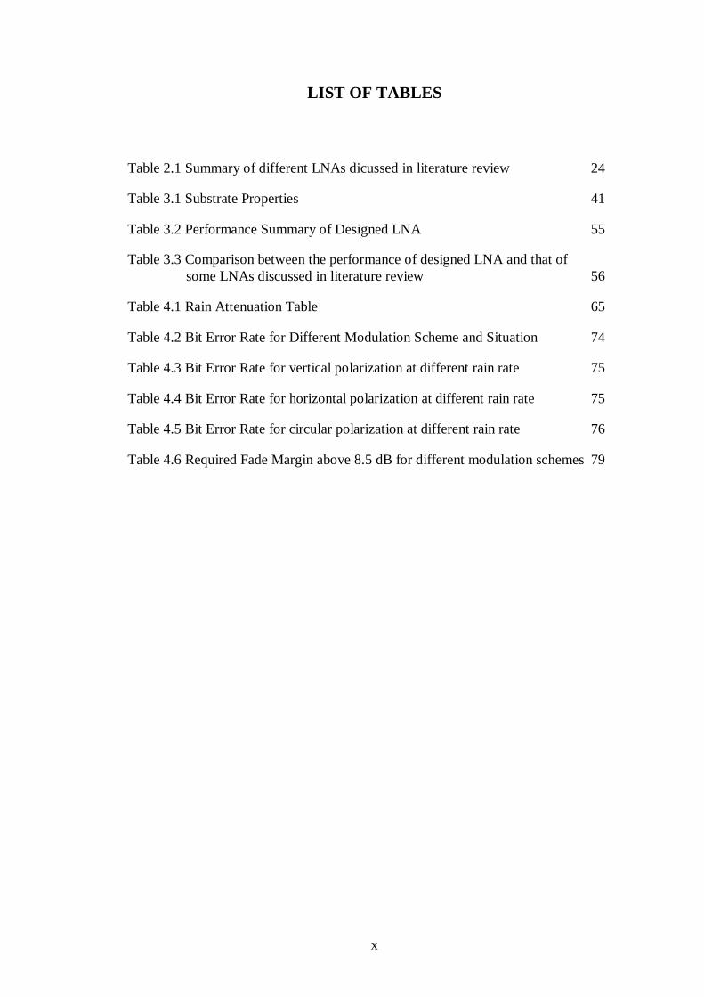
LIST OF TABLES
Table 2.1 Summary of different LNAs dicussed in literature review 24
Table 3.1 Substrate Properties 41
Table 3.2 Performance Summary of Designed LNA 55
Table 3.3 Comparison between the performance of designed LNA and that of
some LNAs discussed in literature review 56
Table 4.1 Rain Attenuation Table 65
Table 4.2 Bit Error Rate for Different Modulation Scheme and Situation 74
Table 4.3 Bit Error Rate for vertical polarization at different rain rate 75
Table 4.4 Bit Error Rate for horizontal polarization at different rain rate 75
Table 4.5 Bit Error Rate for circular polarization at different rain rate 76
Table 4.6 Required Fade Margin above 8.5 dB for different modulation schemes 79
xi
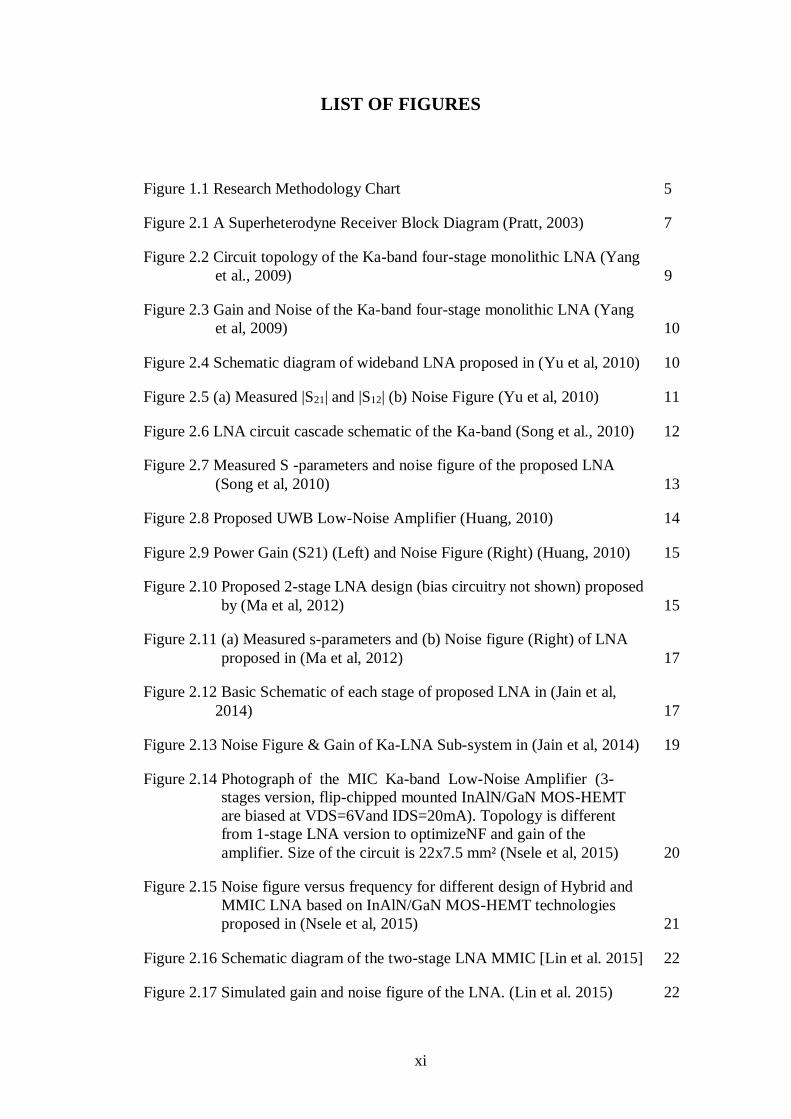
LIST OF FIGURES
Figure 1.1 Research Methodology Chart 5
Figure 2.1 A Superheterodyne Receiver Block Diagram (Pratt, 2003) 7
Figure 2.2 Circuit topology of the Ka-band four-stage monolithic LNA (Yang
et al., 2009) 9
Figure 2.3 Gain and Noise of the Ka-band four-stage monolithic LNA (Yang
et al, 2009) 10
Figure 2.4 Schematic diagram of wideband LNA proposed in (Yu et al, 2010) 10
Figure 2.5 (a) Measured |S21| and |S12| (b) Noise Figure (Yu et al, 2010) 11
Figure 2.6 LNA circuit cascade schematic of the Ka-band (Song et al., 2010) 12
Figure 2.7 Measured S -parameters and noise figure of the proposed LNA
(Song et al, 2010) 13
Figure 2.8 Proposed UWB Low-Noise Amplifier (Huang, 2010) 14
Figure 2.9 Power Gain (S21) (Left) and Noise Figure (Right) (Huang, 2010) 15
Figure 2.10 Proposed 2-stage LNA design (bias circuitry not shown) proposed
by (Ma et al, 2012) 15
Figure 2.11 (a) Measured s-parameters and (b) Noise figure (Right) of LNA
proposed in (Ma et al, 2012) 17
Figure 2.12 Basic Schematic of each stage of proposed LNA in (Jain et al,
2014) 17
Figure 2.13 Noise Figure & Gain of Ka-LNA Sub-system in (Jain et al, 2014) 19
Figure 2.14 Photograph of the MIC Ka-band Low-Noise Amplifier (3-
stages version, flip-chipped mounted InAlN/GaN MOS-HEMT
are biased at VDS=6Vand IDS=20mA). Topology is different
from 1-stage LNA version to optimizeNF and gain of the
amplifier. Size of the circuit is 22x7.5 mm² (Nsele et al, 2015) 20
Figure 2.15 Noise figure versus frequency for different design of Hybrid and
MMIC LNA based on InAlN/GaN MOS-HEMT technologies
proposed in (Nsele et al, 2015) 21
Figure 2.16 Schematic diagram of the two-stage LNA MMIC [Lin et al. 2015] 22
Figure 2.17 Simulated gain and noise figure of the LNA. (Lin et al. 2015) 22

xii
Figure 2.18 Input (Left) and Output (Right) of Single Stage LNA (Curuk,
Bilgic, Yegin and Ozdemir, 2016) 23
Figure 2.19 Schematic presentation of an Earth-space path giving the
parameters to be input into the attenuation prediction process 28
Figure 3.1 A Heterodyne RF Reciever (Pratt, 2003) 33
Figure 3.2 A Symmetric two port network 34
Figure 3.3 LNA represented by matching blocks (Razavi, 2012) 38
Figure 3.4 FET, Model: AFM02N5-00 40
Figure 3.5 FET structure 41
Figure 3.6 ID/VDS Simulation of Transistor 42
Figure 3.7 Result of ID/VDS Simulation of Transistor 42
Figure 3.8 Fixed bias system 43
Figure 3.9 Basic Electrical Model of Selected Transistor 43
Figure 3.10 Stability Factor vs frequency for the Basic Electrical Model 44
Figure 3.11 Gain and Maximum Gain and Noise Figure and Minimum Noise
Figure of Basic Electrical model 44
Figure 3.12 Three kinds of RF Choke, with microstrip stub (left), with radial
stub (middle) and with butterfly stub (right) 45
Figure 3.13 RF Choke simulation 46
Figure 3.14 Forward Transmission Gain from Port 1 to 2 (left) and from port 1
to 3 (Right) of RF Choke 46
Figure 3.15 Transistor with RF Choke 47
Figure 3.16 Gain and Noise Figure of Transistor with RF Choke 47
Figure 3.17 Stability Factor vs frequency of Transistor with RF Choke 48
Figure 3.18 Input impedance Zopt for optimum noise figure at different
frequencies 49
Figure 3.19 ADS Smith Chart Impedance Matching Tool 49
Figure 3.20 Designed Impedance Matching Network with Micro-strip
Transmission Line 50
Figure 3.21 Smith chart plotting of ΓL 51
xiii
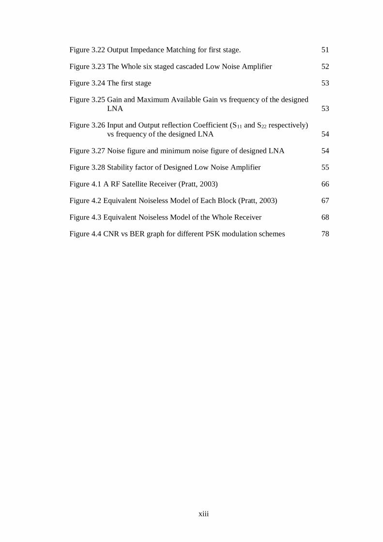
Figure 3.22 Output Impedance Matching for first stage. 51
Figure 3.23 The Whole six staged cascaded Low Noise Amplifier 52
Figure 3.24 The first stage 53
Figure 3.25 Gain and Maximum Available Gain vs frequency of the designed
LNA 53
Figure 3.26 Input and Output reflection Coefficient (S11 and S22 respectively)
vs frequency of the designed LNA 54
Figure 3.27 Noise figure and minimum noise figure of designed LNA 54
Figure 3.28 Stability factor of Designed Low Noise Amplifier 55
Figure 4.1 A RF Satellite Receiver (Pratt, 2003) 66
Figure 4.2 Equivalent Noiseless Model of Each Block (Pratt, 2003) 67
Figure 4.3 Equivalent Noiseless Model of the Whole Receiver 68
Figure 4.4 CNR vs BER graph for different PSK modulation schemes 78
xiv
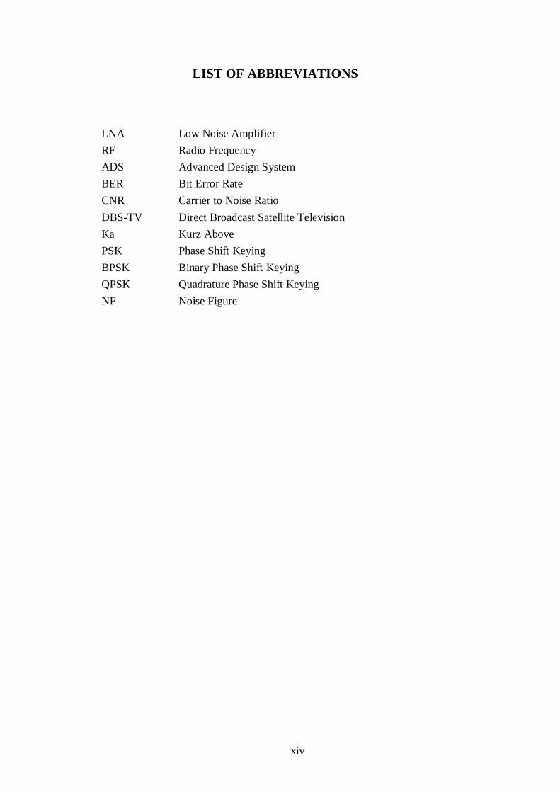
LIST OF ABBREVIATIONS
LNA Low Noise Amplifier
RF Radio Frequency
ADS Advanced Design System
BER Bit Error Rate
CNR Carrier to Noise Ratio
DBS-TV Direct Broadcast Satellite Television
Ka Kurz Above
PSK Phase Shift Keying
BPSK Binary Phase Shift Keying
QPSK Quadrature Phase Shift Keying
NF Noise Figure

xv
LIST OF SYMBOLS
I Current
V Voltage
Z Impedance
G Gain
NF Noise Figure
S11 Input Reflection Coefficient
S22 Output Reflection Coefficient
S21 Forward Gain Coefficient
Ω Ohm
Μ Micro
P
T
K
CNR
BER
Θ
Power
Noise Temperature
Kelvin
Carrier to Noise Ratio
Bit Error Rate
Angle in Degree

1
CHAPTER ONE
INTRODUCTION
1.1 BACKGROUND OF THE STUDY
The application of satellite communication system is increasing day by day in line
with all other wireless communications. In addition to Direct Broadcast Satellite TV
(DBS-TV) and telecommunication services, satellites are widely used for navigation,
remote sensing, pollution monitoring, disaster management, auto piloting etc.
Currently, C and Ku bands are completely congested and future satellite applications
are forced to move towards higher frequencies, Ka and V bands. Ka band generally
covers from 20 GHz to 30 GHz of frequencies. The ‘Ka’ is the short form of Kurtz
above implying that its bandwidth is just above the Ku. However, these bands are very
sensitive to environment and performance may degrade seriously due to tropospheric
impairment.
The tropical region, which is also known as tropics, covers the area of the
Earth which is around the Equator. It is extended from the tropic of Cancer in the
Northern hemisphere at about 23°26′13.6″ N to the tropic of Capcicorn in the south
Hemisphere at 23°26′13.6″ S. The most prominent features of this zone are high
temperature, heavy rainfall and active vertical uplift or convection of air. That’s why
it’s very common to observe high rate of precipitation with thunderstorm. These
features of tropical region actively play a role in distorting and attenuating the signals
transmitted by Satellite communication. Signals with frequency more than 10GHz,
hence the Ka band signals as well, are highly attenuated by rainfall (Saad et al, 2013).
Rain is the main impairment which contributes significant attenuation and noise
signals in tropical region )Chuan, Tian and Hon, 2015(. The rain rate that exceeds
2
0.01% of a year in this region according to latest International Telecommunication
Union statistic ITU-R P.837-7 is 90 mm/hr. At Ka band, this rate of rain causes
serious attenuation reaching more than 30dB. Hence the performance of satellite
system is required to be investigated at Ka band in the tropical region.
Satellite receiver contains Low Noise Amplifier, Bandpass Filter, Down
Converter, Local Oscillator, Mixer, Image Rejection Filter, Intermediate Frequency
Filter, Intermediate Frequency Amplifier and Demodulator. Received signals are
attenuated and distorted by noise. Low noise amplifier (LNA) is the first component
of any receiver front end circuitry. The performance of the receiver mainly depends on
it. It is the first amplifying block which boosts the weak input signal from antenna
receiver without making noise dominating it. Optimum design of LNA is the major
part in optimizing the receiver performance (Yadav, Pandey and Nath, 2016).
While there have been many LNA designs for Ka Band specification such as
that by (Curuk, Bilgic, Yegin and Ozdemir, 2016) with a gain of 22 dB, none of their
performance effects have been assessed by integrating them into a satellite receiver.
That is why this research undertakes to combine LNA design and investigation of
performance of satellite receiver operating at Ka-band in tropical climate based on
rain fade occurred and optimum design of LNA. The satellite receiver performance in
this research will be compared with that in (Qonita and Muhtadin, 2019) for same Ka
band and downlink frequency of 20 GHz.
1.2 PROBLEM STATEMENT AND ITS SIGNIFICANCE
The tropical region is characterized by features such as heavy rainfall, high
temperature, high humidity, cloud etc (Lee, Natarajan, Meng, Yeo and Ong, 2014).
All of these effects degrade the performance of satellite communication, but the most
3
significant of them is high rainfall. Any satellite communication performed above 10
GHz frequency is susceptible to high rain fade. Since C and Ku bands are already
congested, future applications are forced to move to Ka and V bands. In Ka band,
which operates at frequency above 20 GHz, rain fade is severe and may reach up to 30
dB in tropical region.
Rain causes not only attenuation, but also contributes in increasing noise.
Every droplet of rain acts as noise source. Rain increases system temperature of RF
receiver and thus decreases the CNR ratio of the signal received by the receiver,
which in turn degrades BER performance of the received signal.
That is why the RF receiver’s performance at Ka band in rainy situation needs to
be investigated. LNA is one of the most significant parts in a satellite receiver. An
LNA of a good configuration can significantly improve noise performance of the
whole satellite receiver by minimizing the noise contributed by stages subsequent to
it. There have been many LNA designs specified to work at Ka band but none of them
has been assessed by integrating them into a RF satellite receiver.
In this research, An LNA is designed and integrated into a RF receiver and the
BER performance of the receiver is investigated for different availabilities and for
different modulation schemes at different polarizations for tropical region thus
enabling a novel and more comprehensive study of the performance of a RF satellite
receiver at Ka band. In designing LNA, the designs proposed by (Curuk, Bilgic, Yegin
and Ozdemir, 2016) have been considered as benchmarks. The performance of the
Satellite receiver in this research will be compared with that of found in (Qonita and
Muhtadin, 2019) for Ka band at the same downlink frequency of 20 GHz.
4
1.3 RESEARCH OBJECTIVES
The study aimed to achieve the following objectives:
1- To design a low noise amplifier with a gain of at least 30 dB and noise
figure less than 2.8 dB at the operating at Ka-band with 20 MHz
bandwidth.
2- To estimate the rain fades at Ka-band for various outage probabilities of
and for vertical, horizontal and circular polarizations in a tropical climate.
3- To evaluate the performance of the satellite receiver using designed LNA
at Ka band based on estimated rain fades.
1.4 RESEARCH METHODOLOGY
The main steps of the methodology followed in this research are as follows:
Step 1: To Design an LNA using Advanced Design System (ADS)
- Selecting a proper transistor
- Finding out bias point
- Designing RF choke
- Designing first stage of LNA using transistor and RF choke
- Designing input impedance matching network
- Adding stages until optimum noise and gain are achieved
Step 2: To estimate rain fade for different outages for vertical, horizontal and circular
polarizations
- Finding out rain rate that exceeds 0.01% of a year using digital map given
in ITU-R P.837-7.
- Calculating rain fade for rain rate that exceeds 0.01% of a year using
instructions given in ITU-R P.618-13.
- Finding out other rate of outages from that of 0.01% using formula given
in ITU-R P.618-13.
Step 3: To find out BER performance of the receiver for different outage rates and
different polarizations
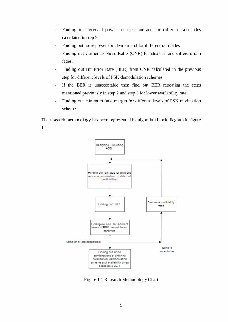
5
- Finding out received power for clear air and for different rain fades
calculated in step 2.
- Finding out noise power for clear air and for different rain fades.
- Finding out Carrier to Noise Ratio (CNR) for clear air and different rain
fades.
- Finding out Bit Error Rate (BER) from CNR calculated in the previous
step for different levels of PSK demodulation schemes.
- If the BER is unacceptable then find out BER repeating the steps
mentioned previously in step 2 and step 3 for lower availability rate.
- Finding out minimum fade margin for different levels of PSK modulation
scheme.
The research methodology has been represented by algorithm block diagram in figure
1.1.
Figure 1.1 Research Methodology Chart

6
1.5 RESEARCH SCOPE
This work focuses on the down link of Ka-band with centre frequency of 20 GHz and
bandwidth of 20 MHz. The LNA in this work has been designed for this specification
with an aim of minimum 30 dB of gain and noise figure less than 2.8 dB. The rain
fade and BER performance have been estimated considering the climate of Malaysia.
BER performance has been estimated for Phase Shift Keying (PSK) modulation
schemes (BPSK, QPSK, 8-PSK, 16-PSK and 32-PSK) and for various outage
probabilities and for vertical, horizontal and circular polarizations.
1.6 THESIS ORGANIZATIONS
Chapter 1 of this thesis gives an introduction where research background, research
problem statement, research objective, methodology and scope have been delineated.
Chapter 2 presents literature review in details. Chapter 3 discusses the details of
designing of proposed Low Noise Amplifier and its performance. Chapter 4 is on the
second and third objective of the research namely, estimating rain fade at different
availabilities and evaluating BER performance for different modulation schemes.
Chapter 5 is about conclusion and suggesting future work.

7
CHAPTER TWO
LITERATURE REVIEW
2.1 INTRODUCTION
This chapter presents an overview of a satellite receiver. It includes different
approaches to Low Noise Amplifier design. The different factors leading to signal
attenuation when signal is transmitted through channel are discussed in brief. This
phenomenon is also known as channel transmission impairment. This chapter also
describes how to estimate rain fade step by step using the updated model proposed by
International Telecommunication Union in details.
2.2 SATELLITE RECEIVER
A RF receiver is an essential component of satellite communication. It receives the
transmitted signal and processes it to extract the replica of the original transmitted
signal from the received signal, which becomes distorted as the transmitted signal
travels through the channel because of attenuation and noise. A simplified block
diagram of a satellite receiver is shown in Figure 2.1.
Figure 2.1: A Superheterodyne Receiver Block Diagram (Pratt, 2003)

8
Most of the satellite systems now-a-days use superheterodyne receiver. A RF receiver
generally consists of three parts namely, front end, IF amplifier and a demodulator and
baseband section. Front end is composed of LNA, mixer and oscillator. IF amplifier
section consists of IF amplifiers and filters. The demodulator and baseband section
contains demodulator and other stuffs (Pratt, 2003). Low Noise Amplifier is situated
after the receiver antenna. It amplifies the received attenuated signal and amplifies it
adding a minimal amount of noise from itself. The bandpass filter filters out signals
outside of the desired bandwidth. The downconverter consists of a mixer and local
oscillator. The signal amplified by the LNA is mixed with signal of lower frequency
produced by local oscillator and converted down to a fixed intermediate frequency
that is suitable to process for the receiver circuitry. The signal then can be amplified
and filtered more accurately (Pratt, 2003).
2.3 LOW NOISE AMPLIFIER
Low noise amplifier is a very significant component in the front end part of the
receiver. It receives the transmitted signal, whose power becomes very low during the
transmission because of the attenuation and noise in the channel, and amplifies the
received signal and adds noise of a low level from itself. Low Noise Amplifier plays a
very important role in decreasing the overall noise of the satellite receiver. If Low
Noise Amplifier has a sufficiently large gain, it helps to undermine the noise
contributed by the stages situated after the LNA in the receiver to an extent where
their contributed noise can be almost ignored. In the following from 2.3.1 to 2.3.9,
different approaches to designing Low Noise Amplifier presented by different
researchers have been described in brief.
9
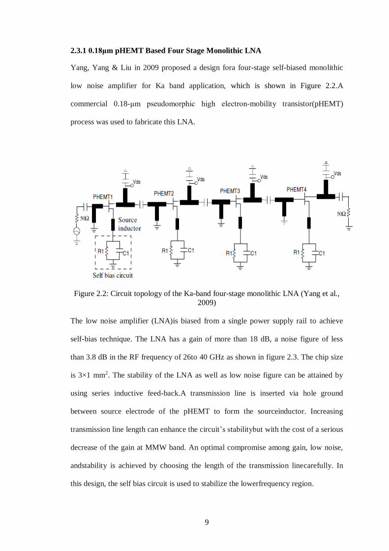
2.3.1 0.18μm pHEMT Based Four Stage Monolithic LNA
Yang, Yang & Liu in 2009 proposed a design fora four-stage self-biased monolithic
low noise amplifier for Ka band application, which is shown in Figure 2.2.A
commercial 0.18-μm pseudomorphic high electron-mobility transistor(pHEMT)
process was used to fabricate this LNA.
Figure 2.2: Circuit topology of the Ka-band four-stage monolithic LNA (Yang et al.,
2009)
The low noise amplifier (LNA)is biased from a single power supply rail to achieve
self-bias technique. The LNA has a gain of more than 18 dB, a noise figure of less
than 3.8 dB in the RF frequency of 26to 40 GHz as shown in figure 2.3. The chip size
is 3×1 mm2. The stability of the LNA as well as low noise figure can be attained by
using series inductive feed-back.A transmission line is inserted via hole ground
between source electrode of the pHEMT to form the sourceinductor. Increasing
transmission line length can enhance the circuit’s stabilitybut with the cost of a serious
decrease of the gain at MMW band. An optimal compromise among gain, low noise,
andstability is achieved by choosing the length of the transmission linecarefully. In
this design, the self bias circuit is used to stabilize the lowerfrequency region.