design of a low-cost drilling rig (cranfield - burrows g)
TRANSCRIPT

Cranfield University R.G. Burrows, 2006 i
Abstract
13 countries from sub-Saharan Africa are currently not on target to attain the
Millennium Development Goal to �half those without access to safe drinking water by
2015�.
One of the reasons for this is the high cost of well installation.
Hand operated drilling can provide a cheap alternative to mechanised conventional
drill technology, with the potential to deliver wells which are affordable to farmers and
local village groups. Uptake of the method could lead to growth of private sector water
provision, if enough demand could be created to sustain it. To encourage this potential
drill rigs which are as cheap, efficient and adaptable as possible need to be accessible
to the private sector. In this study an attempt is made to design such a rig.
This study explores the advantages and limitations of hand operated drilling, describes
hand operated drill rigs currently in use and analyses drilling constraints in the
hydrogeological domains of Sub-Saharan Africa.
A drill rig was designed following set criterion, combining 4 hand operated drilling
techniques: percussion, augering, sludging and jetting. Two drill bits were designed to
improve jetting performance in clay. The drill bits and parts of the kit were then tested
and 6 boreholes were drilled at Cranfield University, Silsoe.
From the results of the tests, a comparison was made of the effectiveness of augering,
sludging and jetting in differing soil conditions, the rig and bits were modified to
improve performance and hand operated drilling methods were contrasted with more
conventional forms of drilling.
Jetting was found to be the most effective technique in drilling through the soils
constituting sand and clay, it was also found to compare favourably with conventional
forms of drilling, proving that hand operated drilling can play an important role in the
provision of clean water to Sub-Saharan Africa.
Cranfield University R.G. Burrows, 2006 ii
Acknowledgements First I would like to thank my supervisor Professor Richard Carter for his solid guidance and encouragement. I would also like to express my gratitude to Nigel Janes for all his time, effort and help before, during and after the field testing, despite his bad leg! I would like to thank my brother Kenan for his muscle power, strength and good sense. Thanks also to Phil Trolley for his technical skill and jovial spirit and Margaret Boon for all her help in the soils laboratory. Many thanks to Terry Waller, who was so helpful and forthgiving with information about his drill rig and the work he is undertaking with it. I am grateful also to Robin Hazell, Richard Cansdale and Peter Ball for the information that they provided me through conversation and email. Lastly I would like to thank many of my CWS course mates for helping me with the field work. A special thanks to Genis Duch who shared my interest in low cost drilling techniques throughout the summer.

Cranfield University R.G. Burrows, 2006 iii
�If the axe is dull and its edge unsharpened, more strength is needed
but skill will bring success.� (Ecclesiastes 10,10)
Cranfield University R.G. Burrows, 2006 iv
Table of Contents 1 INTRODUCTION.......................................................................................................................1
1.1 CONTEXT AND BACKGROUND................................................................................................1 1.2 THE DREAM..........................................................................................................................3 1.3 THE THESIS�S AIMS & OBJECTIVES .......................................................................................3
2 METHODOLOGY......................................................................................................................5 2.1 INTRODUCTION .....................................................................................................................5 2.2 LITERATURE REVIEW ............................................................................................................5 2.3 EQUIPMENT SELECTION FOR �DESIGN RIG� ..............................................................................6 2.4 QUESTIONS RAISED ...............................................................................................................6 2.5 FIELD WORK .........................................................................................................................7
3 LITERATURE REVIEW ...........................................................................................................9 3.1 GEOLOGY AND PEDOLOGY ....................................................................................................9
3.1.1 The Sedimentary Rocks ....................................................................................................9 3.1.2 The Crystalline Basement Rocks.....................................................................................10 3.1.3 Implications for drilling.................................................................................................11
3.2 REVIEW OF HAND OPERATED DRILLING TECHNIQUES ..........................................................12 3.2.1 Percussion /Cable tool...................................................................................................12 3.2.2 Driving..........................................................................................................................12 3.2.3 Augering........................................................................................................................13 3.2.4 Jetting ...........................................................................................................................13 3.2.5 Sludging ........................................................................................................................14
3.3 REVIEW OF EXISTING HAND OPERATED DRILLING TECHNOLOGIES .......................................15 3.3.1 Vonder Rig:...................................................................................................................16 3.3.2 Emas Rig.......................................................................................................................16 3.3.3 Pounder Rig ..................................................................................................................17 3.3.4 The Rota-sludge Rig.......................................................................................................18 3.3.5 The Stone Hammer Rig ..................................................................................................19 3.3.6 The Baptist Rig ..............................................................................................................20
4 TECHNOLOGY SELECTION / DESIGN CRITERIA ...........................................................22 4.1 INTRODUCTION ...................................................................................................................22 4.2 THE EFFECTIVENESS OF THE EQUIPMENT : ............................................................................22
4.2.1 Drilling speed................................................................................................................22 4.2.2 Ability to penetrate different lithologies..........................................................................22 4.2.3 Maximum Depth ............................................................................................................23 4.2.4 Hole Diameter...............................................................................................................23 4.2.5 Hole Straightness...........................................................................................................23
4.3 THE AVAILABILITY OF RESOURCES.......................................................................................24 4.3.1 Financial Capital...........................................................................................................24 4.3.2 Social Capital................................................................................................................24 4.3.3 Skills .............................................................................................................................24 4.3.4 Materials.......................................................................................................................24 4.3.5 Energy...........................................................................................................................24 4.3.6 Water ............................................................................................................................25 4.3.7 Transport ......................................................................................................................25
4.4 COST PER WELL ..................................................................................................................25 4.5 THE REPLICABILITY OF THE TECHNOLOGY............................................................................26
5 THE RIG DESIGN....................................................................................................................27 5.1 THE DESIGN RIG .................................................................................................................27 5.2 THE MATERIALS INVENTORY ..............................................................................................30 5.3 SELECTING THE DESIGN RIG KIT .........................................................................................31
Cranfield University R.G. Burrows, 2006 v
5.3.1 Drill Pipe ......................................................................................................................31 5.3.2 Tools .............................................................................................................................33 5.3.3 Drill pipe stabilisation ...................................................................................................33 5.3.4 Drill pipe lifting device ..................................................................................................33 5.3.5 Temporary Casing .........................................................................................................34 5.3.6 Well Consumables .........................................................................................................34
5.4 DRILL BITS .........................................................................................................................35 5.4.1 The Clay problem ..........................................................................................................35 5.4.2 Hard Consolidated formations .......................................................................................35 5.4.3 Gravels..........................................................................................................................36 5.4.4 Drill Bit Design .............................................................................................................36
5.5 SPECIALIST EQUIPMENT ......................................................................................................38 6 RESULTS..................................................................................................................................40
6.1 THE TEST KIT ......................................................................................................................40 6.2 THE FIELD TESTS ................................................................................................................41 6.3 COMPARISON OF THE DIFFERENT DRILL TECHNIQUES EFFECTIVENESS....................................41 6.4 CALCULATING WATER USAGE ............................................................................................45 6.5 CALCULATING MAXIMUM DEPTH ........................................................................................46 6.6 ESTIMATING COST...............................................................................................................47
7 DESIGN IMPROVEMENTS....................................................................................................48 7.1 MODIFICATIONS TO THE RIG DESIGN ...................................................................................48 7.2 MODIFICATIONS TO THE BIT DESIGNS ..................................................................................49
7.2.1 Cross chisel bit ..............................................................................................................49 7.2.2 Dart valve bit.................................................................................................................50
8 DISCUSSION & CONCLUSIONS ...........................................................................................52 9 GENERAL RECOMMENDATIONS.......................................................................................55 10 REFERENCES..........................................................................................................................56 APPENDIX 1: REVIEW OF EXISTING HAND OPERATED DRILLING TECHNIQUES..........60 APPENDIX 2: PHOTOS....................................................................................................................62 APPENDIX 3: ITEMS USED TO CONSTRUCT THE TEST DRILL RIG.....................................68 APPENDICES 4: BOREHOLE LOGS..............................................................................................69
BOREHOLE LOG 1 � JETTING USING THE CROSS CHISEL BIT .................................................................69 BOREHOLE LOG 2 � JETTING USING THE OPEN PRONGED BIT...............................................................70 BOREHOLE LOG 3 � JETTING USING THE DART VALVE BIT...................................................................70 BOREHOLE LOG 4 � SLUDGING USING CROSS CHISEL BIT ....................................................................71 BOREHOLE LOG 5 �SLUDGING USING THE OPEN PRONGED BIT ............................................................72 BOREHOLE LOG 6 � AUGURED HOLE..................................................................................................72
APPENDIX 5: BOREHOLE LOG DATA.........................................................................................74 APPENDIX 6: DRILL BIT DESIGNS...............................................................................................79 APPENDIX 7: CWS DRILLING WEEK INFORMATION .............................................................82
Cranfield University R.G. Burrows, 2006 vi
List of Tables and Figures
Tables TABLE 1:CONVENTIONAL DRILLING BOREHOLE COSTS (INFORMATION COURTESY OF ALITO (2006)).......2 TABLE 2: SUMMARY OF DRILLING TECHNIQUES ..................................................................................15 TABLE 3: MATERIALS INVENTORY.....................................................................................................30 TABLE 4: SUMMARISED FIELD TEST RESULTS......................................................................................41 TABLE 5: WELL & EQUIPMENT COSTS ................................................................................................47 TABLE 6: TIME DRILLED COMPARED WITH DEPTH ...............................................................................74 TABLE 7: TIME COMPARED TO MATERIAL REMOVED (M³) ....................................................................76 TABLE 8: LABORATORY RESULTS FOR BOREHOLE SAMPLES SHOWING OVERALL TEXTURAL COMPOSITION
OF SOIL ....................................................................................................................................77 TABLE 9: BOUYOUCOS TEST RESULTS ................................................................................................77 TABLE 10: PERCUSSION DRILLING LOG ..............................................................................................82 TABLE 11: ROTARY MUD DRILLING LOG ...........................................................................................83
Figures FIGURE 1:HYDROGEOLOGICAL DOMAINS OF SUB-SAHARAN AFRICA (MACDONALD ET AL. 2001) ..........9 FIGURE 2: PRINCIPAL CONSTITUENTS OF SEDIMENTARY ROCKS (FROM NICHOLS 1999) ........................10 FIGURE 3: THE RIG - SET UP FOR JETTING............................................................................................28 FIGURE 4: THE RIG - SET UP FOR AUGERING ........................................................................................28 FIGURE 5: THE RIG - SET UP FOR SLUDGING ........................................................................................29 FIGURE 6: THE RIG - SET UP FOR PERCUSSION .....................................................................................29 FIGURE 7: THE RIG � IMPROVED FOR JETTING .....................................................................................48 FIGURE 8: THE RIG - IMPROVED FOR SLUDGING ..................................................................................49 FIGURE 9: THE IMPROVED CROSS CHISEL BIT ......................................................................................50 FIGURE 10: THE IMPROVED DART VALVE BIT ......................................................................................51 FIGURE 11:HAND OPERATED DRILLING TECHNIQUES (ELSON & SHAW, 1995)......................................60 FIGURE 12: DRILL LOG SAMPLES CLASSIFIED USING THE ISSS SOIL TEXTURAL CLASSIFICATION ...........78 Photos PHOTO 1: HIGH PARTICIPATION IS REQUIRED TO WORK THE VONDER RIG IN THE LOWER TANA RIVER
AREA, KENYA. (KENYA WATER FOR HEALTH ORGANISATION WEBSITE, 2006) ............................16 PHOTO 2: THE EMAS DRILL BIT (BUDDHISTISCHE HAUS , 2005) ..........................................................17 PHOTO 3: THE POUNDER RIG, TAKEN AT CRANFIELD UNIVERSITY, SILSOE, 28/06/06 ..........................18 PHOTO 4: THE STONE HAMMER BIT, TAKEN FROM NWP (2006)...........................................................19 PHOTO 5: THE BAPTIST DRILL BIT ......................................................................................................21 PHOTO 6: THE BAPTIST RIG MOTORISED ............................................................................................21 PHOTO 7: THE BAPTIST RIG IN ACTION ..............................................................................................21 PHOTO 13: THE CROSS CHISEL BIT......................................................................................................37 PHOTO 14: THE DART VALVE BIT .......................................................................................................38 PHOTO 8: THE TEST DRILL KIT SET UP TO JET. .....................................................................................40 PHOTO 9: THE TEST DRILL KIT SET UP TO SLUDGE ...............................................................................62 PHOTO 10: SLUDGING IN ACTION .......................................................................................................62 PHOTO 11: JETTING IN ACTION...........................................................................................................63 PHOTO 12: AUGERING IN ACTION.......................................................................................................63 PHOTO 15: THE AUGER BITS...............................................................................................................64 PHOTO 16: THE OXFAM AUGER KIT....................................................................................................64 PHOTO 17: THE POINT VALVE BIT PRIOR THE 6 HOLES .........................................................................65 PHOTO 18: THE POINT VALVE BIT WITH HOLES BUT WITH VALVE SHUT ................................................65 PHOTO 19: THE POINT VALVE BIT � VALVE OPEN ................................................................................66

Cranfield University R.G. Burrows, 2006 vii
PHOTO 20: THE POINT VALVE BIT � POST DRILLING.............................................................................66 PHOTO 21: THE OPEN PRONGED BIT � POST DRILLING..........................................................................67 PHOTO 22: JETTING USING PLASTIC PIPE .............................................................................................67 Graphs GRAPH 1: COMPARISON OF DRILL TECHNIQUES...................................................................................42 GRAPH 2: COMPARISON OF DRILL TECHNIQUES EFFECTIVENESS IN DIFFERING LITHOLOGIES .................43 GRAPH 3: COMPARING TECHNIQUES BY STANDARDISING BOREHOLE DIAMETERS TO 100MM.................44 GRAPH 4: COMPARISON OF CONVENTIONAL DRILLING WITH HAND OPERATED DRILLING TECHNIQUES...45
Designs
DESIGN 1: CROSS CHISEL BIT .............................................................................................................79 DESIGN 2: DRILL STABILISER ............................................................................................................80 DESIGN 3: DART VALVE BIT...............................................................................................................81
Cranfield University R.G. Burrows, 2006 viii
Definitions
Technique: A method Technology: A piece of hardware, using certain techniques Rig: A technology designed to drill boreholes
Symbols min/m = minutes per metre $/m = dollars per metre Ø = diameter Ft = feet Л = pie � = inch Abbreviations OD = outer diameter ID = internal diameter MDG = Millenium Development Goals WHO = World Health Organisation DFID = Department for International Development ISSS = International Society of Soil Science NWP = Netherlands Water Partnership GI = galvanised iron VLOM= Village Level Operation & Maintenance
Cranfield University R.G. Burrows, 2006 1
�Design of a low cost, hand operated drill rig appropriate for adoption by sub-Saharan
Africa�s private sector.�
1 Introduction
1.1 Context and Background An estimated 1.1 billion people lack access to a safe water supply (DFID, 2006),
which approximates to around a 6th of the world�s population. The African people are
worst affected with an estimated 38% of the population unserved (DiGiano et al.
2004).
A lack of access to safe water has severe consequences on a population�s health. The
Millennium Development Goals (MDG) Task Force (2005) estimated that at any one
time half the population of the developing world is suffering from a water-related
illness (DFID 2006). An inadequate water supply further disbenefits communities�
productivity, education and well being. This has implications on a region�s economy
and stability.
The MDG target to halve �by 2015, the proportion of people without sustainable
access to safe drinking water� (Goal 7 Target 10) was adopted by 189 nations in 2000.
In order to meet this goal WHO estimates that an additional 260 000 people per day
need to gain access to improved water sources until the year 2015 (WHO, 2004).
Achieving the MDG in sub-Saharan Africa is currently off track (DFID 2006).
According to Lenton & Wright (2004) 25 countries are either lagging behind or are
even slipping backward in their progress toward attaining the MDG targets, 13 of
these are from sub-Saharan Africa.

Cranfield University R.G. Burrows, 2006 2
Reasons for this lack of progress include, Africa�s continued population growth
increasing demand, climate change reducing the amount of water available, lack of
funding (which is heavily dependent on foreign aid or debt relief (Danert, 2003)),
corruption and high costs of providing contractor drilled wells.
It is the high cost of well provision that this thesis is concerned with.
Well costs � involving the private sector
Table 1 illustrates a costs estimate for contractors to drill a 141m hole in the Oromia
region, Ethiopia. Table 1:Conventional drilling borehole costs (information courtesy of Alito (2006)) Heavy Rig Medium Rig Light Rig
Depreciation US$/m 57.94 41.98 29.99
Transport US$/m 4.51 1.38 0.98
Manpower US$/m 15.81 10.42 6.83
Consumables US$/m 5.43 4.91 3.56
Overheads US$/m 25.11 17.61 12.41
Sub Total US$/m 108.79 76.30 53.77
Drilling
Component
US$ 10,895 7,037 4,632
Total Cost of
Well
US$ 56,162 43,175 35,608
Cost per meter US$ 398 306 253
Such costs are not affordable for the local population and therefore it is their
government and external international aid agencies that pay, this lack of affordability
of course leads to many wells not being built at all.
Recent thought in the development sector has been moving away from aid, towards
that of creating an enabling environment to help people help themselves. Community
driven development is the catch phrase used by the World Bank (World Bank, 2006)
and large trusts such as the Bill and Melinda Gates Foundation are concentrating on
Cranfield University R.G. Burrows, 2006 3
funding water & sanitation projects that involve private sector participation (spoken
conversation with Garandeau, 2006).
For local populations and the private sector to become involved in the provision and
payment of their own wells, the costs of well provision needs to be dramatically lower
than the figures illustrated in Table 1.
1.2 The Dream
Hand operated drilling may be an answer; hand operated drill rigs constructed from
locally available material using local resources are not only cheap (the Baptist drill rig
costs around $250 dollars to construct [Waller, 2006]), but also have low operational
costs due to being constructed from cheap, easily available and sustainable spare
parts. Low costs mean new private sector entrepreneurs require only small start up
capital to get their business off the ground and make them profitable.
Wells installed by hand operated drill rigs would cost villagers as little as $50-$200
(see section 6.6) which conceivably the villagers themselves could pay, thereby
encouraging a demand response approach to water provision and also encouraging
communities to work together. This would create ownership over their well and
thereby encourage the wells sustainability through successful village level operation
& maintenance (VLOM).
1.3 The Thesis�s Aims & Objectives The aim of this thesis is to design a drill rig kit suitable for adoption by developing
world businesses and entrepreneurs, who can then provide an affordable service of
water provision to farmers and villages in their local region. The location this thesis
focuses on is that of sub-Saharan Africa.
The drill will need to penetrate various different ground conditions. There are
currently five hand operated drilling techniques; percussion, augering, sludging,
jetting or driving. The �design kit� will incorporate the best of the existing technology
to give the drill operator the best tools to make the business as flexible and as
profitable as possible.

Cranfield University R.G. Burrows, 2006 4
The hope is that with affordable well costs, individuals and villages maybe tempted to
invest in wells, leading to private sector growth.
Low costs associated with drill rig construction will also encourage larger numbers of
businesses to set-up and operate profitably, thereby increasing competition in the
market.
Competition will improve private sector efficiency, quality of service, professionalism
and lead to greater consumer choice and service provision.
Cranfield University R.G. Burrows, 2006 5
2 Methodology
2.1 Introduction
To design an appropriate hand operated drill rig for the private sector in sub-Saharan
Africa the following methodology was followed:
Information concerning existing drill techniques and technologies was reviewed as
was information describing sub-Saharan Africa�s geological terrains, which overlie
and contain the aquifers.
Individuals who work in the field of low cost drilling were contacted for further
insight.
An attempt was then made to combine the strengths of the differing technologies
investigated to make the �design rig�; this was done following a set of controlling
parameters (see Section 4).
Field tests were then conducted to give the author greater insight into the drilling
techniques, to test elements of the �design rig�, to test two designed drill bits and to
compare three different hand operated drilling methods in clay.
2.2 Literature Review
The following information was sought:
• Current hand operated drilling techniques.
• Current hand operated drill rig technology in use in the developing world.
• Sub-Saharan Africa�s geological terrains which overlie and contain the
aquifers.
Information was gathered from the following sources:
• Cranfield University library literature
• Cranfield MSc unpublished theses
• Internet using www.google.com & www.ixquick.com
• Geological Society of London library literature.
Cranfield University R.G. Burrows, 2006 6
• Communication with individuals involved or working with low cost drilling
technology.
2.3 Equipment selection for �design rig�
When selecting the most appropriate equipment for the drill rig kit, the following
design parameters were followed, believed to be the most important factors leading to
the success of the rig design:
1. The effectiveness of the equipment: drilling speed, ability to penetrate
different lithologies, maximum depth, hole diameter, hole straightness.
2. The availability of resources: financial capital, social capital, materials, skills
available locally to construct and run the rig, energy availability, water
availability, transport availability
3. Cost per well: The initial cost of the equipment and the running costs
4. The replicability of the technology; simplicity and ease of manufacturing and
operating the equipment.
Equipment for the �design rig� was selected by taking the best features of existing
technologies, found in the literature review, and attempting to combine them into one
piece of kit, whilst following the design parameters listed above.
To aid this process a materials inventory was formulated listing, for each technique,
all the necessary equipment and materials needed to construct a rig. These inventories
were then compared and items common to the different techniques were selected to
form a skeletal structure of the design rig, before detail was decided.
Two multi-purpose drill bits were also designed in accordance with the above listed
parameters.
2.4 Questions raised The literature review and the process of selecting the right equipment for the rig
design raised a couple of questions which were thought important to explore further.

Cranfield University R.G. Burrows, 2006 7
• Nothing was found in the literature review which directly compared the
effectiveness of different hand operated drilling techniques in different soil
types. Did one technique have any significant advantage over any of the other
techniques when penetrating certain soil conditions?
• The literature review uncovered contradictory reports on jetting rigs capability
of penetrating clay. Was it possible to jet through clay? Could bits be designed
to improve the performance of jetting rigs through clay soils?
2.5 Field work
Field work was carried out so as to:
• Give the author greater insight into the challenges associated with drilling
boreholes using different human powered techniques.
• Test elements of the �design rig� out in the field.
• Compare and contrast different techniques capabilities to penetrate clay, sand
and more consolidated layers of soil.
• Test out two drill bits designed by the author and their ability to jet through
clay.
The field work was undertaken using three different types of hand operated drilling
techniques; jetting, sludging and augering. A rig which incorporated elements of the
design rig was constructed from material that was available at Cranfield University to
carry out these tests (see photos 11, 12 13&14, annex 2).
To test out the augering drilling method an Oxfam auger kit was utilised in
conjunction with the design rig (see photo 16, annex 2).
Time and depth measurement were taken during the testing and a sample of the
excavated material was collected every 0.5m. This material was later analysed in the
laboratory to determine its exact constitution using the Bouyoucos method and sieve
analysis.
Percussive drilling (using a Dando rig) and rotary drilling (using a 202 PatDrill rig)
had previously been undertaken by the CWS 2005/06 group during a drilling week
practical from Monday 22nd to Friday 26th May 2006. The drilling had been undertaken

Cranfield University R.G. Burrows, 2006 8
in the same locality and geology as this thesis� field work and therefore made useful
comparative data.
Cranfield University R.G. Burrows, 2006 9
3 Literature Review
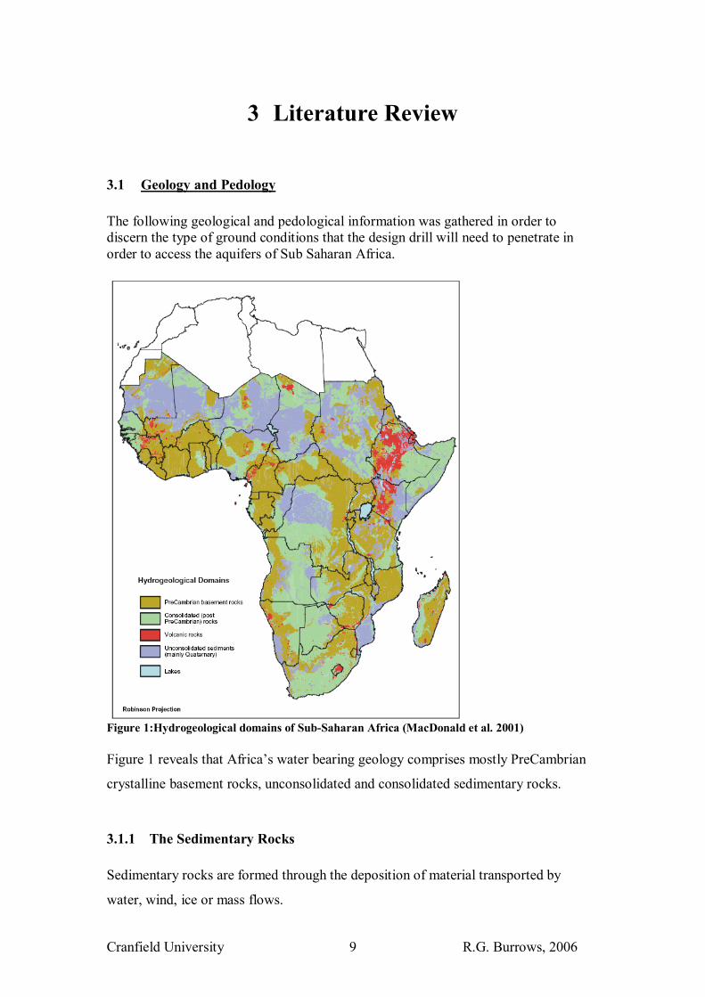
3.1 Geology and Pedology The following geological and pedological information was gathered in order to discern the type of ground conditions that the design drill will need to penetrate in order to access the aquifers of Sub Saharan Africa.
Figure 1:Hydrogeological domains of Sub-Saharan Africa (MacDonald et al. 2001) Figure 1 reveals that Africa�s water bearing geology comprises mostly PreCambrian
crystalline basement rocks, unconsolidated and consolidated sedimentary rocks.
3.1.1 The Sedimentary Rocks Sedimentary rocks are formed through the deposition of material transported by
water, wind, ice or mass flows.

Cranfield University R.G. Burrows, 2006 10
Figure 2: Principal constituents of sedimentary rocks (from Nichols 1999)
Figure 2 outlines the principal types of material that make up sedimentary rocks. The
depositional environment influences the size, shape and distribution of particles
deposited (Nichols 1999), low energy environments deposit fine material whilst high
energy environments deposit coarser grained material.
The sedimentary deposits have undergone varying degrees of induration depending on
the amount and degree of pressure they have been exposed too. Generally the older
the rock or the deeper the material is buried, the more consolidated it will be.
3.1.2 The Crystalline Basement Rocks The crystalline basement rocks comprise both metamorphic and igneous rock. Where
the rock is still relatively fresh and unweathered hand operated drilling is not feasible,
however much of the basement rock has been subject to many years of in-situ
weathering which has broken down the existing parent rock and formed a material
known as tropical residual soil (or regolith), which lies on top of the crystalline
basement rock. This tropical residual soil can potentially be drilled by hand operated
drill rigs to access shallow aquifers contained within the weathered profile.
One of the main weathering processes is that of leaching and the precipitation of
minerals, concentrating certain minerals together to create new types of soil horizon.
Cranfield University R.G. Burrows, 2006 11
In drilling terms, four main types of material were found by the author to be
associated with tropical residual soils:
Duricrust or Pedocrete also known as Laterite: Hardened soil horizons formed by
the accumulation of iron (ferricrete) and alumina (alucrete), or by the precipitation of
calcite (calcrete), dolomite (dolocrete) or gypsum (gypcrete) (Fookes,1997).
Saprolite: Created by the leaching of silica, bases and iron (up to half the rock mass
can be lost) forming a weak, friable, chemical weathered material. eg. podzol or the
white sands of Borneo (Fookes, 1997).
Clays : Formed through the deposition and reaction of some of the leached minerals
such as Silica and Alumina. Clays commonly formed include smectite (found in
Fersiallitic soils), kaolinite (associated with Ferruginous soils) and gibbsite
(associated with Ferrallitic soils)(Fookes, 1997).
Saprock: Comprising the slightly altered/rotten bedrock with less than 20% of
weatherable minerals altered (Pirsa Minerals, 2006).
3.1.3 Implications for drilling The unconsolidated sedimentary rock and weathered saprolite rock are potentially
the easiest material to drill through and should cause the least trouble for operators
working with hand operated drilling kits, the exceptions being gravel and running
sand.
Gravels can create problems for drill operators by being a difficult material to remove
from the hole.
Running sand (unconsolidated sand under the water table) can also cause problems
for the operator by flowing into the hole, making it very difficult to keep the hole
open and to make downward progress.
The clays associated with tropical residual soils and sedimentary rock can be a hard
work to penetrate for a hand operated drill rig. They can absorb or dissipate energy
when impacted, block the drill bit and form clay collars around the bit. Clay can also
expand, causing the hole to close or trap casing down-hole.
The hard bands of mineral deposit or duricrusts can also pose a problem for a hand
operated rig. Much energy is required to break down this material and manpower

Cranfield University R.G. Burrows, 2006 12
alone can take a long time to transfer sufficient energy into the rock. This problem is
also associated with saprock and consolidated sedimentary rocks.
Old consolidated sedimentary rocks are often quite well fractured due to having
experienced ground movement since they were laid down. Large fractures within the
rocks can cause problems for drillers when using drill mud. The fractures can drain
the drill fluid away causing a loss of fluid circulation in the hole.
3.2 Review of Hand Operated Drilling Techniques Five hand operated drilling techniques are currently practiced. These techniques were
reviewed, their strengths and limitations identified in order to try and capture the main
advantages of each technique in the design rig. The techniques are discussed
individually below and summarised in table 2.
3.2.1 Percussion /Cable tool Developed by the Chinese 4000 years ago, they used to drill wells to a depth of 3000ft
(915m), although such well could take 2-3 generations to complete (Driscoll, 1986).
Percussion drilling consist of a cutting or hammering tool or bit attached to the bottom
of a pipe or cable, which is repeatedly picked up and then allowed to fall by gravity
and impact on the bottom of the hole (see figure 11, appendices 1).
Advantages: Can penetrate almost all different types of lithology
Disadvantages: Slow and laborious
Need to keep removing drill tools to excavate material from hole
Often need to drive in temporary casing to keep the hole open, this casing then needs
to be removed after drilling.
3.2.2 Driving Similar to the percussion technique: a point attached to the bottom end of a string of
pipes is driven into the ground, material is not removed from the hole but is pushed to
the sides, similar to a nail being driven into a piece of wood.
Cranfield University R.G. Burrows, 2006 13
Advantages: Fast penetration rates in soft material
No need to remove material from hole.
Disadvantages: Special well points and heavy drive pipe are needed and may not be
locally available.
Hard formations cannot be penetrated.
3.2.3 Augering Specially shaped bits are rotated and simultaneously forced downward to bore into the
ground. The bit is then pulled up and out of the hole to remove the augered material.
Different types of auger bits can tackle different types of lithology depending on their
shape (see figure 11, appendix 1). Augering is usually carried out using a heavy tripod
fitted with a hand winch, using 100-150mm (exceptionally up to 250mm) diameter
augers and a 25-50mm drill rod (Carter, 2005).
Advantages: Can shear off material � effective at penetrating soft materials
specifically clay.
Disadvantages: Need to keep removing the pipes to remove augered material, this
process is time consuming and laborious.
This method cannot penetrate collapsing sands, gravels or hard formation (Danert,
2006).
In collapsing formations temporary casing is needed to keep hole open
3.2.4 Jetting Water is pumped down a pipe and jetted out of the bottom. This water serves two
purposes; primarily the water clears cuttings and transports them to the surface;
secondly the jet fluidises unconsolidated sediment thereby allowing the pipe easier
access downward through the underlying material (see figure 11 appendix 1 for
illustration). The water as it passes up the outer annulus also washes the sides of the
hole creating a larger hole diameter. The diameter of the hole is controlled by the
diameter size of the pipe, the velocity of the water that passes up hole and the
surrounding lithology.
A number of adaptions of this method are practiced and detailed in appendix 1.
Cranfield University R.G. Burrows, 2006 14
Advantages: Very quick effective method in unconsolidated sands and silts
Does not require heavy drilling rig equipment.
Due to the nature of jetting can form an improved area of permeability around the
hole as finer material is cleared away and removed up hole.
Drilling Fluid can keep hole open through hydrostatic pressure.
Disadvantages: Potential problems penetrating clay (see table 2 *), gravel or hard
layers.
Method uses a lot of water and requires a pump.
Excess fluid losses can create a loss of circulation, thereby stopping cutting removal.
This can be resolved by inserting temporary casing into the hole and/or plugging the
zones of fluid loss with drill mud.
3.2.5 Sludging Also known as reverse jetting, sludging is an indigenous technique used by the
Chinese as far back as 3000 years ago. The method comprises a tube being moved up
and down rhythmically, in a hole filled with water. The hand of the operator acts like
a clack valve at the top of the pipe, providing a pumping force to lift the water and
cuttings up the pipe from the bottom of the hole (see figure 11, appendix 1 for
illustration).
Advantages: Method works very well in unconsolidated material.
Drilling fluid can keep hole open through hydrostatic pressure.
The method does not use much water.
Cuttings are removed continually while drilling.
Disadvantages: Cannot penetrate gravel or hard layers of material.
Cranfield University R.G. Burrows, 2006 15
Table 2: Summary of drilling techniques Hand-auger drilling Percussion Drilling Jetting Sludging Driven
Hard Crystalline basement rock
Not possible Very Slow Not possible Not possible Not possible
Basement rock with fractures and voids
Not possible Very Slow Not possible Not possible Not possible
Consolidated sedimentary rock
Not possible Works reasonably well
Not possible Not possible Not possible
Unconsolidated sediment
Possible up to 15-20m
Slow Good up to 20m
Good Fast
Clay Possible- quite suited up to 20m depth
Slow � absorb a lot of the impact energy � sharp edged bits can penetrate more rapidly.
Contradictory Opinions*
Possible - slow Possible
Large gravel and cobbles
Possible with special drill bits
Very slow (may need to concrete, before pounding)
Not possible Not possible Possible
Duricrust Not possible Very Slow Not possible Not possible Not possible Saprolite Possible Works reasonably
well Possible in some types of saprock
Possible in some types of saprock
Possible in some types of saprock
Below water table Usually cannot be used - depends on clay content of the soil
Problems with unconsolidated fine sediment below water table such as running sand
Possible Possible Possible
Scarce water accessible
Good Good Not recommended OK Good
Strengths
Can shear off material � good with clay
Can penetrate almost all different types of lithology
Fast, simple, self develops the well. Hydrostatic pressure keeps hole open
Cleans away cuttings as it drills. Hydrostatic pressure keeps hole open
Fast and simple
Weaknesses Need to keep pulling up pipes to remove augered material. Often need to install temporary casing to keep hole open.
Slow & laborious, often need to install temporary casing to keep hole open
Water supply needs to be accessible. Need a pump
Special drive point and pipe needed.
Adapted from Carter (2005), Elson (1994), Elson & Shaw(1995), Sonou (1997) * - Conflicting reports Osola (1992), Jean Marcel Kavaruganda (2005), Carter (2005), Elson & Shaw (1995)
3.3 Review of Existing Hand Operated Drilling Technologies
Listed below are a number of hand operated drilling technologies currently being used
to drill wells around the world. Many of these incorporate more than one drilling
technique into the design so as to make the rig more versatile and more effective at
penetrating different soil types.
Cranfield University R.G. Burrows, 2006 16
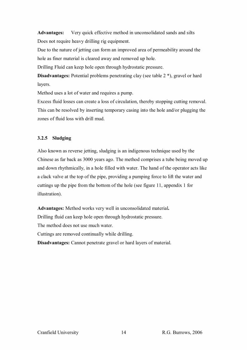
3.3.1 Vonder Rig: Developed by the Blair Institute in Zimbabwe, the Vonder rig is a large hand operated
auger suspended on a tripod and designed with a handle of sufficient size to allow a
number of people access to help input rotational force. Equipment costs around $600
US - average depth of borehole 10-15m (max depth being 35m).
Cost of each borehole was $150 US (Wurzel, 2001).
Photo 1: High participation is required to work the Vonder rig in the Lower Tana River area, Kenya. (Kenya water for health organisation website, 2006)
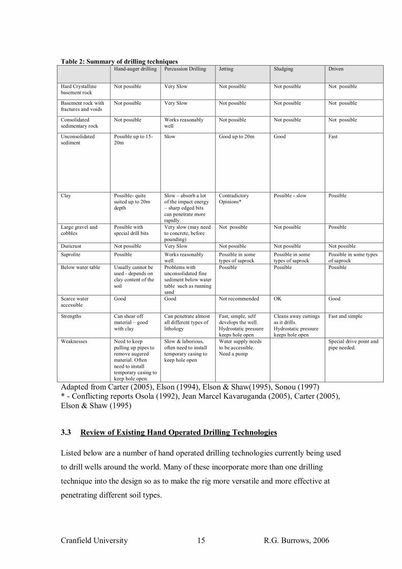
3.3.2 Emas Rig Emas has installed over 10,000 wells in South America.
The rig uses a combination of percussive, augering and jetting techniques to penetrate
the subsurface, although it can be adapted to sludging as well (Emas, 2006). Water is
jetted down a hollow drill pipe to the bit. The bit is used percussively through vertical
movement of the pipe and simultaneously it is rotated to aid in the break up of the
soil. The fluid jetted down the pipe, is released under pressure out of holes in the bit,
clearing material from the bit. This water then flows back up the hole carrying
material to the surface.
The pipe is supported with a rope passing over a pulley on the rig tower.
Cranfield University R.G. Burrows, 2006 17
Photo 2: The Emas drill bit (Buddhistische Haus , 2005)
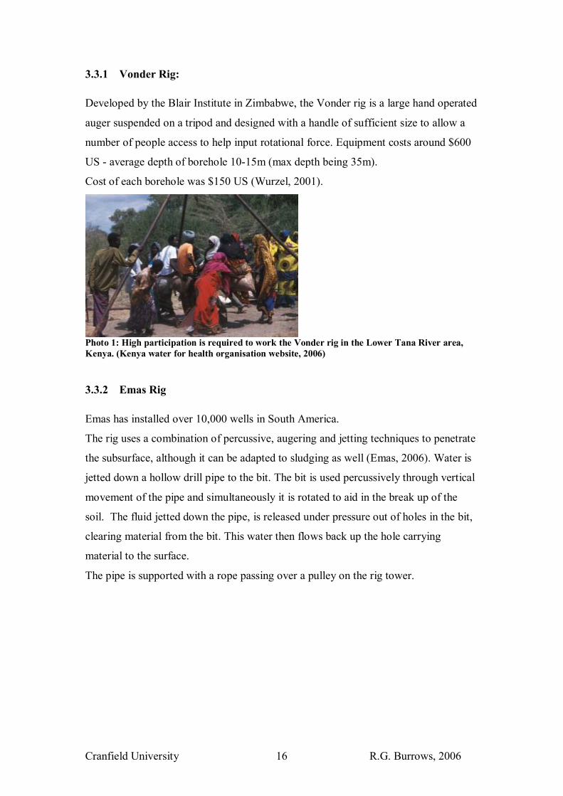
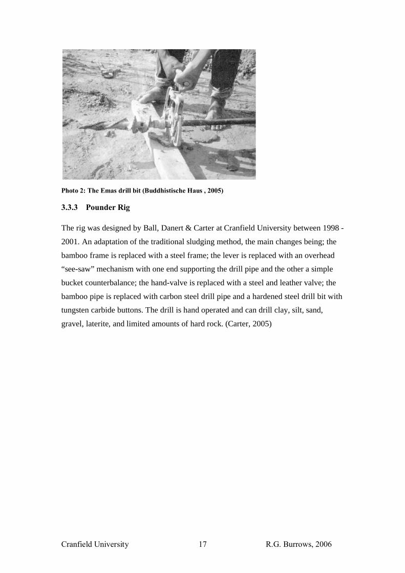
3.3.3 Pounder Rig The rig was designed by Ball, Danert & Carter at Cranfield University between 1998 -
2001. An adaptation of the traditional sludging method, the main changes being; the
bamboo frame is replaced with a steel frame; the lever is replaced with an overhead
“see-saw” mechanism with one end supporting the drill pipe and the other a simple
bucket counterbalance; the hand-valve is replaced with a steel and leather valve; the
bamboo pipe is replaced with carbon steel drill pipe and a hardened steel drill bit with
tungsten carbide buttons. The drill is hand operated and can drill clay, silt, sand,
gravel, laterite, and limited amounts of hard rock. (Carter, 2005)

Cranfield University R.G. Burrows, 2006 18
Photo 3: The Pounder Rig, taken at Cranfield University, Silsoe, 28/06/06
For more information on the Pounder Rig design please see the reports by Ball and
Carter (2000) and Carter (2001) describe the Pounder rig and the wider Pounder
project concept.
3.3.4 The Rota-sludge Rig This method was developed in 2000 in Nicaragua by the NGO CESADE
A modification of the Indian hand sludge method; using an arm and handle attached
to the drilling pipe the drill operator turns the pipe and hardened drill bit 90 degrees
on the bottom of every down stroke. The drilling pipe is then raised by means of the
bamboo lever and the drilling pipe is rotated back to its original position,
simultaneously the driller seals off the top of the pipe using his hand creating a
pumping action.
To make the rotation action more effective the drill bit has teeth which help to scrape
the bottom of the hole.
It was found that the Rota-sludge method has advantages over traditional sludging
methods in lithologies which had undergone greater compaction and cementation,
Cranfield University R.G. Burrows, 2006 19
causing the material to be more cohesive so difficult to break up eg. Sandstone, tuff
stone, compact sand/clay layers (Van Herwijnen & Roy, 2002).
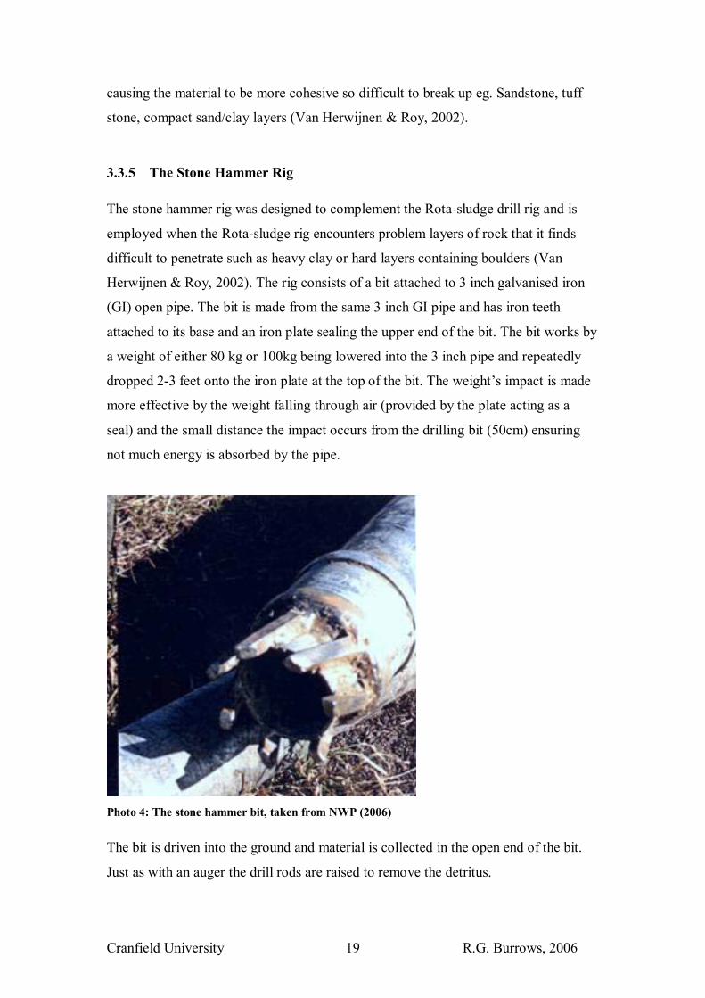
3.3.5 The Stone Hammer Rig The stone hammer rig was designed to complement the Rota-sludge drill rig and is
employed when the Rota-sludge rig encounters problem layers of rock that it finds
difficult to penetrate such as heavy clay or hard layers containing boulders (Van
Herwijnen & Roy, 2002). The rig consists of a bit attached to 3 inch galvanised iron
(GI) open pipe. The bit is made from the same 3 inch GI pipe and has iron teeth
attached to its base and an iron plate sealing the upper end of the bit. The bit works by
a weight of either 80 kg or 100kg being lowered into the 3 inch pipe and repeatedly
dropped 2-3 feet onto the iron plate at the top of the bit. The weight�s impact is made
more effective by the weight falling through air (provided by the plate acting as a
seal) and the small distance the impact occurs from the drilling bit (50cm) ensuring
not much energy is absorbed by the pipe.
Photo 4: The stone hammer bit, taken from NWP (2006)
The bit is driven into the ground and material is collected in the open end of the bit.
Just as with an auger the drill rods are raised to remove the detritus.

Cranfield University R.G. Burrows, 2006 20
The investment cost for a complete set of Rota-sludge or Stone-hammer equipment is
in the order of $800 in Africa and Latin America and about $100 in India. (NWP,
2006)
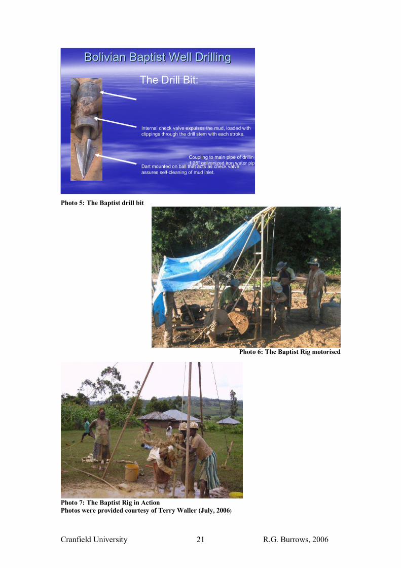
3.3.6 The Baptist Rig (Much of the following information is courtesy of Terry Waller, Southland B.C. Community development missionary and project director for the NGO �Water for All: Agua para todos) A hydraulic percussion rig, the Baptist rig consists of a combination of steel and
plastic hollow pipe attached to a ball and dart drilling point (see photo 5).
As the drill pipe and bit are repeatedly moved up and down the drill point acts as a
bottom check valve. On the down stroke the drill point strikes the bottom of the hole
and pushes the valve open, jetting cuttings up through the valve. On the up stroke the
valve closes and acts like a pump lifting the fluid column and bored material up the
pipe to be deposited at the surface. The drill rig can be adapted to run on a motor (see
photo 6).
Normal drilling rates in Bolivia and Kenya through tropical weathered lateritic
metamorphic rock is 2-3meters per day. In hard clays the same rig can drill around
20metres per day and in softer sediment up to 40metres per day.
In Bolivia, depending on the depth required, the cost of constructing a well with hand
pump can range between $50 and $100. (Henson, 2004)
About 2000 wells have been drilled with this technology, by Water For All trained
drillers or family groups (drilling clubs).
Cranfield University R.G. Burrows, 2006 21
Bolivian Baptist Well DrillingBolivian Baptist Well Drilling
Coupling to main pipe of drilling1.25� galvanized iron water pip
Internal check valve expulses the mud, loaded with clippings through the drill stem with each stroke.
Dart mounted on ball that acts as check valve assures self-cleaning of mud inlet.
The Drill Bit:
Photo 5: The Baptist drill bit
Photo 6: The Baptist Rig motorised
Photo 7: The Baptist Rig in Action Photos were provided courtesy of Terry Waller (July, 2006)
Cranfield University R.G. Burrows, 2006 22
4 Technology Selection / Design Criteria
4.1 Introduction
In choosing equipment and materials for the design rig, certain factors/elements
needed to be considered in order to ensure that the rig will be successfully adopted by
the local small scale private sector.
4.2 The effectiveness of the equipment :
4.2.1 Drilling speed The quicker the well is constructed, the cheaper the overall well costs, the more
profitable it will be for the drilling contractor (providing that they have work lined up)
and the more wells it will be possible to sink in a shorter period of time.
Capacity: Percussion drilling and augering require the drill pipes or cable/rope to be
pulled up so as to remove the detritus at the bottom of the hole, this is time consuming
and requires a lot of effort. Jetting, driving and sludging utilise much quicker methods
of removing material, through either circulation of fluid or in the case of driving,
pushing the material to the sides of the hole.
Recommendations: The drill rig should be designed so as to have a means of
removing material simultaneously to boring, this would enhance the effectiveness of
the rig design.
4.2.2 Ability to penetrate different lithologies The rig should be adaptable and be able to penetrate variable soils. This will enable it
to access more localities. It will also allow people greater choice as to where to locate
the wells resulting in the water supply being more convenient to those it is built to
serve. This will also lead to fewer failed drilling attempts.
Capacity: Jetting and sludging work well through unconsolidated sediments,
augering works well in clay and percussive drilling is most appropriate when harder
material is encountered, although slow.
Recommendations: Hard rock condition should be avoided by appropriate siting of
the borehole whenever possible.

Cranfield University R.G. Burrows, 2006 23
The drill rig should have a sludging or jetting capability, a rotary capability to shear
through clay and a percussive capability for when harder rock is encountered.
4.2.3 Maximum Depth The deeper the well can be built, the more water that can be accessed.
Capacity: This is very dependent on the maximum weight of drill pipe that can be
lifted and the type of ground conditions that the drill rig encounters.
Recommendations: Maximum depth is often constrained by the amount of weight
the operators can lift. Making the drill pipe as light as possible would be
advantageous.
4.2.4 Hole Diameter Due to the nature of a cylinder (Πr²h) the hole diameter has a huge influence on how
much material is drilled through. For example the surface area of a 4� diameter hole is
close to half that of a 6� diameter hole. The flow of water into a well, if calculated
using Dupuit�s formula, is on the contrary not greatly affected by borehole diameter
size.
Capacity: It is possible to install handpumps into 3� diameter wells (Cansdale, 2006).
Recommendations: The kit should drill holes to a diameter of between 100mm-
120mm. This will enable 3 inch casing to be accommodated inside the hole with room
for a gravel pack or a geotextile filter.
4.2.5 Hole Straightness The hole needs to be straight so as to fit the permanent casing, well screen and pump
without difficulty.
Recommendations: This can be achieved by using stabilisers attached to the drill
pipe; by using a tripod to allow the pipe to hang vertical; by using a supportive clamp
on the ground, supporting the entrance of the hole; by using steel sections of pipe to
act as a rigid weight at the bottom of the pipe.

Cranfield University R.G. Burrows, 2006 24
4.3 The availability of resources
4.3.1 Financial Capital It is assumed a limited amount of start up capital is available to the entrepreneur,
therefore the cheaper the components that make up the drill, the better.
Recommendations: Use only local resources to construct the rig
4.3.2 Social Capital Government support legislation, demand for clean water, the strength of the private
sector, the strength of local community groups, will not affect rig design, but will
make a difference to whether the technology is successfully adopted.
4.3.3 Skills There is a lack of specialized technical and business skills in many parts of Sub-
Saharan Africa (Ball, 2004).
Skills assumed to be locally available: Mechanics, metal workers, carpenters, manual
labour.
Recommendations: The simpler and cheaper the technology, the easier the
technology can be maintained, managed and made profitable and the easier it will be
for local men and women to cope with running the business successfully.
4.3.4 Materials Plastic pipe, steel pipe, mud pumps, tripods, wood, leather, grease and basic tools all
are assumed to be available in country.
Local materials such as nut, cow dung or clay could be used to create drilling muds.
Jose (1988) found potato starch creates a good viscous solution.
Recommendations: Design and construct the rig using locally available material
4.3.5 Energy All the drilling techniques need to deliver energy to the soil or rock to penetrate
through breaking, loosening, pulverising the material. They also need energy to
transport this crushed material to surface.
The following energy generating systems were considered:
• Petrol/Diesel combustion engine - require maintenance, fuel and oil.

Cranfield University R.G. Burrows, 2006 25
• Electricity � many towns and remote locations will have no electricity supply.
Some electric pumps however could be run off a car battery or engine.
• Wind � variable wind conditions make this type of energy supply unreliable.
• Solar power � expensive
• Man power � always readily available, very limited as to the amount of power
output per person.
Recommendations: To use man power foremost to power the rig and to use a one
cylinder petrol engine to drive a mud pump.
4.3.6 Water May or may not be locally available, to transport it would be costly.
Recommendations: The drill rig will need to be able to work effectively in areas
without much water availability.
4.3.7 Transport Vehicle transport may be quite limited. Mules, oxen or horses are used as an
alternative form.
Recommendations: The rig should be designed to be as light and as portable as
possible
4.4 Cost per well
Costs can be broken down into three different types:
• The initial capital cost of the equipment: Includes import tax and shipping
costs for overseas equipment.
• The Running costs: Includes well consumables costs, maintenance costs and
labour costs.
• Overhead costs: The provision of capital, administration, and logistics
Start up capital will require individuals to borrow money, though this will limit future
profits due to interest repayments. Small operations and small loans should keep
overhead costs to a minimum and encourage small businesses to venture into the
market.
Cranfield University R.G. Burrows, 2006 26
Recommendations: Costs should be kept to a minimum. Using local resources and
materials would decrease substantially capital cost and running costs.
4.5 The replicability of the technology
The simplicity of the rig, the ease of making and operating the rig and the
compatibility of the rig to the regions existing ideas and experiences are all factors
which will determine the capacity of the drill rig to be replicated (Rogers, 2003). See
also Danert (2002) for more information on technology transfer. Having the same
technology operating throughout an area would enhance the sustainability of the
technology as it would encourage the growth of supply chains and knowledge and
skill as to how to utilise the equipment.
Recommendations: Make the technology as simple and adaptable as possible using
as much local technological ideas and practices as possible.
Cranfield University R.G. Burrows, 2006 27
5 The Rig Design
The rig was formulated by combining four of the five existing hand operated drilling
techniques into one piece of kit.
The four techniques chosen were percussion, augering, jetting and sludging. They
were incorporated into the design rig because of certain individual characteristics:
• Percussion - because it is the most effective means to break through harder
material.
• Augering (or using a rotary action) - because it is an effective means to shear
through clay material.
• Jetting - for its ability to drill very rapidly through unconsolidated material, to
clear cuttings from the bottom of the hole through circulation of fluid, to keep
a borehole open without casing through hydrostatic pressure.
• Sludging � To be used when jetting is not an option due to unavailability of a
mud pump or inadequate access to sufficient water.
The driving technique was not included in the rig design due to its requirement for
specialist drill casing and drive point. The drive point and casing would not have been
easily adaptable to other hand operated techniques and would be potentially more
expensive to obtain.
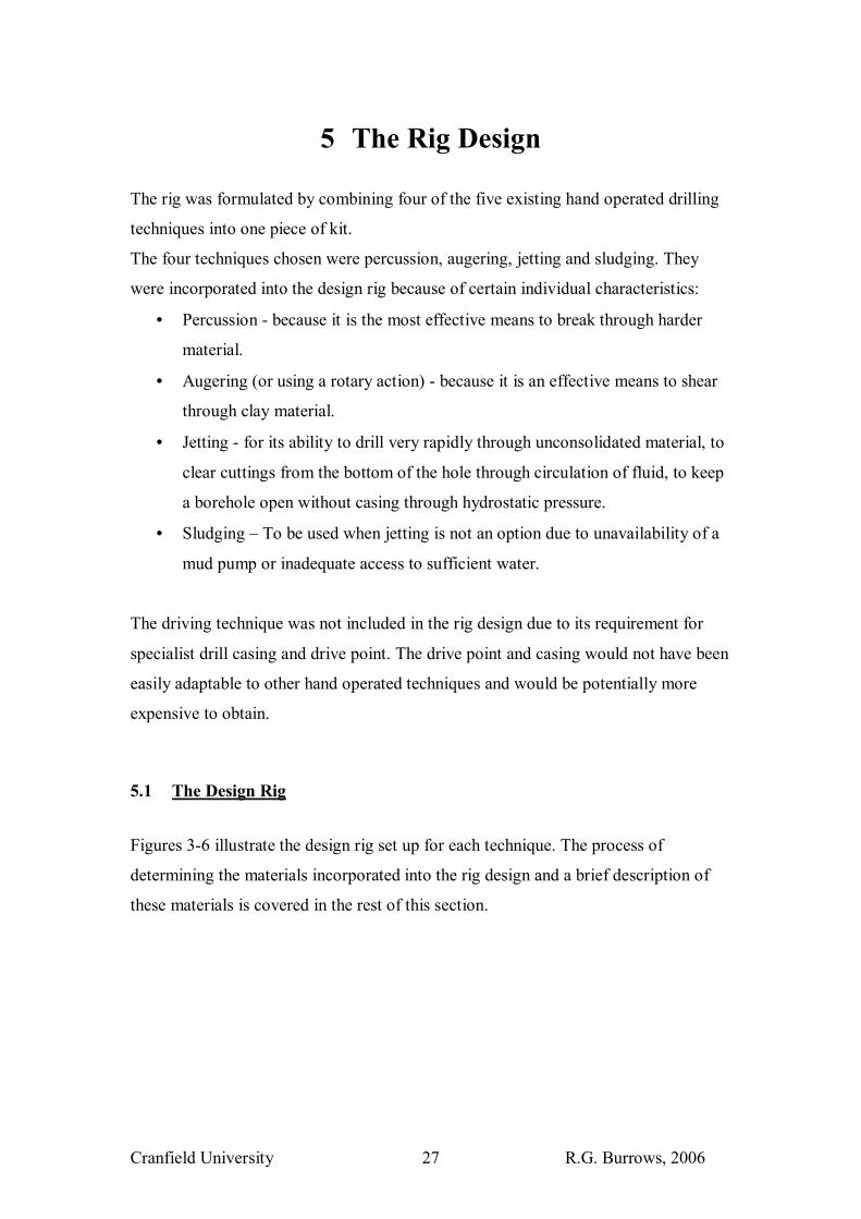
5.1 The Design Rig
Figures 3-6 illustrate the design rig set up for each technique. The process of
determining the materials incorporated into the rig design and a brief description of
these materials is covered in the rest of this section.
Cranfield University R.G. Burrows, 2006 28
Figure 3: The rig - set up for jetting
Figure 3: The rig - set up for jetting
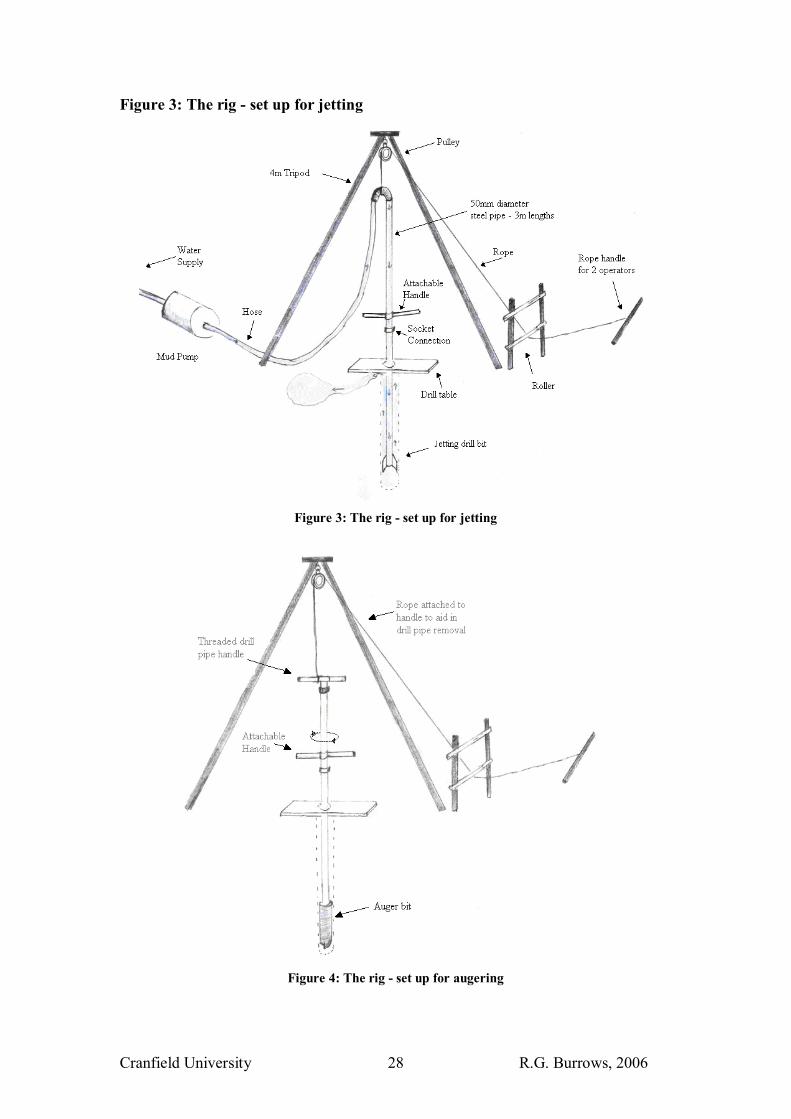
Figure 4: The rig - set up for augering
Cranfield University R.G. Burrows, 2006 29
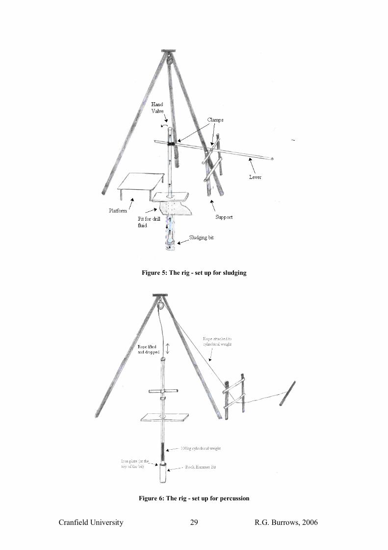
Figure 5: The rig - set up for sludging
Figure 6: The rig - set up for percussion

Cranfield University R.G. Burrows, 2006 30
5.2 The Materials Inventory
To aid the combining of the different drilling techniques into one rig, a materials
inventory was fabricated. The inventory lists the various composite materials of each
individual drill technique. This materials inventory is illustrated in table 3. Table 3: Materials Inventory
Percussion Augering Sludging Jetting
Driving
Drill Rig surface
structure
Tripod Tripod Tripod Tripod Tripod
Handle for rope /
Winch
Handle for rope to lift
auger
Lever Handle for rope Winch
Handle to attach to
drill pipe
Ladder or platform for
hand sludging
Rope/cable Rope/cable Rope/cable
Peg to tie off rope Peg to tie off rope
block/pulley Pulley or block Pulley or block Pulley or block
Roller Hose Hammer
Hose attachment
Possible pit lining Recycling water �
strainer or liner for
settling pit
water storage device eg
a bowser
Valve or hand Pump Steel hammer
shield
Clamps Clamps Clamps Clamps Clamps
Cable or drill pipe Drill rod or drill pipe Drill pipe Drill Pipe
Tools Hand auger Hand auger Hand auger
Shovel Shovel Shovel Shovel
Stilsons Stilsons Stilsons Stilsons Stilsons
Wire brush + grease Wire brush + grease Wire brush + grease Wire brush + grease
Rags to protect drill
threads
Rags to protect drill
threads
Rags to protect drill
threads
Rags to protect drill
threads
For Drill stem Cutting bit and bailer Auger bit Drill bit Driving point
Temporary steel
casing
Temporary steel
Casing
Temporary Plastic
Casing
Temporary Plastic
Casing
Winch
Weight attachment Weight attachment Weight attachment Weight attachment Weight
attachment
Little bit of water Little bit of water Some water �at least 3
times EOH borehole
volume
Good supply of water
For Well Pump Pump Pump Pump Pump
Permanent Casing Permanent Casing Permanent Casing Permanent Casing Permanent steel
Cranfield University R.G. Burrows, 2006 31
casing
Well Screen Well Screen Well Screen Well Screen Permanent steel
well screen
Gravel Pack Gravel Pack Gravel Pack Gravel Pack
Cement Cement Cement Cement Cement
Bentonite Sanitary
seal
Bentonite sanitary
seal
Bentonite sanitary seal Bentonite sanitary seal
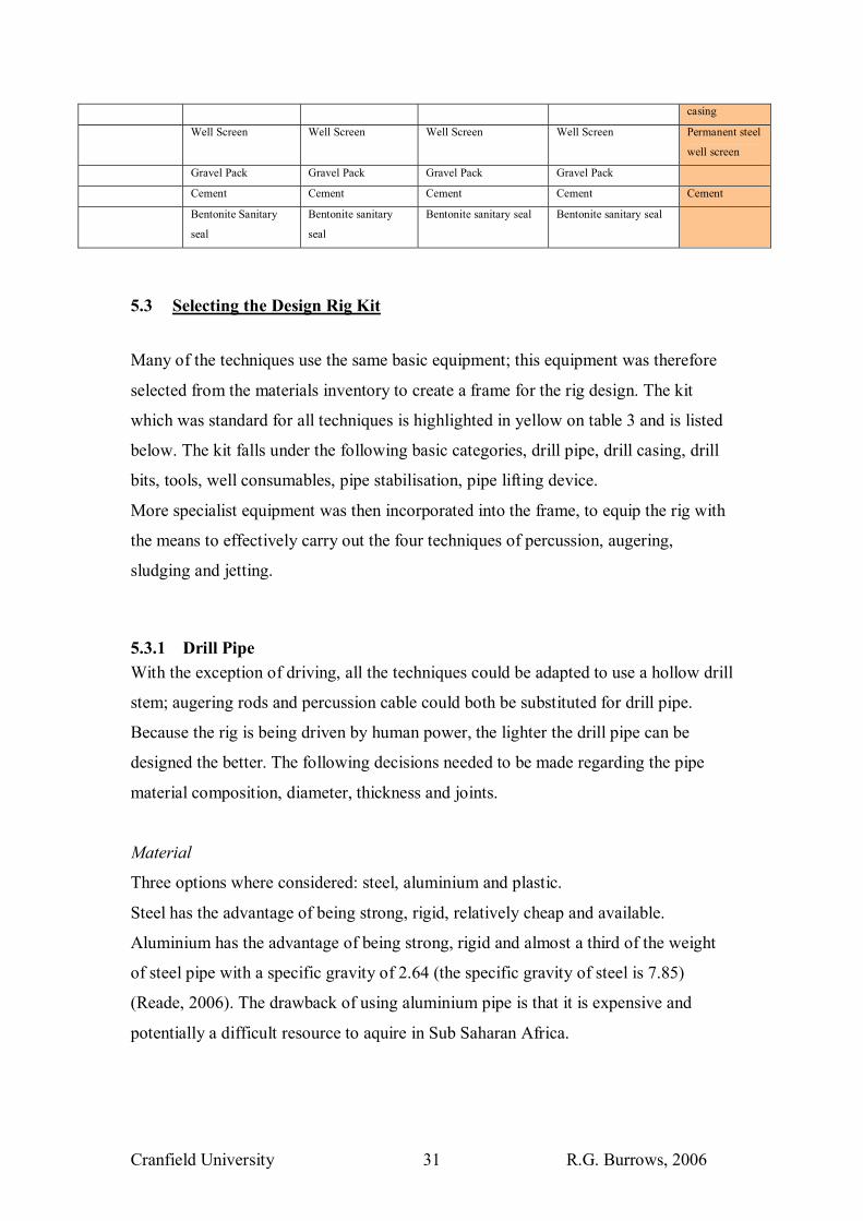
5.3 Selecting the Design Rig Kit
Many of the techniques use the same basic equipment; this equipment was therefore
selected from the materials inventory to create a frame for the rig design. The kit
which was standard for all techniques is highlighted in yellow on table 3 and is listed
below. The kit falls under the following basic categories, drill pipe, drill casing, drill
bits, tools, well consumables, pipe stabilisation, pipe lifting device.
More specialist equipment was then incorporated into the frame, to equip the rig with
the means to effectively carry out the four techniques of percussion, augering,
sludging and jetting.
5.3.1 Drill Pipe With the exception of driving, all the techniques could be adapted to use a hollow drill
stem; augering rods and percussion cable could both be substituted for drill pipe.
Because the rig is being driven by human power, the lighter the drill pipe can be
designed the better. The following decisions needed to be made regarding the pipe
material composition, diameter, thickness and joints.
Material
Three options where considered: steel, aluminium and plastic.
Steel has the advantage of being strong, rigid, relatively cheap and available.
Aluminium has the advantage of being strong, rigid and almost a third of the weight
of steel pipe with a specific gravity of 2.64 (the specific gravity of steel is 7.85)
(Reade, 2006). The drawback of using aluminium pipe is that it is expensive and
potentially a difficult resource to aquire in Sub Saharan Africa.

Cranfield University R.G. Burrows, 2006 32
Plastic pipe is cheap and lightweight, however it is flexible (a problem for obtaining
hole straightness) and also not as strong as aluminium and steel, especially in regards
to torque.
Recommendation: The rig will be required to provide rotary action to the bit,
therefore steel pipe was considered to be the best option.
Drill Pipe Diameter
The diameter of the drill pipe has a direct consequence on the weight of the pipe.
Both jetting and sludging require a minimum diameter pipe to perform adequately.
In jetting, pipe diameter also determines the final hole diameter.
Kavaruganda (2005) found when jetting in sand, that final hole diameter was
regulated by pipe diameter and discharge. Past experiments have shown that when
using 50mmØ jetting equipment final hole diameters of 100-150mm have been
achieved created by the erosion of the upflowing water (Kavaruganda, 2005). This
upflowing water reaches a natural equilibrium point where the hole diameter is of
sufficient size to reduce the upflowing water below erosional speed.
Sludging efficiency depends also on pipe diameter. Wardle (1999) found that a higher
discharge rate facilitates penetration when sludging. By employing a larger diameter
drill pipe the rate of flow will be greater and the chances of cuttings blocking the pipe
will be less.
Recommendation: An end hole diameter of between 100-120mm is required.
Following Kavarunganda�s observations that 50mmØ pipe can produce a 100-
150mmØ borehole in sand, it is assumed that by using this size diameter pipe and a
100mm diameter bit, a minimum hole diameter of 100mm would be created in any
material whilst the uphole velocity of drill fluid would be sufficient to carry material
to the surface. It is important to calculate up flow velocity and set discharge rate
accordingly. Sinking velocity of coarse sand is around 0.15m/s (Clark 1988) and Ball,
2006 recommends a minimum of 30m/min uphole velocity.
Thickness
The thinner the pipe walls, the lighter the pipe.
Bell (1984) used steel pipe with wall thickness of 1.65mm which weighed roughly
2.6kg per metre, however this pipe needed additional support installed at the wall
attachments � this complicates the technology.

Cranfield University R.G. Burrows, 2006 33
Recommendations: Pipe wall thickness should be kept between 3-5mm, so as to
keep the pipe light (around 4kg/metre) simple and strong.
Type of pipe connection:
Two types of pipe connections were considered flush joint or external socket.
Flush joints do not interfere with fluid circulation, external sockets on the other hand
are much easier and cheaper to craft using a tool such as the Virex Threading
Machine.
Recommendation: To use external socket connections on the pipe.
To divide the pipe into 3m lengths so as to minimise the time spent adding and
removing pipe.
To use some oily rags as end caps so to protect the drill pipe threads during
transportation.
5.3.2 Tools The following tools would be needed to work the drill: Spanner, screwdriver, wire
brush, grease, stilsons, shovel, auger and a mallet.
5.3.3 Drill pipe stabilisation To keep the borehole straight and perpendicular to the ground it is necessary to keep
the drill pipe vertical and steady, the following items facilitate this:
• Tripod: Suspends the drill pipe vertically by means of a rope and pulley. To be at
least 4m high to take comfortably 3m of drill pipe
• Drilling Table: To hold drill pipe steady in the hole.
5.3.4 Drill pipe lifting device • Rope or cable: A cable is stronger than a rope, however because this is a human
powered rig a good quality rope should be sufficient for the tension that it will be
required to handle, it is also lighter, easier to roll, knot and better on the hands.
• Pulley: Attached to the top of the tripod. The pulley allows the rope easy
movement without causing significant friction as the pipe is pulled and dropped.

Cranfield University R.G. Burrows, 2006 34
• Rope Handle: Comprising a bar or strong branch, attached to the rope which is
slung through the pulley. Allows the operators a good, comfortable grip on the
rope as they pull on the drill pipe.
• Roller: Comprising two pipes, one of slightly greater diameter than the other and
some grease between the two. Fixed to two supporting legs near the bottom of the
tripod. The rope will be pulled via the roller to allow the operators to pull in a
more horizontal direction affording them the use of their legs
• Two large handles: Can clamp on to the drill pipe (as in Bell�s design, 1984). The
handles will be used to help lift the drill pipe, to give an operator a tool to provide
rotary action to the pipes, to help detach threads + hold drill pipe in ground. An
operator can also stand on the handles straddling the pipe to provide extra weight
(Bell, 1984). These handles could also be used as a tool to aid in knocking down
casing, by using the weight of drill pipe as a downward force.
5.3.5 Temporary Casing Temporary casing would be used in circumstances of borehole collapse (running
sand) or problems with fluid circulation (very permeable material or fractures). The
casing would be inserted into the hole behind the bit when required.
Recommendations:
Three options were considered, steel, aluminium and plastic. Plastic was thought most
suitable, being light and cheap and unlike the drill pipe it would not be required to
take very large forces or any torque.
Temporary Casing steel cutting edge - to help the casing gain access into the hole
Temporary Casing steel hammer ring - for the hammering down of the casing if
necessary
5.3.6 Well Consumables The following materials are required to install the well after the borehole has been
completed: 3� permanent casing and well screen, gravel pack, bentonite, cement,
geotextile cloth, pit liner, mud pump or plunger to help develop the well, hand pump.
Cranfield University R.G. Burrows, 2006 35
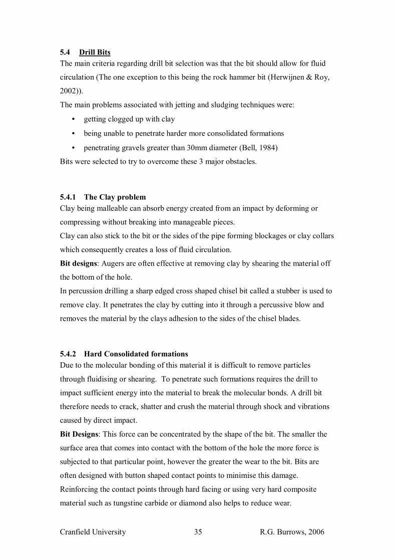
5.4 Drill Bits The main criteria regarding drill bit selection was that the bit should allow for fluid
circulation (The one exception to this being the rock hammer bit (Herwijnen & Roy,
2002)).
The main problems associated with jetting and sludging techniques were:
• getting clogged up with clay
• being unable to penetrate harder more consolidated formations
• penetrating gravels greater than 30mm diameter (Bell, 1984)
Bits were selected to try to overcome these 3 major obstacles.
5.4.1 The Clay problem Clay being malleable can absorb energy created from an impact by deforming or
compressing without breaking into manageable pieces.
Clay can also stick to the bit or the sides of the pipe forming blockages or clay collars
which consequently creates a loss of fluid circulation.
Bit designs: Augers are often effective at removing clay by shearing the material off
the bottom of the hole.
In percussion drilling a sharp edged cross shaped chisel bit called a stubber is used to
remove clay. It penetrates the clay by cutting into it through a percussive blow and
removes the material by the clays adhesion to the sides of the chisel blades.
5.4.2 Hard Consolidated formations Due to the molecular bonding of this material it is difficult to remove particles
through fluidising or shearing. To penetrate such formations requires the drill to
impact sufficient energy into the material to break the molecular bonds. A drill bit
therefore needs to crack, shatter and crush the material through shock and vibrations
caused by direct impact.
Bit Designs: This force can be concentrated by the shape of the bit. The smaller the
surface area that comes into contact with the bottom of the hole the more force is
subjected to that particular point, however the greater the wear to the bit. Bits are
often designed with button shaped contact points to minimise this damage.
Reinforcing the contact points through hard facing or using very hard composite
material such as tungstine carbide or diamond also helps to reduce wear.

Cranfield University R.G. Burrows, 2006 36
For good drilling rates it is advantageous to continually change the point at which the
force impacts on the bottom of the hole, so that all the rock is broken up and the weak
fractures are exploited.
Once crushed into transportable size pieces the material can then be removed from the
hole in suspension via the drilling fluid.
5.4.3 Gravels Bell, H. (1984) reported problems with jetting when encountering gravels in the
Lower Sussex Ouse River Valley. He found that the gravels were too heavy to be
removed all the way up the hole and that they resettled at the bottom of the hole once
the jet pump had been switched off, trapping the jetting pipe in the hole, making the
removal of the drill pipe difficult or even impossible.� (Bell, 1984)
This problem can be minimised by either:
• Installing casing into the hole and increasing the discharge of water to improve
uphole velocity.
• Increasing the viscosity of the drill fluid using an additive such as clay, the
fluid can hold the gravel in suspension for a greater length of time and
consequently transport more material to the surface.
• Or Marumo (1987) found that a bit which angled jets of water up-hole could
remove more gravel than a bit which angled its jets downhole.
5.4.4 Drill Bit Design Jetting in clay was identified as a problem in the literature review. Two bits were
designed to try and facilitate jetting when encountering clay material and hard bands
of more consolidated rock.
The cross chisel bit (design 1, appendices 6)
This bit was designed to imitate the percussion rig stubber, with the exception that 4
inlets in the bit let water in and out of the drill stem. The reduction of area at the inlets
would increase the jetting water velocity and remove material that became stuck to
the chisels sides.

Cranfield University R.G. Burrows, 2006 37
When sludging, the cross shaped chisel would protect the inlets from coming into
contact with the bottom of the hole and becoming clogged up and instead would suck
material into the annulus at every down stroke.
The chisels would aid penetration and soil disturbance through a percussive force.
The bit was designed to create holes of a minimum of 100mm diameter.
Stabilisers were attached to ensure the hole was kept straight and clear (design 2,
appendices 6).
Photo 8: The cross chisel bit
The dart valve bit (design 3, appendices 6)
Adapted from the principles of the Baptist rig drill bit, the main idea was to
incorporate a moving part at bottom of drill pipe to keep clay from clogging up the
pipe inlet.
The bit worked by the use of a check valve attached to a dart point. When jetting, the
water pressure would cause the check valve to shut and water would be forced out of
the holes drilled into the side of the pipe, clearing debris from the sides of the bit. As
soon as the dart made contact with the bottom of the hole however the check valve
would be opened and water would blast out of the bottom as the bit was ground
against the end of the hole.
The outer fins of the drill bit were designed to auger material.
The bit was designed to create holes of a minimum of 100mm diameter

Cranfield University R.G. Burrows, 2006 38
Photo 9: The dart valve bit
5.5 Specialist Equipment
More specialist equipment was incorporated into the kit so as to equip the design rig
with the means to effectively carry out the four techniques of percussion, augering,
sludging and jetting.
Jetting specialist equipment
• Need a hose
• A hose attachment to pipe
• A pump: either a farmers mud pump or a man powered treadle pump
• A water storage device such as a bowser or close by surface water
• A strainer
For Sludging
• Need a valve: or a hand
• A lever: allowing operators to have a good control of the pipe and timing
between each stroke.
• Rope or clamp: to attach lever to pipe

Cranfield University R.G. Burrows, 2006 39
• Platform: To allow operator access of top of drill pipe � to attach hose or use
his hand as a valve during sludging.
For Percussion
• Need a 100kg cylindrical weight with an OD (outer diameter) smaller than the
ID (internal diameter) of the drill pipe.
• A rope to hold on to the weight
• A �rock hammer� type bit (Practica foundation, 2006)
For Augering �
• An auger bit
• A handle attached to the drill pipe to turn the bit
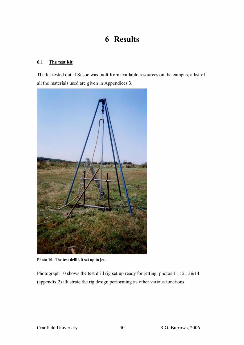
Cranfield University R.G. Burrows, 2006 40
6 Results 6.1 The test kit The kit tested out at Silsoe was built from available resources on the campus, a list of
all the materials used are given in Appendices 3.
Photo 10: The test drill kit set up to jet.
Photograph 10 shows the test drill rig set up ready for jetting, photos 11,12,13&14
(appendix 2) illustrate the rig design performing its other various functions.
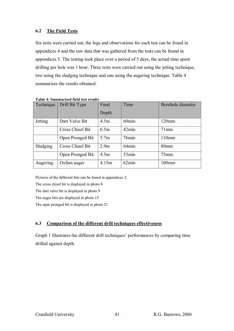
Cranfield University R.G. Burrows, 2006 41
6.2 The Field Tests Six tests were carried out, the logs and observations for each test can be found in
appendices 4 and the raw data that was gathered from the tests can be found in
appendices 5. The testing took place over a period of 5 days, the actual time spent
drilling per hole was 1 hour. Three tests were carried out using the jetting technique,
two using the sludging technique and one using the augering technique. Table 4
summarises the results obtained.
Table 4: Summarised field test results Technique Drill Bit Type Final
Depth
Time Borehole diameter
Jetting Dart Valve Bit 4.5m 60min 120mm
Cross Chisel Bit 6.5m 42min 71mm
Open Pronged Bit 5.7m 76min 110mm
Sludging Cross Chisel Bit 2.9m 64min 80mm
Open Pronged Bit 4.5m 53min 75mm
Augering Oxfam auger 4.15m 62min 100mm
Pictures of the different bits can be found in appendices 2.
The cross chisel bit is displayed in photo 8
The dart valve bit is displayed in photo 9
The auger bits are displayed in photo 15
The open pronged bit is displayed in photo 21
6.3 Comparison of the different drill techniques effectiveness Graph 1 illustrates the different drill techniques� performances by comparing time
drilled against depth.

Cranfield University R.G. Burrows, 2006 42
Comparison of drill techniques
00.5
11.5
22.5
33.5
44.5
55.5
66.5
77.5
88.5
99.510
1 6 11 16 21 26 31 36 41 46 51 56 61
Time (min)
Dep
th (m
)
Cross Chisel Jetting
Open Pronged Jetting
Dart Valve Jetting
Cross Chisel Sludging
Open Pronged Sludging
Augering
Linear (Open Pronged Jetting)
Linear (Cross Chisel Jetting)
Linear (Cross Chisel Sludging)
Graph 1: Comparison of drill techniques
The graph shows that open pronged jetting was the quickest method out of those that
were tested drilling at an average rate of 7min/m. This was 4 times faster than the
cross chisel sludging which averaged 30min/m and twice as fast as all the other
techniques which came up with similar rates of penetration averaging around 14
min/m.
The cross chisel bit and open pronged bit were used to directly compare jetting with
sludging. The graph also demonstrates that when the bits were used for jetting they
drilled at double the speed to when they were used for sludging.
Soil samples were analysed using the Buoyoucos method and sieve analysis to
provide information about the composition and texture of the soil the rigs drilled
through (see appendices 5 for raw data). Figure 12, appendices 5 shows how these
different samples were classified into soil groups using the ISSS (International
Society of Soil Science) soil textural classification.
Graph 2 compares the drilling rates of the different techniques against the differing
soil groups that were drilled through.

Cranfield University R.G. Burrows, 2006 43
Graph 2: Comparison of drill techniques effectiveness in differing lithologies
The graph shows that all the drill techniques had slower penetration rates when
negotiating through the sandy clay loam at around 3.5- 4.5m. Surprisingly jetting
using the open pronged bit appears to work better in the clay than in the sandy clay
loam and the sandy loam. This is probably due to these soils still having sufficient
clay in their matrix to prevent the material from fluidising. The open pronged bit
when sludging also shows a decrease in penetration rate between 3.5-4.5m, this is
possibly reflecting the loss of the bit, rather than just a decrease in performance as a
consequence of the lithology.
The results do not show any real advantages of any of the drilling techniques enjoying
over any of the other techniques in a particular soil type.
The tests each produced holes of different diameters. Graph 1 therefore gives a biased
picture, favouring the drill techniques which produced smaller diameter holes over
those bits which removed more material and produced larger diameter ones.
To compensate for this bias, material removed from the hole was calculated by
multiplying borehole depth with borehole diameter (table 7, appendices 5). This

Cranfield University R.G. Burrows, 2006 44
information was then recalculated into depth drilled using a standard borehole
diameter of 100mm as is illustrated by graph 3.
Comparing techniques by standardising borehole diameters to 100mm
0
1
2
3
4
5
6
7
0 4 8 12 16 20 24 28 32 36 40 44 48 52 56 60
Time (minutes)
Dep
th (m
)
Cross Chisel Jetting
Open Pronged Jetting
Dart Valve Jetting
Cross Chisel Sludging
Open Pronged Sludging
Augering
Graph 3: Comparing techniques by standardising borehole diameters to 100mm
This graph gives a fairer picture of the different techniques effectiveness at removing
material and penetrating the subsurface.
From this graph it is clear that sludging is the slowest drilling technique, with the
open pronged bit removing material at an average rate of 26min/m and the cross
chisel at 41min/m. Augering performs on a par with jetting with the pronged bit
removing material at an average rate of 17min/m. The two designed jetting bits
however are by far the most effective, removing material at an average rate of
10min/m.
It is also interesting to consider how the jetting technique relates to more conventional
modes of drilling. Graph 4 gives a very crude comparison of how cable percussion
and rotary drilling carried out during the CWS drilling week (see appendix 7 for drill
logs) performed in comparison with the hand operated drilling.
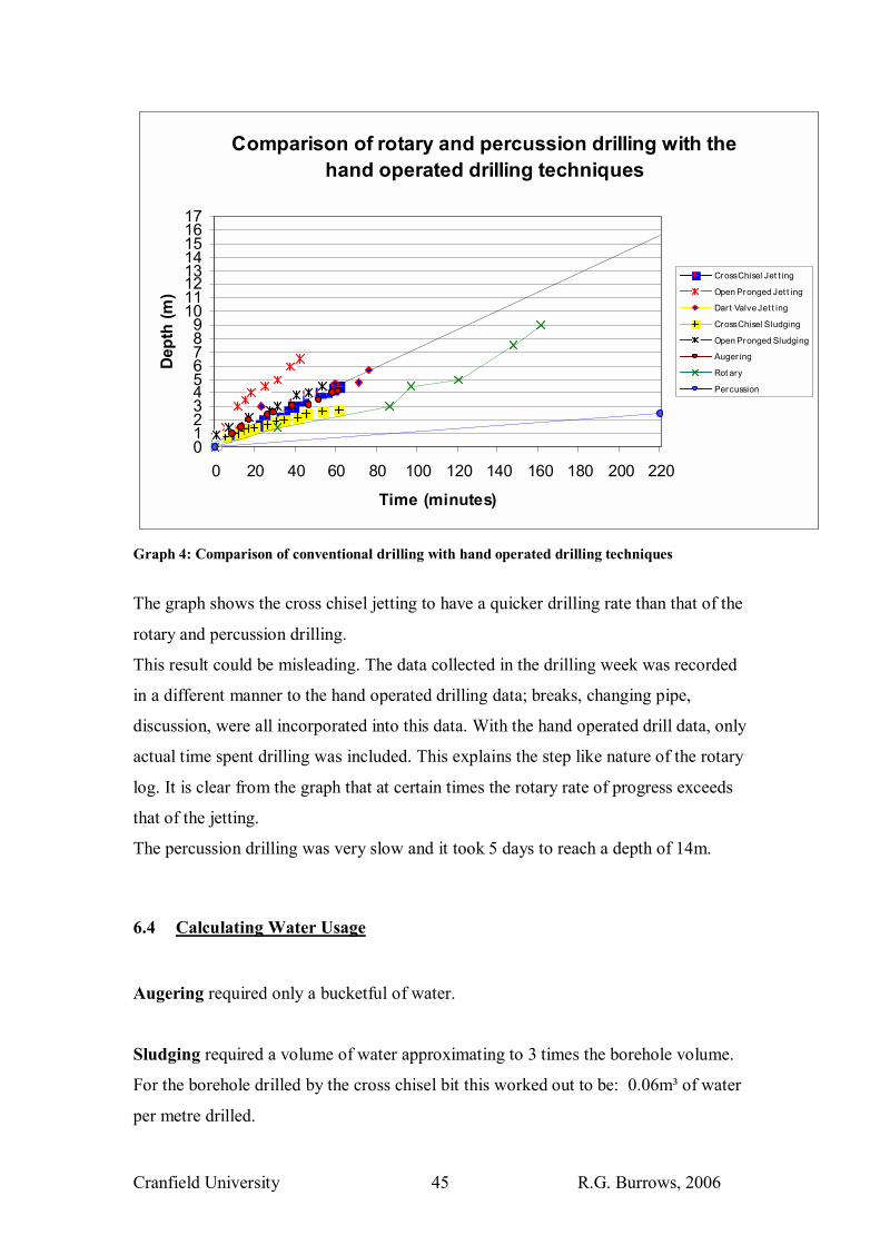
Cranfield University R.G. Burrows, 2006 45
Comparison of rotary and percussion drilling with the hand operated drilling techniques
0123456789
1011121314151617
0 20 40 60 80 100 120 140 160 180 200 220
Time (minutes)
Dep
th (m
)
Cross Chisel Jet t ing
Open Pronged Jet t ing
Dar t Valve Jet t ing
Cross Chisel Sludging
Open Pronged Sludging
Auger ing
Rot ary
Percussion
Graph 4: Comparison of conventional drilling with hand operated drilling techniques
The graph shows the cross chisel jetting to have a quicker drilling rate than that of the
rotary and percussion drilling.
This result could be misleading. The data collected in the drilling week was recorded
in a different manner to the hand operated drilling data; breaks, changing pipe,
discussion, were all incorporated into this data. With the hand operated drill data, only
actual time spent drilling was included. This explains the step like nature of the rotary
log. It is clear from the graph that at certain times the rotary rate of progress exceeds
that of the jetting.
The percussion drilling was very slow and it took 5 days to reach a depth of 14m.
6.4 Calculating Water Usage Augering required only a bucketful of water.
Sludging required a volume of water approximating to 3 times the borehole volume.
For the borehole drilled by the cross chisel bit this worked out to be: 0.06m³ of water
per metre drilled.

Cranfield University R.G. Burrows, 2006 46
Whilst the borehole drilled by the open pronged bit worked out to be: 0.05m³ of water
per metre drilled.
Jetting consumed by far the most water � the following quantities were calculated:
Dart Valve Bit
Water use: 28seconds to fill up a 100litre container
Therefore drilling for 76 minutes = 16.3m³ of water consumed to drill 5.7m
=2.9m³ per metre drilled
Cross Chisel Bit
Water Use: 23seconds to fill up a 100litre container
Therefore we drilled for 61 minutes = 15.9m³ of water consumed to drill 4.5m
=3.5m³ per metre drilled
Open Pronged Bit
Water use � not recorded due to the loss of the bit prior to the undertaking of the test
during sludging.
Jetting therefore used approximately 60 times more water than sludging.
It should be noted that this volume could be greatly reduced though recycling the
drilling fluid. This can be done through constructing a collection and storage ditch/pit.
Osola (1992) estimated that by recycling jetting water a 76% saving could be made in
water usage.
6.5 Calculating Maximum Depth Maximum depth is dependant on the amount of drill pipe the operators can
comfortably lift. If a man can pick up around 50kg and the rig design allowed for 2 �
3 men to be lifting the pipes at any one time, then the maximum weight that could be
supported would be between 100-150kg.
The equipment used for the test rig weighed the following:

Cranfield University R.G. Burrows, 2006 47
3m of steel pipe weighed 12kg - 1m of steel pipe = 4kg
Cross chisel bit + 1.5m length of pipe weighed 8kg
Valve bit + 1.5m length of pipe weighted 7kg
Jet connection piece weighed 1kg, 2kg with hose attached.
Therefore from the above weights it was calculated that 2 men could drill to a
maximum of 24m whilst 3 men could potentially drill to a depth of 36.5m.
6.6 Estimating cost Costs per well will vary from country to country depending on numerous factors
including resource availability and the countries economy. However as table 5
illustrates below if one uses costs of similar technologies as a comparitable measure
to estimate the design rig costs, it is unlikely that well costs will exceed $200 US and
they could be as little as $50 US. Table 5: Well & equipment costs Rig Type Equipment
costs.
Cost per well Reference
Rota Sludge $800-$100 NWP,2006
Stone Hammer $800 -$100 NWP,2006
Vonder Rig $600 $150 Wurzel, 2001
Baptist Rig $200 $50-100 Henson, 2004 & Waller, 2006
Design Rig $1000 $50-200 estimated cost
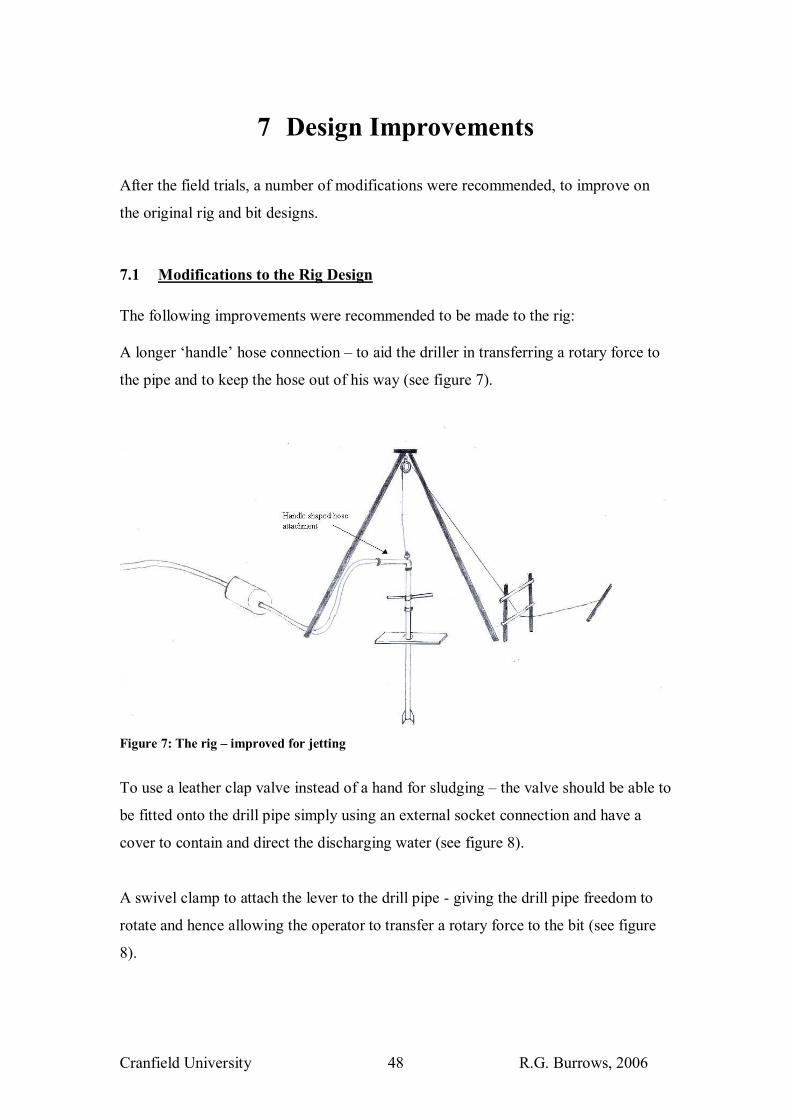
Cranfield University R.G. Burrows, 2006 48
7 Design Improvements After the field trials, a number of modifications were recommended, to improve on
the original rig and bit designs.
7.1 Modifications to the Rig Design The following improvements were recommended to be made to the rig: A longer �handle� hose connection � to aid the driller in transferring a rotary force to
the pipe and to keep the hose out of his way (see figure 7).
Figure 7: The rig � improved for jetting
To use a leather clap valve instead of a hand for sludging � the valve should be able to
be fitted onto the drill pipe simply using an external socket connection and have a
cover to contain and direct the discharging water (see figure 8).
A swivel clamp to attach the lever to the drill pipe - giving the drill pipe freedom to
rotate and hence allowing the operator to transfer a rotary force to the bit (see figure
8).
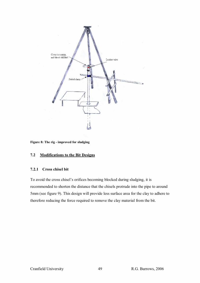
Cranfield University R.G. Burrows, 2006 49
Figure 8: The rig - improved for sludging
7.2 Modifications to the Bit Designs
7.2.1 Cross chisel bit To avoid the cross chisel�s orifices becoming blocked during sludging, it is
recommended to shorten the distance that the chisels protrude into the pipe to around
5mm (see figure 9). This design will provide less surface area for the clay to adhere to
therefore reducing the force required to remove the clay material from the bit.
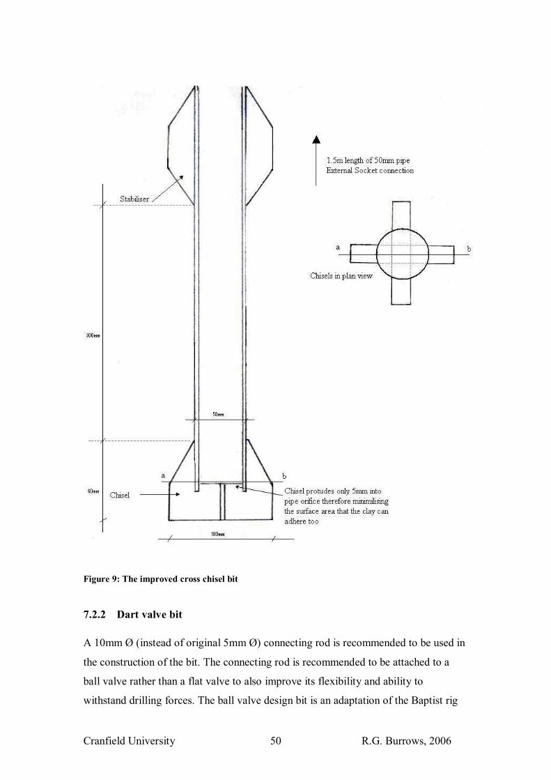
Cranfield University R.G. Burrows, 2006 50
Figure 9: The improved cross chisel bit
7.2.2 Dart valve bit A 10mm Ø (instead of original 5mm Ø) connecting rod is recommended to be used in
the construction of the bit. The connecting rod is recommended to be attached to a
ball valve rather than a flat valve to also improve its flexibility and ability to
withstand drilling forces. The ball valve design bit is an adaptation of the Baptist rig
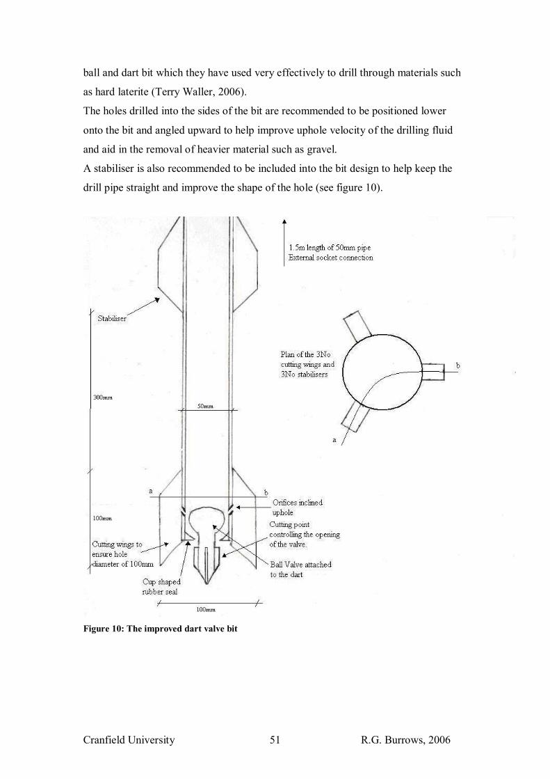
Cranfield University R.G. Burrows, 2006 51
ball and dart bit which they have used very effectively to drill through materials such
as hard laterite (Terry Waller, 2006).
The holes drilled into the sides of the bit are recommended to be positioned lower
onto the bit and angled upward to help improve uphole velocity of the drilling fluid
and aid in the removal of heavier material such as gravel.
A stabiliser is also recommended to be included into the bit design to help keep the
drill pipe straight and improve the shape of the hole (see figure 10).
Figure 10: The improved dart valve bit
Cranfield University R.G. Burrows, 2006 52
8 Discussion & Conclusions
The design drill kit formulated in this report does not attempt to �reinvent the wheel�;
all its component parts comprise basic technology currently being used by different
types of drill rigs. The design drill kit is intended more as a �swiss army knife�, a
useful tool for entrepreneurs and businesses in the developing world to adopt and take
forward.
Not enough field tests were carried out to assess with confidence whether the rig
design is flexible and adaptable enough to transfer successfully to an environment
such as Sub-Saharan Africa. Inadequate time and resources (specifically man power,
3-5 people are required to operate the rig) led to the following gaps in the field
testing:
• The rig was not tried in consolidated sediments, gravels, tropical residual soils
or hard rock.
• Some parts of the design, such as the rock hammer bit, were not investigated
• The rig was not tried to greater depths than 6.5m
• No wells were created and then tested to assess water quality/quantity
Encouraging case studies however illustrate that there is no reason why this rig could
not be successful. Similar technologies such as the Baptist drill rig and the EMAS rig
have successfully installed over 2000 and 10,000 wells respectively around the globe.
The tests that were carried out provided some very positive results. The test rig
worked very effectively as a drilling tool and proved that hand operated drilling is not
just feasible, but effective in drilling boreholes of diameters up to 120mm in clay and
sand.
During the testing, in four out of the six boreholes drilled, damage or loss was
sustained to part of the drill kit, specifically the bit. This highlights the importance of
parts being able to be made and repaired locally from locally available material.

Cranfield University R.G. Burrows, 2006 53
Jetting demonstrated to be the most effective hand operated drilling technique, jetting
through soils with clay contents of over 50% when combining rotary and percussive
forces to the bit. This came as a surprise after having read negative reports in the
literature on jetting performances in clay. However the combination of jetting, shock
and shear forces appears to work well in the soil at Silsoe, twice as effectively as
sludging and when compared with conventional forms of drilling it was found to hold
its own against the PatDrill 202 rotary rig and vastly outperform the Dando cable
percussion rig.
It is tempting to attribute part of this good performance to the bit designs, however not
enough data was collected to substantiate this, so one can only postulate that the bit
designs did successfully improve jetting performance.
In hindsight some of the controversy concerned with jetting could have stemmed from
comparing the rapidity of jetting in sand with jetting in clay. Metianu (1982) stated
that jetting speed can be as high as 1m/minute in coarse sand or as low as
0.1m/minute in heavy consolidated clay (borehole diameter not given)(from Marumo,
1987). 0.1m/minute is equivalent to 6m/hour, still a fast drilling rate and identical to
the results achieved by the cross chisel bit when jetting.
Although sludging and augering did not perform as well as jetting in the soils of
Cranfield University, Silsoe, there is no reason why they may not excel in other
materials. It would be very interesting to compare all the different techniques in a
number of different soil profiles to gain more of an insight into which technique
works better in which conditions. This type of research could lead to the creation of a
drill chart displaying the most effective means of drilling through various soils types.
A guidance book is considered an essential tool to be used alongside this drill kit.
Included in the book could be information such as the drill chart, health & safety
information, information on how to log a borehole and perhaps most importantly
guidance on how to develop the well and to install the filter and permanent casing
properly. This will enhance water quality and quantity and help ensure the well
installed will bring satisfaction to the consumer and improve its sustainability.

Cranfield University R.G. Burrows, 2006 54
One of the main lessons that came out of the fieldwork is that there is nothing that
will improve drilling speeds better than experience. It is only with experience that a
driller will be able to understand the rigs capabilities and be able to make
modifications to the design to facilitate its performance.
Setting up a hand operated drillers forum on the website may be a good way to
capture some of this knowledge and transfer it to new crews and drilling business
ventures.
The results have proved that in suitable circumstances, where the water table is
shallow (<35m) and where ground conditions are favourable, hand operated drilling is
a simple, low cost solution to access ground water resources.
The low costs associated with hand drilled wells potentially could be afforded by
farmers and village consortiums and a market could be created if the benefits of
having access to clean water can be seen to outweigh the cost.
This knowledge now needs to be transferred to the private sector of Sub-Saharan
Africa and other less developed regions around the globe.
Cranfield University R.G. Burrows, 2006 55
9 General Recommendations To test the different drilling techniques out in a number of different soil/rock types to discern which technique work best in which lithology. To create a hand book to accompany the rig design containing information such as best practices, health & safety, advice on drilling techniques, advice on how to log a borehole, advice on how to develop and install a well to ensure its sustainability and quality of service. To promote the rig design to the private sector market in Sub Saharan Africa in a region where there is a demand for clean water sources. To set up a hand operated drill rig internet forum to discuss issues concerned with hand operated drilling and exchanging ideas on how to improve techniques and performance.
Cranfield University R.G. Burrows, 2006 56
10 References Alito, G. (August, 2006) Drilling Cost in Africa, unpublished MSc Thesis, Cranfield University Andrews, J. (April, 1996) Water for the forgotten people � Botswana�s revolutionary well-jetting technology, Waterlines, volume 14 No.4 Ball, P. (May, 2006) spoken conversation, Director of PatDrill Bell, H. (1984) Design and development of a low cost jetting technique for shallow borehole construction, unpublished MSc Thesis, Cranfield University Cansdale, R. (2006) Bushproof/Canzee pumps www.bushproof.com/index.php?id=73 (Accessed 18/08/2006) Carter, R.C. (May, 2005) Human-powered drilling technologies: an overview of human-powered drilling technologies for shallow small diameter well construction, for domestic and agricultural water supply, First Edition http://www.rwsn.ch/documentation/skatdocumentation.2005-11-15.5533687184/file (accessed 15/07/06) Carter, R.C. (2001) Private Sector Participation in Low Cost Water Well Drilling. DFID Infrastructure and Urban Development Division KAR PROJECT R7126 Final Report. http://www.silsoe.cranfield.ac.uk/iwe/projects/lcdrilling/ (accessed 02/08/06) Clark, L. (1988) Field Guide to Water Wells and Boreholes, Open University Press Danert, K. (2003) Technology Transfer for development: Insights from the introduction of low cost water well drilling technology to Uganda, PHD Thesis, Cranfield University at Silsoe, Institute of Water and Environment - �16 principles on technology development and transfer� chapter 5 Danert, K. (April 2006) A Brief History of Hand Drilled Wells in Niger, RWSN Denyer, A. (1996) Low cost drilling for farmer managed garden irrigation with particular reference to Sub-Saharan Africa, unpublished MSc Thesis, Cranfield University
DFID (2006) Keeping our promises: A second update on DFID�s work in water and sanitation since the Water Action Plan, http://www.dfid.gov.uk/pubs/default.asp (accessed 07/07/06)
DiGiano, F.A. Andreottola, G. Adham, S. Buckley, C. Cornel, P. Daigger, G.T. Fane, A.G. Galil, N. Jacangelo, J. Pollice, A. Rittmann, B.E. Rozzi, A. Stephenson, T. Ujang, Z. (June 2004) Safe Water for Everyone: membrane bioreactor technology, Science in Africa
Cranfield University R.G. Burrows, 2006 57
http://www.scienceinafrica.co.za/2004/june/membrane.htm (accessed 05/07/06) Driscoll, F.G. (1986) Groundwater and Wells (second edition) Johnson Screens, Minnesota
Elson, B. Shaw, R. (1995) Simple Drilling methods, WEDC, Loughborough University http://www.lboro.ac.uk/well/resources/technical-briefs/43-simple-drilling-methods.pdf (accessed 12/06/06)
Elson, B. (1994) Affordable water supply and sanitation: low technology drilling, 20th WEDC Conference, Colombo, Sri Lanka http://www.lboro.ac.uk/wedc/papers/20/sessiong/elson.pdf (accessed 15/07/06) Emas home page (2006) http://www.emas-international.de/english/index_e.htm (Accessed 16/08/2006) Fookes, P.G. (1997) Tropical Residual Soils, Geological Society Engineering Group Working Party revised report, pub.Geological Society, London Garandeau, R. (August, 2006), spoken conversation, Cranfield University advisory board consultant for the Bill & Melinda Gates Foundation Haus, D.B. (January, 2005) Buddhistisches Haus / EMAS Drinking Water Development Project: Improvement of the drinking water supply through the training of well drillers and pump makers in Sri Lanka http://www.buddhistisches-haus.de/info/ReliefReport.pdf (accessed 15/07/06) Henson, G. (October, 2004) San Angelo church digs deep to help missionaries in Bolivia, The Baptist Standard http://www.baptiststandard.com/postnuke/index.php?module=htmlpages&func=display&pid=2381 (accessed 12/07/06)
Herwijnen, A.V. Roy, D (2002) Stone hammer � latest developments, Practica Foundation / ICCO CDHI http://www.practicafoundation.nl/library/stonehammer_recent.htm#top (accessed 08/08/2006) Jose, J. (19988) Studies and design improvements of low cost well jeting, unpublished MSc Thesis, Cranfield University Kavaruganda, J. M. (2005) Low Cost Drilling in Emergencies, unpublished MSc Thesis, Cranfield University Kenya Water for health organisation (2006) http://www.kwaho.org/t-drill.html (accessed 15/07/06)

Cranfield University R.G. Burrows, 2006 58
Knight, J. (1995) Low cost drilling methods: Improvements to sludging to penetrate hard layers, unpublished MSc Thesis, Cranfield University Lenton, R. Wright, A. (Feb, 2004) Interim Report of Task Force 7 on Water and Sanitation, Millennium Project, UN Development Group http://www.unmillenniumproject.org/documents/tf7interim.pdf (accessed 07/07/06) MacDonald, A.M. Davies, J. O�Dochartaigh, B.E. (2001) Simple methods for assessing groundwater resources in low permeability areas of Africa, BGS Commissioned Report CR/01/168N, DFID http://www-esd.worldbank.org/esd/ard/groundwater/pdfreports/Simple_%20methods_African_lowperm_areas_Pt1.pdf (accessed 14/08/2006)
Marumo, K. (1987) Low cost borehole drilling using water jetting techniques, unpublished MSc Thesis, Cranfield University Metianu, A. (1982) A simple method of jetting tubewells, waterlines, vol 1 no 1 pp 6-9 July 1982 � cited in Marumo, K. (1987) Low cost borehole drilling using water jetting techniques, unpublished MSc Thesis, Cranfield University Nichols, G. (1999) Sedimentology & Stratigraphy, Pub.Blackwell Science Ltd NWP (2006) Smart Water Solutions: Examples of innovative, low-cost technologies for wells, pumps, storage, irrigation and water treatment, third edition. http://practicafoundation.nl/smartwater/documents/NWPSWSV3ENGinternet040506.pdf (accessed 14/06/06) Osola, M.J. (1992) Low cost well drilling, unpublished MSc Thesis, Cranfield University Pirsa Minerals (July, 2006) Glossary of commonly cited regolith terms, department of primary industries and resources, Government of South Australia http://www.pir.sa.gov.au/pages/minerals/resources/regolith/glossary.htm:sectID=824&tempID=7 (Accessed 16/08/2006) Rogers, E.M. (2003) Diffusion of Innovations, fifth edition, Free Press Reade, 2006 READE Advanced Materials - Weight Per Cubic Foot And Specific Gravity http://www.reade.com/es/Reference-%10-Educational/Particle-Property-Briefings/Weight-Per-Cubic-Foot-And-Specific-Gravity.html (accessed 23rd July, 2006) UN Water (2006) Water a shared responsibility, The United Nations World water development report 2, UNESCO http://unesdoc.unesco.org/images/0014/001444/144409E.pdf (accessed 05/07/06)

Cranfield University R.G. Burrows, 2006 59
Van Herwijnen, A. Roy, D. (June 2002) Stonehammer � latest developments, Practica Foundation/ ICCO, CDHI. http://www.practicafoundation.nl/library/stonehammer_recent.htm#top (accessed 16/07/06) Waller, T. (August, 2006) Southland B.C. Community development missionary and project director for the NGO � Water for All: Agua para todos� Email: [email protected] Water for All : Agua para todos website (June 2006) http://www.geocities.com/h2oclubs/ (accessed 14/06/06) Wardle, C. (1999) Investigating into the effective use of a low cost water well drilling rig, unpublished MSc Thesis, Cranfield University World Bank (2006), Community Driven Development, http://web.worldbank.org/WBSITE/EXTERNAL/TOPICS/EXTSOCIALDEVELOPMENT/EXTCDD/0,,menuPK:430167~pagePK:149018~piPK:149093~theSitePK:430161,00.html (Accessed 12/08/2006)
World Health Organization (November 2004) Water, Sanitation and Hygiene Links to Health FACTS AND FIGURES � http://www.who.int/water_sanitation_health/factsfigures2005.pdf (accessed 09/07/06) Worth, M. (1998) A mechanism for percussion drilling of low cost water wells in developing countries, unpublished MSc Thesis, Cranfield University Wurzel, P. (2001) Drilling Boreholes for Handpumps, working papers on Water Supply and Environmental Sanitation, Volume 2, SKAT Zeug, H. (May, 2006) MSc Water Management, Community Water Supply drilling practical carried out on the 25th May 2006, Cranfield University
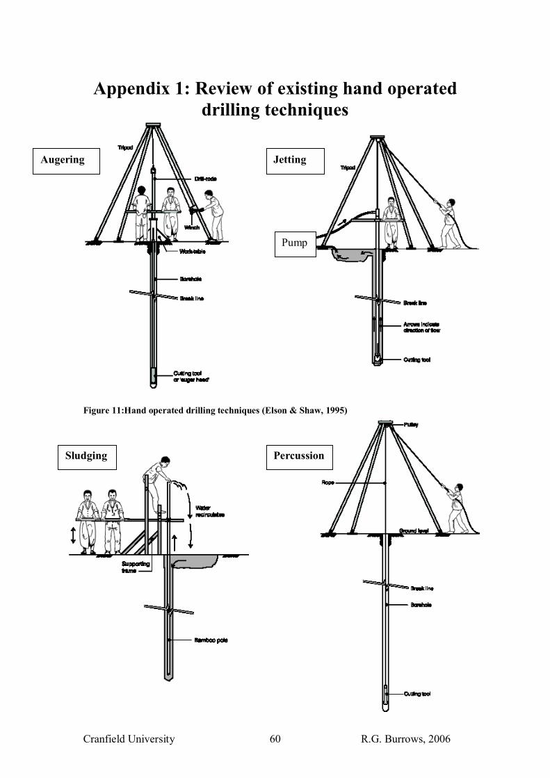
Cranfield University R.G. Burrows, 2006 60
Appendix 1: Review of existing hand operated drilling techniques
Figure 11:Hand operated drilling techniques (Elson & Shaw, 1995)
Pump
Augering
Sludging
Jetting
Percussion

Cranfield University R.G. Burrows, 2006 61
Adaptions of the Jetting Method
• Washbore temporary casing method: Temporary casing is inserted into the
hole as jetting takes place. Permanent casing is then fed through temporary
casing once hole is complete
• Bentonite Method: Hole is jetted with recycled drill mud.
• Self Jetting Well screen method, developed by Cansdale (1991). Reduces
hardware required to jet a well. A plastic ball valve at the base of the well
screen pipe allow water to jet out when installing well screen whilst a rubber
flap valve around the inner wall of the screen is held flat against it. When well
is developed with pump sucking water out of well the ball valve close sand
groundwater can flow in through the flap valve. (Denyer, 1996)
• Jetting with two pumps method. The final casing is jetted down
simultaneously with the jetting pipe.
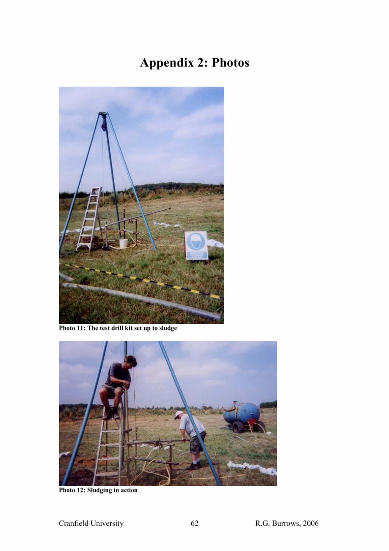
Cranfield University R.G. Burrows, 2006 62
Appendix 2: Photos
Photo 11: The test drill kit set up to sludge
Photo 12: Sludging in action
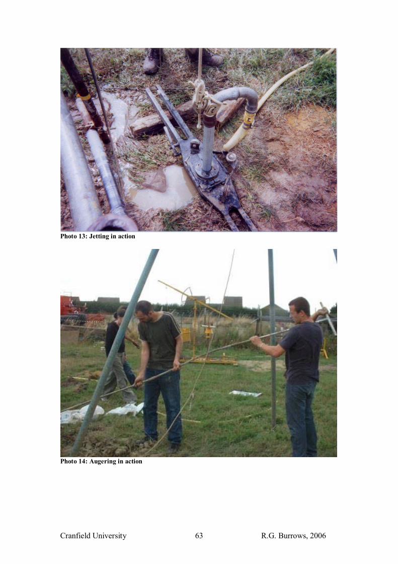
Cranfield University R.G. Burrows, 2006 63
Photo 13: Jetting in action
Photo 14: Augering in action

Cranfield University R.G. Burrows, 2006 64
Photo 15: The auger bits
Photo 16: The Oxfam auger kit
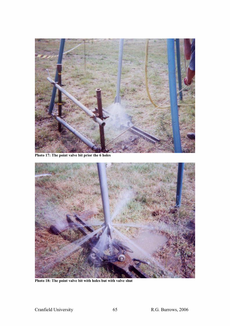
Cranfield University R.G. Burrows, 2006 65
Photo 17: The point valve bit prior the 6 holes
Photo 18: The point valve bit with holes but with valve shut

Cranfield University R.G. Burrows, 2006 66
Photo 19: The point valve bit � valve open
Photo 20: The point valve bit � post drilling
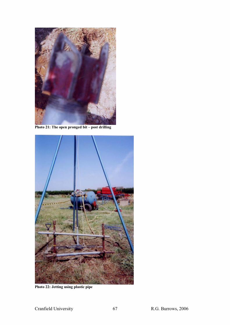
Cranfield University R.G. Burrows, 2006 67
Photo 21: The open pronged bit � post drilling
Photo 22: Jetting using plastic pipe
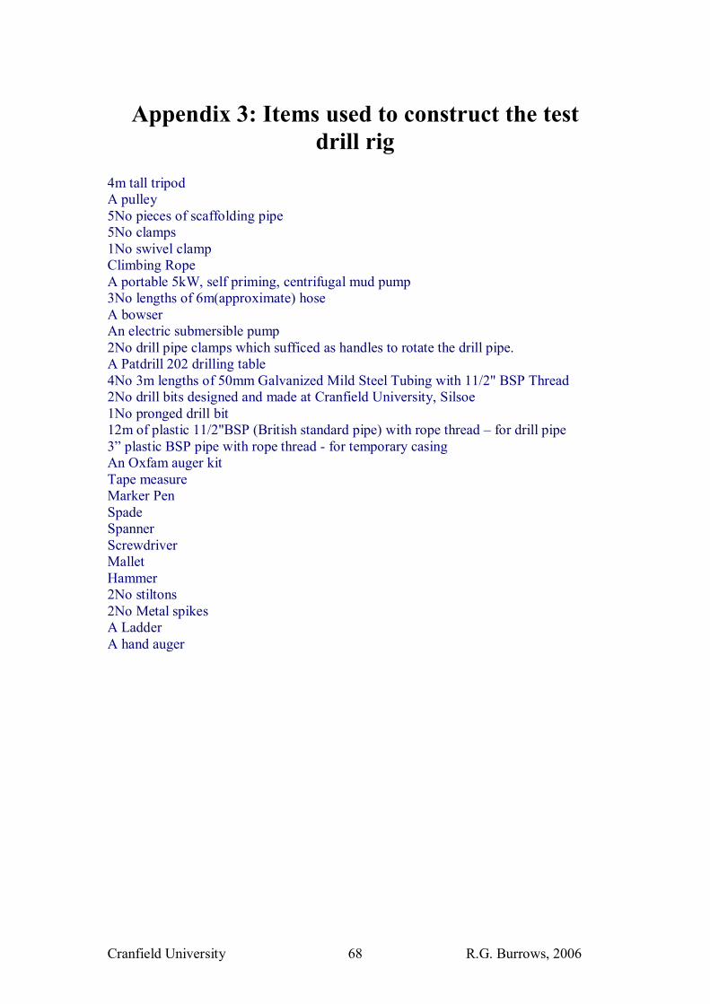
Cranfield University R.G. Burrows, 2006 68
Appendix 3: Items used to construct the test drill rig
4m tall tripod A pulley 5No pieces of scaffolding pipe 5No clamps 1No swivel clamp Climbing Rope A portable 5kW, self priming, centrifugal mud pump 3No lengths of 6m(approximate) hose A bowser An electric submersible pump 2No drill pipe clamps which sufficed as handles to rotate the drill pipe. A Patdrill 202 drilling table 4No 3m lengths of 50mm Galvanized Mild Steel Tubing with 11/2" BSP Thread 2No drill bits designed and made at Cranfield University, Silsoe 1No pronged drill bit 12m of plastic 11/2"BSP (British standard pipe) with rope thread � for drill pipe 3� plastic BSP pipe with rope thread - for temporary casing An Oxfam auger kit Tape measure Marker Pen Spade Spanner Screwdriver Mallet Hammer 2No stiltons 2No Metal spikes A Ladder A hand auger
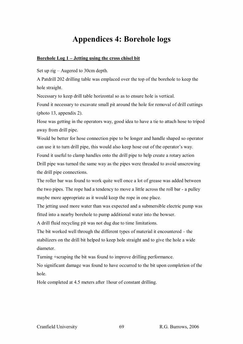
Cranfield University R.G. Burrows, 2006 69
Appendices 4: Borehole logs
Borehole Log 1 � Jetting using the cross chisel bit Set up rig � Augered to 30cm depth.
A Patdrill 202 drilling table was emplaced over the top of the borehole to keep the
hole straight.
Necessary to keep drill table horizontal so as to ensure hole is vertical.
Found it necessary to excavate small pit around the hole for removal of drill cuttings
(photo 13, appendix 2).
Hose was getting in the operators way, good idea to have a tie to attach hose to tripod
away from drill pipe.
Would be better for hose connection pipe to be longer and handle shaped so operator
can use it to turn drill pipe, this would also keep hose out of the operator�s way.
Found it useful to clamp handles onto the drill pipe to help create a rotary action
Drill pipe was turned the same way as the pipes were threaded to avoid unscrewing
the drill pipe connections.
The roller bar was found to work quite well once a lot of grease was added between
the two pipes. The rope had a tendency to move a little across the roll bar - a pulley
maybe more appropriate as it would keep the rope in one place.
The jetting used more water than was expected and a submersible electric pump was
fitted into a nearby borehole to pump additional water into the bowser.
A drill fluid recycling pit was not dug due to time limitations.
The bit worked well through the different types of material it encountered � the
stabilizers on the drill bit helped to keep hole straight and to give the hole a wide
diameter.
Turning +scraping the bit was found to improve drilling performance.
No significant damage was found to have occurred to the bit upon completion of the
hole.
Hole completed at 4.5 meters after 1hour of constant drilling.
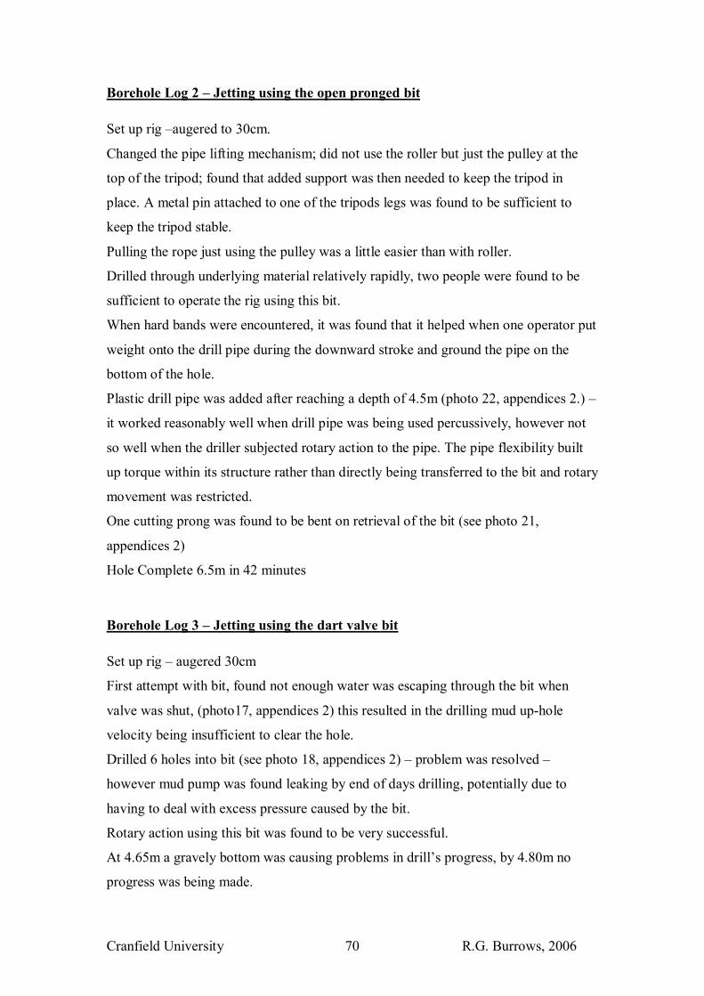
Cranfield University R.G. Burrows, 2006 70
Borehole Log 2 � Jetting using the open pronged bit Set up rig �augered to 30cm.
Changed the pipe lifting mechanism; did not use the roller but just the pulley at the
top of the tripod; found that added support was then needed to keep the tripod in
place. A metal pin attached to one of the tripods legs was found to be sufficient to
keep the tripod stable.
Pulling the rope just using the pulley was a little easier than with roller.
Drilled through underlying material relatively rapidly, two people were found to be
sufficient to operate the rig using this bit.
When hard bands were encountered, it was found that it helped when one operator put
weight onto the drill pipe during the downward stroke and ground the pipe on the
bottom of the hole.
Plastic drill pipe was added after reaching a depth of 4.5m (photo 22, appendices 2.) �
it worked reasonably well when drill pipe was being used percussively, however not
so well when the driller subjected rotary action to the pipe. The pipe flexibility built
up torque within its structure rather than directly being transferred to the bit and rotary
movement was restricted.
One cutting prong was found to be bent on retrieval of the bit (see photo 21,
appendices 2)
Hole Complete 6.5m in 42 minutes
Borehole Log 3 � Jetting using the dart valve bit Set up rig � augered 30cm
First attempt with bit, found not enough water was escaping through the bit when
valve was shut, (photo17, appendices 2) this resulted in the drilling mud up-hole
velocity being insufficient to clear the hole.
Drilled 6 holes into bit (see photo 18, appendices 2) � problem was resolved �
however mud pump was found leaking by end of days drilling, potentially due to
having to deal with excess pressure caused by the bit.
Rotary action using this bit was found to be very successful.
At 4.65m a gravely bottom was causing problems in drill�s progress, by 4.80m no
progress was being made.
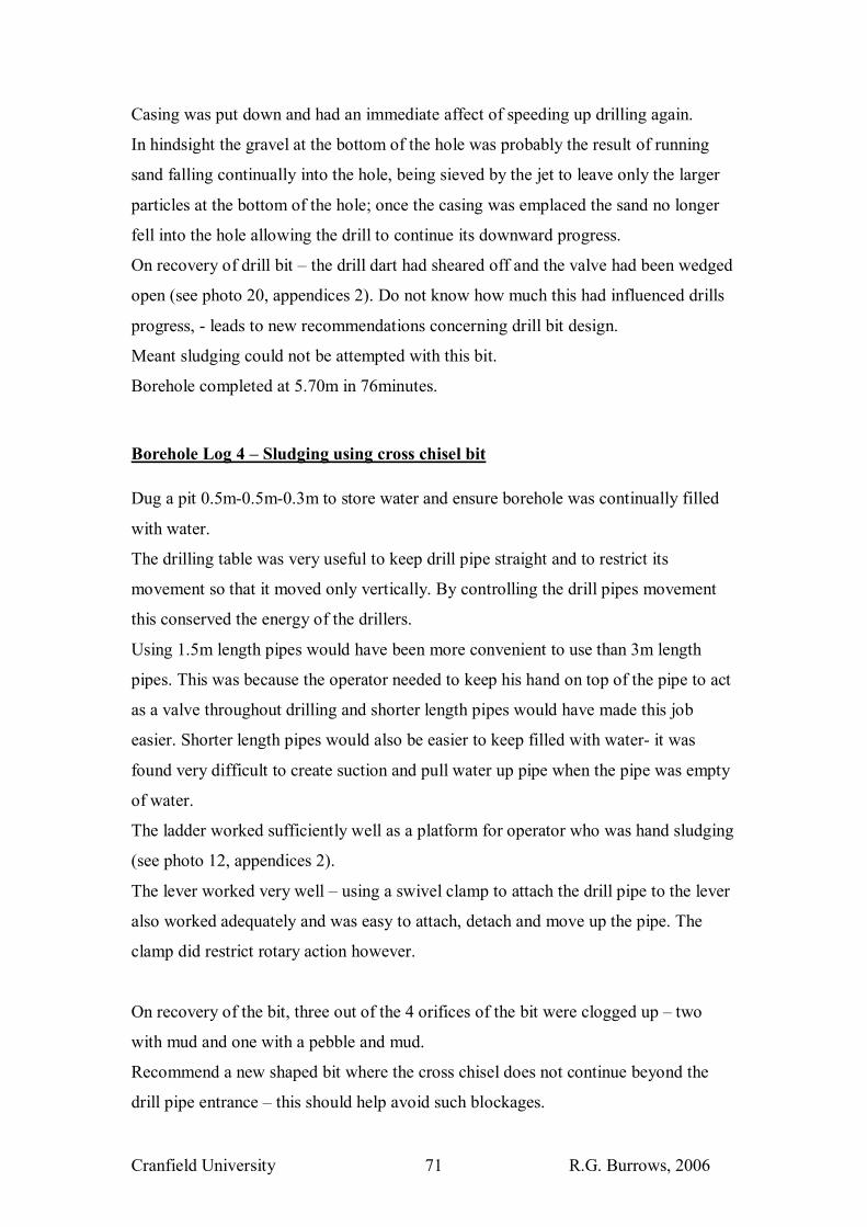
Cranfield University R.G. Burrows, 2006 71
Casing was put down and had an immediate affect of speeding up drilling again.
In hindsight the gravel at the bottom of the hole was probably the result of running
sand falling continually into the hole, being sieved by the jet to leave only the larger
particles at the bottom of the hole; once the casing was emplaced the sand no longer
fell into the hole allowing the drill to continue its downward progress.
On recovery of drill bit � the drill dart had sheared off and the valve had been wedged
open (see photo 20, appendices 2). Do not know how much this had influenced drills
progress, - leads to new recommendations concerning drill bit design.
Meant sludging could not be attempted with this bit.
Borehole completed at 5.70m in 76minutes.
Borehole Log 4 � Sludging using cross chisel bit Dug a pit 0.5m-0.5m-0.3m to store water and ensure borehole was continually filled
with water.
The drilling table was very useful to keep drill pipe straight and to restrict its
movement so that it moved only vertically. By controlling the drill pipes movement
this conserved the energy of the drillers.
Using 1.5m length pipes would have been more convenient to use than 3m length
pipes. This was because the operator needed to keep his hand on top of the pipe to act
as a valve throughout drilling and shorter length pipes would have made this job
easier. Shorter length pipes would also be easier to keep filled with water- it was
found very difficult to create suction and pull water up pipe when the pipe was empty
of water.
The ladder worked sufficiently well as a platform for operator who was hand sludging
(see photo 12, appendices 2).
The lever worked very well � using a swivel clamp to attach the drill pipe to the lever
also worked adequately and was easy to attach, detach and move up the pipe. The
clamp did restrict rotary action however.
On recovery of the bit, three out of the 4 orifices of the bit were clogged up � two
with mud and one with a pebble and mud.
Recommend a new shaped bit where the cross chisel does not continue beyond the
drill pipe entrance � this should help avoid such blockages.
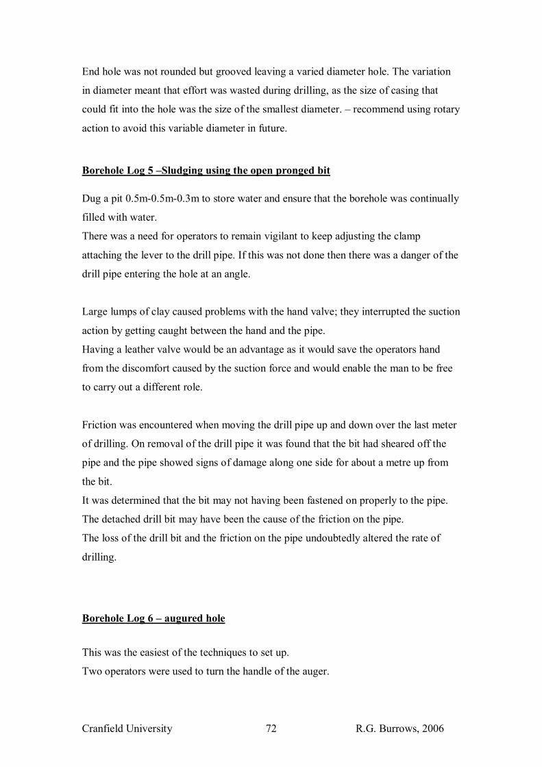
Cranfield University R.G. Burrows, 2006 72
End hole was not rounded but grooved leaving a varied diameter hole. The variation
in diameter meant that effort was wasted during drilling, as the size of casing that
could fit into the hole was the size of the smallest diameter. � recommend using rotary
action to avoid this variable diameter in future.
Borehole Log 5 �Sludging using the open pronged bit Dug a pit 0.5m-0.5m-0.3m to store water and ensure that the borehole was continually
filled with water.
There was a need for operators to remain vigilant to keep adjusting the clamp
attaching the lever to the drill pipe. If this was not done then there was a danger of the
drill pipe entering the hole at an angle.
Large lumps of clay caused problems with the hand valve; they interrupted the suction
action by getting caught between the hand and the pipe.
Having a leather valve would be an advantage as it would save the operators hand
from the discomfort caused by the suction force and would enable the man to be free
to carry out a different role.
Friction was encountered when moving the drill pipe up and down over the last meter
of drilling. On removal of the drill pipe it was found that the bit had sheared off the
pipe and the pipe showed signs of damage along one side for about a metre up from
the bit.
It was determined that the bit may not having been fastened on properly to the pipe.
The detached drill bit may have been the cause of the friction on the pipe.
The loss of the drill bit and the friction on the pipe undoubtedly altered the rate of
drilling.
Borehole Log 6 � augured hole
This was the easiest of the techniques to set up.
Two operators were used to turn the handle of the auger.

Cranfield University R.G. Burrows, 2006 73
The initial meter and a half was very easily drilled. Water was added to aid in the
drilling.
Found that the auger attaching rods were quite weak and 3 pipes were bent during the
drilling � the deeper the auger, the more easy the attaching rods could be deformed
(see photo 14, appendices 2).
It was difficult to remove the auger from the hole at times � The tripod was used to
assist and fell down because the pulling force was greater than the tripod�s stability.
To resolve this problem the rope was pulled down at a 50 degree angle from the
horizontal using the roller and the tripod was pegged down.
By turning the auger a little in the non digging direction before removing it helped
also in its retrieval.
On encountering a more sandy soil at 4.00m the bit was changed to the sand auger bit
� this worked effectively.
Diameter of hole was found to be 100mm
EOH � 4.15m deep dug in 62 minutes.
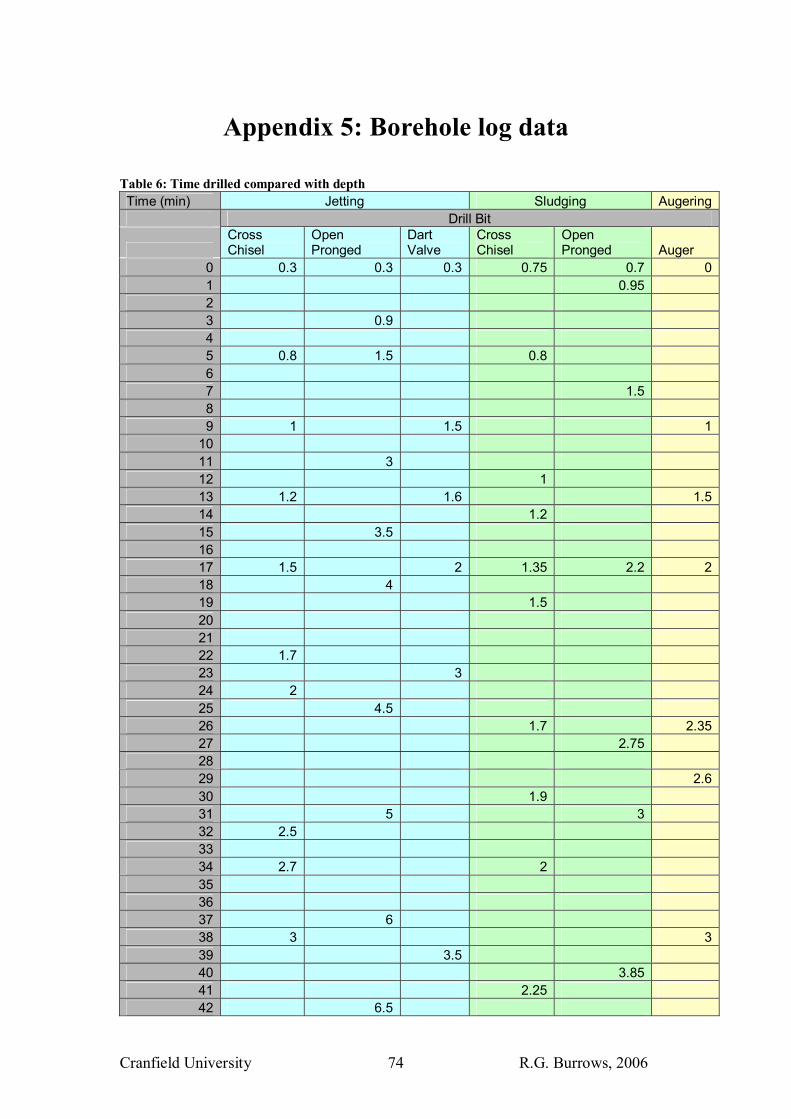
Cranfield University R.G. Burrows, 2006 74
Appendix 5: Borehole log data
Table 6: Time drilled compared with depth Time (min) Jetting Sludging Augering Drill Bit
Cross Chisel
Open Pronged
Dart Valve
Cross Chisel
Open Pronged Auger
0 0.3 0.3 0.3 0.75 0.7 01 0.95 2 3 0.9 4 5 0.8 1.5 0.8 6 7 1.5 8 9 1 1.5 1
10 11 3 12 1 13 1.2 1.6 1.514 1.2 15 3.5 16 17 1.5 2 1.35 2.2 218 4 19 1.5 20 21 22 1.7 23 3 24 2 25 4.5 26 1.7 2.3527 2.75 28 29 2.630 1.9 31 5 3 32 2.5 33 34 2.7 2 35 36 37 6 38 3 339 3.5 40 3.85 41 2.25 42 6.5

Cranfield University R.G. Burrows, 2006 75
43 3.5 44 45 4 2.5 46 4 3.1547 48 49 50 51 3.4552 4 53 4.5 2.7 4.5 54 55 4.15 56 57 58 4.3 4.0559 4.65 60 61 4.5 2.8 4.15
Hole Diameter 120mm 71mm 110mm 80mm 75mm 100mm
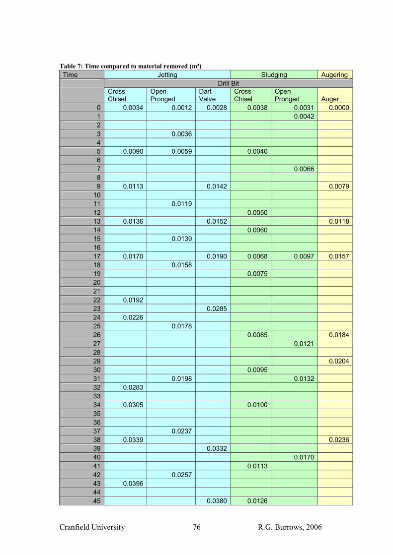
Cranfield University R.G. Burrows, 2006 76
Table 7: Time compared to material removed (m³) Time Jetting Sludging Augering Drill Bit
Cross Chisel
Open Pronged
Dart Valve
Cross Chisel
Open Pronged Auger
0 0.0034 0.0012 0.0028 0.0038 0.0031 0.00001 0.0042 2 3 0.0036 4 5 0.0090 0.0059 0.0040 6 7 0.0066 8 9 0.0113 0.0142 0.0079
10 11 0.0119 12 0.0050 13 0.0136 0.0152 0.011814 0.0060 15 0.0139 16 17 0.0170 0.0190 0.0068 0.0097 0.015718 0.0158 19 0.0075 20 21 22 0.0192 23 0.0285 24 0.0226 25 0.0178 26 0.0085 0.018427 0.0121 28 29 0.020430 0.0095 31 0.0198 0.0132 32 0.0283 33 34 0.0305 0.0100 35 36 37 0.0237 38 0.0339 0.023639 0.0332 40 0.0170 41 0.0113 42 0.0257 43 0.0396 44 45 0.0380 0.0126
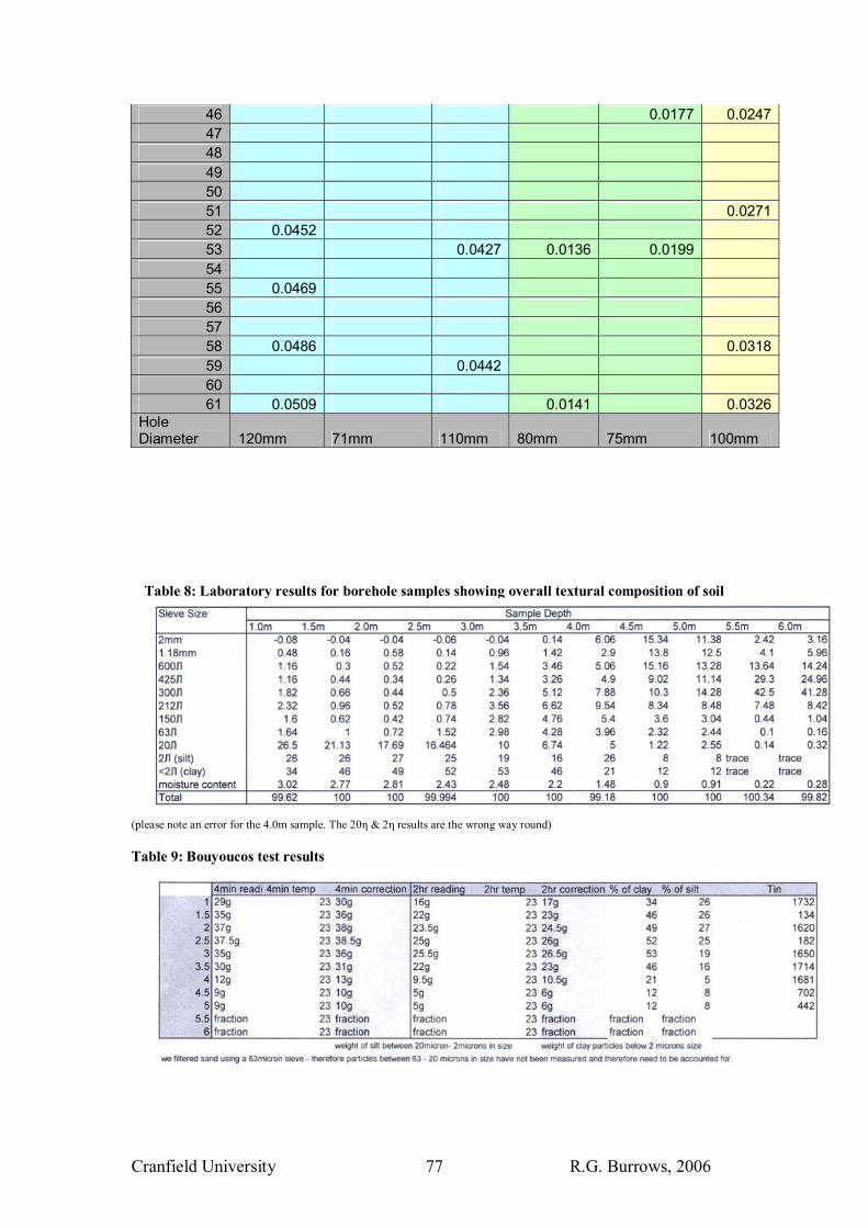
Cranfield University R.G. Burrows, 2006 77
46 0.0177 0.024747 48 49 50 51 0.027152 0.0452 53 0.0427 0.0136 0.0199 54 55 0.0469 56 57 58 0.0486 0.031859 0.0442 60 61 0.0509 0.0141 0.0326
Hole Diameter 120mm 71mm 110mm 80mm 75mm 100mm
Table 8: Laboratory results for borehole samples showing overall textural composition of soil
(please note an error for the 4.0m sample. The 20η & 2η results are the wrong way round) Table 9: Bouyoucos test results
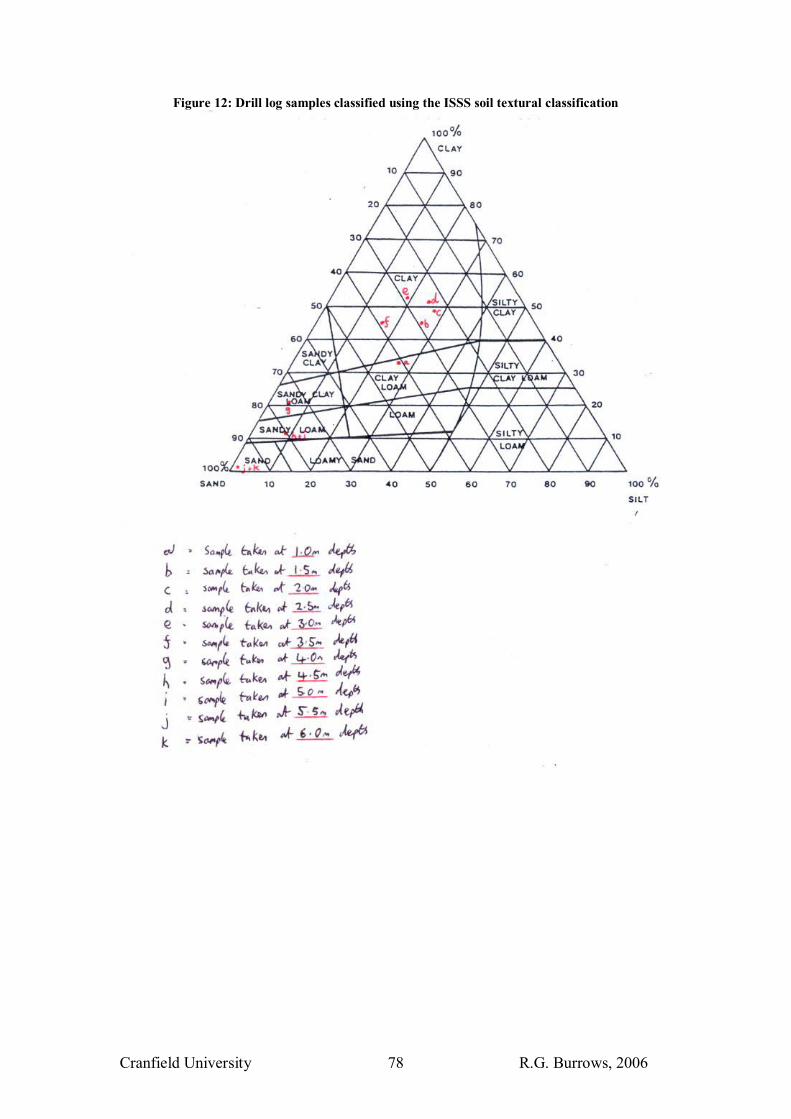
Cranfield University R.G. Burrows, 2006 78
Figure 12: Drill log samples classified using the ISSS soil textural classification

Cranfield University R.G. Burrows, 2006 79
Appendix 6: Drill Bit Designs
Design 1: Cross chisel bit
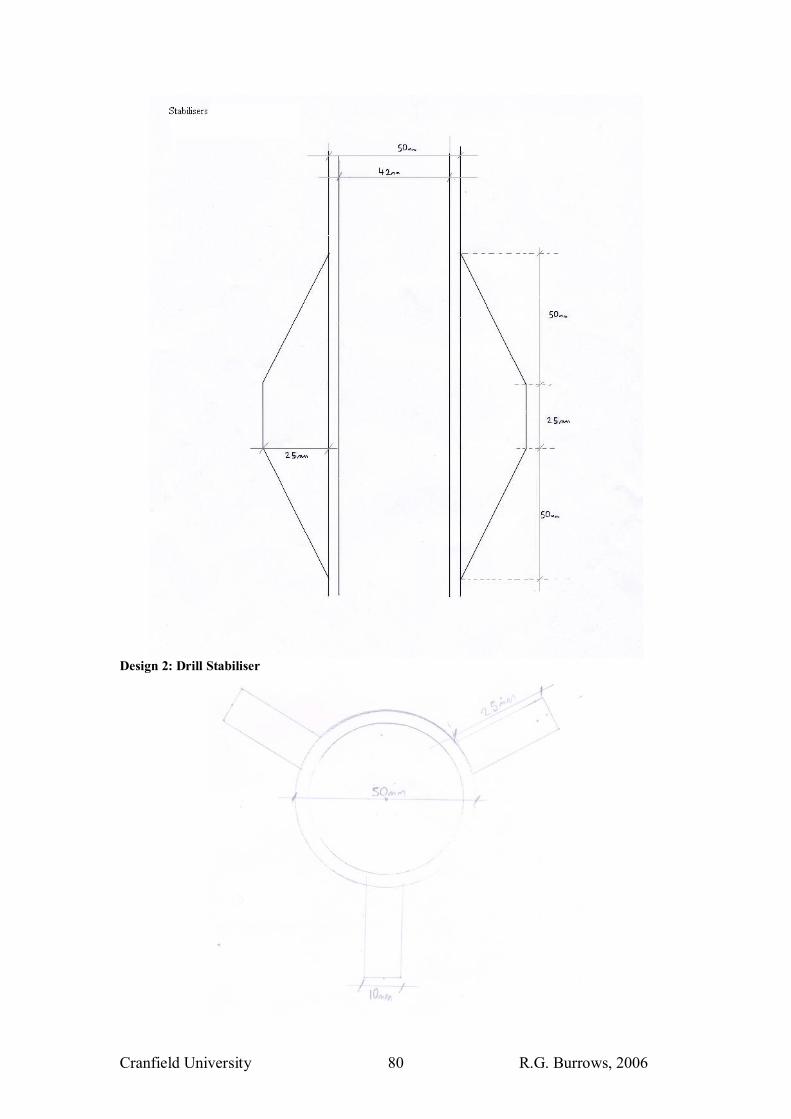
Cranfield University R.G. Burrows, 2006 80
Design 2: Drill Stabiliser
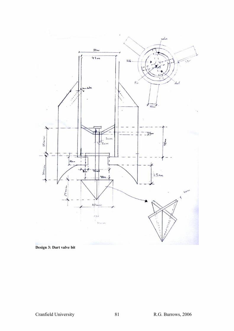
Cranfield University R.G. Burrows, 2006 81
Design 3: Dart valve bit
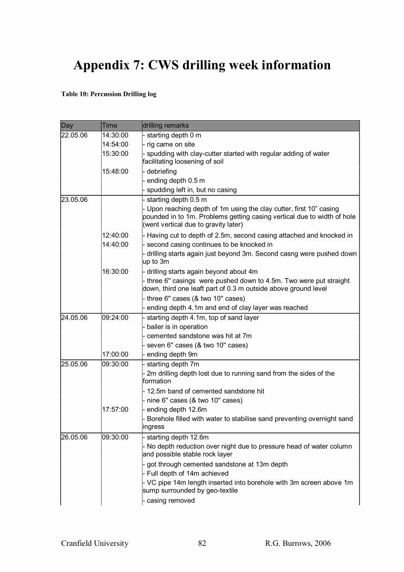
Cranfield University R.G. Burrows, 2006 82
Appendix 7: CWS drilling week information
Table 10: Percussion Drilling log Day Time drilling remarks 22.05.06 14:30:00 - starting depth 0 m 14:54:00 - rig came on site 15:30:00 - spudding with clay-cutter started with regular adding of water
facilitating loosening of soil 15:48:00 - debriefing - ending depth 0.5 m - spudding left in, but no casing 23.05.06 - starting depth 0.5 m - Upon reaching depth of 1m using the clay cutter, first 10� casing
pounded in to 1m. Problems getting casing vertical due to width of hole (went vertical due to gravity later)
12:40:00 - Having cut to depth of 2.5m, second casing attached and knocked in 14:40:00 - second casing continues to be knocked in - drilling starts again just beyond 3m. Second casng were pushed down
up to 3m 16:30:00 - drilling starts again beyond about 4m - three 6'' casings were pushed down to 4.5m. Two were put straight
down, third one leaft part of 0.3 m outside above ground level - three 6'' cases (& two 10'' cases) - ending depth 4.1m and end of clay layer was reached 24.05.06 09:24:00 - starting depth 4.1m, top of sand layer - bailer is in operation - cemented sandstone was hit at 7m - seven 6'' cases (& two 10'' cases) 17:00:00 - ending depth 9m 25.05.06 09:30:00 - starting depth 7m - 2m drilling depth lost due to running sand from the sides of the
formation - 12.5m band of cemented sandstone hit - nine 6'' cases (& two 10'' cases) 17:57:00 - ending depth 12.6m - Borehole filled with water to stabilise sand preventing overnight sand
ingress 26.05.06 09:30:00 - starting depth 12.6m - No depth reduction over night due to pressure head of water column
and possible stable rock layer - got through cemented sandstone at 13m depth - Full depth of 14m achieved - VC pipe 14m length inserted into borehole with 3m screen above 1m
sump surrounded by geo-textile - casing removed

Cranfield University R.G. Burrows, 2006 83
- Gravel pack poured in. Depth to gravel pack was expected/designed to be 10m. Measurement of actual depth to gravel pack was 7m. This inconsistency probably due to poor measurement of gravel poured in (using half bags left over from rotary hole) but more worryingly may be due to ingress of sand as casing removed
- 0-2.6m bentonite - 2.6-7m sand as stabiliser 16:15:00 - 7-14m gravel pack
Table 11: Rotary Mud Drilling Log Day time sample depth drilling remarks 22.05.2006 - suction pit size 0.8 x 0.8 x 0.6 m
(depth/length/width) - settling pit size 0.8 x 0.7 x 0.6 m 23.05.2006 09:30 - water viscosity measurement using marsh
funnel 27s/l 09:45 - drilling started 10:16 - first 1.5 m drilling pipe was added 10:23 - sample of cuttings taken 10:39 - drill pipes removed 10:56 - drilling stopped due to change in flow. Drill
head found to be blocked at 3m. Strainer blocked due to bad polymer mixing and grass
- drilling recommenced and water added to settling pit
11:02 - fourth length of drilling pipe added and cutting sample taken
11:07 - transition to sand at depth of 4.5m 11:15 - three quarts of polymer added 11:30 - cutting sample taken at depth of 5m 11:37 - water added to pit 11:46 - two quarts of polymer added - fifth length of drilling pipe added 11:57 - cutting sample taken at depth of 7.5m 12:03 - sixth length of drilling pipe added and
stone layer hit 12:11 - very hard cemented sandstone layer at an
approximate depth of 9m and water added to the pit
- drilling ceased at 9m 24.05.2006 09:30 - drilling depth at start 9m - between 10-11m cemented sand hit - reemer tool was installed to break through
sandstone layer - 12-13m again cemented sand layer was
hit
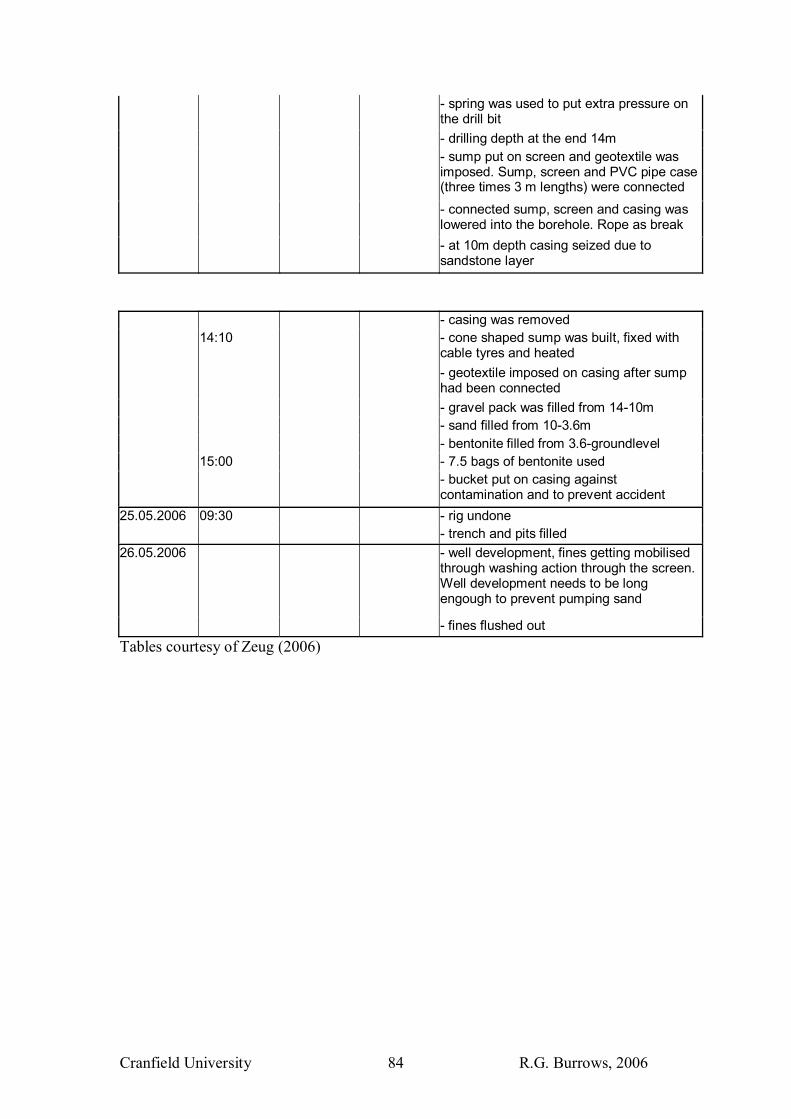
Cranfield University R.G. Burrows, 2006 84
- spring was used to put extra pressure on the drill bit
- drilling depth at the end 14m - sump put on screen and geotextile was
imposed. Sump, screen and PVC pipe case (three times 3 m lengths) were connected
- connected sump, screen and casing was lowered into the borehole. Rope as break
- at 10m depth casing seized due to sandstone layer
- casing was removed 14:10 - cone shaped sump was built, fixed with
cable tyres and heated - geotextile imposed on casing after sump
had been connected - gravel pack was filled from 14-10m - sand filled from 10-3.6m - bentonite filled from 3.6-groundlevel 15:00 - 7.5 bags of bentonite used - bucket put on casing against
contamination and to prevent accident 25.05.2006 09:30 - rig undone - trench and pits filled 26.05.2006 - well development, fines getting mobilised
through washing action through the screen. Well development needs to be long engough to prevent pumping sand
- fines flushed out Tables courtesy of Zeug (2006)