design of a high efficiency line start permanent magnet...
TRANSCRIPT

Design of a High Efficiency Line Start Permanent
Magnet Synchronous Motor
A report submitted to the School of Engineering and
Energy, Murdoch University in partial fulfilment of the
requirements for the degree of Bachelor of
Engineering
Andrew Fraser Student No: 30395635
2008

ii
ABSTRACT
Electric motor manufacturers are under increasing pressure through public demand to
produce more efficient machine designs. The growing cost of fossil fuels and an
increased awareness of the need to reduce greenhouse gas emissions have forced many
manufacturers to develop new and innovative motors which offer high reliability and
vastly greater operating efficiencies. This thesis investigates the design of a prototype
permanent magnet synchronous motor (PMSM) suitable for use in submersible
pumping applications. A PMSM offers excellent potential to increase motor efficiency
as, unlike conventional induction and synchronous motors, the rotor is (theoretically)
not subjected to any copper losses. The Infolytica Corporation’s “Magnet” finite
element analysis software was used to design, simulate and evaluate a line start six inch
PMSM and a six inch conventional induction motor. Prior to designing the new motors,
the software’s accuracy and suitability was assessed by simulating a pre-existing
induction motor. It was found that Magnet accurately modelled a real world motor with
only minor, quantifiable, errors. Most notably, the software’s lack of ability to fully
model three dimensional objects and account for machine iron and other stray losses led
to an almost constant overestimation of machine efficiency. A prototype six inch 1kW
standard induction motor and a 1kW PMSM were designed and simulated. Magnet
simulation results indicated that the PMSM was 14% more efficient than the induction
motor at full load and was capable of line starting from all initial rotor positions. Plans
for both motors were compiled and construction of both is expected to begin in the near
future. Physical testing of both machines and further development of the PMSM motor
for commercial applications is discussed.

iii
ACKNOWLEDGMENTS
Thank you to all the staff at Submersible Motor Engineering for giving me the
opportunity to carry out this research. In particular, I would like to thank Richard
Haffenden for his professional guidance and support throughout the internship period.
I would also like to acknowledge the support of the academic staff in the School of
Engineering at Murdoch University. Particular thanks go to Dr Greg Crebbin for acting
as my academic supervisor during the internship.
Finally, a special thank you goes to Sharon Ryder, Mika and Zed. Whilst this internship
was only six months, it is the culmination of four years study. Your continued support,
understanding and, in some cases, distractions throughout this time were greatly
appreciated.

iv
TABLE OF CONTENTS
ABSTRACT ..................................................................................................................... ii
ACKNOWLEDGMENTS .............................................................................................iii
LIST OF FIGURES ....................................................................................................... vi
LIST OF TABLES ........................................................................................................ vii
1 INTRODUCTION ................................................................................................... 8
1.1 Literature Review .............................................................................................. 9
1.1.1 Introduction to PMSM............................................................................... 10
1.1.2 PMSM Modelling ...................................................................................... 11
1.1.3 Position Sensoring and Control ................................................................ 13
1.1.4 Practical applications of PMSM Motors .................................................. 15
1.2 Outline of Present Work.................................................................................. 16
2 OVERVIEW OF SME AND SUBMERSIBLE MOTORS................................ 17
2.1 Company Overview ......................................................................................... 17
2.2 Introduction to Submersible Machines ........................................................... 17
2.3 Construction of Submersible Motors .............................................................. 20
3 SIMULATION WITH MAGNET ....................................................................... 23
3.1 Physical Motor ................................................................................................ 23
3.1.1 Motor Parameters ..................................................................................... 24
3.1.2 Physical Motor Testing ............................................................................. 25
3.2 Introduction to Magnet .................................................................................... 25
3.2.1 Modelling the Physical Motor ................................................................... 27
3.2.2 Simulation results ...................................................................................... 30
3.3 Discussion ....................................................................................................... 34
4 PMSM DESIGN .................................................................................................... 36
4.1 Design Parameters ........................................................................................... 36
4.1.1 Specified Motor Parameters ..................................................................... 36
4.1.2 Prototype Parameters ............................................................................... 37
4.2 Induction Motor Design .................................................................................. 37
4.2.1 Induction Motor Simulation ...................................................................... 39
4.2.2 Simulation Results ..................................................................................... 40
4.3 PMSM Design ................................................................................................. 41
4.3.1 Rotor Design ............................................................................................. 42

v
4.3.2 PMSM Simulation ..................................................................................... 46
4.3.3 Simulation Results ..................................................................................... 48
4.4 Discussion ....................................................................................................... 51
4.4.1 Six Inch Induction Motor .......................................................................... 52
4.4.2 Six Inch PMSM .......................................................................................... 53
5 CONCLUSION AND FUTURE WORK ............................................................ 56
5.1 Conclusion....................................................................................................... 56
5.2 Future Work .................................................................................................... 57
6 REFERENCES ...................................................................................................... 59
APPENDIX A- Attached Multimedia ......................................................................... 61
APPENDIX B- Test Motor ........................................................................................... 62
APPENDIX C- Calculations......................................................................................... 66
APPENDIX D- PMSM Design ..................................................................................... 68

vi
LIST OF FIGURES
Figure 1.1 Photovoltaic pump system (adapted from Henneberger, 1997) ...................... 8
Figure 1.2 PMSM drive system (adapted from Arroyo, 2006, pp. 13) ........................... 11
Figure 2.1 Typical submersible pump installation (SME, 2008) .................................... 18
Figure 2.2 Water filled submersible motor (SME, 2008) ............................................... 21
Figure 2.3 "Kingsbury" style thrust bearing (SME, 2008) .............................................. 22
Figure 3.1 10" Three-phase submersible motor (SME, 2008) ....................................... 23
Figure 3.2 Stator and rotor laminations........................................................................... 28
Figure 3.3 Completed 10” three-phase submersible motor model with components ..... 29
Figure 3.4 Simulated versus actual results of load placed on a 10” submersible motor . 31
Figure 3.5 Simulation of 10” three-phase submersible motor at steady state ................. 32
Figure 3.6 Four pole induction motor rotor .................................................................... 33
Figure 4.1 Completed induction motor model ................................................................ 40
Figure 4.2 Start-up characteristics of induction motor.................................................... 40
Figure 4.3 Radially magnetised (A) and circumferentially magnetised rotor (B) .......... 43
Figure 4.4 PMSM rotor model dimensions tested .......................................................... 44
Figure 4.5 Final rotor design ........................................................................................... 45
Figure 4.6 Rotor spacer and complete rotor assembly .................................................... 46
Figure 4.7 Completed PMSM model .............................................................................. 47
Figure 4.8 PMSM rotor speed - best and worst case initial rotor position ..................... 48
Figure 4.9 PMSM rotor current - best and worst case initial rotor position ................... 48
Figure 4.10 PMSM versus induction motor under load .................................................. 49
Figure 4.11 Starting performance of PMSM with reduced supply voltage .................... 50
Figure 4.12 Starting performance of PMSM with increased starting inertia .................. 50
Figure 4.13 Speed characteristic of PMSM with no rotor bars ....................................... 51
Figure 4.14 Rotor position of PMSM with no rotor bars ................................................ 51

vii
LIST OF TABLES
Table 3.1 10" Three-phase submersible motor parameters ............................................. 24
Table 3.2 10” Three-phase submersible motor performance data .................................. 25
Table 3.3 Component materials of 10” three-phase submersible motor ......................... 28
Table 3.4 Winding data of 10” three-phase submersible motor...................................... 29
Table 3.5 Simulated versus actual results of load placed on a 10” submersible motor .. 31
Table 4.1 Design parameters of submersible motor........................................................ 36
Table 4.2 Prototype parameters of induction motor and PMSM .................................... 37
Table 4.3 Stator-rotor slot combinations (AC Motor Design, 1990, pg 45).................... 38
Table 4.4 Induction motor materials ............................................................................... 39
Table 4.5 Simulation results of induction motor ............................................................. 40
Table 4.6 PMSM materials ............................................................................................. 47
Table 4.7 PMSM versus induction motor under load ..................................................... 49

8
1 INTRODUCTION
Many remote areas of Australia have no direct access to a mains water supply like that
found in the more populated regions. Instead, “standalone” systems must be designed
and installed in order to provide this essential service to the residents living in these
areas. A standalone system can vary substantially in magnitude, ranging from a simple
windmill driving a pump to provide water for live stock up to large scale electrical bore-
pumps supplying water to entire remote communities and townships. Many of these
larger systems have traditionally been powered by standalone diesel generators.
A growing trend nowadays is to incorporate some form of renewable resource whenever
possible within a remote water pumping installation. The reasons for this are twofold;
firstly, the growing cost of fossil fuels and concern regarding gas emissions are making
it unviable to run diesel generators for extended periods and, secondly, the geographical
remoteness of these areas dictates that a system must be reliable and require minimal
operator maintenance. A correctly designed and installed renewable system will reduce
the amount of operator maintenance required as these systems will generally be self
operating.
Due to climatic conditions, most remote areas of Australia are highly suited for the use
of photovoltaic (PV) supplies, making them a natural choice for use in a remote water
pumping installation. Figure 1.1 illustrates the major components of a generalised
photovoltaic pumping system. An individual system can take many different forms and
is very much dependent on the environment it is to be installed in and the demand for
water. Many options are available in regards to the type and number of solar cells
required, including the option of supplementing the supply with a back-up generator, a
battery bank or another form of renewable electricity.
Figure 1.1 Photovoltaic pump system (adapted from Henneberger, 1997)
Maximising power efficiency is of great importance in these installations as this directly
reduces the initial outlay and ongoing running costs of the system over its lifetime. This

9
thesis reviews prior work and investigates a technique to minimise the power losses
within the three phase motor itself. The benefit of focusing on the motor is that it can
increase the efficiency of the overall system, regardless of the electricity supply used
(providing the supply is adequate).
The body of this thesis reviews a new style of high efficiency three phase motor suitable
for use with a photovoltaic supply. The motor was designed and simulated using the
software package “MagNet” released by the Infolytica Corporation. In order to confirm
the accuracy of MagNet and to become familiar with the software package, a number of
simulations were run on pre-existing three phase induction motor designs. The
simulated data was compared to that taken from the physical machines. Next, a 1kW
induction motor and a line start permanent magnet synchronous motor (PMSM) were
designed and simulated. Direct comparison of the efficiency of the two motor designs
was made using simulations carried out in Magnet. Future development and testing
required to produce an efficient, commercially viable motor for use in remote water
pumping systems is discussed.
1.1 Literature Review
According to the Standards for Energy Efficiency of Electric Motor systems (SEEEM,
2008), electric motors account for up to forty percent of the total world electricity
consumption. Further, the Australian Minimum Energy Performance Standards (MEPS,
2008) reports that around seventy percent of the electricity used in the industrial sector
in Australia is utilised via electric motor drives. Recent years have seen a dramatic
increase in research to improve motor efficiencies. The focus has been on techniques to
improve the efficiency of three phase induction motors (by far the most common motor
used in industry) and to develop new, more efficient, motor types such as the permanent
magnet synchronous motor (PMSM).
Three phase induction motors are commonly used in submersible motor applications.
These motors are relatively simple in construction and their operating characteristics are
well known. Fitzgerald, Kingsley and Umans (2003, pp. 678-679) described a range of
modifications to improve their efficiency. One means is to minimise the internal losses,
such as the stator winding I2R losses. This can be done by increasing the slot area so
that more copper can be used. The result is a larger cross-sectional area of windings

10
and a reduction in the stator resistance. Rotor copper losses in squirrel cage induction
motors can be reduced by modifying the shape and size of the rotor bars. Core losses
can be reduced by decreasing the magnetic flux density in the iron of the machine. This
can be done by increasing the volume or quality of iron used in the machine. Also, for a
given flux density, eddy current losses can be reduced by using thinner iron laminations.
A downside of these efficiency improvement techniques is that they cannot be easily
done without over-sizing the original motor. This results in a trade-off between cost
and efficiency. Motors of more efficient design generally require more material and are
therefore physically larger and more expensive than a less efficient design (Fitzgerald,
Kingsley and Umans, 2003, pp. 678-679).
1.1.1 Introduction to PMSM
Resizing the motor is not a viable option when looking at improving the efficiency of a
submersible motor coupled to a pump. The outer diameter of these motors is dictated
by the inner diameter of the bore hole in which it is to be installed. Therefore, a
different motor must be sourced that achieves higher power efficiencies without overly
increasing physical size. One such example is the PMSM which contains permanent
magnets embedded in the rotor. These polyphase synchronous motors are similar to
traditional synchronous machines with the exception that the field windings are replaced
by permanent magnets. Although PMSM designs have been discussed in research
literature over the past twenty to thirty years, they have only recently gained popularity
in industry. This is due to increased interest in reducing greenhouse gas emissions and
to the greater availability and cost effectiveness of the rare earth materials used to
manufacture the permanent magnets.
The most basic construction of a PMSM consists of a polyphase wound stator (which, in
some cases, may be identical to an induction motor stator) with a rotor consisting of
permanent magnets within a laminated iron core mounted on a shaft. The magnets may
be physically mounted on the circumference of the rotor (known as the surface mounted
PMSM) or embedded within the rotor laminations (known as the interior PMSM). The
surface mounted PMSM is generally easier to construct as the magnets are simply glued
to the rotor’s exterior. A downside of this design is that they are only suited for slower
speed applications due to the risk of the magnets detaching from the rotor at higher
11
speeds. The interior PMSM is a more complex design, however the physical nature of
the rotor provides protection to the magnets at higher operating speeds.
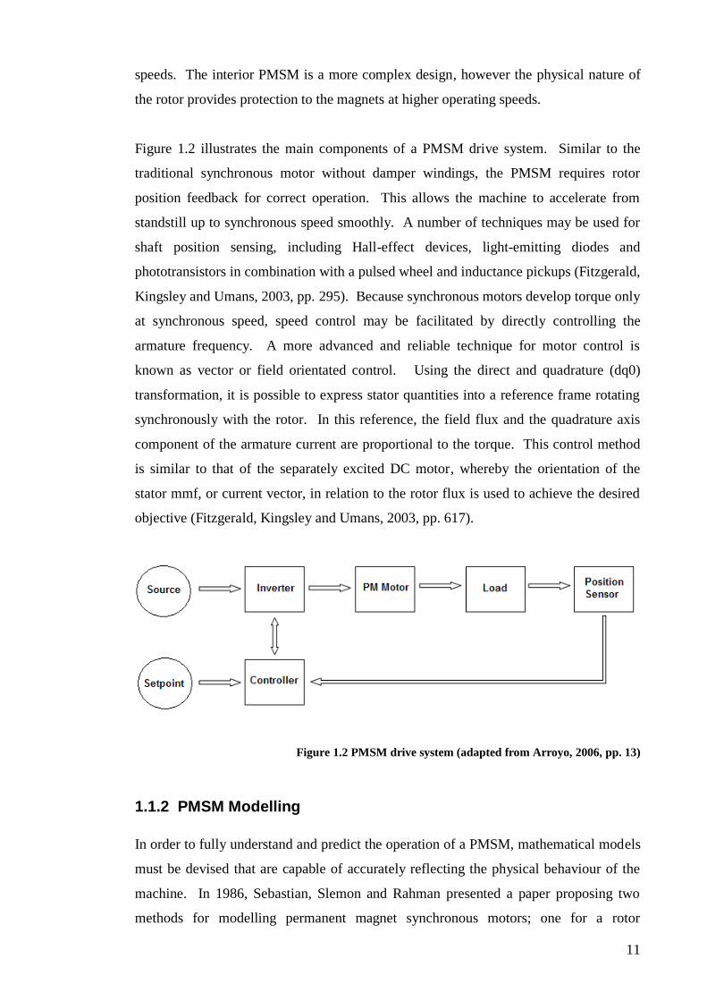
Figure 1.2 illustrates the main components of a PMSM drive system. Similar to the
traditional synchronous motor without damper windings, the PMSM requires rotor
position feedback for correct operation. This allows the machine to accelerate from
standstill up to synchronous speed smoothly. A number of techniques may be used for
shaft position sensing, including Hall-effect devices, light-emitting diodes and
phototransistors in combination with a pulsed wheel and inductance pickups (Fitzgerald,
Kingsley and Umans, 2003, pp. 295). Because synchronous motors develop torque only
at synchronous speed, speed control may be facilitated by directly controlling the
armature frequency. A more advanced and reliable technique for motor control is
known as vector or field orientated control. Using the direct and quadrature (dq0)
transformation, it is possible to express stator quantities into a reference frame rotating
synchronously with the rotor. In this reference, the field flux and the quadrature axis
component of the armature current are proportional to the torque. This control method
is similar to that of the separately excited DC motor, whereby the orientation of the
stator mmf, or current vector, in relation to the rotor flux is used to achieve the desired
objective (Fitzgerald, Kingsley and Umans, 2003, pp. 617).
Figure 1.2 PMSM drive system (adapted from Arroyo, 2006, pp. 13)
1.1.2 PMSM Modelling
In order to fully understand and predict the operation of a PMSM, mathematical models
must be devised that are capable of accurately reflecting the physical behaviour of the
machine. In 1986, Sebastian, Slemon and Rahman presented a paper proposing two
methods for modelling permanent magnet synchronous motors; one for a rotor

12
construction with protruding magnets and another for embedded magnet rotors. Models
were represented in direct axis and quadrature axis (dq0) variables. Physical tests were
conducted and the results were compared to those obtained analytically. It was
concluded that the models constructed were sufficient for use in prediction purposes.
This theoretical modelling of the PMSM was further defined by Pillay and Krishnan
(1988) in a discussion paper regarding classification of permanent motor drives. The
authors proposed two categories, namely permanent magnet synchronous motors
(PMSM) and brushless direct current motors (BDCM). It was stated that “the PMSM
has a sinusoidal back emf and requires sinusoidal stator currents to produce constant
torque while the BDCM has a trapezoidal back emf and requires rectangular stator
currents to produce constant torque” (Pillay and Krishnan, 1988). The PMSM modelled
was very similar to a wound rotor synchronous motor without damper windings (for self
starting). Equations were derived in the rotor reference frame and equivalent PMSM
electric circuits were described. The research indicated that the PMSM model could be
derived from the direct- and quadrature-axis (dq0) models of synchronous machines
with the equations for the damper windings and field current dynamics removed.
Dehkordi, Gole and Maguire (2005) presented the implementation of a model for a
permanent magnet synchronous motor on a real time digital simulator. Two modelling
approaches were adopted; firstly, the traditional dq0 model and secondly, the embedded
phase domain model. The latter seeks to model the machine as a set of time varying
mutual inductances. Real Time Digital Simulators (RTDS) were used to implement and
test both models. “The real time digital simulator is a combination of specialized
computer hardware and software designed specifically for the solution of power system
electromagnetically [sic] transients in real-time,” (Dehkordi, Gole and Maguuire, 2005).
The two models were simulated and the results compared in both transient and steady
state situations. It was found that the results of each model were identical, however the
embedded phase domain model proved to be more stable when simulated with larger
time step intervals. The findings of this report confirm the validity of the dq0 and phase
domain models, concluding that both models are sufficiently accurate in modelling a
permanent magnet synchronous motor drive.
The modelling techniques presented thus far have been analytical and can generally be
solved in seconds using a software program such as Matlab (Libert, Soulard, Engstrom,

13
2002). The benefit of these techniques is that parameters of a model can be calculated
quickly and with minimal computational time. A far more accurate and precise model
for electric motor designs can be constructed using a method known as the time
stepping finite element method (FEM). The FEM describes the electromagnetic fields
of machines by finite element equations that may be coupled to external mechanical and
circuit equations to produce an accurate simulation of the overall system (Ho and Fu,
1997). In the finite element method of analysis, a geometric model of the machine is
divided into a mesh of elements, each containing a field represented by a polynomial
with unknown coefficients. The finite element analysis is the solution of the set of
equations for the unknown coefficients (Infolytica, 2007). The FEM is gaining in
popularity as computers increase in power and software techniques are implemented
that reduce the computational time required to find a solution (Ho and Fu, 1997). One
such software package is Magnet, produced by the Infolytica Corporation, which has
been used extensively in this thesis.
1.1.3 Position Sensoring and Control
As described earlier and shown in Figure 1.2, a PMSM requires sophisticated control
techniques with rotor position feedback. Whilst it would be feasible to incorporate a
variable frequency drive to control a submersible motor, prior practical experience at
SME has shown that rotary position encoders installed in submersible motors are
unreliable (Haffenden, 2008). In 1991, Wu and Slemon proposed the use of a sensor-
less control for a PMSM. The authors described a control method for a permanent
magnet motor drive with sinusoidal phase current supply using stator voltage and
current signals. The voltage and current signals were used to calculate a flux linkage
position signal through which the phase angle of the stator current could be controlled
to maintain near unity power factor over a wide range of torque and speed. As the drive
had a low frequency limit of approximately 1 Hz, an open loop starting program was
used to accelerate the motor up to the low limit frequency from standstill. Tests
performed using a 5kW 1800rpm permanent magnet motor with surface mounted
magnets indicated that the design was suitable for sensor-less speed control. However,
further examination of the literature regarding sensor-less control of the PMSM
revealed that the technology is still very much in its infancy. Many research papers
have been released on the subject but, to date, no reliable practical example has been
constructed.
14
The positioning and feedback control requirements discussed above can be avoided with
the use of a line-start line-run PMSM (LS-PMSM). As the name implies, these
machines are capable of line starting and running directly from a mains supply. These
motors work on a similar principle to a traditional synchronous motor, having damper,
or amortisseur, windings fitted to the rotor (usually in the form of a squirrel cage).
During start-up, the damper windings in the rotor allow the machine to accelerate from
standstill to near synchronous speed (similar to an induction motor). Once the machine
nears synchronous speed, the rotor locks into synchronism with the rotating emf within
the stator, and the machine operates as a synchronous motor. Theoretically, when
operating at synchronous speed there is no field, or rotor, current present in the motor
(unlike traditional induction motors), therefore, the rotor is not subject to any copper
losses. This property makes the PMSM significantly more efficient than a comparably
sized induction motor.
In 1984, Miller presented a study describing the starting process of line-start permanent
magnet AC motors. It was stated that “the line start PM motor is a very high efficiency
synchronous motor designed to operate at a fixed voltage and frequency from the same
power supply as induction motors” (Miller, 1984, pp.1822). The excitation is provided
through two means, namely by the line current and by permanent magnets mounted on
the rotor. A squirrel cage type rotor allows the motor to accelerate from a standstill.
Synchronization resulting from the action of synchronizing torques is attributable partly
to the magnets and partly to the difference in reactance between the direct and
quadrature axis (reluctance torque) of the rotor. Presented in the paper were two
common rotor magnet mounting configurations for line start machines - the radial flux
orientation and the circumferential flux orientation. Particular emphasis was placed on
the analysis of factors that influenced the synchronizing capability of each design. It
was demonstrated that the magnet alignment torque contributed more to the
synchronizing capability of the machine than the reluctance torque, meaning the PM
motor provides better starting performance than a comparably sized reluctance motor.
One disadvantage investigated was that the magnets produced a braking torque at all
speeds which reduced the average asynchronous torque. This indicated that a poorly
designed PMSM could make synchronization more difficult and, in some cases,
impossible.

15
The above work was continued by Chaudhari, Pillai and Fernandes who, in 1998,
presented a paper introducing a new rotor geometry for a line start permanent magnet
motor. The new rotor design eliminated the drawbacks of the more conventionally used
rotor geometries (the radial flux geometry and the circumferential flux geometry) and
showed high potential for energy saving with no substantial increase in machine cost.
The rotor design was a hybrid type, consisting of elements of both the radial and
circumferential rotors, allowing for up to 25% higher air gap magnet flux density than
conventional designs. Finite element modelling techniques were used to ascertain the
effect of variation in magnet size, magnet material and angle of magnet inclination prior
to finalising the design. Whilst the new design was not physically tested, a nonlinear
model was developed which indicated that the proposed design would successfully line
start and display a high power factor and efficiency.
1.1.4 Practical applications of PMSM Motors
The previous studies were mainly based on theoretical experiments and prototype
motors. In 1997, Henneberger, Van Haute, Hameyer and Belmans published a project
focused on the design and implementation of a submersible permanent magnet motor
for use in a photovoltaic pump system. A 3.8kW permanent magnet motor was
developed by modifying a 3.2kW standard induction motor. New stator windings were
installed and a rotor containing permanent magnets and an asymmetrical rotor cage was
constructed. The rotor cage allowed the motor to operate in an “open loop” mode at
start-up and removed the requirement for a shaft sensor. A commercial solar inverter
was modified to include maximum power point tracking and specific protection
measures to ensure reliable operation under severe conditions. Testing revealed that the
2 pole pair permanent magnet motor was significantly more efficient than an equivalent
sized induction motor and operated at a steady state efficiency of 92.2% with a
mechanical power output of 3.48kW at 2200 rpm. The findings of this project imply
that the selection of a PMSM with line starting capabilities will be suitable for use in a
submersible motor powered by a photovoltaic system.
Similar research was conducted by Libert, Soulard and Engstrom who, in 2002,
presented their findings on the design of a 75kW 4-pole line start PMSM to be used in a
submersible pump. Different rotor geometries were tested and the performances of the
motors compared using finite element simulations to calculate the equivalent electrical
parameters. A design was found that gave satisfying results during the transient start up

16
period and was found to be more efficient than an equivalent induction motor when
running at a steady state.
The PMSM has also been found to be suitable for use in a range of other practical
applications. Ramsden et al, in 2002, released an article discussing high performance
electric machines suitable for use in renewable energy generation and high efficiency
drives. The paper listed several applications for the PMSM including submersible
pumps, electric car motor drives and high efficiency motors for household equipment.
Also discussed was the use of permanent magnet synchronous generators for use in
wind turbines and other forms of renewable electricity generation.
The above findings indicate that PMSMs will have an increasing role in both industrial
and domestic markets as public demand for more power efficient machines increases.
This thesis investigates the suitability of a circumferentially magnetised PMSM for use
as a 1kW submersible pump. It is hypothesised that the PMSM will have a significantly
higher efficiency than a similarly sized induction motor and that, with the incorporation
of damper windings in the rotor, no complex control and monitoring hardware will be
required to run the machine. At the same time, the suitability of finite element analysis
(through the use of Magnet) for the simulation of three phase submersible machines is
assessed.
1.2 Outline of Present Work
This thesis is divided into 5 parts. Chapter two introduces Submersible Motor
Engineering (SME) and discusses submersible motors in general. Chapter three
evaluates Magnet software by simulating a pre-existing SME submersible induction
motor. The data gathered from the simulation is compared to that taken from the
physical machine and conclusions are drawn as to the accuracy and applicability of the
simulation software. Chapter four discusses the design evolution of the PMSM.
Prototype induction and permanent magnet synchronous motors are designed and
simulated using Magnet. Comparisons are made between the simulated efficiency and
performance of the two machines. Chapter five presents general conclusions and
recommendations for future work.

17
2 OVERVIEW OF SME AND SUBMERSIBLE MOTORS
This chapter introduces Submersible Motor Engineering (SME) and provides a brief
overview of the company. Included is a description of the machines manufactured at
SME and a general introduction to submersible motors.
2.1 Company Overview
Submersible Motor Engineering (SME) design, manufacture and service submersible
electric motors that can be used in a variety of applications. SME is a 100% Australian
owned company based in Maddington, Western Australia, employing approximately 20
full time staff in a purpose built 1200ft manufacturing facility. The company enjoys a
global presence with distributor networks located in Asia, North and South America and
Europe.
SME employs a wide range of different skill sets. The Maddington workshop has
electricians, motor winders, machinists and welders employed in the fields of
manufacturing, repair and overhauling of electric motors and generators. SME also
employ electrical and mechanical engineers who work in research and development
roles and provide technical assistance in the day to day operations of the company. In
addition, SME has access to manufacturing and design facilities based in China.
2.2 Introduction to Submersible Machines
The motors manufactured at SME can be classified into two broad categories; those for
use in pumping of ground water and those used in subsea (offshore oil and gas industry)
equipment. Subsea motors are generally made to order and are usually oil filled and
pressure compensated - some are capable of working to depths of 4000m. Most
common operating voltages are between 2300 and 3300 Volts, including those for
smaller motors down to 5 kW. Subsea motors are used in wide range of applications
including:
Directional thrust motors in ROVs (remotely operated underwater vehicles) and
other submersibles
Dredging and trenching applications
Pumping and other drive motor requirements.

18
Submersible electric motors used for the pumping of ground water are generally long
and cylindrical in shape and are normally installed coupled to a multistage pump. The
motors are used in a range of applications including:
Submersible pumps for water supply - drinking water and industrial water
Booster pumps for high rise buildings
Mine dewatering
Dewatering for civil engineering projects
Irrigation
Fire fighting and sprinkler systems
Air conditioning systems
Offshore oil rigs - for pumping of sea water as ballast and as fire pumps
Water treatment plants (SME, 2008).
The cylindrical motors are designed to fit into small diameter bore holes with typical
internal diameters of 4”, 6”, 8”, 10”, 12” and 14”. These diameters generally relate to
the internal diameter of a steel or plastic pipe that has been pushed into a hole after it is
drilled to form the well liner or well casing (SME, 2008). The outer diameter of the
motor is actually smaller than the inner diameter of the bore hole to allow the flow of
water between the motor and well lining and into the pump. Figure 2.1 illustrates the
typical installation of a submersible pump within a bore-hole.
Figure 2.1 Typical submersible pump installation (SME, 2008)

19
There are three main categories of submersible motors - canned, water filled and oil
filled. The canned, or encapsulated, motor consists of thin cylindrical metal (usually
stainless steel) liners rigidly fitted to the inner and outer circumferences of the stator.
These liners effectively insulate the stator windings from the motor fluid which comes
into direct contact with the rotor (Hitachi, 2008). Canned type submersible motors are
generally cheaper than other types of submersibles, as the wire used in the stator
windings can be a standard motor wire with no special insulation properties. Canned
type submersible motors do offer high reliability and are suitable for high pressure
applications, however they are generally non-repairable and, due to their relatively
inexpensive cost, are disposed of upon major motor failure.
The water filled and the oil filled submersible motors are designed to be entirely filled
with water or oil, including the stator winding area, and completely sealed from the
pumping medium. The water filled motor tends to be more reliable than the oil filled
because of the complexities in allowing the oil to expand and contract without escaping
the motor and in ensuring water can not enter. An advantage of oil filled motors,
however, is their ability to withstand higher temperatures, being able to operate up to
winding temperatures of around 120oC. Due to the risk of leakage, oil filled motors are
not suitable for drinking water applications. SME does offer an option of supplying oil
filled motors filled with a vegetable oil that is safe for human consumption, however
there remains a risk of the consumer observing, and tasting, oil in the water (SME,
2008).
Submersible motors are capable of producing a higher output power in comparison to
similar sized air-cooled motors. This is a direct result of immersing the motor in water
which is a far better cooling medium than air. Because water allows for more efficient
heat dissipation, the current density within the stator winding of a submersible motor
can be higher than that in an air-cooled motor. A higher current density is only
permissible providing there is sufficient water flow past the body of the motor. In
general, water flow should be between 0.15m/s to 3m/s past the motor to ensure
adequate heat dissipation (SME, 2008). Should the flow be less than the
recommendation, there is a greater risk of the motor over-heating. Interestingly, if the
water flow is greater than the recommendation there is also an increased risk of
overheating as the higher water velocity does not allow for sufficient heat transfer
between the motor casing and the passing water.
20
In the case of prolonged overheating, the internal water in a water filled motor will
eventually boil causing steam to form which may escape the motor by breeching the
mechanical seals. Should enough steam escape, the motor bearings will run dry and
consequently fail or the internal winding wires will overheat causing failure in the
winding. As such, the maximum permissible winding temperature in a water filled
motor is 90oC and the maximum ambient temperature of the water being pumped is
35oC. As stated earlier, oil filled motors are more capable of operating in higher
temperatures. The maximum permissible winding temperature in an oil filled motor is
120oC and the maximum ambient temperature of the water being pumped is 55
oC
(SME, 2008).
As the oil temperature in an oil filled motor increases, so does its volume. Therefore
bellows are required to be installed in the motors to allow for oil expansion. A typical
oil filled motor’s internal oil will expand by approximately 10%, which the bellows
must be capable of accommodating. Bellows designed for water filled motors are less
complex as the water does not expand a great deal with an increase in temperature.
Outside water entering a water filled motor does not pose as severe a risk as oil filled
motors, providing the water is clean from contaminants such as sand and foreign matter
(SME, 2008).
2.3 Construction of Submersible Motors
Submersible pump motors are wound, assembled and tested in SME’s Maddington
workshop. A range of sizes are available with diameters ranging from 6 inches up to 16
inches (note this diameter refers to the inner diameter of the well casing). Other sizes
are available on request depending on the required application. SME motors are
designed and wound to suit a designated 3 phase supply voltage and frequency that is
specified at the time of order. Standard motors are supplied with three leads out and are
not suitable for star/delta starting, however six lead motors are available on request.
SME motors have been extensively tested and used with modern GTO (gate turn-off
thyristor) and IGBT (insulated gate bipolar transistor) VVVF (variable voltage variable
frequency) drives and full operating instructions are available on request from the
company.

21
Figure 2.2 illustrates the main components of a submersible water filled motor. This
design is typical for the majority of motor diameters available from SME. The machine
is set-up for vertical operation, but can be modified for horizontal mounting on request.
Figure 2.2 Water filled submersible motor (SME, 2008)
All the main components, including the stator frame, rotor shaft and bolts, are
manufactured from stainless steel with the remaining parts coated in a baked epoxy
resin that is highly resistant to corrosion. The coil conductors themselves are coated
with a polypropylene insulation specially designed for submersible motors. A nylon
sheath is used over the polypropylene to provide mechanical strength. A strict splicing
regime is vital when connecting supply cables to the motors leads. This ensures there
are no high resistance joints and that adequate protection against the ingress of water is
provided.
An extremely important part of the submersible motor is the thrust bearing located in
the base of the machine. These specialty bearings are “Kingsbury” type hydrodynamic

22
self adjusting, tilting shoe thrust bearings designed to transmit the axial down thrust
from the pump to the frame of the motor (which is mechanically supported in the well).
The axial thrust load is transmitted through the bearing on a self renewing film of
lubricant which, in the case of SME motors, is usually water (SME, 2008). These
bearings are designed so that no contact is made between the pivot shoe and the thrust
bearing disk (refer to Figure 2.3) once the motor is running at speed. Prior to start-up,
the disk rests on the pivot shoes. As the machine gains speed, centrifugal force drags
the lubricating fluid (water) between the disk and pivot shoes to create a wedge shaped
film effectively separating the two surfaces.
Figure 2.3 "Kingsbury" style thrust bearing (SME, 2008)
Previous SME research has indicated that the most common cause of submersible motor
failure is either by the thrust bearings failing or by the stator windings over heating
(SME, 2008). As an option, SME can fit PT100 resistance temperature detectors (RTD)
into their submersible motors during construction. These RTDs provide valuable
information as to the running performance of the machine by monitoring the internal
operating temperatures in different sections of the motor. Through long term
monitoring of the temperature of these components, the customer can easily detect
changes in normal operations and take corrective measures before problems eventuate.
SME staff have a combined total of over 75 years experience in the submersible and
electric motor business and remain committed to providing world class service and
innovative solutions to their customer base. SME is well positioned for future
advancements with significant research and development projects in place to ensure
SME motors remain on the cutting edge of electric motor technology.

23
3 SIMULATION WITH MAGNET
This chapter introduces the Magnet software by demonstrating the simulation of a pre-
existing three phase submersible induction motor. As there had been no previous
experience with the software at SME, this testing was used to verify the accuracy of
Magnet by making direct comparisons between simulated and “real world” results.
3.1 Physical Motor
The motor simulated was a three-phase, 230kW, 10 inch, water filled heat exchanger
motor, pictured in Figure 3.1.
Figure 3.1 10" Three-phase submersible motor (SME, 2008)
This particular type of motor was manufactured for dewatering applications in a Coal
mine on the east coast of Australia. The mine had major problems on several previous
occasions with submersible motors on site due to the high ambient temperature of the
water being pumped. Most submersible water filled motors built at SME are suitable
for pumping ground water with an ambient temperature of 35oC, however the mine had
an ambient water temperature of 55oC. This high water temperature posed an increased
risk of overheating a normal submersible motor. Although an oil filled motor is capable

24
of operating safely at higher ambient water temperatures, the mine in question had
previous poor experiences with oil filled motors and was keen to stay away from this
form of motor (SME, 2008).
To overcome these problems, SME designed a water filled submersible motor
incorporating a heat exchanger in the base of the machine (pictured in Figure 3.1). The
motor was fully tested in Maddington to determine the exact internal temperature rise
whilst operating under full load. It was found that when submersed and operating in
55oC water under full load, the internal motor temperature rose no more than 25
oC.
This performance was deemed acceptable and the motors have been operating normally
for some months in the mine (SME, 2008).
3.1.1 Motor Parameters
Table 3.1 lists the physical parameters of the motor tested. Refer also to the technical
drawings in Appendix B, which include drawings of the motor outline, stator and rotor.
date tested 28/9/2008
Manufacturer SME
Frame 10 Inch
Type Water filled
Mounting Shaft up
Serial No. 808DP1629
Phases 3
Poles 2
RPM 2920
Output kW 230
Efficiency % 89
Volts 415
Hz 50
Amps 425
Insulation Class F
Service Factor 1
Connection Delta
Ambient Temp 30 Deg.C
IP Rating 200M
Terminals 3
Table 3.1 10" Three-phase submersible motor parameters

25
3.1.2 Physical Motor Testing
Prior to simulating the motor in Magnet, physical tests were conducted to measure the
performance of the machine. This involved coupling the motor to a dynamometer and
running it on various loads. The motor was powered by a 1MVA diesel generator
connected to a 415V input, 0-500V output, 500kVA variac. The main results of the
tests are presented in Table 3.2. Further information may be sourced from the motor
performance data sheet included in Appendix B and the Excel spreadsheet entitled “10
inch 310 Hp 2 Pole test motor” contained on the attached CD.
Date of Testing 28/9/2008
Load (%)
Output Power (kW)
Output Power (Hp)
Input Power (kW)
Efficiency (%)
Power Factor
Speed (RPM)
Line Current
(A)
0 0 0 10.4 0 0.09 3000 161.1
25 57.5 77.1 67.1 85.7 0.495 2983 188.8
50 115 154 128.4 89.6 0.69 2963 259.1
75 172.5 231 190.2 90.7 0.795 2944 333.2
100 230 308 254.1 90.5 0.847 2920 417.9
125 287.5 385 320.2 89.8 0.872 2899 511.4
Table 3.2 10” Three-phase submersible motor performance data
3.2 Introduction to Magnet
Magnet, released by the Infolytica Corporation, is a powerful electromagnetic
simulation software package. By using Magnet it is possible to create electromagnetic
models using magnetic materials and coils to accurately calculate values such as flux
linkage, force and torque (Infolytica, 2008). Magnet uses the finite element method to
solve the field equations. For a two dimensional problem, the entire region of the model
is subdivided into a mesh of triangular elements. Within each element the true field is
approximated by a polynomial of unknown coefficients. The answer to the problem is
the solution of the set of equations for the unknown coefficients (Infolytica, 2008).
Magnet is designed for full three dimensional modelling, however a two dimensional
package is available and is used in this thesis. Three dimensional modelling allows
solving for static magnetic field and eddy current problems (Infolytica, 2008), but
26
requires significant computational resources. Some designs, including many electric
motors, can be modelled satisfactorily in two dimensions. This offers significant
savings in the computational time required to solve a problem. Motors can be
represented in two dimensions providing they exhibit a constant translational geometry.
In other words, the motor must have a constant cross-sectional shape generated by
translation (Infolytica 2008). The shape of the motor can be drawn on the x-y plane
with the z axis as the axis of translation. Any slice perpendicular to the z-axis will
display the same shape. The distance of translation in Magnet is specified by the user
variable known as “sweep”.
A number of solution options are available in Magnet. Currently, SME are licensed to
operate Magnet 2D Transient Motion Solver. The 2D Transient Motion solver uses
finite element analysis coupled with mechanical equations for motion to solve for the
movement of a component within a device. The software can simulate linear, rotational
and arbitrary motion. However, for the purpose of this study, only rotational motion has
been examined. 2D transient motion solver is capable of accounting for the mechanical
effects of viscous friction, inertia, mass, springs, gravitation and user specified
constraints such as mechanical end stops and arbitrary load forces specified as a
function of position, speed and time (Infolytica, 2008).
Computational time to solve problems with component motion is minimised in the
solver by re-meshing only the regions surrounding the moving component. This keeps
the areas that must be re-meshed relatively small and simplifies the computation as no
additional constraint equations need to be solved (Infolytica, 2008).
Magnet is capable of displaying solution results in two ways. Firstly, numerical data
can be displayed in the “post-processing” tool bar. This bar contains solution data such
as magnetic energy (in Joules), torque and force about the origin, ohmic losses within
the model, and current and voltage information within the electrical components. The
solution data can be displayed on screen in Magnet or exported to a spread-sheet
program such as Microsoft Excel for further analysis. Secondly, solution data can be
displayed graphically directly on to the model in Magnet. It is possible to overlay
contour lines or shaded plots on to the model to display information such as flux lines,
magnetic flux density and magnetic field intensity. Further plots are possible and
information can be sourced in the Magnet help files available with the program.

27
An added feature of the 2D transient motion solver is the ability to solve a problem over
a fixed duration, stepping in user specified time intervals. For example, a motor can be
simulated from start up to steady state by solving a new problem for each specified time
interval. Another example is viewing the effects of adding or removing a load on a
machine whilst it is running. It is then possible to animate the graphical solution to the
problems and display the rotation of the machine. This feature is ideal for conceptually
observing the physical operation of an electric machine and for fault analysis of
unsuccessful simulations. Included on the attached CD are a number of animations of
two, four and six pole motors simulated as part of this study.
3.2.1 Modelling the Physical Motor
3.2.1.1 Creating the Geometric Model
In order to simulate a machine in Magnet, a geometric model must first be created.
Magnet does have drawing capabilities however, for more complex models, these
drawing tools become tedious to use. An easier alternative is to import a previously
drawn model from a cad package such as AutoCAD directly into the program. Before
importing into Magnet, the user must first set the desired units for the simulation. For
this example, length was set to millimetres, time was set to milliseconds, frequency was
set to Hertz and temperature was set to Celsius. After setting the units, the stator and
rotor lamination drawings were imported into Magnet and arranged so that the rotor was
housed within the stator. For reference, the rotor and stator drawings imported into the
simulation are included in Appendix B.
Figure 3.2 shows the imported drawings assembled so that the rotor sits within the
stator.

28
Figure 3.2 Stator and rotor laminations
3.2.1.2 Making the Components
Once the drawing has been imported and assembled correctly, the individual
components must be made. The user selects a surface and uses the “make component in
a line” command to create a particular component. In this step the material types and
the sweep, or depth (using translational geometry), are specified. Table 3.3 lists the
components used for the simulation.
Component Material Sweep
stator housing S430 stainless steel 1300mm
stator lamination M-19 26Ga Non-orientated silicon steel 1300mm
stator slots Copper 1300mm
rotor lamination M-19 26Ga Non-orientated silicon steel 1300mm
rotor bars Copper 1300mm
shaft rotor shaft steel 1300mm
air-gap Air 1300mm
Table 3.3 Component materials of 10” three-phase submersible motor
The final step in creating the components is to specify an air-box or boundary
surrounding the entire model. Boundary conditions define the behaviour of the
magnetic field at the boundaries of the model. Since the motor was designed to have

29
negligible flux leakage outside the stator housing, an air box component was created in
the form of a circle that is just larger than the motor components.
Figure 3.3 shows the completed model. Two views are shown, one observing the XY
axis and one of a rotated view illustrating the sweep distance.
Figure 3.3 Completed 10” three-phase submersible motor model with components
3.2.1.3 Creating the Electrical Components
Once the components have been made, the electrical properties must be specified. The
individual rotor bars were defined as solid coils using the “make simple coil” command
in Magnet. The stator coils were created using the winding data from the physical
motor shown in Table 3.4. The “new circuit window” command was used to connect
the stator windings and the supply source. The individual rotor bar coils were
connected in parallel to simulate the copper end rings in the physical motor’s rotor.
Appendix B contains a wiring diagram illustrating the physical connection of coils in
the stator slots.
Winding Data
Wire size 2 x 2.6mm
Winding per slot half/half/full
Turns 4/4/8
Pitch 3-10/2-11/1-12
Groups 6 of 3
Connection 2//Delta
Table 3.4 Winding data of 10” three-phase submersible motor

30
3.2.1.4 Creating the Motion Component
In order to use the motion solver, the user must first specify a motion component. This
is done by selecting all the sections of the model where motion is of interest and using
the “make motion component” command. For this simulation the motion component
included all the parts of the rotor.
Once the motion component has been made, two motion solution options are available.
The velocity driven solution simulates the machine operating at a user defined rotational
speed. The load driven solution simulates the machine driving a user defined load. The
former is suitable for simulating generators, as specifying the rotational speed of the
motion component simulates a prime mover driving the generator. The load driven
solution is suitable for simulating motors running from start-up to steady state driving a
user specified load.
For this simulation load driven solutions were used. A number of simulations were
run, each defining a different load identical to that tested on the physical model (as
shown in Table 3.2).
3.2.1.5 Solving the Model
Before solving the model, the solution options must be set. Magnet help files state that
the sampling rate for the motion solver should ideally be between 10-20 samples per
cycle (Infolytica, 2008). For a 50Hz supply, the period of one cycle is 20ms. Therefore
the sampling rate was set to 1ms (20 samples per cycle). The simulation run-time was
set to 700ms so as to ensure the motor had reached a steady state. For a 700ms
simulation, solutions took around 60 minutes to compile using a 2GHz processor with
1GB of RAM.
3.2.2 Simulation results
Table 3.5 and Figure 3.4 display the main results of the simulation. For comparison, the
physical data from Table 3.2 has been included. Calculations may be found in
Appendix C. Raw data has been included in an Excel spreadsheet entitled “simulation
results” on the attached CD.

31
Measured physical data is displayed in red
Load (%)
Output Power (kW)
Output Power (Hp)
Input Power (kW)
Efficiency (%)
Power Factor
Speed (RPM)
Line Current
(A)
0 0 0 0 0 1.251 10 0 0 0.012 0.06 3000 3000 141.2 161
25% 58.85 57.5 78.88 77 60.66 67 97.01 85.7 0.501 0.49 2985 2983 168.3 188
50% 117 115 156.8 154 120.1 128 97.4 89.6 0.729 0.69 2967 2963 229.3 259
75% 174.6 173 234.1 231 184.4 190 94.72 90.7 0.826 0.79 2951 2944 310.6 333
100% 231.1 230 309.8 308 244.5 254 94.5 90.5 0.868 0.85 2930 2920 392.1 418
125% 287.1 287 384.9 385 311.1 320 92.3 89.8 0.89 0.87 2913 2899 486.1 511
Table 3.5 Simulated versus actual results of load placed on a 10” submersible motor
Output Power (kW)
0
100
200
300
0 25% 50% 75% 100% 125%Load (%)
Po
wer
(kW
)
Input Power (kW)
0
100
200
300
400
0 25% 50% 75% 100% 125%Load (%)
Po
wer
(kW
)
Efficiency
0
20
40
60
80
100
120
0 25% 50% 75% 100% 125%
Load (%)
Eff
icie
ncy (
%)
Power Factor
0
0.1
0.2
0.3
0.4
0.5
0.6
0.7
0.8
0.9
1
0 25% 50% 75% 100% 125%Load (%)
Po
wer
facto
r
Speed (rpm)
2840
2860
2880
2900
2920
2940
2960
2980
3000
3020
0 25% 50% 75% 100% 125%
Load (%)
Sp
eed
(rp
m)
Line Current (A)
0
100
200
300
400
500
600
0 25% 50% 75% 100% 125%Load (%)
Cu
rren
t (A
)
Figure 3.4 Simulated versus actual results of load placed on a 10” submersible motor

32
As discussed earlier, it is possible to view simulation results as an overlay on the
geometric model. Figure 3.5 shows a snapshot of the motor flux field lines (contour
lines) and the magnetic flux density (shaded colours) at steady state whilst operating
under full load. The 2 poles present in the stator with flux lines passing through the
rotor can be clearly seen.
Figure 3.5 Simulation of 10” three-phase submersible motor at steady state
3.2.2.1 Motor Animations
Magnet 2D motion solver can display solution results as an animation. The attached
CD contains a number of animation clips for this and other simulated motors in the
folder entitled “Motor Animations”.
“Clip 1” is an animation of the 10 inch three-phase submersible motor running from
start up to steady state speed. Visible, are the flux lines and the magnetic flux density
present in the machine during a simulated period from 0 to 200ms, stepping in 1ms
intervals.
“Clip 2” displays the 10 inch three-phase submersible motor initially operating at steady
state unloaded. Approximately halfway through the animation full load is applied. The
shaded areas in the animation represent induced electromotive force (emf). At no load,
the machine is running close to synchronous speed and there is little relative motion
between the stator fields and the rotor. Therefore, there is minimal emf induced in the

33
rotor bars. When the machine is suddenly loaded to capacity, motor speed varies more
away from synchronous speed causing greater relative motion between the stator and
the rotor. This induces an emf in the rotor bars, which can be clearly seen in the
animation.
“Clip 3” is an animation of a four pole induction motor running up to steady-state
speed. The motor is wound with half coils in the stator slots and has been designed to
optimise efficiency. Of particular interest in the animation is the rotor bar shape
displayed in Figure 3.6.
Figure 3.6 Four pole induction motor rotor
The rotor bars have been deliberately designed to add an element of variable rotor
resistance in the machine. Generally speaking, the further a part of the rotor bar is away
from the stator, the greater its leakage reactance because only a smaller percentage of
the bar’s flux reaches the stator (Chapman, 2005, pp. 418). Therefore, when the
machine first starts, the slip is high and consequently the rotor frequency is also high.
This high rotor frequency causes the rotor reactances to be large compared to the rotor
resistances, which in turn forces the rotor current to flow in the lower reactance parts of
the rotor bar (nearer to the stator). When the motor is running with a low slip (nearer to
synchronous speed), rotor frequency is lower and the reactance of the rotor bar is small
compared to the resistance. Therefore, the impedances in all parts of the bar are
approximately equal and current flows in all parts equally (Chapman, 2005, pp. 420).
Based on this phenomenon, it can be concluded that the effective resistance of the rotor
changes as a function of motor slip – higher at high slip and lower at low slip. A motor
with a high rotor resistance develops a higher starting torque with lower starting
currents at start up, while a motor with a smaller rotor resistance exhibits a pullout
torque close to synchronous speed and is generally more efficient. The rotor design of

34
Figure 3.6 exhibits both of these rotor features and therefore benefits from both
operating characteristics.
3.3 Discussion
As can be seen in Table 3.5 and Figure 3.4, the simulated data calculated in Magnet
closely matches the trends of the measured physical data, however there is a slight
difference in magnitudes.
To explain this difference, a number of considerations must be taken into account.
Firstly, Magnet models an ideal voltage source with no fluctuations in supply frequency
or line voltage magnitude. A 1MVA diesel generator coupled to a 415V input, 0-500V
output 500kVA variac was used to power the physical test motor. During the tests it
was observed that the supply frequency and voltage did fluctuate somewhat under
different loads. This variation can be seen in the Excel spreadsheet entitled “10 inch
310Hp 2 Pole test motor” contained on the attached CD. Further testing of the physical
motor using a more constant supply source would reduce the discrepancy between the
actual and the simulated results.
The Magnet transient motion solver does not take into account the effects of hysteresis
when solving problems. As such, stator and rotor lamination hysteresis and eddy
current losses (or iron losses) are neglected in the final power calculations. By failing
to include these losses, the efficiency calculated in the simulations is expected to be
consistently higher than that of the physical data, which was reflected in the data
obtained. A “time-harmonic” solver is available in Magnet which does accurately
calculate iron loss however, at the time of writing, SME was not licensed to operate this
part of the software.
In the two dimensional analysis, the rotor bar end rings and the stator end windings are
not modelled. By failing to model these end components the ohmic loss, which
normally occurs in the conductors, is neglected. This affects the simulated values of
current, power and, in particular, copper loss. The problem may be overcome by either
obtaining the ohmic loss from an external modelling technique or, secondly, by
simulating the motor in Magnet 3D which does model the end components. These steps

35
were not undertaken as the minor differences noted were deemed insignificant for the
purposes of this study.
The 2D Magnet transient motion solver accounts for rotational losses, such as friction
and windage, by using estimates of the motion components mass and moment of inertia.
As discussed earlier, the motors built at SME are normally either water or oil filled.
This adds an element of friction, or drag, not accounted for in the solver (which assumes
the components are running in air). This may be rectified in Magnet by altering the
mechanical constants to account for the extra drag which, neglecting temperature
changes, may be assumed to be constant. Again, further simulations were not
conducted as the differences noted were minor.
Finally, the components used in Magnet are all ideal components with fixed parameters
not affected by temperature. The materials were chosen to closely match the physical
materials as much as possible. Of course, there will always be slight variations in the
physical materials used in the motor which would further account for discrepancies
between the real and simulated machines. Also, reader error and calibration of
measuring equipment may have resulted in inaccuracies of measurements leading to
differences between real and simulated data. The data taken by Magnet was discrete
and dictated by the user define time steps. Further inaccuracies may be a result of using
a too coarse a time step.
Magnet 2D was found to be a powerful tool for motor design and simulation. Whilst a
complex program to use, the comprehensive solution data obtained indicated that future
motors simulated would accurately reflect their physical counterparts.

36
4 PMSM DESIGN
This chapter discusses the design evolution of the prototype PMSM. Firstly, a
conventional induction motor was designed based on specified motor parameters. This
induction motor was fully simulated in Magnet, using techniques introduced in the
previous chapter, to calculate operating efficiencies and speed characteristics whilst
under load. Using the information reviewed in chapter one, the induction motor rotor
design was then modified to create a PMSM. Magnet was again used to simulate the
new design and comparisons were drawn between the two motor types.
Based on the electrical designs of the two motors, a complete set of technical drawings
can be found in the attached CD. Appendix D displays the proposed general
arrangements of the two motors.
4.1 Design Parameters
4.1.1 Specified Motor Parameters
Table 4.1 displays the parameters specified as the initial requirements for the
submersible motor. The synchronous speed was chosen to be compatible with most
common four pole multistage pumps, and the line voltage was as specified by the
original customer. The final motor is to be designed to operate fully submerged in a 4
inch bore hole coupled to a 4 pole multi-stage pump. Operating efficiency of the motor
is extremely important as the system will be powered from a photovoltaic (or other
form/s of renewable power) supply.
Outer Diameter 4" (≈102mm)
Stack length 100mm
Rating 500W - 1.7kW
Synchronous speed 1700rpm
Poles 4
Phases 3
Voltage 220VLL
Table 4.1 Design parameters of submersible motor

37
4.1.2 Prototype Parameters
Before constructing a fully submersible motor it was decided to first design a bench
mounted prototype. Two prototypes were designed, one a conventional induction motor
and the second a PMSM. Based on the research presented in chapter one and
discussions with SME, it was decided that it would be more beneficial to alter the initial
parameters slightly so as to allow easier, and more cost effective construction of the
prototypes. The altered parameters are listed in Table 4.2.
Outer Diameter 6" (≈152mm)
Stack length 100mm
Rating 1kW
Synchronous speed 1500rpm
Poles 4
Phases 3
Voltage 220VLL
Table 4.2 Prototype parameters of induction motor and PMSM
The synchronous speed was reduced from 1700rpm to 1500rpm to allow the motor to
run from a standard 50Hz supply, negating the requirement of an external frequency
converter or other form of supply. The outer diameter of the motor was increased from
4 inches to 6 inches to allow for greater flexibility when installing the permanent
magnets in the rotor and to allow easier construction of the prototype.
4.2 Induction Motor Design
The 6” induction motor was designed (with the parameters listed in Table 4.2) using
existing motor design software at SME. The software used was HTML based and
allowed the user to enter design parameters, material types, stator and rotor slot shape,
and design goals into the program as input variables. The program used advanced
motor design equations to calculate motor outputs and performance characteristics
based on the input data. By reviewing the calculated output data, the user then modified
the original input parameters until the desired results were achieved. To speed up the
induction motor design phase, SME prior experience in induction motor manufacturing
was called upon for aid in the final design. Final design input and output data from the
software is included in Appendix D.

38
The induction motor is a wye connected four pole machine rated to 1kW with an
operating voltage of 220V line-to-line at a frequency of 50Hz. The stator consists of 24
stator slots wound in a full coil arrangement with 54 turns per slot. The rotor consists of
40 solid copper rotor bars connected in parallel at either end of the rotor by copper end
rings. The 24 stator slot / 40 rotor slot combination was chosen based on the
information described in AC Motor Redesign by Electrical Apparatus Service
Association (EASA; 1990, pg 45). The following is an extract of the table presenting
the relevant information:
Poles A (noise) B (cogging) C (cusp)
2 ±1, ±2, ±3, ±4 6, ±12, ±18, ±24 ±2, -4, -10
4 ±1, ±2, ±3, -4, ±5, ±6 ±12, ±24, ±48, ±60 ±4, -8, -20
6 ±1, ±2, ±4, ±5, ±7, ±8 ±18, ±36, ±54, ±72 ±6, -8, -20
Table 4.3 Stator-rotor slot combinations (EASA, 1990, pg 45)
To use this table, the desired number of rotor slots is subtracted from the number of
stator slots. Should the result fall into either column A, B or C of the motor pole row,
the design may experience problems. If the result falls in column A, the design is at risk
of displaying undue running noise. This means the machine may emit a high pitched
whining noise when operating. If the result falls into column B, cogging may be an
issue. Cogging is a variation in the amount of starting torque a machine is capable of
producing depending on how the stator and rotor slots line up. At certain rotor
positions, slot-harmonic fluxes give rise to strong alignment forces when the machine is
at rest (Say, 1976, pg 291). In severe cases of cogging these forces may exceed the
tangential accelerating torque (or starting torque), rendering the motor incapable of
starting. If the result falls into column C, the machine may be affected by cusp. A
cusp (or crawl) is a decrease in torque as the motor accelerates. In a machine with cusp
problems, fifth and seventh order harmonic fluxes produce additional poles which are
superimposed on the fundamental poles. These additional poles generate rotor emfs,
currents and torques similar to the torque/slip shape of the fundamental, but are 1/5
backwards and 1/7 forwards in relation to synchronous speeds (Say, 1976, pg 291). The
resultant torque speed curve (including the fundamental) will exhibit a distinct saddle
which prevents the machine speed from increasing greater than approximately 1/7 of
normal speed from standstill.
39
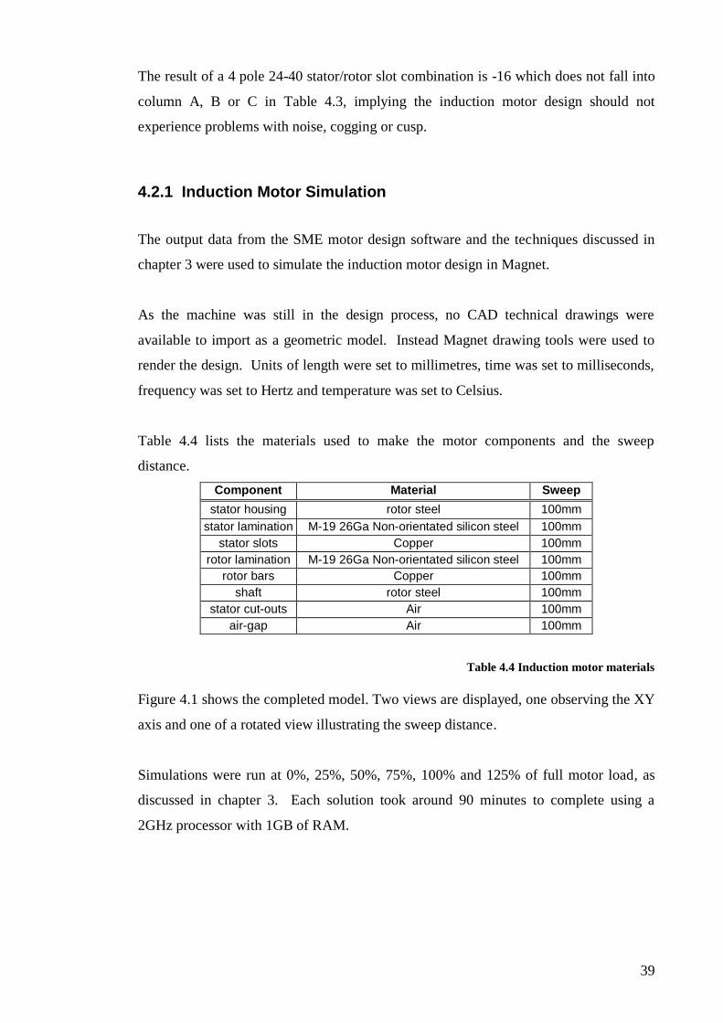
The result of a 4 pole 24-40 stator/rotor slot combination is -16 which does not fall into
column A, B or C in Table 4.3, implying the induction motor design should not
experience problems with noise, cogging or cusp.
4.2.1 Induction Motor Simulation
The output data from the SME motor design software and the techniques discussed in
chapter 3 were used to simulate the induction motor design in Magnet.
As the machine was still in the design process, no CAD technical drawings were
available to import as a geometric model. Instead Magnet drawing tools were used to
render the design. Units of length were set to millimetres, time was set to milliseconds,
frequency was set to Hertz and temperature was set to Celsius.
Table 4.4 lists the materials used to make the motor components and the sweep
distance.
Component Material Sweep
stator housing rotor steel 100mm
stator lamination M-19 26Ga Non-orientated silicon steel 100mm
stator slots Copper 100mm
rotor lamination M-19 26Ga Non-orientated silicon steel 100mm
rotor bars Copper 100mm
shaft rotor steel 100mm
stator cut-outs Air 100mm
air-gap Air 100mm
Table 4.4 Induction motor materials
Figure 4.1 shows the completed model. Two views are displayed, one observing the XY
axis and one of a rotated view illustrating the sweep distance.
Simulations were run at 0%, 25%, 50%, 75%, 100% and 125% of full motor load, as
discussed in chapter 3. Each solution took around 90 minutes to complete using a
2GHz processor with 1GB of RAM.

40
Figure 4.1 Completed induction motor model
4.2.2 Simulation Results
Table 4.5 displays the simulated motor efficiencies at the respective loads. Raw data
has been included in the Excel spread sheet entitled “induction motor testing” on the
attached CD.
Load (%)
Output Power (kW)
Input Power (kW)
Efficiency (%)
Power Factor
Speed (RPM)
Line Current
(A)
0 0 58.56 0 0.04 1494.84 4.17
25 249.49 328.47 75.96 0.18 1489.04 4.28
50 502.91 623.53 80.66 0.33 1477.68 4.73
75 752.77 887.25 84.84 0.47 1467.02 5.05
100 1005.91 1177.93 85.40 0.55 1455.41 5.65
125 1259.51 1459.57 86.29 0.62 1443.87 6.19
Table 4.5 Simulation results of induction motor
Figure 4.2 shows a graph of motor speed from start up to steady state under full load.
Start Up Speed
(At Full Load)
-500
0
500
1000
1500
2000
0 100 200 300
time (ms)
sp
eed
(rp
m)
Figure 4.2 Start-up characteristics of induction motor

41
Table 4.5 indicates an approximate efficiency of 85% under full load; however it is
important to recall the discrepancies between simulated and physical data discussed in
Chapter 3. Since the motor is modelled in only in two dimensions, Magnet does not
accurately account for all losses experienced within the machine. Stator end windings
and rotor end rings are not modelled in the simulation. Also, iron losses (hysteresis and
eddy currents) are not accurately accounted for in two dimensions. These points lead to
a consistent over estimation of efficiency in the motor simulation when compared to the
physical motor. The efficiencies listed in Table 4.5 are purely simulated values - it is
expected that the efficiency of the physical motor would be some percentage lower than
that listed. Whilst it may be possible to obtain more accurate analytical estimations
using other external modelling techniques, it was decided that the data gathered in
Magnet would be suitable for the purposes of this study.
4.3 PMSM Design
As discussed in chapter one, it is possible to design a PMSM which operates similarly
to a conventional synchronous motor with no damper or amortisseur windings installed
in the rotor. Although this design would theoretically be more efficient than
conventional induction motors or synchronous motors (the lack of rotor windings or
other forms of external rotor excitation should result in no rotor copper losses), there
would remain a requirement for an external controller to start and run the machine.
This external control system would usually require rotor position feedback leading to
the need for some form of rotor position encoder or resolver to be mounted on the rotor
shaft.
SME has had previous experience in the use of position sensors in submersible motors,
but have generally found them to be unreliable. Research therefore shifted to PMSMs
utilising sensor-less control. It was observed that a number of organisations are
working to achieve sensor-less vector control of PMSMs, however the technology is
still in the research stage and a great deal of work is required before a viable
commercial control system becomes available. Since one of the design goals of the
motor in this study is for high operating reliability, it was decided to design a PMSM
which has the ability to both start and run directly off a mains supply. By opting for this
design, complex external components to control the starting and running of the machine
are not required.

42
An added advantage of the line start PMSM is that the damper windings installed in the
rotor (in the form of a rotor cage) to allow line starting capabilities also work to increase
the machine’s stability. When operating at synchronous speed, the rotor turns at the
same speed as the stator rotating magnetic field. Since there is no relative motion
between the stator fields and the rotor, the induced voltage in the rotor cage is zero. If
the machine is suddenly loaded, causing the rotor to turn slower than the stator field,
voltage is induced in the rotor cage producing a flow of current. This induced current
flow produces a magnetic field which interacts with the stator magnetic field to create a
torque that tends to increase rotor speed. Similarly, should the rotor turn faster than the
stator field, a torque is induced which tends to slow the machine down (Chapman, 2005
pg 371). This phenomenon tends to dampen the effect of sudden load changes and
other transients on the machine.
4.3.1 Rotor Design
Based on the six inch induction motor discussed in section 4.2, a line start PMSM was
designed. The rotor was modified by altering the rotor laminations and rotor bars in
order to accommodate the added permanent magnets. The rotor shaft diameter was
designed to be smaller than normal so as to allow greater area in the rotor lamination for
the mounting of permanent magnets. The stator housing and windings remained
identical so that direct comparisons could be made between the efficiencies of the two
machines operating with different rotors.
4.3.1.1 Rotor Design Selection
Since a line start PMSM requires a rotor cage to facilitate line starting, the motor
configuration is limited to the interior mounted magnet type introduced in section 1.1.1.
The interior PMSM is a more complex design than the surface mounted type (where the
magnets are simply glued to the rotor circumference), however the physical nature of
the rotor provides some mechanical protection to the magnets.
Figure 4.3 illustrates two basic examples of magnet mounting configurations in an
interior PMSM rotor. The rotor on the left is an example of a radially magnetised rotor
and on the right a circumferentially magnetised rotor. The naming convention relates to
the direction of the magnetic fields produced by the magnets (indicated in Figure 4.3 by

43
the blue arrows coming out of the magnet material). Other rotor configurations are
possible, some of which lack rotational symmetry and others which are hybrid
combinations of the radial and circumferential designs. For this study, it was decided
to opt for the circumferentially magnetised rotor. Research has indicated that this
design has a greater potential to increase efficiency than the radial geometry design
(Chaudhari, Pillai and Fernandes, 1998), however it does require a non-magnetic shaft.
Figure 4.3 Radially magnetised (A) and circumferentially magnetised rotor (B)
4.3.1.2 Rotor Design Testing
Finite element analysis was used to find the optimum design of the rotor. The initial
PMSM rotor model was based on the induction rotor discussed in section 4.2. Twelve
rotor bars were removed (to allow insertion of the magnets) and replaced with four solid
copper bars. Four neodymium iron boron (Nd2Fe14B) magnets were added to the model
and magnetised in the direction indicated in Figure 4.3 B. Magnet simulations were
then used to observe the performance of the design when modifying the dimensions
indicated by arrows in Figure 4.4.

44
Figure 4.4 PMSM rotor model dimensions tested
Results of the simulations may be found in the Excel spreadsheet entitled “rotor testing”
on the attached CD. Approximately fourteen different designs were tested for their
starting performance and ability to synchronise under full load. It was observed that the
magnet dimensions directly affected power factor and speed characteristics. A larger
magnet area led to greater rotor excitation, ultimately improving a lagging power factor
to the point where the power factor became leading. A consequence of using a larger
magnet area or stronger magnet material, however, is an increase in the braking torque
produced by the magnets. This braking torque must be overcome by asynchronous
torque to allow the motor to accelerate up to synchronous speed. Based on the results of
the various designs tested, the best performing dimensions were used to further refine
the rotor.
4.3.1.3 Final Rotor design
The optimum design found in section 4.3.1.2 was purely theoretical and modifications
were required so that the rotor would be practically viable to build. These modifications
included making allowances for:
anchoring the magnets in place
mounting of rotor laminations (which were modelled in four separate quarters as
indicated in Figure 4.4), and
availability of suitable materials, including a non-magnetic material for the rotor
shaft.
The results of these modifications are shown in Figure 4.5 which is presented as the
final rotor design. The rotor bars are of the same dimension as the induction motor
designed in section 4.2 to reduce manufacturing costs. The end caps are solid copper
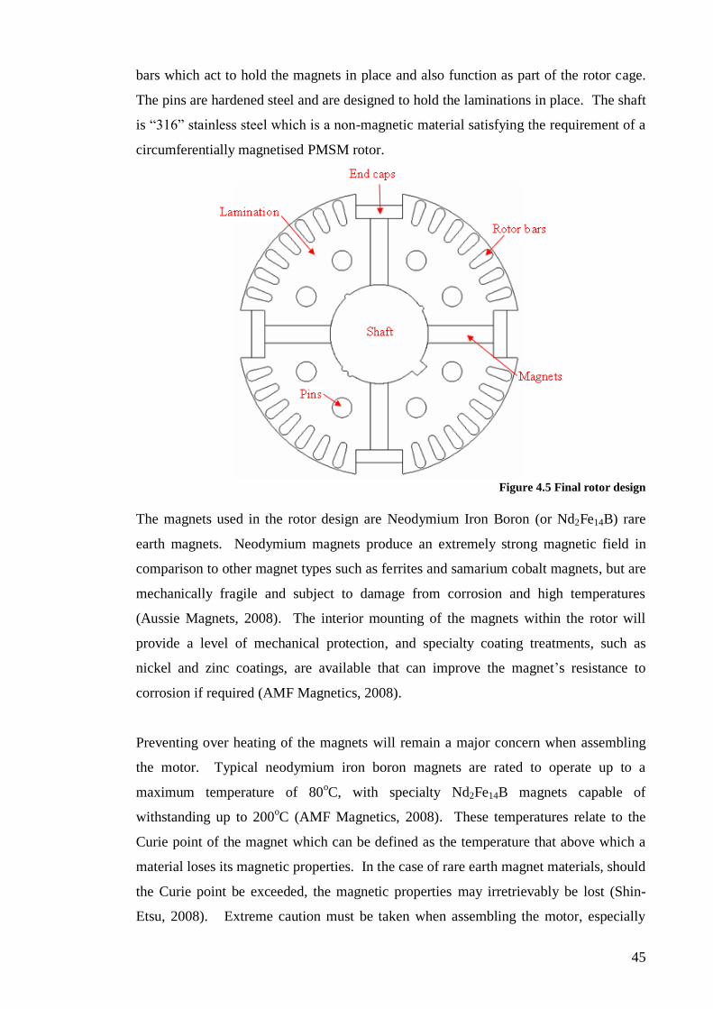
45
bars which act to hold the magnets in place and also function as part of the rotor cage.
The pins are hardened steel and are designed to hold the laminations in place. The shaft
is “316” stainless steel which is a non-magnetic material satisfying the requirement of a
circumferentially magnetised PMSM rotor.
Figure 4.5 Final rotor design
The magnets used in the rotor design are Neodymium Iron Boron (or Nd2Fe14B) rare
earth magnets. Neodymium magnets produce an extremely strong magnetic field in
comparison to other magnet types such as ferrites and samarium cobalt magnets, but are
mechanically fragile and subject to damage from corrosion and high temperatures
(Aussie Magnets, 2008). The interior mounting of the magnets within the rotor will
provide a level of mechanical protection, and specialty coating treatments, such as
nickel and zinc coatings, are available that can improve the magnet’s resistance to
corrosion if required (AMF Magnetics, 2008).
Preventing over heating of the magnets will remain a major concern when assembling
the motor. Typical neodymium iron boron magnets are rated to operate up to a
maximum temperature of 80oC, with specialty Nd2Fe14B magnets capable of
withstanding up to 200oC (AMF Magnetics, 2008). These temperatures relate to the
Curie point of the magnet which can be defined as the temperature that above which a
material loses its magnetic properties. In the case of rare earth magnet materials, should
the Curie point be exceeded, the magnetic properties may irretrievably be lost (Shin-
Etsu, 2008). Extreme caution must be taken when assembling the motor, especially

46
when the rotor bars are brazed (welded) to the copper end rings. Techniques such as
immersing the rotor assembly in water during the welding process will need to be
adopted to minimize the magnet’s exposure to excessive heat.
As shown in Figure 4.5, the rotor laminations consist of four separate pieces locked
together with hardened steel pins. The permanent magnets are butted up against the
non-magnetic shaft and are held in the slots with solid copper bars. In order to hold the
pins and copper end bars in place and to hold the entire rotor assembly together, steel
spacers were designed to sit at either end of the rotor stack between the rotor
laminations and the end rings. Figure 4.6 displays the rotor spacer and the complete
rotor assembly; further technical drawings may be found in the attached CD.
Figure 4.6 Rotor spacer and complete rotor assembly
As discussed in chapter 3, the Magnet software used in this study cannot model objects
in three dimensions. Therefore, it was not possible to use Magnet to model the effects
the spacers may have on motor operation. It is not foreseen that they will have any ill-
effects on the physical motor’s performance.
4.3.2 PMSM Simulation
Similar to the induction motor simulation in section 4.2.1, no CAD technical drawings
were available to import as a geometric model. Therefore, Magnet drawing tools were
again used to render the design. Units of length were set to millimetres, time was set to
milliseconds, frequency was set to Hertz and temperature was set to Celsius.

47
Table 4.6 lists the materials used to make the motor components and the sweep
distance. Note that the non-magnetic “316” stainless steel to be used as the physical
motor shaft was not available in Magnet’s materials database. Instead non magnetic
aluminium was used in the simulations.
Component Material Sweep
stator housing rotor steel 100mm
stator lamination M-19 26Ga non-orientated silicon steel 100mm
stator slots copper 100mm
rotor lamination M-19 26Ga non-orientated silicon steel 100mm
rotor bars Copper 100mm
end cap Copper 100mm
magnets neodymium iron boron 100mm
shaft aluminium 100mm
stator cut-outs air 100mm
air-gap air 100mm
Table 4.6 PMSM materials
Figure 4.7 shows the completed model. Two views are displayed, one observing the XY
axis and one of a rotated view illustrating the sweep distance.
.
Figure 4.7 Completed PMSM model
Simulations were run to ensure the motor could self start at all initial rotor positions.
The motor was then load tested at 0%, 25%, 50%, 75%, 100% and 125% of full motor
load (as discussed in chapter 3) with the initial rotor position being set to the “worst
case” position found in the first tests. As discussed by Libert, Soulared and Engstrom
(2002), the initial rotor position of the PMSM greatly affects the starting performance of
the motor. This arises from the fact that the permanent magnets in the rotor provide a
braking torque prior to start up, which varies according to rotor position. The motor

48
was also tested for starting performance on a reduced supply voltage and with a higher
starting inertia. Each solution took around 90 minutes to complete using a 2GHz
processor with 1GB of RAM.
4.3.3 Simulation Results
The speed curves of the best and worst cases of initial rotor positions are illustrated in
Figure 4.8. The motor was simulated running at full load. Raw data may be found in
the Excel spreadsheet entitled “final design testing” on the attached CD.
Initial Rotor Position Best and Worst Case
Start-up Speed
-1000
-500
0
500
1000
1500
2000
2500
1 101 201 301 401 501
time (ms)
sp
ee
d (
rpm
)
Worst Case
Best Case
Figure 4.8 PMSM rotor speed - best and worst case initial rotor position
Figure 4.9 illustrates the transient starting current with the rotor initially in the best and
worst case positions. Note that once steady-state is reached both currents become equal.
Initial Rotor Position Best and Worst Case
Line Current
-60
-40
-20
0
20
40
60
80
100
120
1 101 201 301 401 501
time (ms)
cu
rre
nt
(A)
Worst Case
Best Case
Figure 4.9 PMSM rotor current - best and worst case initial rotor position

49
Table 4.7 and Figure 4.10 display the results of the PMSM simulation at 0, 25%, 50%,
75%, 100% and 125% load. Included, for comparison, is the data taken from the 6 inch
induction motor simulated in section 4.2.2.
Induction motor data is displayed in red
Load (%)
Output Power
(W)
Input Power
(W)
Efficiency (%)
Power Factor
Speed (RPM)
Line Current
(A)
0 0 0 126.31 58.56 0 0 0.62 0.04 1500.75 1494.84 0.54 4.17
25 249.97 249.49 258.54 328.47 96.69 75.96 0.82 0.18 1499.83 1489.04 0.83 4.28
50 499.98 502.91 508.74 623.53 98.28 80.66 0.95 0.33 1499.94 1477.68 1.40 4.73
75 749.29 752.77 750.72 887.25 99.81 84.84 0.97 0.47 1500.05 1467.02 2.02 5.05
100 1000.14 1005.91 1015.23 1177.93 98.51 85.40 0.99 0.55 1500.21 1455.41 2.69 5.65
125 1250.27 1259.51 1276.22 1459.57 97.97 86.29 0.99 0.62 1499.90 1443.87 3.37 6.19
Table 4.7 PMSM versus induction motor under load
Output Power
0
200
400
600
800
1000
1200
1400
0 25% 50% 75% 100% 125%Load (%)
Po
wer
(kW
)
Input Power
0.0
200.0
400.0
600.0
800.0
1000.0
1200.0
1400.0
1600.0
0 25% 50% 75% 100% 125%
Load (%)
Po
we
r (k
W)
Efficiency
0
20
40
60
80
100
120
0 25% 50% 75% 100% 125%Load (%)
Eff
icie
ncy (
%)
Power Factor
0.00
0.20
0.40
0.60
0.80
1.00
1.20
0 25% 50% 75% 100% 125%
Load (%)
Po
wer
Facto
r
Speed
1400.0
1420.0
1440.0
1460.0
1480.0
1500.0
1520.0
0 25% 50% 75% 100% 125%Load (%)
Sp
eed
(rp
m)
Current
0.00
1.00
2.00
3.00
4.00
5.00
6.00
7.00
0 25% 50% 75% 100% 125%Load (%)
Cu
rren
t (A
)
Figure 4.10 PMSM versus induction motor under load

50
Figure 4.11 displays the PMSM’s ability to synchronise a full load with a reduced
supply voltage.
Starting Performance - Different Values
of Supply Voltage
-1000
-500
0
500
1000
1500
2000
1 101 201 301 401 501
time (ms)
sp
eed
(rp
m)
Full Voltage
85% Full Voltage
75% Full Voltage
Figure 4.11 Starting performance of PMSM with reduced supply voltage
Figure 4.12 displays the PMSM’s ability to synchronise with increased values of
starting inertia (J).
Starting Performance - Different Values
of Rotor Inertia (J)
-1000
-500
0
500
1000
1500
2000
1 101 201 301 401 501
time (ms)
sp
eed
(rp
m) J
J x 2.5
J X 5
Figure 4.12 Starting performance of PMSM with increased starting inertia

51
The motor speed and the rotor position should no squirrel cage be fitted to the rotor are
displayed in Figure 4.13 and 4.14, respectively. These results demonstrate the
importance of the squirrel cage.
Motor Speed - no rotor bars
-500
-400
-300
-200
-100
0
100
200
300
400
500
0 50 100 150 200 250 300 350
time (ms)
sp
eed
(R
PM
)
Figure 4.13 Speed characteristic of PMSM with no rotor bars
Rotor Position - no rotor bars
-10
-5
0
5
10
15
20
25
30
0 50 100 150 200 250 300 350
time (ms)
Po
sit
ion
(D
eg
)
Figure 4.14 Rotor position of PMSM with no rotor bars
4.4 Discussion
Prior to discussing the performance of the induction motor and the PMSM it is
important to first address the accuracy of the modelling techniques. As has been stated
previously, Magnet only models motors in two dimensions and therefore does not
include the end components of the motor assemblies, nor does it fully account for iron

52
losses. For the purpose of this study, these omissions were not considered a large issue
as the error present in one model (i.e. the induction motor) is also present in the other
(the PMSM). Although the magnitudes of values calculated in the two models may be
slightly incorrect, the difference between the two would remain basically the same. The
values reported in Table 4.5 and Table 4.7 are simulated results only. It is expected that
each physical motor’s measurements will differ slightly, as discussed in chapter 3.
Most importantly, the efficiencies quoted in the tables are expected to be somewhat
higher to that measured in the physical machines.
4.4.1 Six Inch Induction Motor
The six inch induction motor was successfully simulated in Magnet. The results
displayed no indications of cogging or cusp problems meaning the stator slot/rotor bar
combination was correct, as predicted in Section 4.2. The simulated motor was capable
of supplying full load power at a full load slip of approximately 3 percent.
As shown in Table 4.5, the power factor of the induction motor at little and no loads is
very low. This is a common phenomenon in induction motors and is a direct result of
the magnetizing current required to excite the machine. In order to generate a rotating
magnetic field, an induction motor draws current which is consumed as reactive power.
Power factor can be defined as the ratio of real power over apparent power, and
apparent power is the multiple of phase voltage and current. Therefore, if a machine is
consuming reactive power, current draw is increased and so too is apparent power.
Consequently, at lighter loads an induction motor consumes less real power in relation
to apparent power, which ultimately results in a lower power factor.
The efficiency of the induction motor at all loads is not high, however it is acceptable
for a motor of this size and capacity class. No attempts have been made to further
improve the efficiency of the machine as this study is primarily focused on the benefits
of adopting a permanent magnet rotor.
The design process for the six inch induction motor is complete. Full technical
drawings for the motor can be found in the attached CD. As the motor is a prototype
and is not expected to run for extended periods no allowances for heat exchange (such
as incorporating a fan on the rotor shaft) have been made. Note that at the time of

53
writing, the major motor components were on order from China. Once the remainder of
the parts were obtained, the motor will be assembled locally at SME in Maddington.
4.4.2 Six Inch PMSM
The six inch PMSM was successfully simulated in Magnet. Figure 4.9 highlights the
considerable difference in starting currents between the best and worst case initial rotor
positions during the transient period from start up until steady state. This difference
arises from the braking torque provided by the permanent magnets which must be
overcome by the motor. Depending on the embedded permanent magnet’s orientation
with the stator lamination, particularly the stator teeth, the force required to move the
rotor changes. As discussed by Miller in 1984, if a PMSM is poorly designed, braking
torque can be so extreme as to prevent the motor from starting and achieving
synchronous speed. However, the simulation results in this case indicated that the
machine could line start and synchronise under full load from all initial rotor positions.
Figure 4.13 and 4.14 illustrate the importance of the rotor squirrel cage. These graphs
were obtained by removing the rotor bars from the PMSM and simulating the modified
design in Magnet. As can be seen in the graphs, the rotor velocity oscillates backwards
and forwards between positive and negative values, and never stabilises to a constant
(synchronous) speed. To explain this action, when power is applied to the machine, the
stator magnetic fields begin rotating at synchronous speed around the motor. Since the
rotor of the PMSM is not physically capable of instantly accelerating to synchronous
speed, the rotor will tend to vibrate backwards and forwards as shown in Figure 4.14.
The average torque induced on the shaft of the rotor is zero over one complete electrical
cycle, and the motor will continue to oscillate indefinitely. In the case of a physical
motor, the machine will eventually overheat and fail (Chapman, 2005, pg 366).
As discussed in chapter 1, two options are available to allow the PMSM to start.
Firstly, a variable voltage variable frequency (VVVF) drive could be used to slow the
stator magnetic field (by reducing the electrical frequency) to a speed that the rotor can
accelerate and lock in with during one half cycle of the magnetic field’s rotation
(Chapman, 2005, pg 366). A consequence of operating the PMSM at a slower speed
however, is that the internal generated voltage will be lower than normal. If the
terminal, or line voltage, remains at the same normal level, current levels in the stator

54
become dangerously high. Therefore the VVVF drive must roughly vary the line
voltage linearly with applied frequency (Chapman, 2005, pg 367). After starting, the
VVVF drive can control motor speed by ramping up or down applied frequency (and
line voltage).
The second method for motor starting is to use damper windings in the rotor which
allow for line starting. The rotor starts asynchronously and locks into synchronism when
motor speed nears synchronous speed. The benefit of this design is that there is no
costly drive hardware or rotor position feedback required to operate the motor. For
these reasons the line start PMSM design was adopted in this study. Magnet
simulations displayed graphically in Figure 4.10 suggest that the machine is capable of
line starting and achieving synchronous speed over a range of mechanical loads. The
disadvantage of this design, however, is the lack of speed control in the motor. A
VVVF drive would still be required if the motor needed to be run at variable speeds.
This limitation was not considered important in the study as it is intended to run the
motor at a fixed speed to operate a multi-stage pump.
Figure 4.11 demonstrates the machine’s ability to start and run on a reduced voltage
supply. It can be seen that the machine can synchronise down to a line voltage of
approximately 75% of full voltage. This is an important feature in the motor as,
pending design approvals, the PMSM may be operated in remote areas where the local
voltage supply may be weak. Similarly, the PMSM may be installed deep in a bore-
hole where the length of supply cables may introduce a voltage drop which would
reduce the terminal voltage at the motor.
Figure 4.12 demonstrates the machine’s ability to start and synchronise with a higher
value of initial starting inertia. Magnet automatically calculates the starting inertia
based on the materials specified and the dimensions and shape of the design. Since only
2D simulations were run, it is not possible to simulate the coupling of a pump to the
machine which may affect the starting inertia. Instead, simulations were run where the
inertia was manually set to values higher than the Magnet calculated value. Simulations
indicate that the motor can start and run with a starting inertia five times greater than
that calculated (5 x 0.00393kg.m2).

55
Table 4.7 and Figure 4.10 compare the results of the PMSM and the induction motor at
0%, 25%, 50%, 75%, 100% and 125% load. The results indicate that, for an almost
identical power output, the efficiency of the PMSM is consistently higher than the
induction motor at all loads with the exception of no load conditions. Whilst real power
consumed by the induction motor at no load is low, the current drawn by the machine is
high as the machine absorbs reactive power to maintain the rotating magnetic fields (as
discussed previously). Figure 4.10 illustrates the difference in line current drawn by the
two machines. The PMSM draws approximately eight times less current than the
induction motor at no load, and nearly half the current at full load. As expected, the
PMSM maintains synchronous speed at all loads, whilst the induction motor exhibits an
approximate 3% slip at full load. The PMSM maintains an almost consistently higher
power factor than the induction motor. This is indicative of the higher efficiency of the
machine.
The results of the simulation suggest that a physical PMSM of this design would start
and run successfully and would be considerably more efficient than a similar sized
induction motor. The design process for the PMSM has been finalised and a complete
set of technical drawings for the motor can be found in the attached CD. As with the
induction motor, no fan has been integrated into the rotor design. It is not expected that
the physical motor would be run for long periods - it will simply be used to gain
efficiency measurements to compare with the induction motor. Note that at the time of
writing, the prototype motor components were on order and construction was expected
to begin pending their arrival at SME.

56
5 CONCLUSION AND FUTURE WORK
5.1 Conclusion
The aim of this thesis was to design a three phase electric motor suitable for use in
submersible pumping applications. High reliability and efficiency were paramount in
the design as it is intended to operate the motor in remote areas powered from a
photovoltaic supply. Before producing a fully working submersible motor, it was
initially decided to design a prototype to ensure the ideas developed in this study would
be feasible and that the design would be viable. A prototype conventional 1kW
induction motor and a high efficiency permanent magnet synchronous motor were
designed and simulated using the Magnet software.
Prior to designing the motors, the accuracy and suitability of Magnet were verified by
modelling an existing SME machine. A previously built 10 inch, 230kW induction
motor was physically tested to measure its operating characteristics over a range of
loads. The motor design was then simulated in Magnet over identical loads. The results
from the physical testing and from the simulation were then compared. It was observed
that Magnet accurately predicted the operating characteristics of the physical machine
within a set of certain limitations. Firstly, the Magnet software used in this study only
modelled designs in two dimensions. This introduced errors in the results by neglecting
the motor end components (rotor end rings and stator end windings). Secondly, the
Magnet transient solver did not accurately account for iron core losses (hysteresis and
eddy current losses). Finally, Magnet modelled components and materials as “ideal”
and did not account for impurities and other uncertainties present in physical motors.
Despite these deficiencies, it was found that Magnet was a powerful tool for use in the
design and simulation of motors. The error present in the simulated results was small
compared to the physical results and was deemed acceptable for future motor design.
A conventional 6 inch 1kW induction motor was designed to provide a reference for
efficiency levels before designing the PMSM. The induction motor was a wye
connected four pole machine rated to 1kW with an operating voltage of 220V line-to-
line at a frequency of 50Hz. The stator consisted of 24 stator slots wound in a full coil
arrangement with 54 turns per slot. The rotor consisted of 40 solid copper rotor bars
connected in parallel at either end of the rotor by copper end-rings. Magnet simulations

57
indicated a full load efficiency of 85% (neglecting iron losses and other losses arising
from a 2 dimensional analysis), power factor of 0.55 (lagging) and a motor slip of
approximately 3%.
Based on the induction motor, a PMSM was designed with an identical stator assembly
and a modified rotor. Four neodymium iron boron permanent magnets, arranged in a
circumferentially magnetized layout, were installed in the rotor. Damper windings were
also fitted to allow for line starting and line operation. These windings negated the
requirement for costly control hardware and added a degree of machine “stability” when
operating under a variable load. It was found, through simulations, that the PMSM was
approximately 13% more efficient than the conventional induction motor when
operating at full load. Full load power factor was 0.99 and speed remained at
synchronous speed. Simulations indicated that the motor would successfully line start
and synchronise from all initial rotor positions down to a reduced line voltage of 75% of
normal line voltage. Based on the positive results obtained through simulations, it was
decided that it would be economically viable to produce a working prototype of the
PMSM for further, practical, testing.
5.2 Future Work
A number of important steps are required before producing a commercially viable
submersible PMSM. Most importantly, the electrical designs discussed in this study
must be verified by constructing and testing the physical motors. At the time of writing,
parts for both motors were being procured from China and locally in Maddington and
construction was expected to begin soon after their arrival.
The original design specifications called for a 4 inch motor to operate at 1700rpm.
Instead, a 6 inch prototype was designed as the larger size would make construction
easier – particularly the installation of the permanent magnets. The analytical and
practical techniques learnt from this study could then be used to design a smaller 4 inch
machine. The complexity in the design will be fitting a rotor cage and the magnets into
a smaller diameter rotor. Practically, construction of a smaller rotor will be difficult as
the strength of the rare earth permanent magnets is such that extra care must be taken
when they are in close proximity with each other. It is recommended that assembly of
the machine be done in a “clean room” which will minimise the risk of contamination of
58
foreign metal particles being attracted to the magnets. Similarly, the prototype model
was designed to operate at 1500 rpm to allow direct connection to 50Hz mains. The
final motor design will need to be optimised for operation at approximately 57 Hz.
Physical testing of such a machine will require a variable frequency device. SME
currently owns a 350kVA generator capable of operating from 50 to 60HZ which would
be suitable for testing the motor.
Depending on the success of the final prototype, work can commence on the
design/sourcing of a suitable photovoltaic power supply and high efficiency pump. This
includes sourcing items such as the solar panels, inverters, controllers and battery back-
up options. Research will need to be conducted to investigate the feasibility of
producing a generic “off the shelf” kit consisting of the motor, pump, solar panels and
all ancillary control equipment or whether it would be more cost effective to produce
tailor made packages for individual applications. This decision will come down to the
target market and their individual requirements, including factors such as water demand,
existing power infrastructure, periods of required water usage and, importantly, budget.
Finally, PMSM technology has far wider applications than use in submersible motors
alone. The main finding of this study (in agreement with the findings of previous work
reviewed in the literary study) indicated that PMSMs offer greater operating efficiencies
than similar sized conventional induction motors. It is also expected that the line start
PMSM will offer high reliability as no added complex control hardware is required to
operate the machine. These points make the line start PMSM highly suited for many
applications. As the public demand for more power efficient machines increase,
PMSMs will have an increasing role in both industrial and domestic markets.

59
6 REFERENCES
AMF Magnetics, online resource accessed 16th
October 2008 from,
www.amfmagnetics.com.au
Arroyo E.L.C, “Modelling and Simulation of Permanent Magnet Synchronous Motor
Drive System” University of Puerto Rico Mayaguez Campus, 2006
Aussie Magnets, online resource accessed 13th
October 2008 from,
http://aussiemagnets.com.au/info.php?section=rareearth
Boldea I and Nasar S.A, Electric Drives 2nd
Edition, Taylor and Francis Group, 2006.
Chapman S.J, Electric Machinery Fundamentals 4th
Edition, McGraw Hill, 2005
Chaudhari B.N, Pillai S.K and Fernandes B.G, “Energy Efficient Line Start Permanent
Magnet Synchronous Motor,” IEEE Region 10 International Conference on
Global Connectivity in Energy, Computer, Communication and Control, vol. 2,
pp. 379-382, 1998
Dehkordi A.B, Gole A.M and Maguire T.L, “Permanent Magnet Synchronous Machine
Model for Real- Time Simulation,” International Conference on Power Systems
Transients (IPST’05), paper number IPST05-159, 2005
Dorf R.C and Svoboda J.A, Introduction to Electric Circuts 6th
Edition, John Wiley and
Sons, 2004
Electrical Apparatus Service Association (EASA), AC Motor Redesign, Electrical
Apparatus Service Association, Inc., St. Louis, Missouri, 1990
Fitzgerald A.E, Kingsley C, Umans S. D, Electric Machinery 6th
Edition, McGraw Hill,
2003.
Haffenden R, Personal communication on 6th
August 2008, Submersible Motor
Engineering, 2008
Henneberger S, Van Haute S, Hameyer K and Belmans R, “Submersible Installed
Permanent Magnet Synchronous Motor for a Photovoltaic Pump System,” IEEE
International Electric Machines and Drives Conference Record, pp. WB2/10.1-
WB2/10.3, 1997
Hitachi Industrial Equipment Systems Co., online resource accessed 19th
September
2008 from, www.hitachies.co.jp/english/products/motor/submersible/can/
features.htm
Ho S.L and Fu W.N, “Application of Automatic Choice of Step Size for Time Stepping
Finite Element Method to Induction Motors,” IEEE Transactions on Magnetics,
vol. 33, no. 2, pp. 1370-1373, 1997.
Infolytica Corporation, Magnet Version 6.23, Getting Started Guide. PDF attached to
help files with the Magnet program software, 2007
Libert F, Soulard J and Engstrom J, “Design of a 4-pole Line Start Permanent Magnet
Synchronous Motor,” Proceedings of International Conference on Electrical
Machines (ICEM’02), Belgium August 25-28, 2002
Miller T.J.E, “Synchronization Of Line-Start Permanent Magnet AC Motors,” IEEE
Transaction On Power Apparatus And Systems, vol. PAS-103, no. 7, July 1984

60
Minimum Energy Performance Standards (MEPS), Australian Government Department
of the Environment , Water, Heritage and the Arts; online resource accessed
23rd
September 2008, from www.energyrating.gov.au/library/details200214-
motors.html
Pillay P, Krishnan R, “Modeling of Permanent Magnet Motor Drives,” IEEE
Transactions on Industrial Electronics, vol. 35, pp. 537-541, 1988
Ramsden V.S, Watterson P.A, Hunter G.P, Zhu J.G, Holliday W.M, Lovatt H.C, Wu W,
Kalan B.A, Collocott S.C, Dunlop J.B, Gwan P.B and Mecrow B.C, “High-
performance Electric Machines for Renewable Energy Generation and Efficient
Drives,” Renewable Energy, vol. 22, pp. 159-167, 2001.
Say M.G, Alternating Current Machines 4th
Edition, Pitman Publishing Ltd, 1976.
Sebastian T, Slemon G.R, and Rahman M.A, “Modelling of Permanent Magnet
Synchronous Motors,” IEEE Transactions on Magnetics, vol. 22, pp. 1069-
1071, 1986.
Shin-Etsu, online resource accessed 16th
October 2008 from, www.shinetsu-rare-earth-
magnet.jp/e/
SME, online resources accessed 15th
September 2008 from, www.smeng.com.au
Standards for Energy Efficiency of Electric Motor Systems (SEEEM), online resource
accessed 23rd
September 2008, from www.seeem.org
Wu R and Slemon G.R, “A Permanent Magnet Motor Drive Without a Shaft Sensor,”
IEEE Transactions on Industry Applications, vol. 27 no. 5, pp.1005-1011, 1991

61
APPENDIX A- Attached Multimedia
The CD attached to this thesis contains the following contents:
Full text copy of the thesis
Excel spreadsheets (contained in the relevant chapter folders) displaying raw
data and calculations of various tests discussed in the text
Technical drawings of the designed induction motor and the PMSM
Magnet motion animation clips. These include examples of two, four and six
pole induction motors accelerating from stand-still to steady state, a motor
having full load applied, and an animation of the permanent magnet
synchronous motor designed in this report. The clips are saved as “.AVI” files
and should open in Microsoft Media Player or most other types of media
players.

62
APPENDIX B- Test Motor
Figure B.1 Test motor rotor lamination (SME, 2008)
Figure B.2 Test motor stator laminations (SME, 2008)

63
Figure B.3 Test motor outline drawing (SME 2008)

64
Figure B.4 Test motor stator winding layout (SME, 2008)

65
The following is a copy of the performance data sheet of the 10” submersible motor
used for Magnet simulations. This data was obtained on the 29th
August, 2008, by
physical testing in the SME workshop.

66
APPENDIX C- Calculations
Data obtained from Magnet for voltages and current are magnitudes not RMS values.
To calculate the RMS values, one cycle of data was obtained and the following
equations were used:
2/1
0
2
2/1
0
2
)(1
)(1
T
rms
T
rms
dttiT
I
dttvT
V
Where:
Vrms = rms voltage
Irms = rms current
v(t) = instantaneous voltage
i(t) = instantaneous current
T = period
Input real power is not calculated directly in Magnet. The following equations have
been used based on input voltages and currents:
T
dttpT
P0
)(1
Where:
P = average power
p(t) = instantaneous power = v(t)i(t)
T = period
Output power is calculated based on values of torque and speed using the following
equation:
P
Where:
P = power
τ = Torque
ω = angular velocity (rad/s)
Power factor has been calculated based on input real power and input apparent power.
The following equation was used:
rmsrms IV
P
S
Ppf
Where:
Pf = power factor
|S| = apparent power

67
The efficiency of the Magnet simulations has been calculated using the ratio of output
power to input power as shown in the following equation:
%100in
out
P
P
Where:
η = efficiency
The slip of an induction motor can be calculated using the ratio of slip speed to
synchronous speed of the machine as shown in the following equation:
%100%100
sync
msync
sync
slip
n
nn
n
ns
And:
P
fnsync
120
Where:
s = slip
nslip = slip speed (rpm)
nsync = speed of magnetic fields (rpm)
nm = mechanical speed (rpm)
f = electrical frequency (Hz)
P = machine poles

68
APPENDIX D- PMSM Design
The following is a copy of the results of the design of the 6 inch induction motor using
the design software at SME.

69
Model: #6" 1kW 4P 220V 50Hz ,Oil filled motor(02 09 08)

70
Figure D.1 Six inch induction motor- general arrangement

71
Figure D.2 Six inch PMSM- general arrangement