design of a hands free control system for physical...
TRANSCRIPT

Design of a Hands Free Control System for Physical Manipulation
Preliminary Project Report
Kassidy Kenney
Angelo Huan
Kimberly Harrington
Muhammad Sungkar
Faculty Advisor: Dr. Sherry
Project Sponsor: General Dynamics, Mike DeMichele
Department of Systems Engineering & Operations Research George Mason University 4400
University Drive, Fairfax VA 22030 April 22, 2015

1
Abstract
Virtually all devices require a physical control interface to translate an operator’s intentions to
the functioning of that device. The driver of a car is wholly dependent upon his ability to
physically manipulate a steering wheel; the operation of a computer is reliant on a user’s ability
to maneuver a keyboard and mouse. The steering wheel, keyboard and mouse are all examples of
human-machine interfaces which may be inoperable by physically disabled persons who lack the
ability to physically manipulate objects. Based upon this need, the project aims to create an
accurate, reliable, and versatile hands-free control interface. When applied to existing devices,
this control interface has the potential to substantially improve the independence, capabilities and
quality of life for disabled persons.
Brain-machine interfaces eliminate the need for a physical controller. These interfaces derive a
control system directly from the user’s thoughts, rather than translating them through a physical
interface. Currently, the front running brain-machine interface employs electroencephalography
technology, which measures electrical pulses generated from a user’s brain. The project team
will employ this technology to ultimately replace traditional control systems with a hands-free
alternative.

2
Contents
1.0 Context
1.1 Interfaces
1.1.1 Human Machine Interfaces
1.1.2 Brain Machine Interfaces
1.2 Electroencephalography
1.2.1 Technology
1.2.2 Current Uses
1.2.3 Emotiv
1.3 Physically Disabled Persons and Associated Challenges
2.0 Stakeholders
2.1 The Handicapped:
2.2 EEG control system users:
2.3 Insurance Companies:
2.4 Industries:
2.5 Government:
2.6 Stakeholder Tension:
3.0 Problem Definition
3.1 Gap Definition
3.2 Problem Statement
3.3 Need Statement
3.4 Win-Win
4.0 Concept of Operation

3
4.1 Virtual Simulation and Necessary Controls
4.2 System Boundary Diagram
4.3 Requirements
4.3.1 Mission Requirements
4.3.2 Functional Requirements
4.3.3 Technology Requirements
5.0 Project Plan
5.1 SOW
5.2 WBS
5.3 Schedule
5.4 Critical Path Analysis
5.5 Project Risk Mitigation
5.6 Planned Budget
Works Cited

4

5
1.0 Context
This section will provide insight into current control system methodology, the existing
technology that will be applied to the project and information gathered from related research.
The purpose of this section is to identify the design space of the project, as well as to understand
relevant works.
Note: Technology Readiness Level
This project aims to advance EEG technology and its applications. The outcomes of this project
may create an argument to increase the funding and focus on EEG technology. That being said,
many of the technologies, especially in regards to EEG data collection still being developed.
This project will be performed at a Technological Readiness level 3, as defined in the DoD TRL
Definitions, Descriptions and Supporting Information Table. This table has been attached as
Appendix 2.
1.1 Interfaces
1.1.1 Human Machine Interfaces
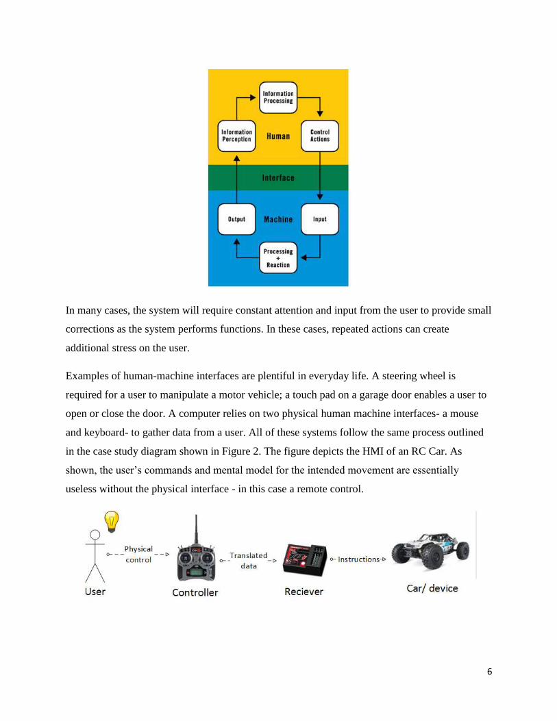
A Human-Machine Interface (HMI) is any interface facilitating interaction between human and
machine. HMIs have greatly advanced since the beginnings of computing. Original HMIs were
driven by single-selection menus. Since then, HMI has progressed to mouse/keyboard-controlled
interfaces, and now to touch screen interfaces.
Figure 1 displays the cyclic nature of HMIs. As shown in Figure 1, the system is driven by user
input. The human user, however is entirely reliant on the HMI to provide input to the system.
6
In many cases, the system will require constant attention and input from the user to provide small
corrections as the system performs functions. In these cases, repeated actions can create
additional stress on the user.
Examples of human-machine interfaces are plentiful in everyday life. A steering wheel is
required for a user to manipulate a motor vehicle; a touch pad on a garage door enables a user to
open or close the door. A computer relies on two physical human machine interfaces- a mouse
and keyboard- to gather data from a user. All of these systems follow the same process outlined
in the case study diagram shown in Figure 2. The figure depicts the HMI of an RC Car. As
shown, the user’s commands and mental model for the intended movement are essentially
useless without the physical interface - in this case a remote control.

7
These interfaces are largely successful for users with full control of motor functions. However,
the loss of motor function leaves the user without the means to communicate with computers or
other humans. They will also lose the ability to manipulate a vehicle or wheelchair.
Some hands-free control systems have already been developed. Examples of these include voice
recognition software, eye tracking programs, and muscle contraction detection systems. Figure 3
shows a heat map generated by an eye tracking program. The program controls a virtual
computer mouse based upon a user’s eye movements.
While these systems are all used to some extent in standard applications, they share several
shortcomings. The most obvious of these shortcomings is the risk involved in using these control
systems in time-sensitive applications. While many people would be comfortable using a voice
recognition program to start a phone call, for example, they would be significantly less
comfortable relying on the same system to cross a busy street.
1.1.2 Brain Machine Interfaces
Brain-machine interfaces (BMI) eliminate the need for the physical control device seen in the
human-machine interfaces described in Section 1.1.1. Brain-machine interfaces very much a
developing technology. The ability to begin research into brain-machine interfacing has been
made possible by advances in machine learning, computing power and our understanding of the
human brain, however, this technology is still at a technological readiness level of 3.

8
The human brain is made up of hundreds of millions of neurons. Neurons are nerve cells which
can process and transfer information, when “excited”. Neurons enter an excited state when they
are connected to other neurons at specific transfer points referred to as synapses.These chains of
excited neurons, referred to as neural networks, produce electrical signals and heat when
transferring information. Information is transferred between the neurons on chains called axoms.
Figure 4 shows an axon connecting two neurons at synapses, and an electrical signal being
transferred along the axon.
The electrical signal produced by the transfer of information can be sensed on the outermost
layer of the brain, referred to as the cortex. Different segments of the brain map to different
functions. Figure 5 maps the segments of the brain to their function, for example, the top left
segment, shaded red and labeled the primary motor cortex is responsible for the command
messages controlling the physical motion of the body.

9
This modern understanding of the brain as an electrical control system has provided a crucial
component to the development of brain-computer interfaces. Because the electrical signals
commanding the physical control of the human body are measurable from the outer cortex of the
brain, it is reasonable that these signals can be used to control a mechanical device.
1.2 Electroencephalography
As detailed in Section 1.1.2, a normally functioning brain communicates by transmitting a series
of electrical signals, referred to as impulses. This electrical activity can be measured and
recorded through a process called electroencephalogy (EEG). Figure 6 displays the output of an
EEG test.
The waveforms shown in Figure 6 allow scientists and doctors to categorize the signals as a step
towards identifying the thought that mapped to the waveform. Brain waves, as shown in the EEG
output, usually fall into one of 4 major categories- alpha, beta, theta and delta waves. Each major
category is distinguished by the frequency at which the brain waves are transmitted and have

10
been mapped to specific emotions or behaviors. For example, beta waves are commonly
associated with anxiety. While the basic waveforms seen in an EEG frequently allow doctors to
diagnose neurological disorders, the EEG also records bursts of energy, responses to stimuli and
unique waveform.
Advancements in data science and machine learning have made huge advancements in our
ability to map specific motor controls to their respective brain signal output. The ability to
identify the wave form that maps to a specific control, “look down” for example, gives us the
ability to create a control system based on conscious thought.
1.2.1 Technology
Until very recently, brain activity could only be measured through invasive procedures. Two
procedures were available to retrieve this data. In the most invasive procedure, a chip in the grey
matter of the brain; in the partially invasive procedure, a chip was placed in the skull but on the
outside of the brain. While these procedures yielded very accurate data, the invasive and
potentially dangerous nature of the procedure prevented the advancement of EEG research.
However, recently a number of noninvasive methods to measure brain signals have been
developed. The most common of these methods is seen in the medical profession, where a series
of individual sensors are applied to the outside of the skull, as shown in Figure 7.

11
This method, while invasive, is still labor intensive and requires a large amount of preparation
and calibration time. An alternative to the sensor method has been developed in the form of the
EEG headset. This headset is comprised of an adjustable plastic frame supporting a series of
sensors. While the headset does not match the level of data accuracy seen in invasive procedures,
the data is frequently sufficient for non-medical purposes. As this technology continues to
expand, it is expected that the accuracy of non-invasive headsets will improve.
1.2.2 Current Uses
Research into EEG began during World War II in an effort to evaluate fighter pilots for pre-
existing neurological diseases. Today, the majority of the applications of EEG technology and
leading EEG research remain in medical fields. EEG tests are regularly prescribed in an effort to
evaluate a patient for risk of seizure disorders such as epilepsy. EEG tests can also reveal
neurological disease creating sleep or stress disorders. A current study at Massachusetts General
Hospital is being performed to evaluate the use of EEG to monitor the brain function of patients
under anesthesia or in a coma.
The increased availability of EEG headsets has lead to research into uses for EEG data in
commercial fields. The study of neuromarketing focuses on the consumer’s conscious and
subconscious reaction to a product. The application of EEG to this field has allowed researchers
to assign quantitative values to a user’s subconscious reactions. A hallmark study of this field
compared a consumer’s reaction to Coke versus Pepsi. In a blind taste test, reactions and EEG
data yielded very little difference between the two products. In a second test, the users were able
to see the packaging of the beverage and results showed a strong preference towards Coke
products. This study showed that marketing and a consumer’s perception of a product can affect
the user’s subconscious reaction to the product.
In military organizations, the application of EEG technology has the potential to reduce the user
workload in command and control systems. A current project undertaken at University of
California, Irvine is investigating the potential to revolutionize the way soldiers communicate
through “Imagined Speech.” Because soldiers are trained to communicate in very concise,
specific terms, researchers believe these terms may create specific patterns in EEG output. The

12
ability to recognize short key terms for communication is the same capability which will allow
for EEG data to be used in a control system.
1.2.3 Emotiv
Emotiv is a highly accredited bioinformatics company based in southern California. Their main
goal is to promote the research of the human brain and stimulate public interest in
bioinformatics. In addition to performing research, they offer many varieties of EEG headset
products. Particularly, the standard EPOC headset comes equipped with fourteen passive EEG
channels, wireless capabilities, and a software development kit created by the company. The
EPOC+ variation includes all of these components, among bluetooth, and nine inertial sensors.
For the purpose of this project, we purchased the standard EPOC headset with the raw data
package. The raw data option will provide further insight to the finite signals that are emitted
from the brain. This will enable a more accurate diagnosis of the flaws involved with utilizing
EEG as a control system.
1.3 Physically Disabled Persons and Associated Challenges
According to 2012 CDC Summary for Health Status of US Adults, fourteen percent of
Americans reported it was very difficult or impossible for them to perform one of nine basic
motor activities. Examples of the activities surveyed included walking a quarter mile, climbing
ten steps without resting, or using their fingers to grasp small objects.
Physically disabled persons are severely limited in that almost every human-machine interaction
relies on a the physical manipulation of a control interface. Current hands-free control systems
lack the precision, accuracy and accessibility critical to performing real-world control activities.

13
2.0 Stakeholders
The main stakeholders for this system are: the disabled, the people who want to use EEG
as a control method, insurance companies, general public, medical institutions, and various
industries. Table 1 shows the possible effects of EEG to the stakeholders and their tensions.
Table 1: Stakeholders Relationship with System

14
2.1 The Handicapped:
According to the United States census, approximately 19.9 million have difficulty lifting and
grasping objects. If our system proves to be an effective control system for a robotic arm, it
could provide support for these people.
Likewise, approximately 3.6 million people use wheelchairs as a method of transportation. If the
system is an effective control system when interfacing with a mobilized platform, it will enhance
the ease of use.
2.2 EEG control system users:
These are people who may wish to use the system to substitute manual control (such as operating
a vehicle). The system is raising interest due to its futuristic outlook and potential for replacing
traditional control methods.
2.3 Insurance Companies:
Insurance companies are stakeholders due to the inherent liabilities of EEG. Because the system
is designed to be used by people without the ability to manipulate devices without physically
manipulating them, the system is an integral part of their lives. This would generate a need for
insurance for EEG.
Another stakeholder to the system is the current insurance companies. As the EEG device
becomes ubiquitous and integrable with other technology, the insurance companies covering the
other technologies would have to adjust their policies for EEG.
2.4 Industries:
Various industries are potential stakeholders depending on the success of the system. If the EEG
system can be integrated with another product, it opens a window of opportunity for these
industries. Despite the potential to create an improvement to products, our system can be of
conflict to some industries. The system can cause competition between the industries that use
EEG versus the ones not using EEG.

15
2.5 Government:
The government is interested in protecting the wellbeing of individuals. The government,
specifically the United States Department of Health and Human Services and the Food and Drug
Administration, are stakeholders of EEG due to safety concerns. EEG is labeled as a very safe
procedure according to the United States Library of Medicine and is used to diagnose seizures,
epilepsy, tumors, and other head injuries [1]. However, this only applies to EEG testing, which
works by monitoring the brain activity. Our system differs in the sense that a user input is
required.
If the system is successful, an Investigational Device Exemption needs to be submitted to the
Food and Drug Administration under a nonsignificant risk device to test its safety [2]. Once
approved, a clinical study can be conducted.
If the system is used for a vehicle, the Department of Motorized Vehicle (DMV) would be a
stakeholder. As the DMV is governed by the state, each DMV has different laws but the same
goals. Using EEG as a control system for a vehicle is a technological advancement which would
require new laws.

16
2.6 Stakeholder Tension:
Figure 8: Stakeholder Interaction Diagram
Figure 8 shows the effects of our system to the stakeholders. The main tension that can arise
from the system to the control system users and the handicapped is an unreliability issue. Having
a control system operated by solely the brain causes a considerable risk. As previously stated,
introducing an integrable EEG system to the market can cause competition amongst industries.

17

18
3.0 Problem Definition
3.1 Gap Definition
The 14% of the American population with reported difficulty performing basic motor function
need an alternative to the physical control systems found in almost every human-machine
interface. Even while technology is available to help these persons to perform everyday tasks, the
operation of this technology is reliant on the use of a physical control interface.
3.2 Problem Statement
Physically disabled people need an alternate control system to allow them to control a device
without physical movement. The control system can be applied to the operation of a wheelchair,
robot or computer in an effort to substantially increase the safety, quality of life and
independence of a physically disabled person.
3.3 Need Statement
Applications for hands-free control systems have the potential to advance the quality of life for
disabled persons and reduce user workload exhibited by traditional control systems.
3.4 Win-Win
Develop a hands-free control system without sacrificing the accuracy, precision or cost of a
traditional control system.

19
4.0 Concept of Operation
The Hands-Free Control System (HFCS) shall wear an EEG headset which will be connected to
export data to a computer in real-time. When the user first uses the system, they will be
prompted to create a library of commands. The user new user will be shown a specific action
which the device should perform as well as the mental command that will map to the action. The
user will be recorded focusing on this action several times, before moving on to the next action -
command pair.
The system will analyze this “training data” in order to create a dataset of the user’s average
brain wave form for this command. The average dataset, associated action and associated
command will be stored in a database library unique to the current user. As the library is
developed, the number and range of commands available to the user will increase.
When a user operated the system, they will use commands which they have previously trained
simply by focusing on the command that was recorded.
4.1 Virtual Simulation and Necessary Controls
The preliminary prototype of the HFCS will be demonstrated using the GazeboSim Virtual
Simulator, as detailed in Section 1.3. The initial prototype of the system will create a subset of 6
basic movements in a 2 dimensional plane:
● Move forwards
● Move backwards
● Turn left
● Turn right
● Accelerate
● Decelerate
This training set will allow for demonstration that the control system is applicable to moving a
wheelchair. After the initial prototype is developed and tested via demonstration, a second subset

20
of motions will be developed to demonstrate the applicability of the hands-free control system to
using a robot to aid a physically disabled person.
4.2 System Boundary Diagram
Figure 9: System Boundary Diagram
4.3 Requirements
4.3.1 Mission Requirements
Mission requirements were written with the overall intent of improving the accuracy, precision,
and effectiveness of hands-free control technology.
MR.1 The HFCS shall control a device in 3-dimensions (up/down,
forward/back/left/right)

21
MR.2 The HFCS shall control a device in all 3 dimensions to an accuracy of xcm
MR.3 The HFCS shall be worn by an operator with head size min = X cm, max =
Xcm
MR.4 The HFCS shall weigh no more than x lbs.The HFCS shall cost no more than
$X.
MR.5 The HFCS shall not injure the operator or impair result in damage to
cognitive functions.
MR.6 The HFCS shall employ only noninvasive technology.
MR.7 The HFCS shall not impair the operator's ability move their limbs or neck
MR.8 The HFCS shall not impair the operator's ability move from one location to
the next.
MR.9 The HFCS shall allow the user to create a new command.
MR.10 The HFCS shall operate for a minimum of 3 hours, before recharging is
required.
MR.11 The system shall perform action within X seconds of user command.
MR.12 The system shall correctly identify X% of the user commands.
22
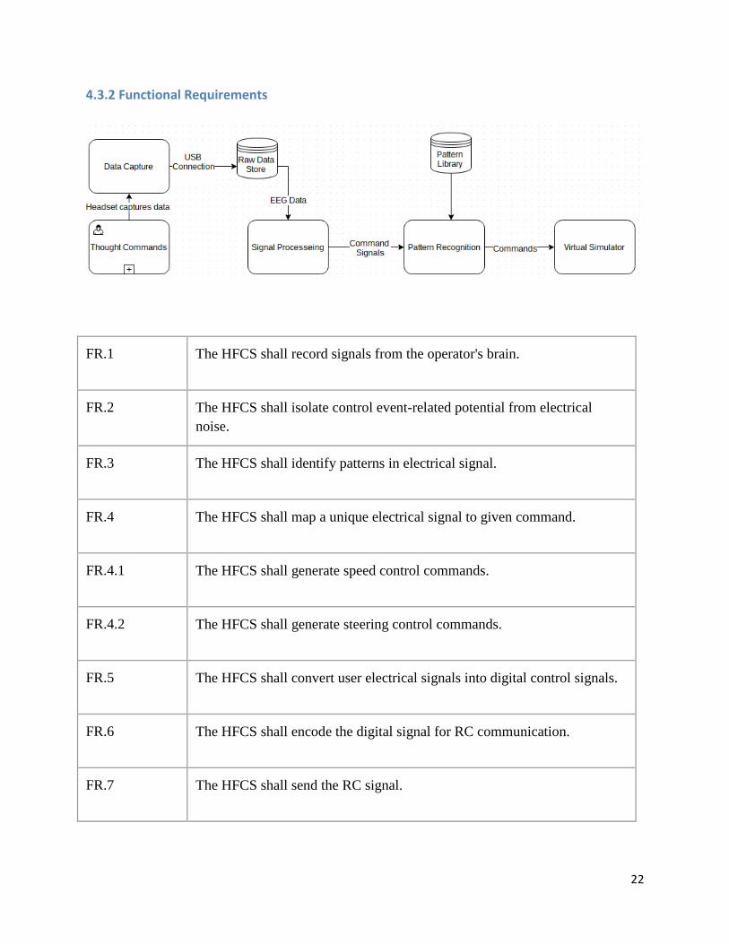
4.3.2 Functional Requirements
FR.1 The HFCS shall record signals from the operator's brain.
FR.2 The HFCS shall isolate control event-related potential from electrical
noise.
FR.3 The HFCS shall identify patterns in electrical signal.
FR.4 The HFCS shall map a unique electrical signal to given command.
FR.4.1 The HFCS shall generate speed control commands.
FR.4.2 The HFCS shall generate steering control commands.
FR.5 The HFCS shall convert user electrical signals into digital control signals.
FR.6 The HFCS shall encode the digital signal for RC communication.
FR.7 The HFCS shall send the RC signal.
23
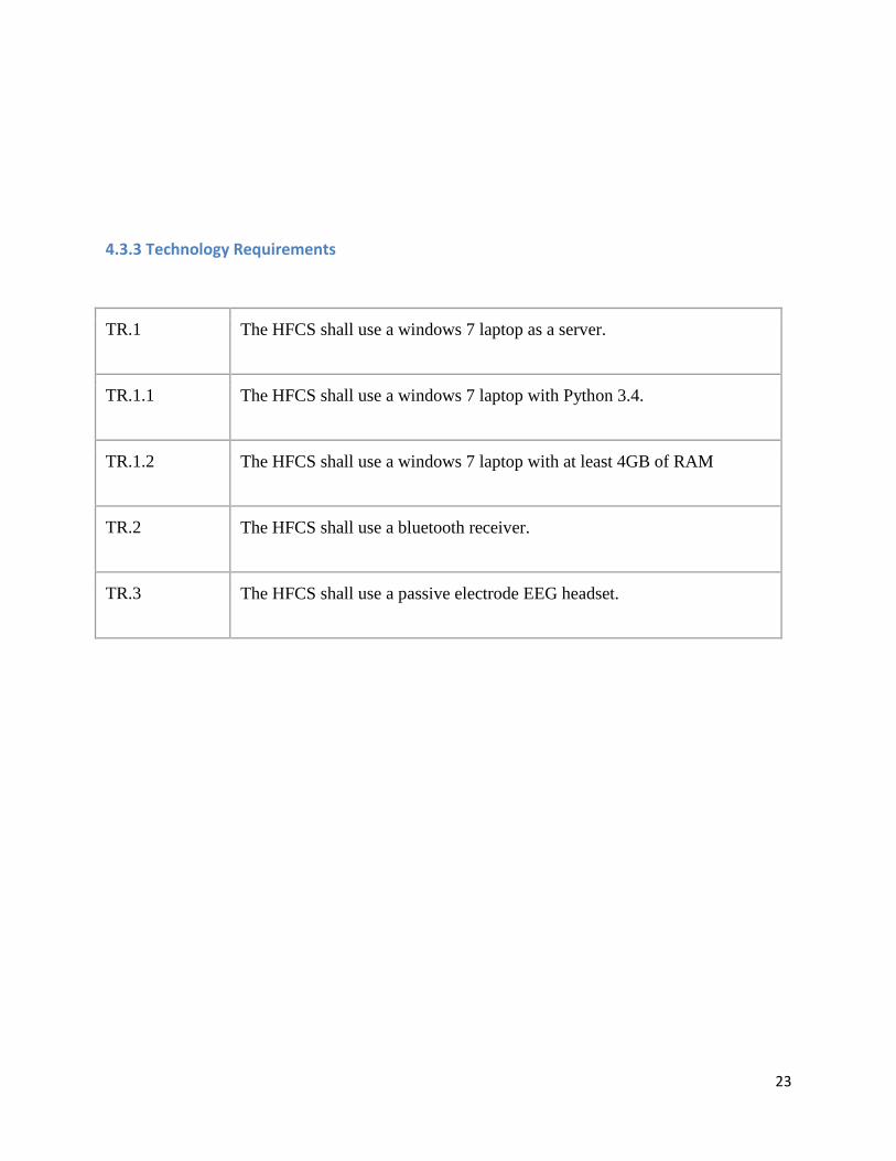
4.3.3 Technology Requirements
TR.1 The HFCS shall use a windows 7 laptop as a server.
TR.1.1 The HFCS shall use a windows 7 laptop with Python 3.4.
TR.1.2 The HFCS shall use a windows 7 laptop with at least 4GB of RAM
TR.2 The HFCS shall use a bluetooth receiver.
TR.3 The HFCS shall use a passive electrode EEG headset.

24
5.0 Project Plan
5.1 SOW
See Appendix 1 for complete SOW.
5.2 WBS
5.3 Schedule
MS
Proj
#
WBS
#
Task Name Start Finish Pred.
1 1 General Research Mon 8/31/15 Mon 9/7/15
2 2 Problem Definition
3 2.1 Preliminary Research Mon 9/7/15 Sun 11/1/15
4 2.2 Context Tue 9/8/15 Tue 9/29/15 1
5 2.3 Problem Statement Wed 9/30/15 Tue 10/6/15 4
6 2.4 Need Statement Wed 9/30/15 Tue 10/13/15 4

25
7 2.5 Stakeholder Analysis Wed 9/30/15 Tue 10/13/15 4
8 2.6 Gap Analysis Wed 9/30/15 Tue 10/13/15
9 2.7 Win-Win Wed 9/30/15 Tue 10/13/15
10 2.8 Systems Boundary Diagram Thu 10/1/15 Wed 10/7/15
11 3 CONOPS
12 3.1 Requirements Wed 10/7/15 Tue 10/20/15 5
13 3.2 Operational Scenario Wed 10/21/15 Tue 10/27/15 12
14 3.3 Analysis for areas of
improvement
Wed 10/21/15 Tue 10/27/15 12
15 3.4 Alternatives Wed 10/21/15 Tue 10/27/15 12
16 4 System Architecture Sat 10/24/15 Sun 10/25/15
17 4.1 Define Functional Architecture Wed 10/21/15 Tue 10/27/15 12
18 4.2 Define Allocated Architecture Wed 10/21/15 Tue 10/27/15 12
19 4.3 Define Interface Architecture Wed 10/21/15 Tue 10/27/15 12
20 4.4 Define Physical Architecture Wed 10/21/15 Tue 10/27/15 12
21 5 Model
22 5.1 Prototyping Wed 10/28/15 Tue 11/17/15 20
23 5.2 Develop test plan Wed 10/21/15 Tue 10/27/15 12
24 5.3 Perform test activities Wed 11/18/15 Tue 11/24/15 22
25 5.4 Model Accuracy Wed 11/25/15 Wed 11/25/15 24
26 6 Analysis
27 6.1 Perform Value analysis Thu 11/26/15 Wed 12/2/15 25
28 6.2 Perform Utility vs Cost analysis Thu 11/26/15 Wed 12/2/15 25
29 6.3 Provide recommendations Thu 11/26/15 Wed 12/2/15 25
30 7 Project Management
31 7.1 Project Budget & Tracking Mon 8/31/15 Tue 9/15/15

26
32 7.2 Project Schedule & WBS Mon 8/31/15 Tue 9/15/15
33 7.3 SOW Wed 9/16/15 Wed 9/16/15 32
34 7.4 Weekly tasks Mon 8/31/15 Sat 12/12/15
35 8 Documentation
36 8.1 Interim Briefings Wed 10/21/15 Mon 11/9/15
37 8.2 Final Presentation Mon 3/28/16 Tue 5/10/16
38 8.3 Final Report Mon 3/28/16 Tue 5/10/16
39 8.4 IEEE Paper Tue 3/1/16 Wed 3/30/16
40 8.5 Poster Mon 3/28/16 Tue 5/10/16
41 8.6 Proposal Presentation Wed 10/21/15 Wed 12/9/15
42 8.7 Proposal Final Report Wed 10/21/15 Wed 12/9/15
5.4 Critical Path Analysis
Current Critical Path Analysis, performed in MS Project, returns the follow tasks as critical path
tasks:
2.3 Problem Statement
3.1 Requirements
4.4 Physical Architecture
5.3 Perform Test Activities
8.2 Final Presentation
8.3 Final Report

27
5.5 Project Risk Mitigation
Risk # Foreseeable Risk Mitigation Strategies
1 Delivery of Equipment 1a. Order equipment asap
2 Data Collection - quality of
equipment, data quality 2a. Careful review of equipment reviews before
ordering
2b. Research data collection techniques
3 Access to raw data 3a. Contact equipment company
3b. Find contacts within Mason community
4 Data analysis timeline
driven by data collection/
equipment
4a. Develop test plan in line with system
architecture 4b. Closely monitor progress towards project
completion.
5.6 Planned Budget
● Labor cost - $40/ hr
● Hourly rate - $85.40
○ GMU Overhead rate 2.13
● Planned hours - 1,576
● Equipment cost - $400
● Planned Budget = $134,990.00

28
Works Cited
"Applying Human Factors and Usability Engineering to Optimize Medical Device Design."
Draft Guidance for Industry and Food and Drug Administration Staff. US Food and Drug
Administration, 22 June 2011. Web. 21 Oct. 2015.
Brigham, K.; Kumar, B.V.K.V., "Imagined Speech Classification with EEG Signals for Silent
Communication: A Preliminary Investigation into Synthetic Telepathy," in Bioinformatics and
Biomedical Engineering (iCBBE), 2010 4th International Conference on , vol., no., pp.1-4, 18-
20 June 2010
Carmicheal, Mary. "Neurmarketing: Is It Coming to a Lab near You?" PBS. PBS, n.d.
Web. 21 Oct. 2015.
"Emotiv EPOC / EPOC+:Scientific contextual EEG." Wearables for Your Brain. Emotiv, n.d.
Web. 21 Oct. 2015.
"Summary Health Statistics Fr US Adults." Vital and Health Statistics 10th ser. 260
(2012): n. pag. National Health Institute Survey. Center for Health Statistics, 2012. Web.
20 Oct. 2015.
Smart, John M. "What Brain Features Do We Need." Preserving the Self for Later
Emulation: What Brain Features Do We Need? Institute for Ethics and Emerging
Technology.
Sinha, Manish, DR. "EEG." NerveCarecom. Neurlogy, Epilepsy & Stroke Center, n.d. Web. 21
Oct. 2015.

29
Appendix I - SOW
STATEMENT OF WORK
Hands-Free Control System for Physical Manipulation Wednesday, September 30, 2015
1. INTRODUCTION
Hands-free control systems are widely regarded as the future of human-machine interactions.
These systems have the potential to reduce the workload on a human operator, allowing them to
perform more intensive tasks with a higher degree of accuracy. Innovative application of hands-
free control systems has the potential to revolutionize the way of life across industries, countries
and programs. A robust, accurate hands-free control system has the potential to give disabled
persons the ability to control a wheelchair, interact with a computer or cell phone and even
operate a vehicle.
Examples of hands-free control systems include voice recognition software and brain-computer
interfaces. Currently, these hands-free control systems lack the precision and ease of use found
in traditional control systems. These shortfallings can largely be attributed to the recent discovery
of these capabilities and the ever-growing capabilities of modern computing. The concept of
hands-free technology remains a front -running option in the search to revolutionize control
systems. While technology to ensure signal clarity and transmittal necessary to apply hands-free
control systems to time-sensitive applications is still being developed, progress towards a
deliverable system can be made by developing the interface between raw brain signal data and
control system.
2. OBJECTIVE
A key mission for the organization is the development of a system to record and identify signals
from a user’s brain with the objective of translating these signals to the triggers needed to move
an external device. To accomplish these tasks necessitates in-depth knowledge and expertise in
all areas of requirements elicitation, design, documentation, implementation, management to
ensure that requirements are met and deliverable products comply with the quality expectations
of the customer and industry needs.
The objective of this Statement of Work is to obtain a contract to provide support for on-going
development efforts and new efforts described within this Statement of Work (SOW). Expected
benefits of this R&D project include:
● Subset of brain signals mapped to the specific thought which generated the signal
● Documented process to identify and map new brain signals
● Increased value of a hands-free application
● Quality deliverables and products produced
● Improved benefits realization of hands-free control systems

30
3. SCOPE
The scope of this effort includes services necessary to provide a prototype hands-free control
system and documentation necessary to extend the prototype. Primarily, but not exclusively,
services provided will focus on 1) identifying brain signals (and the thought that created the
signal) from raw data and 2) mapping a brain signal to a physical control system. The project will
evaluate the complete current hands-free control system and evaluate areas to focus
improvement efforts.
Specifically, the scope of the project includes: ● Project Management
● Documentation
● Data Collection & Analysis Process
● Test Plan & Criteria
● Delivery of a Prototype
● Test Results
● Utility Analysis
● Plan for future expansion
4. REQUIREMENTS AND TASKS
4.1. REQUIREMENTS
Because of the complexity of the system, only the highest level, mission requirements will
be listed in this document. A complete requirement hierarchy may be found in Appendix I.
Mission Requirements:
M.1. The system shall enable users to manipulate a device at or exceeding a
performance ratio of at least X% when compared to a traditional control method.
M.2 The system shall be feasible in X% of settings.
M.3 The system shall yield results that either maintain or improve current control
methods.
4.2. TASKS
Several types of tasking will be completed in order to fulfill to perform the work described in
Section 3. This will include, but is not limited to, project management & budgeting, system
architecture, data cleaning and analysis, programming and prototype testing. Due to the
complexity of the system, specific tasking will not be listed in this document; a complete WBS
may be found in Appendix II.
5.0 DELIVERABLES & SCHEDULE The project team shall develop the system and documentation for use as a prototype with the
capability to be expanded and built upon.
The below table dictates deliverables and their due dates.

31
Deliverable Contents Delivery on or before
Brief One Context, Stakeholder Analysis, Problem Statement
9-21-2015
Brief Two Context, Stakeholder Analysis, Problem & Need Statement, Requirements, SOW, Budget, Risks
10-05-2015
Project Plan Project Plan due (1) Presentation, (2) Report: Context Analysis (prelim), Stakeholder Analysis (prelim), Problem Statement, Needs Statement, Proposed Solutions/Alternates, Simulation Design (prelim), WBS and Budget
10-21-2015
Brief Three Context/Stakeholder Analysis, Problem Statement, Need Statement, Mission/Functional/Design Reqs, Sim Reqs/Design, DoE, SOW/Budget/Project Risks
10-26-2015
Brief Four Project Briefing 4 (Context/Stakeholder Analysis, Problem Statement, Need Statement, Mission/Functional/Design Reqs, Sim Reqs/Design, DoE, SOW/Budget/Project Risks)
11-09-2015
Proposal Presentation
Final Presentation encompassing entire project 12-09-2015
Report Final Report encompassing entire project 12-09-2015
Draft Conference Paper
Draft IEEE paper 12-09-2015
Draft Poster Draft of presentation poster encompassing project 12-09-2015
6.0 PROJECT MANAGEMENT 6.1 EXPECTED LOE & RESPONSIBLE ENGINEER
Expected Level of Effort can be best understood through the hourly estimates displayed on the WBS, in
Appendix II. A RACI matrix will be generated to better display engineer responsibilities as the project
progresses.
Assignments and progress towards completion will be tracked via meeting minutes and action items
stored at the bottom of the meeting minutes. A weekly timecard and accomplishment summary will be
submitted to aid hourly tracking and the provide details as to the progress the project team has made
each week. Three interim briefings will be provided over the course of the performance period to ensure
customer satisfaction as the prototype is being produced.
6.3 ESTIMATED COST & BUDGET

32
The estimated budget for the project is $134,990. This figure is driven by the estimated hours required
(reference WBS), a $40 hourly rate and the GMU 2.13 adjustment rate for overhead plus equipment cost.
7.0 ACCEPTANCE CRITERIA
Acceptance criteria will be driven by a prototype test plan. As the project goal is to advance the technical
readiness level, customer satisfaction is expected to be directly linked to the results of the utility vs cost
analysis and to the recommendations provided by the project team.
As a result, the documentation provided by the project team will focus on identifying the current
shortcomings of the hands-free control system technology and plans to develop a robust hands-free
control system.

33
APPENDICES
APPENDIX I Requirement Hierarchy
Mission Requirements
M.1. The system shall demonstrate use EEG as a control method.
M.1.1. The system shall move an object in a 2-D plane.
M.1.2. The system shall be commanded by a human operator.
M.1.2.1 The system shall be controlled without out the use of the operator’s hands.
M.1.2. The system shall demonstrate device reaction time.
M.1.3. The system shall demonstrate capability to add a command.
M.2. The system shall be demonstrated on a selected case study.
M.2.1 The system shall provide framework for application to other devices.
M.3. The system shall be operable by a single human user.

34
APPENDIX II Project Plan
Task # Task Name Estimated
Hours
1 Problem Definition 82
1.1 Preliminary Research 30
1.2 Context 30
1.3 Problem Statement 1
1.4 Need Statement 0.5
1.5 Stakeholder Analysis 5
1.6 Gap Analysis 10
1.7 Win-Win 0.5
1.8 Systems Boundary Diagram 5
2 CONOPS 90
2.1 Requirements 20
2.2 Operational Scenario 10
2.3 Analysis for areas of improvement 10
2.4 Alternatives 50
3 System Architecture 40
3.1 Define Functional Architecture 10
3.2 Define Allocated Architecture 10
3.3 Define Interface Architecture 10
3.4 Define Physical Architecture 10
4 Model 470
4.1 Prototyping
4.1.1 Generate EEG Prototype (current) 100
4.1.2 Baseline prototype 20
4.1.3 Generate prototype of alternatives 100
4.2.1 Testing
4.2.2 Develop test plan 50
4.2.3 Perform test activities 100
4.3 Model Accuracy 100
5 Analysis 210
5.1 Perform Value analysis 20
5.2 Perform Utility vs Cost analysis 40

35
5.3 Provide recommendations 150
6 Project Management 135
6.1 Project Budget & Tracking 50
6.2 Project Schedule & WBS 50
6.3 SOW 5
6.4 Weekly tasks 30
7 Documentation 540
7.1 Interim Briefings 90
7.2 Final Presentation 100
7.3 Final Report 150
7.4 IEEE Paper 100
7.5 Poster 100

36
Appendix II - DoD TRL
http://www.acq.osd.mil/chieftechnologist/publications/docs/TRA2011.pdf

37