design of 3-dof parallel manipulators for micro-motion ... · design of 3-dof parallel manipulators...
TRANSCRIPT

Design of 3-DOF Parallel Manipulators for
Micro-Motion Applications
By
JIAN LI
A Thesis Submitted in Partial Fulfillment
Of the Requirements for the Degree of
Master of Applied Science
in
The Faculty of Engineering and Applied Science
Mechanical Engineering Program
University of Ontario Institute of Technology
August, 2009
© Jian Li, 2009
CERTIFICATE OF APPROVAL
Submitted by: Jian Li Student #: 100332892 First Name, Last Name In partial fulfillment of the requirements for the degree of: Master of Applied Science in Mechanical Engineering Degree Name in full (e.g. Master of Applied Science) Name of Program Date of Defense (if applicable): __________________________________
Thesis Title: Design of 3-DOF Parallel Manipulators for Micro-Motion Applications The undersigned certify that they recommend this thesis to the Office of Graduate Studies for acceptance:
____________________________ ______________________________ _______________ Chair of Examining Committee Signature Date (yyyy/mm/dd) ____________________________ ______________________________ _______________ External Examiner Signature Date (yyyy/mm/dd) ___________________________ ______________________________ _______________ Member of Examining Committee Signature Date (yyyy/mm/dd) ____________________________ ______________________________ _______________ Member of Examining Committee Signature Date (yyyy/mm/dd) As research supervisor for the above student, I certify that I have read the following defended thesis, have approved changes required by the final examiners, and recommend it to the Office of Graduate Studies for acceptance: _________________________ _________________________________ __________________ Name of Research Supervisor Signature of Research Supervisor Date (yyyy/mm/
ii
Abstract
This thesis presents two unique micro-motion parallel kinematic manipulators (PKM):
a three degrees of freedom (3-DOF) micro-motion manipulator and a 3-DOF micro-motion
manipulator with actuation redundancy. The 3-DOF micro-motion manipulator has three
linear-motion driving units, and the 3-DOF micro-motion manipulator with redundancy has
four of these units.
For both designs, the linear motion driving units are identical, and both machines
have a passive link in the center of the structure. The purpose of this passive link is to
restrain the movement of the manipulator and to improve the stiffness of the structure. As a
result, both structures support 3-DOF, including one translation on the Z-axis and two
rotations around the X and Y axes. The manipulator with redundancy is designed to prevent
singularity and to improve stiffness.
In this thesis, the inverse kinematic, Jacobian matrix and stiffness analyses have been
conducted, followed by the design optimization for structures. Finally, the FEA (Finite
Element Analysis) and dynamic analysis have also been performed.
There are many practical applications for micro-motion parallel manipulators. The
typical applications include micro-machine assembly, biological cell operation, and micro-
surgery .
iii
Acknowledgements
First, I would like to acknowledge Dr. Dan Zhang for giving me the opportunity to
study and work under his supervision. He has been an excellent advisor, as I have obtained
the required scientific and engineering knowledge, and I have discovered new ways to
perceive situations and to solve problems with his guidance. Dr. Zhang has been an
invaluable resource; he is my teacher, my mentor, and also my friend.
Also, I wish to thank all the fellows with whom I have studied. In particular, I would
like to give my special thanks to Qi Shi, who provided wonderful support, and whom without,
I could not be successful in completing this thesis. I also want to thank my family, especially
my wife, my parents, my sister and my friends, who supported and encouraged me
throughout my studies.
iv
Contents
Abstract………………………………………………………………………………………ii
Acknowledgement…………………………………………………………………………..iii
Contents………………………………………………………………………...…………….iv
List of Figures……………………………………………………………….……..………vii
List of Tables………………………………………………………………………………..xi
List of Acronyms……………………………………………………………………………xii
1. Introduction…………………………………………………………....………………1
1.1 Literature review………………………………………………………………1
1.1.1 Serial Robotic Machine Tool………………………………………….4
1.1.2 Parallel Robotic Machine Tool………………………………………..6
1.2 Parallel Robot Based Micro Motion Systems………………...……………….8
1.2.1 Introduction and Applications………………………….……….……..8
1.2.2 Existing Micro Motion Systems……………………………………10
1.3.3 Organization of the Thesis…………………………………...15
2. The Novel Three Degrees of Freedom Micro Motion System……………………16
2.1 Description of the New 3-DOF Micro Motion Manipulator...……...16
2.2 The Advantage of the New Micro Motion Manipulator…………….20
2.3 CAD Modeling Descriptions………………………………………………...21
2.4 Potential Applications………………………………………………………..22
3. Kinematic Modeling of 3-DOF Micro Motion Manipulator……………………...…25

v
3.1 Kinematics Modeling………………………………………………………...25
3.2 Inverse Kinematics…………………………………………………………...28
3.3 Forward Kinematics………………………………………………………….32
3.4 Jacobian Matrix………………………………………………………………36
3.5 Stiffness Modeling…………………………………………………………...44
3.6 Conclusion…………………………………………………………………...50
4. Kinematic Modeling of a 3-DOF Micro Motion Manipulator with Actuation
Redundancy………………………………………………………………………...52
4.1 CAD Modeling of the 3-DOF Micro Motion Manipulator with Actuation
Redundancy…….……………………….………….………………………..52
4.2 Inverse Kinematics…………………………………………………………...57
4.3 Jacobian Matrix……………………………………………………………...60
4.4 Stiffness Modeling…………………………………………………………...62
4.5 Conclusion…………………………………………………………………...68
5. Design Optimization…………………………………………………………………69
5.1 Introduction of Optimization Methods………………………………………69
5.2 Implementation of Optimization……………………………………………..71
5.2.1 Optimization of 3-DOF Micro Motion Parallel Manipulation………71
5.2.2 Optimization of 3-DOF Micro-Motion Parallel Manipulator with
Actuation Redundancy…………………………………………….…75
5.3 Conclusion…………………………………………………………………...78
6. Simulation and Comparison…………………………………………………………79
6.1 Finite Element Method Analysis…………………………………………...79
vi
6.2 Velocity and Acceleration Analysis………………………………………….84
6.2.1 Velocity and Acceleration Analysis of 3-DOF Micro-Motion Parallel
Manipulator…………………………………………………………..87
6.2.1 Velocity and Acceleration Analysis of 3-DOF Micro-Motion
Parallel Manipulator with Actuation Redundancy…………………..91
7. Conclusion and Future Work………………………………………………………...96
7.1 Conclusion…………………………………………………………………...96
7.2 Future Work………………………………………………………………….99
References………………………………………………………………………………….100
vii
List of Figures
1.1 Serial Robot and Conventional Machine Tool……………………………….…….….5
1.2 Exechon X700 Transparent (Courtesy of Exechon AB Sweden)…………..…………7
1.3 Desktop Micro CNC Machine KOSY3 A5 (Courtesy of MAX Computer Gmbh,
Germany)…………………………………………………………………………….9
1.4 H e x a p o d s R o b o t i n S p i n a l S u r g e r y ( C o u r t e s y o f M a z o r S u r g i c a l
Technologies)……………………..………………………………………………….11
1.5 ALIO HR2 Hexapod (Courtesy of ALIO Industries)………………………….….....12
1.6 New CAD Model…………………………………………………………………...13
1.7 The Dimensions of Newly Designed Micro-Motion Parallel Manipulator………..14
2.1 3-DOF Micro Motion Manipulator Model………………………………….17
2.2 3-DOF Micro Motion Manipulator with Actuation Redundancy………………..….18
2.3 Derivation CAD Model (Three legs)…………………………………………….…..19
2.4 Derivation CAD Model (Four legs) Redundant Structure…………………….……..20
2.5 CAD Model with Components Description………………………………………….21
2.6 The Application as a CNC Machine………………………………………………...24
3.1 Schematic Model of 3-DOF Micro Motion Parallel Manipulator Model…………....26
3.2 D-H Coordinate Frames for the Passive Constraining Leg………………………...37
3.3 Stiffness in X axis (a)………………………………………………………………...45
3.4 Stiffness in X axis (b)……………………………………………………………….46
3.5 Stiffness in X axis (c)………………………………………………………………..46

viii
3.6 Stiffness in Y axis (a)………………………………………………………………..47
3.7 Stiffness in Y axis (b)……………………………………………………………….47
3.8 Stiffness in Y axis (c)………………………………………………………………..48
3.9 Stiffness in Z axis (a)………………………………………………………………..48
3.10 Stiffness in Z axis (b)………………………………………………………………..49
3.11 Stiffness in Z axis (c)………………………………………………………………..49
4.1 3-DOF Micro Motion Parallel Manipulator with Actuation Redundancy…...54
4.2 Schematic Model of 3-DOF Micro Motion Parallel Manipulator with Actuation
Redundancy…………………………………………………………………………..56
4.3 Stiffness in X axis (a)………………………………………………………………...63
4.4 Stiffness in X axis (b)………………………………………………………………..64
4.5 Stiffness in X axis (c)………………………………………………………………...64
4.6 Stiffness in Y axis (a)………………………………………………………………...65
4.7 Stiffness in Y axis (b)………………………………………………………………..65
4.8 Stiffness in Y axis (c)………………………………………………………………...66
4.9 Stiffness in Z axis (a)………………………………………………………………...66
4.10 Stiffness in Z axis (b)………………………………………………………………...67
4.11 Stiffness in Z axis (c)………………………………………………………………...67
5.1 The Optimization Result of 3-DOF Micro Motion Parallel Manipulator with Genetic
Algorithm………………………………………………………………………….…73
5.2 The Optimization Result of 3-DOF Micro Motion Parallel Manipulator with
Actuation Redundancy........................................................................................…....76
ix
6.1 Moving Plate FEM Simulation of 3-DOF Micro Motion Parallel Manipulator with
Passive Leg…………………………………………………………………………81
6.2 Moving Plate FEM Simulation of 3-DOF Micro Motion Parallel Manipulator with
Actuation Redundancy………………………………………………………….…...81
6.3 Moving Link FEM Simulation of 3-DOF Micro Motion Parallel Manipulator with
Actuation Redundancy ……………...……………………………………………….82
6.4 Tri-Angle Support FEM Simulation of 3-DOF Micro Motion Parallel
Manipulator ……………….........................................................................................82
6.5 Driving Block FEM Simulation of 3-DOF Micro Motion Parallel Manipulator with
Actuation Redundancy …………………………………………………………......83
6.6 Tri-Angle Support FEM Simulation of 3-DOF Micro Motion Parallel Manipulator
with Actuation Redundancy ........................................................................................83
6.7 Adams/View model of the 3-DOF Micro Motion Parallel Manipulator with Passive
Leg………………………………………………………………………………….87
6.8 Displacements, Velocity, and Acceleration of Link 1………………………………88
6.9 Displacements, Velocity, and Acceleration of Link 2………………………………89
6.10 Displacements, Velocity, and Acceleration of Link 3………………………………89
6.11 Displacements, Velocity, and Acceleration of Moving Platform…………………....90
6.12 Adams/View model of the 3-DOF Micro Motion Parallel Manipulator with Actuation
Redundancy…………………………………………………………………….……91
6.13 Displacements, Velocity, and Acceleration of Link 1…………………………...….92
6.14 Displacements, Velocity, and Acceleration of Link 2………………………………93
6.15 Displacements, Velocity, and Acceleration of Link 3………………………………93
x
6.16 Displacements, Velocity, and Acceleration of Link 4………………………………94
6.17 Displacements, Velocity, and Acceleration of Moving Platform...………………94
xi
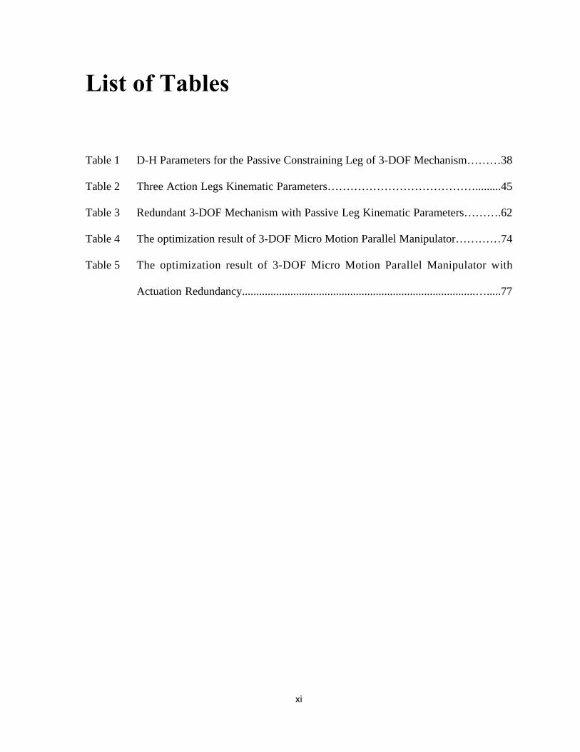
List of Tables
Table 1 D-H Parameters for the Passive Constraining Leg of 3-DOF Mechanism………38
Table 2 Three Action Legs Kinematic Parameters………………………………….........45
Table 3 Redundant 3-DOF Mechanism with Passive Leg Kinematic Parameters……….62
Table 4 The optimization result of 3-DOF Micro Motion Parallel Manipulator…………74
Table 5 The optimization result of 3-DOF Micro Motion Parallel Manipulator with
Actuation Redundancy..................................................................................….....77
xii
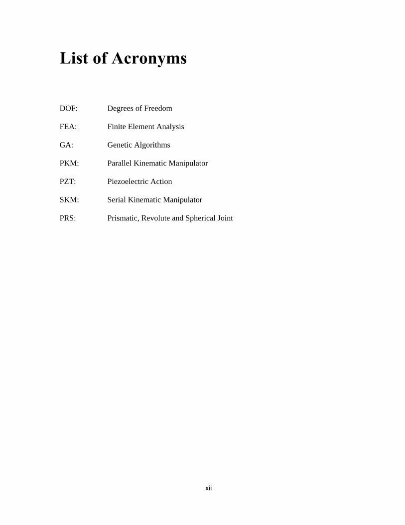
List of Acronyms
DOF: Degrees of Freedom
FEA: Finite Element Analysis
GA: Genetic Algorithms
PKM: Parallel Kinematic Manipulator
PZT: Piezoelectric Action
SKM: Serial Kinematic Manipulator
PRS: Prismatic, Revolute and Spherical Joint

xiii
1
Chapter 1
Introduction
1.1 Literature review
There is an abundance of research on the Parallel Kinematic Manipulator (PKM),
most of which examines either the Micro Machine or Micro Motion Structures [1, 2].
Recently, there has been an increasing trend in the research of micro machines, as
industries want to make current machines smaller, more energy-efficient and precise. For
instance, Liu [3] has developed an intelligent micromanipulator based on 3-PRS in parallel
mechanisms. Moreover, Harashima [4] has introduced a new type of integrated micro-
motion systems Bang [5] designed a micro parts assembly system with a micro gripper, and
Zubir [6] expanded on this research to present a newly developed high-precision micro
gripper. Finally, Gilsinn [7] focused on a macro-micro motion system for a scanning,
tunneling microscope.

2
There are many benefits of micro machines, especially in comparison to regular
machines. For instance, they are relatively small, they have a higher precision and they
consume much less energy than a regular machine. These characteristics make micro
machines popular in the fields of information and telecommunications, medicine,
biotechnology, and the automotive industry. Specifically, micro machines are regarded as a
vital component for strengthening international competition in major areas of the
manufacturing industry [8]. Applications related to these machines are expected to be in high
demand by many companies in the near future. [9].
The application of the micro machine tool, especially with its high degrees of
precision and speed, provides significant benefits for the manufacturer. Specifically, it can
help to increase the accuracy and precision in production, and the recent trends towards high-
speed micro machining have been a very popular field of research in developing new types of
parallel kinematics machines [10].
Three Degrees of Freedom (DOF) is the basic requirement for the parallel kinematics
machines. Since most machine operations only require a maximum of 5 axes, new
configurations with less than six parallel axes would be appropriate for these operations [11].
A substantial amount of research has been conducted on the 3-DOF parallel kinematics
manipulator. For example, Clavel [12] and Sternheim [13] reported a 3-DOF high-speed

3
robot known as the Delta Robot, while Lee and Shah [14] analyzed a 3-DOF parallel
manipulator. Some 3-DOF parallel manipulator architectures provide a pure relative rotation
of the moving platform and are used as point devices, manipulator wrists and orienting
devices [15, 16]. Tsai [17, 18] introduced a novel 3-DOF translation moving platform, which
is comprised of only revolute joints and performs pure translational motion. To improve the
stiffness of the 3-DOF PKM, Zhang [19, 20] proposed a passive link structure, which
increases the stiffness of the system. These research discoveries provide the foundations for
the 3-DOF PKM.
The 3-DOF Micro-Motion Parallel Manipulator can be applied to precision
manufacturing and assembly for small parts ranging in size from millimeters to micrometers.
Micro Machine Tools are in demand worldwide, and their popularity will also turn Micro
Motion Mechanisms into machines that can perform small motions and have very high
accuracy. In the subsequent sections, serial and parallel kinematic manipulators will be
introduced, then micro motion structures will be discussed, and finally, the new design of
micro motion structures will be described.
4
1.1.1 Serial Robotic Machine Tool
A serial robot is a serial mechanism with an open kinematic chain that is connected at
its base and its end effectors [21]. The first robotics patents were applied for by an American
inventor, George Charles Devol Jr., in 1954, and subsequently, they were granted in 1961.
However, robotics was not widely used in the industry until the early 1970’s, when robots
were utilized to replace human workers in monotonous and hazardous work environments by
companies such as General Electric and General Motors. Today, serial mechanisms are
extensively used in a wide variety of industrial areas. Some typical robotic applications
include welding, painting, assembly, pick and place, packaging, product inspecting, and
testing. There are many advantages to using robots, including a very large working area in
comparison to the size of the mechanism itself, and the relative ease of analyzing their
structure and range of motion.
Most conventional machine tools are designed based on the serial structure. However,
the existence of an open kinematic chain creates a number of disadvantages. First, it is
difficult to achieve a high degree of accuracy, since the system accumulates the individual
errors of sequentially linked components. Secondly, the cost of energy is expensive, since
heavy actuators, which drive the moving components directly or through a transmission
5
device, need to be installed on each component. Finally, their machining speed is limited,
since the system stiffness or rigidity is relatively low, causing the occurrence of vibration and
instability, thus resulting in lower efficiency and accuracy. Therefore, open kinematic chains
diminish the acceleration and speed, decrease the dynamic performance, and limit the system
stiffness at the end effector. As well, the load, forces, and weight of the upper axis must be
supported by the lower axis, which results in the poor dynamic behaviors of the lower axis
[22]. Overall, the limited performance of serial mechanisms demonstrates that they are
unsuitable for use as a precision micro motion manipulator.
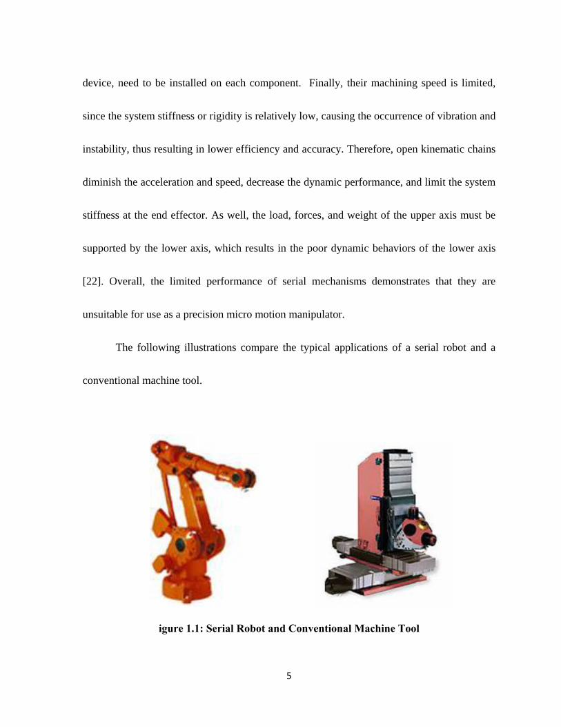
The following illustrations compare the typical applications of a serial robot and a
conventional machine tool.
igure 1.1: Serial Robot and Conventional Machine Tool
6
1.1.2 Parallel Robotic Machine Tool
A parallel kinematic manipulator (PKM) is a closed-loop mechanism, where a
moving platform is connected to the base by at least two serial kinematic chains, or legs [21].
The PKM has enormous potential for overcoming the disadvantages of serial robots. First,
this device is more accurate, since its moving components are more strongly related and the
link errors are not accumulated. Furthermore, it is much more rigid than a serial robot, as the
same end-effectors are simultaneously supported by at least two kinematic chains. Lastly, it
has a much lighter moving mass, as all of the actuators are mounted on the base, allowing it
to function at a higher speed and with greater precision.
The first conventional Stewart Platform (SP) kinematic manipulator was designed by
Gough [19]; it has six extensible legs and hence a very rigid kinematic structure. This system
consists of six linear actuators independently driven by six stepper motors. It can perform
translational movements and be implemented in precision engineering applications. In
comparison to the serial kinematic manipulator (SKM), the parallel kinematic manipulator
has the desirable characteristics of greater payload and rigidity, more precision, and higher
speed and acceleration. On the other hand, the disadvantages of the PKM include a limited
working envelope as well as more complex direct kinematics and control algorithms.

7
The parallel robot has the following advantages in comparison with the serial
manipulator:
High accuracy due to non-cumulative joint errors
High force/ torque capacity since the load is evenly distributed
Structural rigidity and stiffness
Therefore, parallel robots are suitable for applications in which high speed, high
positioning accuracy, and a rapid dynamic response are required.
Figure 1.2: Exechon X700 Transparent (Courtesy of Exechon AB of Sweden )
This design, which consists of two active moving pods and one passive pod, is
patented by Exchon AB of Sweden, and it has been used for CNC machine tool heads.

8
1.2 Parallel Robot Based Micro Motion Systems
1.2.1 Introduction and Applications
Precise micro-motion manipulation has become increasingly important in many
applications, such as small parts precision machining, chip assembly in the semiconductor
industry, cell manipulation in biotechnology, and automatic surgery. The micro-motion
system has been strongly recommended by researchers around the world, as it its materials
are less expensive and it is more energy efficient, and thus, this system represents the current
development direction in engineering.
At the same time, the advanced fabrication technique enables the miniaturization of
existing parallel robotic systems, whose motion ranges can vary from a few millimeters to
micrometers. The advantages of the micro-motion parallel kinematic manipulator can be
summarized in the following points [23, 24]:
Lower Inertia
Improved Dynamic Behavior
High Speed and Acceleration
Smaller Package Size
Greater Stiffness

9
Increased Repeatability and Reliability
The following illustration shows an example of the parallel kinematics manipulator
used in precision machining. This device is conventionally designed for specific functions,
such as the fabrication of watch parts and engraving.
Figure 1.3: Desktop Micro CNC Machine KOSY3 A5 (Courtesy of MAX computer
GmbH, Germany)
10
1.2.2 Existing Micro Motion Systems
As discussed in Section 1.2.1, there are many micro-motion structures that have been
designed and analyzed by researchers. Based on their defining characteristics, these machines
can be divided into two main types. The first type of micro-motion structure is a miniaturized
device that is driven by tiny actuators. Overall, the mechanism is usually less than one cubic
foot, and its motion range can vary from several micrometers to several centimeters.
The second type of micro motion system is a nano-positional micro motion
manipulator, also known as the piezoelectric (PZT). Generally, the actuation element of this
motion system is integrated with the compliant micro-motion system, and it can achieve high
degrees of stiffness and accuracy. However, according to their actuators, the motion ranges
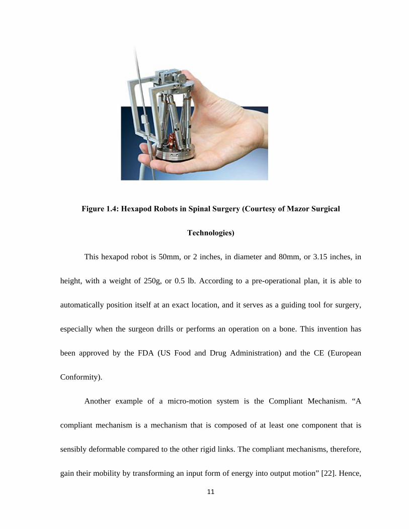
of this system are within 0 to 1000 µm [8]. Figure 1.4 demonstrates a conventional micro
PKM, which is successfully used in medical surgery.
11
Figure 1.4: Hexapod Robots in Spinal Surgery (Courtesy of Mazor Surgical
Technologies)
This hexapod robot is 50mm, or 2 inches, in diameter and 80mm, or 3.15 inches, in
height, with a weight of 250g, or 0.5 lb. According to a pre-operational plan, it is able to
automatically position itself at an exact location, and it serves as a guiding tool for surgery,
especially when the surgeon drills or performs an operation on a bone. This invention has
been approved by the FDA (US Food and Drug Administration) and the CE (European
Conformity).
Another example of a micro-motion system is the Compliant Mechanism. “A
compliant mechanism is a mechanism that is composed of at least one component that is
sensibly deformable compared to the other rigid links. The compliant mechanisms, therefore,
gain their mobility by transforming an input form of energy into output motion” [22]. Hence,
12
they are flexible mechanisms that transfer an input force or a displacement to another point
through the elastic body deformation of their flexible joints. Piezoelectric actuators (PZT) are
used in compliant machine structures for linear motion. They can develop a linear motion on
driving element and flexure pivots, which can receive a resolution range of 10 pm (1
10 to 100 um [8]. There are many companies that are making the micro-motion
systems, such as ALIO Industries and PI (Physik Instrumente).
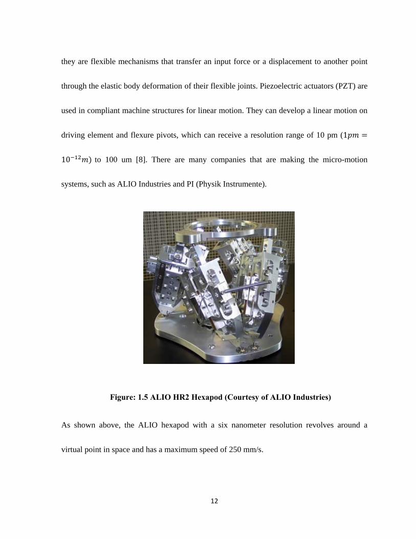
Figure: 1.5 ALIO HR2 Hexapod (Courtesy of ALIO Industries)
As shown above, the ALIO hexapod with a six nanometer resolution revolves around a
virtual point in space and has a maximum speed of 250 mm/s.
13
Some applications have special requirements, such as limited space for installation
and workspace requirements that are much larger than applications with a nano-scale
structure. For instance, nano-lithography does not have the capability of developing a large
work area. The newly developed designs intend to meet these two objectives, as this micro-
motion manipulator has been used successfully in areas such as jewelry engraving and micro-
precision machining for electronic circuits.
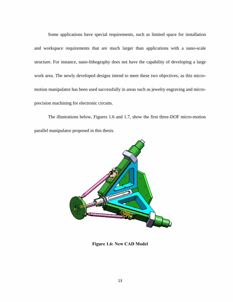
The illustrations below, Figures 1.6 and 1.7, show the first three-DOF micro-motion
parallel manipulator proposed in this thesis.
Figure 1.6: New CAD Model
14
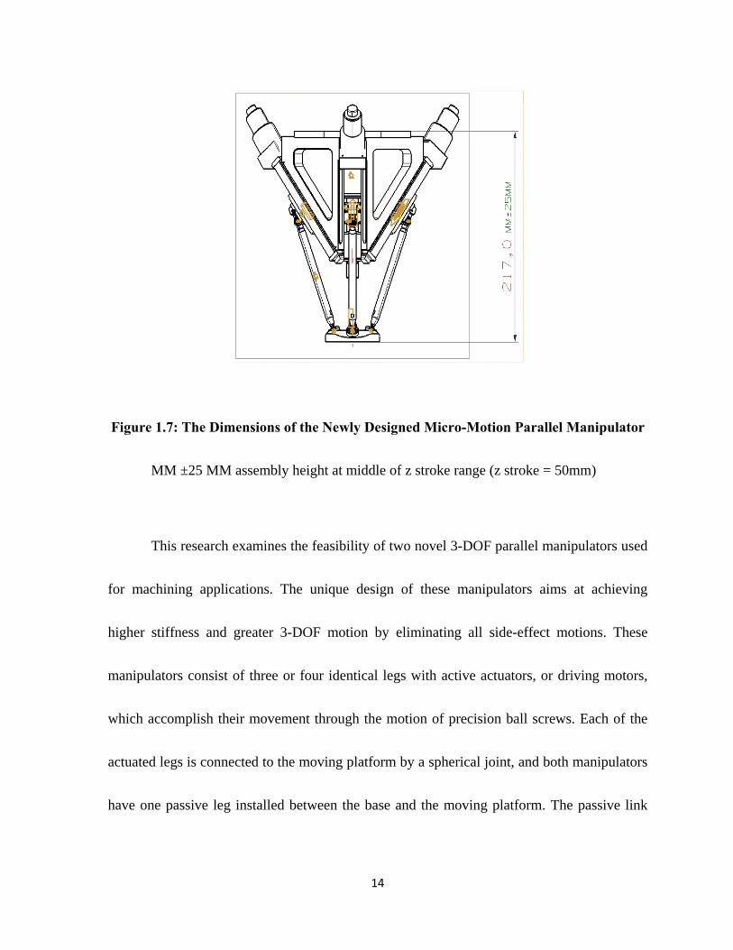
Figure 1.7: The Dimensions of the Newly Designed Micro-Motion Parallel Manipulator
MM ±25 MM assembly height at middle of z stroke range (z stroke = 50mm)
This research examines the feasibility of two novel 3-DOF parallel manipulators used
for machining applications. The unique design of these manipulators aims at achieving
higher stiffness and greater 3-DOF motion by eliminating all side-effect motions. These
manipulators consist of three or four identical legs with active actuators, or driving motors,
which accomplish their movement through the motion of precision ball screws. Each of the
actuated legs is connected to the moving platform by a spherical joint, and both manipulators
have one passive leg installed between the base and the moving platform. The passive link

15
can only have linear motion on the middle platform, while the other end is connected to the
moving platform by a universal joint, eliminating the rotation of the z-axis.
1.2.3 The Organization of the Thesis
Chapter 2 presents the concept design for the novel 3-DOF Micro-Motion Parallel
Manipulators. Specifically, several concepts detailing kinematic structure development are
addressed. Subsequently, Chapter 3 focuses on the kinematic analysis of the 3-DOF Micro-
Motion Parallel Manipulator with a passive leg, and Chapter 4 discusses the kinematic
analysis of the 3-DOF Actuation Redundant Micro-Motion Parallel Manipulator. Next,
Chapter 5 describes the optimization result of these two 3-DOF Micro-Motion Parallel
Manipulators. Chapter 6 presents the simulations, comparisons and the results of Finite
Element Analysis, as well as the result of Velocity and Acceleration Analysis. Finally,
Chapter 7 highlights the most important conclusions and observations of the study and
suggests ideas for future work.
16
Chapter 2
The Novel Three Degrees of Freedom
Micro Motion System
2.1 Description of the New Micro-Motion 3-DOF
Parallel Manipulators
Two types of micro-motion 3-DOF parallel kinematic manipulators are proposed in
this thesis: one kind contains three active links, and the other has four active links, which is
known as a redundant parallel manipulator. Both manipulators have a passive link that is
connected by a moving platform and a fixed base. Their active links are manipulated by a
high-precision ball screw that controls linear motion units and provides high speed as well as
a rapid response for the moving platform. Accordingly, Figures 2.1 and 2.2 represent two 3-
DOF novel parallel manipulator CAD models.
The first 3-DOF parallel kinematic manipulator, known as 3-DOF PKM, is shown in
Figure 2.1. This manipulator consists of four kinematic chains, including three actuated
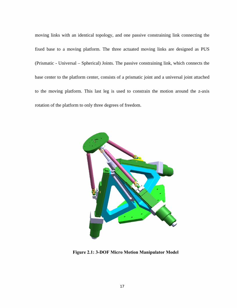
17
moving links with an identical topology, and one passive constraining link connecting the
fixed base to a moving platform. The three actuated moving links are designed as PUS
(Prismatic - Universal – Spherical) Joints. The passive constraining link, which connects the
base center to the platform center, consists of a prismatic joint and a universal joint attached
to the moving platform. This last leg is used to constrain the motion around the z-axis
rotation of the platform to only three degrees of freedom.
Figure 2.1: 3-DOF Micro Motion Manipulator Model
18
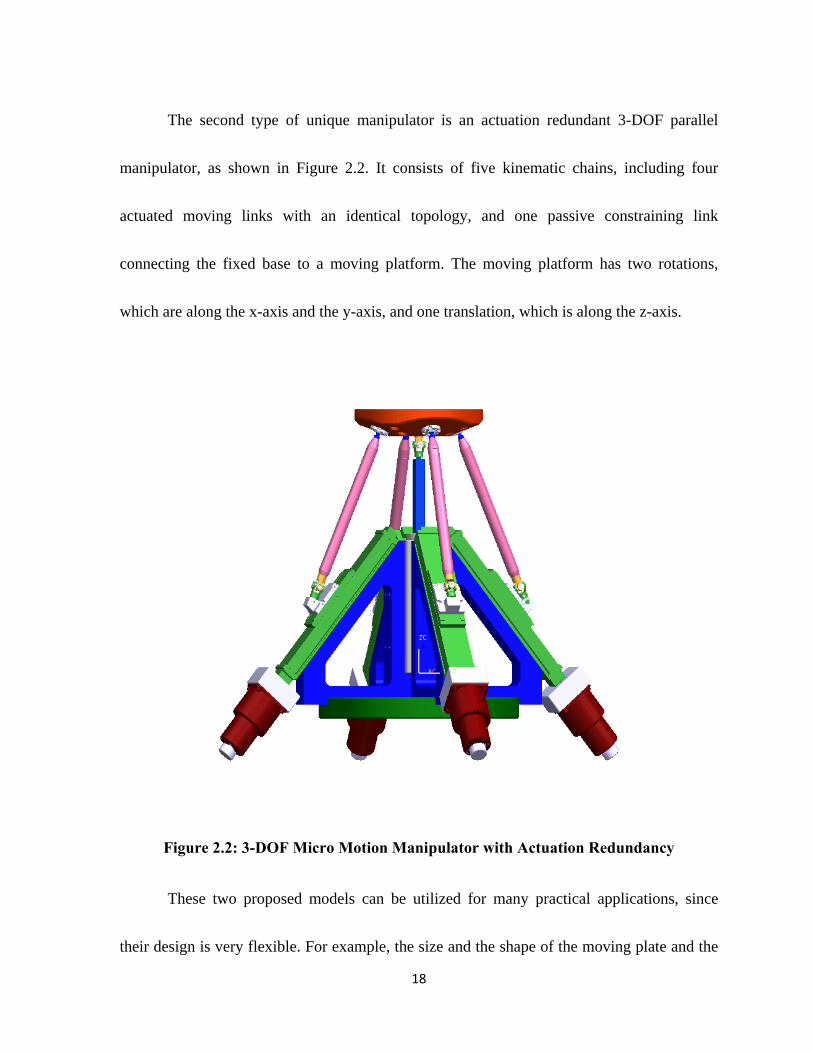
The second type of unique manipulator is an actuation redundant 3-DOF parallel
manipulator, as shown in Figure 2.2. It consists of five kinematic chains, including four
actuated moving links with an identical topology, and one passive constraining link
connecting the fixed base to a moving platform. The moving platform has two rotations,
which are along the x-axis and the y-axis, and one translation, which is along the z-axis.
Figure 2.2: 3-DOF Micro Motion Manipulator with Actuation Redundancy
These two proposed models can be utilized for many practical applications, since
their design is very flexible. For example, the size and the shape of the moving plate and the

19
base may have to be changed depending on the actual use, and the active driving motors or
actors can also be modified for the installation. The following figures depict two examples of
potential modifications.
Figure 2.3: Derivation of CAD Model (Three legs)
20
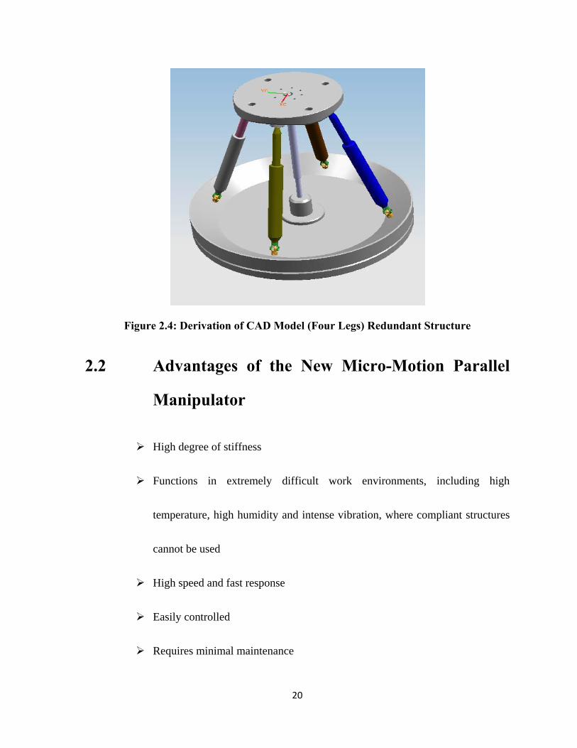
Figure 2.4: Derivation of CAD Model (Four Legs) Redundant Structure
2.2 Advantages of the New Micro-Motion Parallel
Manipulator
High degree of stiffness
Functions in extremely difficult work environments, including high
temperature, high humidity and intense vibration, where compliant structures
cannot be used
High speed and fast response
Easily controlled
Requires minimal maintenance
21
2.3 CAD Modeling Descriptions
As previously discussed, this thesis presents two types of models: the 3-DOF Micro-
Motion Parallel Manipulator, which has three identical action links, or legs, and the 3-DOF
redundant Micro-Motion Parallel Manipulator, which has four identical action links, or legs.
Also, both models contain one constraining link, or passive leg. The diagram below
demonstrates the first model, the 3-DOF Micro-Motion Parallel Manipulator. The
components that have the same name in the 3-DOF Micro-Motion Redundant model have the
same function as those in the 3-DOF Micro-Motion Parallel Manipulator.
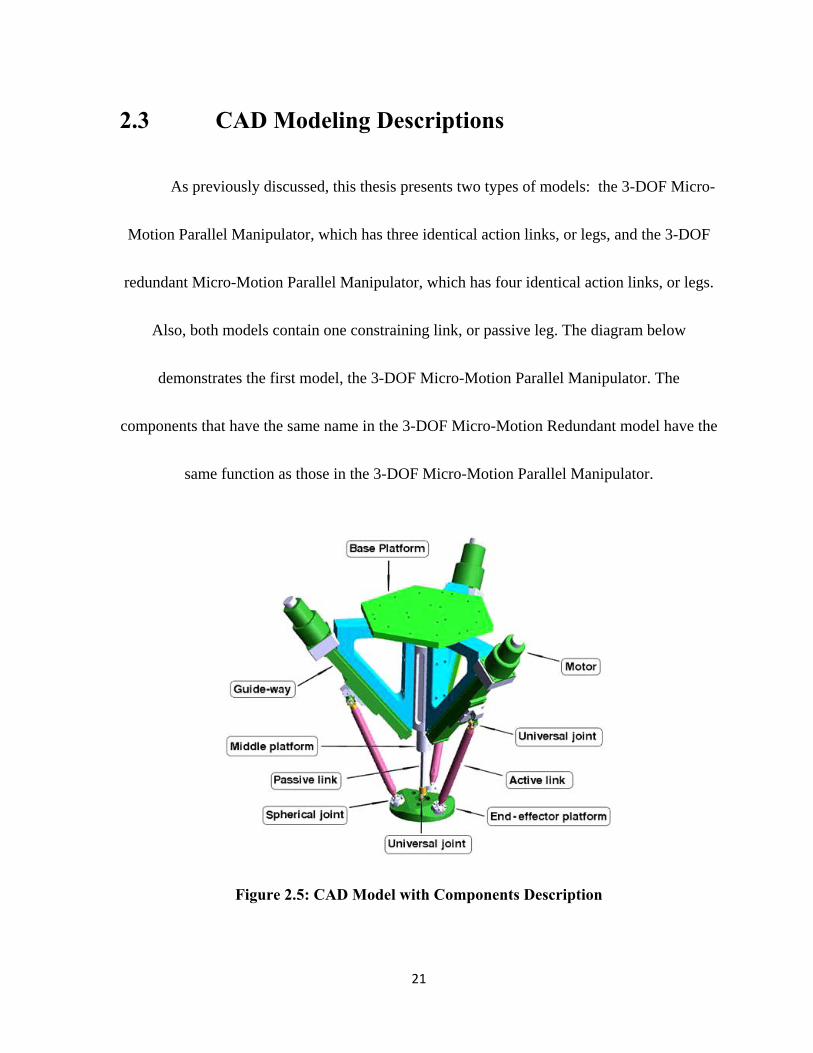
Figure 2.5: CAD Model with Components Description

22
In Figure 2.5, the micro-motion manipulator contains a base platform, an end-
effector, or moving, platform, and three identical actuated links that are controlled by the
motor through ball screws and the driving block. The actuated link is connected at one end
with a driving block, which slides on a guide-way. At one end of the link is a universal joint,
and at the other end of the link is a spherical joint, which is connected to the end-effector
platform. Additionally, three triangular blocks are arranged in 120-degree intervals around
the axis of the base platform. Depending on the application, the end-effector may be attached
to the end-effector platform, which is located at the bottom of the link mechanism.
2.4 Potential Applications
The newly-developed micro-motion manipulators have accomplished increasingly
demanding tasks in fields where high speed and high precision are required. They can be
modified for utilization as machine tool heads, and the tool heads can be attached to existing
systems, such as CNC machines, robots and CMM, to expand their motion range and their
dexterity [11, 26].
Hence, based on the design of these structures, this 3-DOF micro-motion manipulator has
been constructed with a 50 mm stroke along the z-axis and a 50° rotation on the x-axis and

23
the y-axis. They also have a 125mm moving platform diameter and a 250mm base platform
diameter; however, these specifications can be modified according to the individual
requirements.
Some potential applications include:
Watch industry
Assembly of micro-motors
Assembly of micro-sensors
Assembly of micro-technological devices
Packaged system
Micro-optical benches
Biological cell manipulation
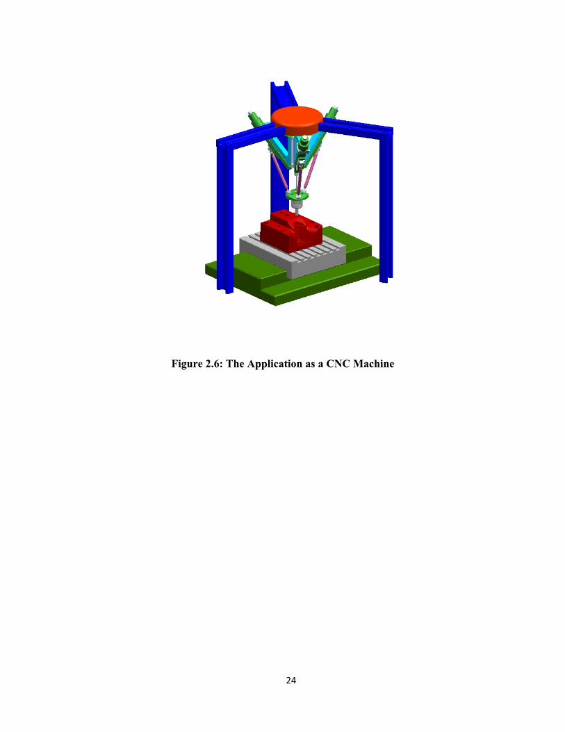
The following figure shows the manipulator being utilized as a CNC Machine in high
precision machining,
24
Figure 2.6: The Application as a CNC Machine

25
Chapter 3
Kinematic Modeling of the 3-DOF
Micro Motion Manipulator
3.1 Kinematics Modeling
Unlike most existing 3-DOF parallel kinematic manipulator designs, the new design
has improved the system’s stiffness by using a passive leg which was connected the moving
plate with a universal joint in the center of the moving platform [19, 20]. This design also
eliminated the coupled motions at the reference point to simplify the kinematic model and the
control.
As shown in Figure 3.1, this parallel manipulator includes a universal joint in the
passive link. It is located on the moving platform rather than the base platform so that the
motions along X and Y translations and Z rotation are eliminated.
The reference point is on the middle of the moving platform, which has uncoupled
motion with X and Y rotations and Z translation. The proposed manipulator has three

26
platforms: base platform , middle platform , and moving platform .
The base platform is fixed on the ground. The middle platform is used to support guide-
way of actuated links .The moving platform is used to mount a tool. Actuated
links are connected to the moving platform by a spherical joint (ball joint) at , and to
a slider connected to the active ball screw by a universal joint at . The passive link is
installed between the middle platform and the moving platform. The passive link with a
prismatic joint is fixed on the middle platform at one end, and connected to the end-effector
platform by a universal joint at the other end.
Figure 3.1 Schematic Model of 3 –DOF Micro Motion Parallel Manipulator Model

27
The following parameters define the details of the structure:
the angle ( i=1,2,3) between and ,
the angle ( i = 1,2,3) between and ,
the distance from on the base platform is ,
the distance from at the end-effector platform is ,
the angle of a guide-way γ,
the length of an active link , and
the offset of the spherical joints on the platform .
To describe the structure of the 3-DOF manipulator, two coordinate systems,
and , are established, which are attached to the end- effector
and base platform, respectively. For the origin of the end-effector, its translational
motions along and , and rotational motion along , are eliminated because of the usage
of the passive leg, i.e.,
0
0
x yp p
z
(3-1)
Therefore, the motions of can be denoted by , , , where and are the
rotational motions along and , and is the translational motion along . The position

28
of the end-effector with respect to the coordinate system can be represented
as following:
0 0
0
0 0 0 1
c sy y
s s c s cx y x x y
c s s c c zx y x x y p
R Pp pbTp 0 1 (3-2)
Where
C, S are denoted the cosine and sine functions, respectively,
is the pose of the end-effector with respect to the coordinate
system
RP is the 3×3 orientation matrix of the end-effector,
PP is the location of .
3.2 Inverse Kinematics
The inverse kinematics is formulated by finding the joint motions when the pose of
the end-effectors is known. The joint motions are denoted by and the pose of the end-
effector is determined by the motions of , , . To solve the inverse
kinematic problem, one can apply the condition that the length of a support bar is constant.

29
The location of the connection between the end-effector platform and an active link is:
0
0
0
p i y y
p i x y p i x x y
p i x y p i x p x y
r c c z s
r c s s r s c z s c
r c c s r s s z z c c
i i
b p bp p p pR p pp (3-3)
Where
Tb b bp p pi i i
x y z
bpi
p and 0
Tp pi ir c r s z
ppi
p
In Eq. (3-3), is the offset of the spherical joint with respect to coordinator system
and differentiate the Eq. (3-3) and get the result as follows:
3 6
x
y
zxp
yp
z p
bδx pibδy Jp iibδz pi
(3-4)
Where
0 0 0 0 00
0 0 0 00 0
0 0 0 10 0 3 6
r c s z cp y yi
r c s z c c r s s r c c z s sp y y x p x p y y xi i i
r c s z c s r s c r c c z s cp y y x p x p y y xi i i
Ji

30
Since the active links have a fixed length, then it can be shown that
O P O B B D D P 1,2,3b b ii i i i i i (3-5)
Eq.(3-5) can be yielded
2 2 2 21 2 3i i i i
k k k l (3-6)
Where
1
2
3
bp i ii bi
bp i ii bi
bp ii i
k x r u c c
k y r u c s
k z u s
(3-7)
Here, represents the angle of the guide-way, and assuming there is only linear
motion in the linear actuator of each active link, and the active link is a two-force component,
only axial deformation occurs.
Then Eq. (3-6) can be differentiated as following:
31
1 2 3
4 4 4
1 2 3
1, 2,3
i i i
i i i
i i i
i i i
bk k k pik k k b ipik k k
bl l l pi
x
y
z
δuiδli
(3-8)
Where
4 1 2 3k k c c k c s k si ii i i i
Substituting Eq. (3-4) into Eq. (3-8)
1
2
3
x x
y yu
z zu x xp pu
y yp p
z zp p
t,1 1×6
t t,23×6 1×6
t,3 1×6
J
J J
J
The twist of the platform can be defined as
T TT T x y zzx y p p p
t ω p (3-9)
Here, we have
1 2 3T
l l l Jtρ (3-10)
1 61
2 3 6 1 6
31 6
x x
y yl
z zl x xp pl
y yp p
z zp p
p,1
p p,2
p,3
J
J J
J
(3-11)

32
Where
1 2 3k k ki i i
l l li i i
J Jp i (3-12)
3.3 Forward Kinematics
The direct kinematics problem will solve the pose of the end-effectors when the
joint motion , , , is known. The solution of direct kinematic problem can also be
derived from Eq. (3-3). Currently the motions of the end effectors , , are unknown
and the joint motion , , , is given. To solve the direct kinematic problem,
and could be represented by
Therefore, Eq. (3-13) can be deduced from Eqs. (3-6) and (3-7)
2 0 1,2,3z A s B z C c D s E ip y p y yi i i i i (3-13)
As shown the coefficients A ~ E are the following functions of ,
33
2 2 2 2
2
2
2
2
2
p b
p pb
A r c cp xi i
B r s s u sp xi i i
C r u c r c cpi i i ib
D r c u s c r u c s sx xi i i i i
E r r u l r s u s s r u c s c r u cx xi i i i i i i ib b
(3-14)
From Eq. (3-13)
2p p
yp
Fz Gz HC
Kz L
(3-15)
py
p
Iz JS
Kz L
(3-16)
Where the coefficients F ~ L are functions of , expressed by
12 13 13 12
12 13 12 13 13 12 13 12
12 13 13 12
12 13 13 12
12 13 13 12
12 13 13 12
12 13 13 12
F B A B A
G E A B D E A B D
H E D E D
I C B C B
J C E C E
K C A C A
L C D C D
(3-17)
And
34
, ,
,
A A A B B B C C Cij i j ij i j ij i j
D D D E E Eij i j ij i j
(3-18)
Since 2 2cos sin 1y y substitute Eq. (3-15) and Eq. (3-16) into this expression, yields
4 3 2
4 3 2 0 01p p p pM z M z M z M z M (3-19)
Where:
It can be observed that Eq. (3-13) includes three independent equations. Thus, two
independent equations Eqs. (3-15) and (3-16), have been derived. The other one can be
derived by substituting Eqs. (3-15) and (3-16) into any items in Eq. (3-6). For example, the
equation when i = 1 is
3 23 2 1 0 0p p pN z N z N z N (3-20)
Where
24
3
2 2 22
21
2 2 20
2
2
2e
M F
M FG
M G I K FH
M z GH IJ KL
M H J L
35
3
2 1 1 1
1 1 1 1 1 1
0 1 1 1
N K
N B K L A I C F
N E K B L A J D I C G
N E L D J C H
(3-21)
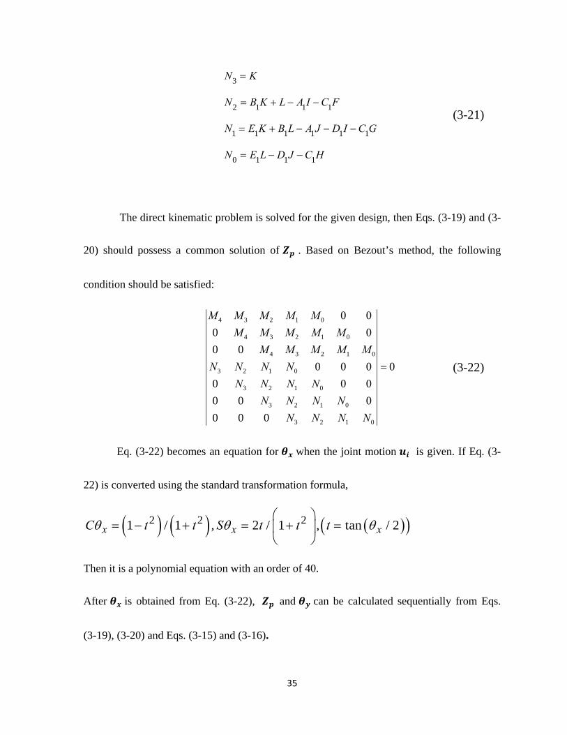
The direct kinematic problem is solved for the given design, then Eqs. (3-19) and (3-
20) should possess a common solution of . Based on Bezout’s method, the following
condition should be satisfied:
4 3 2 1 0
4 3 2 1 0
4 3 2 1 0
3 2 1 0
3 2 1 0
3 2 1 0
3 2 1 0
0 0
0 0
0 0
0 0 0 0
0 0 0
0 0 0
0 0 0
M M M M M
M M M M M
M M M M M
N N N N
N N N N
N N N N
N N N N
(3-22)
Eq. (3-22) becomes an equation for when the joint motion is given. If Eq. (3-
22) is converted using the standard transformation formula,
2 2 21 / 1 , 2 / 1 , tan / 2x x xC t t S t t t
Then it is a polynomial equation with an order of 40.
After is obtained from Eq. (3-22), and can be calculated sequentially from Eqs.
(3-19), (3-20) and Eqs. (3-15) and (3-16).
36
3.4 Jacobian Matrix
Each of the kinematic chains connecting the base to the platform can be taken as a
serial mechanism and a Hooke joint can be replaced by two orthogonal revolute joints in the
present study.
Presented in Figures 2.4 and 2.5, this three-degree-of-freedom mechanism consists of
four kinematic chains, including three variable length legs with identical topology and one
passive constraining leg, connecting the base to a moving platform. In this 3-DOF parallel
mechanism, the kinematic chains associated with the three identical legs (links) are
connected to the base platform with a universal joint, an actuated prismatic joint and a
spherical joint attached to the moving platform. The fourth chain connecting the fixed base
center to the moving platform center is a passive constraining leg and has a different
architecture from the other three identical chains. It consists of a prismatic joint attached to
the fixed base and a universal joint attached to the moving platform. This last leg is used to
constrain the motion of the platform to only three degrees of freedom.
37
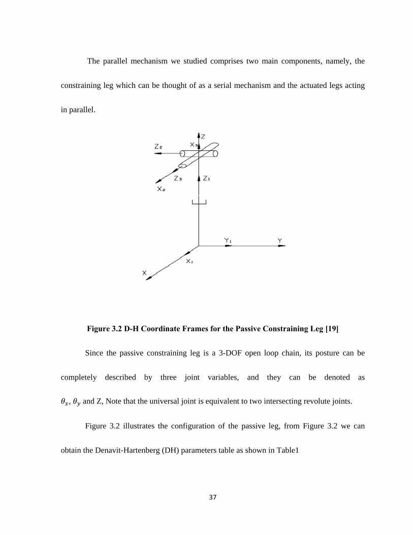
The parallel mechanism we studied comprises two main components, namely, the
constraining leg which can be thought of as a serial mechanism and the actuated legs acting
in parallel.
Figure 3.2 D-H Coordinate Frames for the Passive Constraining Leg [19]
Since the passive constraining leg is a 3-DOF open loop chain, its posture can be
completely described by three joint variables, and they can be denoted as
, and Z, Note that the universal joint is equivalent to two intersecting revolute joints.
Figure 3.2 illustrates the configuration of the passive leg, from Figure 3.2 we can
obtain the Denavit-Hartenberg (DH) parameters table as shown in Table1

38
i
0 0 0 0 0
1 0 Z 90° 0
2 0 0 90°
3 0 0 0
Table 1: DH Parameters for the Passive Constraining Leg of 3-DOF Mechanism
Considering the passive constraining leg, for 3-DOF mechanism we can write
1 1 , 3n n n J θ t (3-23)
Where is the twist of the platform, with the angular velocity of the platform
and
n+1 n+1,1 n+1,nθ = θ θ
(3-24)
is the joint velocity vector associated with the constraining leg. Matrix is the Jacobian
matrix of the constraining leg considered as a serial n-DOF mechanism, which can be
expressed as (Angeles 1997)
1,1 1,1
1, 1,1, 1, 3
n n nn
n n n nn n n nnr r
e eJ e e
(3-25)

39
Here ir is the vector connecting the origin of frame ib to the origin of the platform
frame. It is important to note that if the pair is a revolute joint, then the column
of , noted , can be written as
i
iii r
eeJ (3-26)
On the other hand, if the pair is a prismatic joint, then the and the
links have the same angular velocity, for a prismatic joint does not have any rotation, then the
column of changes to
0eJ
iii r
(3-27)
Here if we take base frame as frame 0, and defined 0, 0, and then
4 0
= 1Q (3-28)
Where is the rotation matrix from the fixed reference (base-platform) to the passive leg
and then we have
41 4040
= Qe e (3-29)
41 4040 41
= Q Qe e (3-30)
42 4040 41 42
= Q Q Qe e (3-31)
40
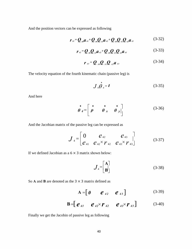
And the position vectors can be expressed as following
41 41 42 4340 40 41 40 41 42
= + +Q Q Q Q Q Qa a ar (3-32)
42 42 4340 41 40 41 42
= +Q Q Q Q Qa ar (3-33)
43 4340 41 42
= Q Q Q ar (3-34)
The velocity equation of the fourth kinematic chain (passive leg) is
4 4J
t (3-35)
And here
4 x yρθ θ θ (3-36)
And the Jacobian matrix of the passive leg can be expressed as
42 43
442 4341 42 43
0 e eJ e e er r
(3-37)
If we defined Jacobian as a 6 3 matrix shown below:
4
A
BJ
(3-38)
So A and B are denoted as the 3 3 matrix defined as
A 4 2 4 30 e e (3-39)
B 42 4341 42 43e e er r (3-40)
Finally we get the Jacobin of passive leg as following

41
0 0 sin( )
0 1 0
0 0 cos( )
0 0 0
0 0 0
1 0 0
x
x
4J (3-41)
According to the principle of virtual work, we have
T Tτ ρ w t (3-42)
Here τ is a vector of the actuator forces applied at each joint and w is the wrench,
which is the torque and force, applied to the moving platform. It is assumed that no
gravitational forces act on any of the intermediate links. Consequently, we have
where n and f are respectively the external torque and force applied to the
platform.
Rearranging Eq. (3-9) and substituting it into Eq. (3-42), we obtain
T TP J t twτ (3-43)
Now, substituting Eq. (3-35) into Eq. (3-43), we have
4 4 4 4T T
pJ J θ J θwτ (3-44)
The latter equation must be satisfied for the arbitrary values of 4θ and hence, we can write
4 4
T Tp J J J w (3-45)
42
The latter equation relates the actuator forces, which are applied to the end-effector in
static mode, to the Cartesian wrench w. Since all links are assumed to be rigid, the
compliance of the mechanism will be induced solely by the compliance of the actuators. An
actuator compliance matrix, C, is therefore defined as
C τ ρ (3-46)
Where τ is the vector of the actuated joint forces and ρ is the induced joint
displacement. Matrix C is a (3x3) diagonal matrix whose diagonal entry represents the
compliance of the actuator.
Now, Eq. (3-43) can be rewritten as
4 4( ) T T
p J J Jτ w (3-47)
The substitution of Eq. (3-47) into Eq. (3-46) then leads to
4 4( ) T T
p C J J Jρ w (3-48)
Moreover, for a vector representing minor displacement, ρ , Eq. (3-48 )can be written as
Jρ c (3-49)
Where C is a vector representing small Cartesian displacement and rotation, is defined as
T
T T
c p α (3-50)
Here, α is the change of orientation,
43
( )Tv e c t α Q Q (3-51)
Here Q is the variation of the orientation and ( )Tvect QQ is the linear invariant
vector of its matrix.
Similarly, for small displacements, Eq. (3-35) can also be written, as
4 4 J θ c (3-52)
Here 4θ is a vector representing minor variations of the passive leg’s joint coordinates.
Substituting Eq. (3-49) into Eq. (3-48),
4 4( ) T Tp p
J C J J Jc w (3-53)
Substituting Eq. (3-52) into Eq. (3-53),
4 4 4 4( ) T T
p p J J θ C J J J w (3-54)
Then, multiplying both sides of Eq. (3-54) by 14 )( JJ ,
14 4 4 4
( ) ( ) T Tp p
θ J J C J J J w (3-55)
and finally, multiplying both sides of Eq. (3-55) by 4J ,
14 4 4 4( ) ( ) T T
p p J J J C J J J wc (3-56)
Hence, the Cartesian compliance matrix becomes
14 4 4 4
( ) ( ) T Tp pc
C J J J C J J J (3-57)
with
44
c C wc (3-58)
Here cC is a symmetrical, positive, semi-definite (6x6) matrix, as expected.
3.5 Stiffness Modeling
Stiffness is one of the most important consideration facts in the design of parallel
kinematic manipulator. After we get the stiffness result of the structure, the next step is
design optimization. The stiffness of a parallel kinematic manipulator is given by its system
stiffness matrix. As in the stiffness model of this PKM, we consider the structure frames and
the links are rigid bodies, so the Cartesian stiffness matrix K c is opposite the Cartesian
compliance matrix cC . So from the Eq. (3-57) we got following:
In this case we fixed the moving platform in certain angle in x –axis, and use the design
kinematic parameter which shown in Table 2. We got stiffness map in following figures;
11 14 4 4 4( ) ( )C J J J C J J JT T
c p p
Kc

45
30° 90° 150° i 1,2,3
30° 90° 150° i 1,2,3
50 mm
25 mm
120 mm i 1,2,3
50°
Spherical Joint 40° 40°
Universal Joint 50° 50°
Prismatic Joint
Passive Link
50 mm
Table 2 Three Action Legs Kinematic Parameters
Figure 3.3 Stiffness in X axis (a)
46
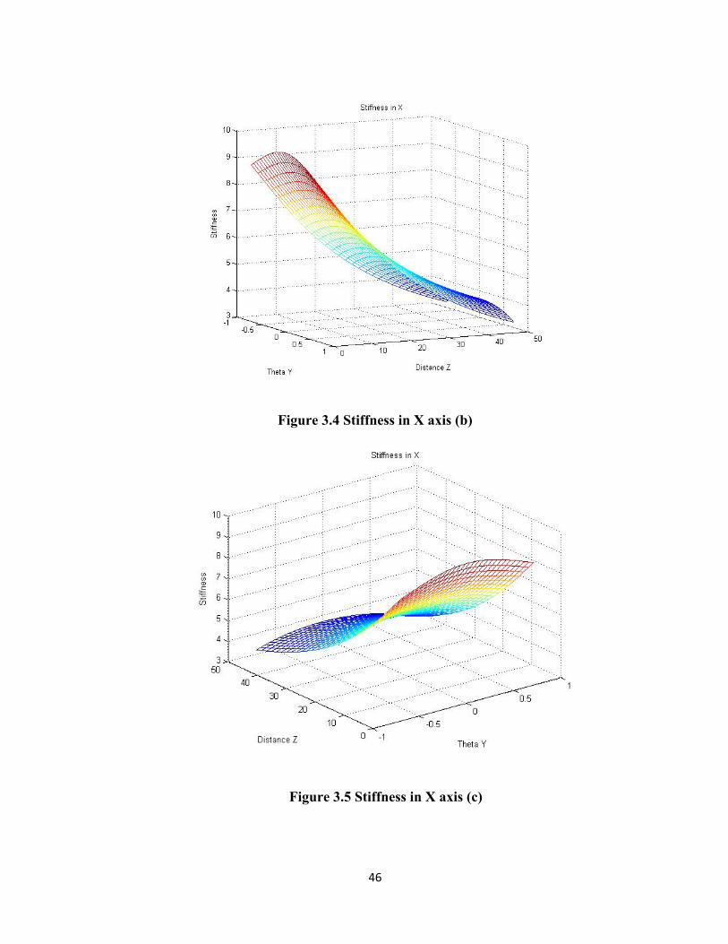
Figure 3.4 Stiffness in X axis (b)
Figure 3.5 Stiffness in X axis (c)
47
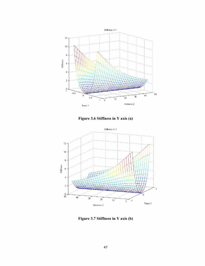
Figure 3.6 Stiffness in Y axis (a)
Figure 3.7 Stiffness in Y axis (b)

48
Figure 3.8 Stiffness in Y axis (c)
Figure 3.9 Stiffness in Z axis (a)
49
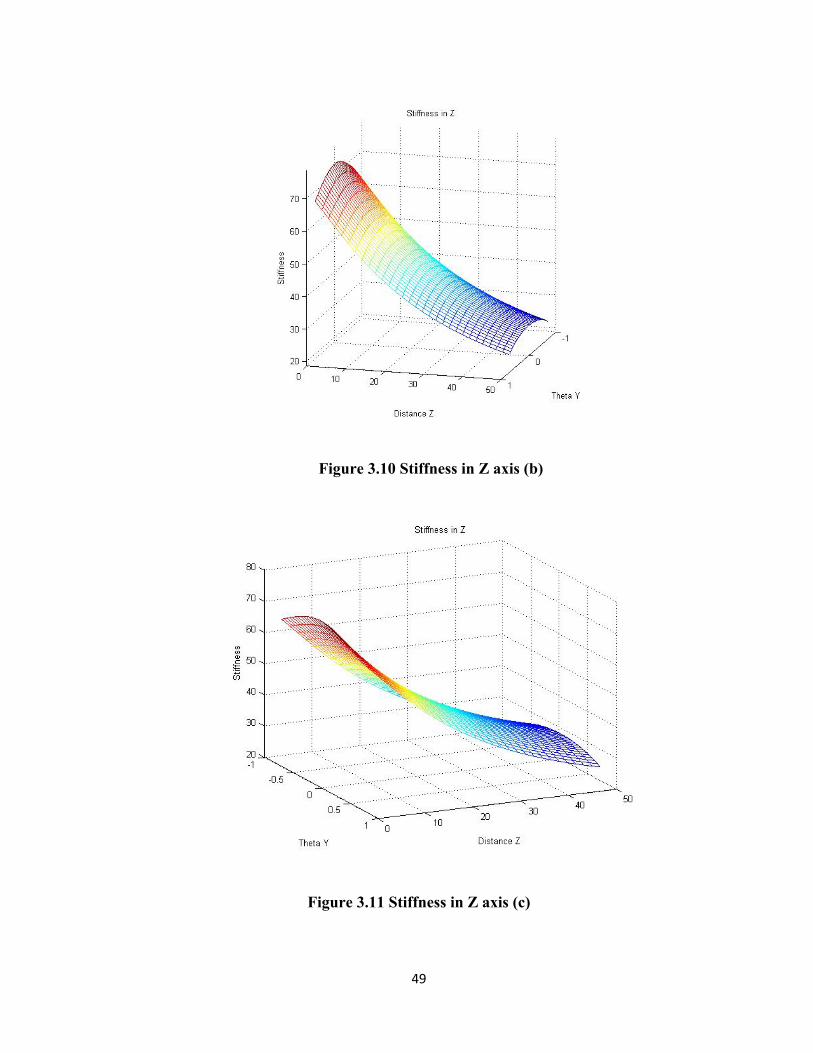
Figure 3.10 Stiffness in Z axis (b)
Figure 3.11 Stiffness in Z axis (c)
50
3.6 Conclusion
From above stiffness mesh graphs, Figure 3.3 to Figure 3.5 show the stiffness in X
axis with different view angle, same as Figure 3.6 to Figure 3.8 shows the stiffness in Y axis.
Figure 3.9, Figure 3.10 and Figure 3.11 shows the stiffness in Z axis. For stiffness in X axis,
one can conclude that stiffness is decreased when the magnitude of Z coordinates increase,
and also stiffness is symmetrical along the Y axis. For stiffness in Y axis, it reaches the
maximum values at absolute 1Y point, and has symmetry along Y axis. Also the
maximum points are located at Z coordinate's small value point. For the stiffness in Z axis,
the main change of the stiffness is along with Z coordinate, there is not much change when X
and Y value change.
This parallel kinematic manipulator (PKM) with three active kinematic chains and a
passive leg has improved precision and stiffness maps by:
Providing drive and actuation of each active kinematic chain by devices secured
rigidly to a support structure so that only a fixed length leg of the chain is
suspended.
Driving the fixed length leg of the active kinematic chain to move in a direction
oblique to a direction of the fixed length leg.

51
Providing a prismatic jointed leg that is rigidly secured to the base structure and
coupled by an effectively universal joint to the motion platform.

52
Chapter 4
Kinematic Modeling of 3-DOF Micro
Motion Manipulator with Actuation
Redundancy
4.1 CAD Modeling of the 3-DOF Micro Motion
Manipulator with Actuation Redundancy
The word redundant is commonly used to mean "exceeding what is necessary or
normal”, or extra what they needs. There are mainly two different types of redundancy for
parallel manipulators: a) kinematic redundancy and b) actuation redundancy. A parallel
manipulator is to be said to be kinematic redundant manipulator when mobility of the
mechanism is greater than the required degrees of freedom of the moving platform. On the
other hand, a parallel manipulator is called redundantly actuated manipulator when the
number of actuators is great than the mobility of the mechanism. It is believed that
redundancy can improve the ability and the performance of parallel manipulator [27] and
53
[28]. The reason we used the redundant mechanisms is that it can solve the singularity
problem, and improve the stiffness of the structure.
In the chapter 3 we have solved the kinematic problem of 3-DOF micro motion
parallel manipulator. In this chapter, we will follow the same procedure, and go on to discuss
parallel manipulator which has actuation redundancy. Normally actuation redundancy is only
applied to the closed-link mechanisms. However, singularity is a common problem in parallel
mechanisms. We will show that the behavior of singularity of parallel mechanisms can be
more complicated than that of serial ones. However, it is not clear whether singularity will
bring problems to kinematics, dynamics or other characteristics and what the result will be
when parallel mechanisms fall into the neighborhood of a singularity. Thus, we propose that
the greatest advantage of actuation redundancy is avoiding the singularity of the parallel
manipulator and increasing the stiffness of the structure.
54
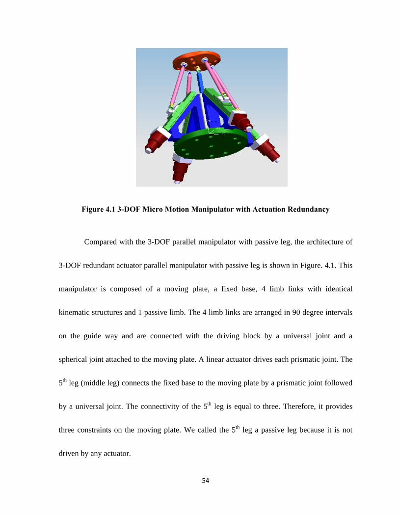
Figure 4.1 3-DOF Micro Motion Manipulator with Actuation Redundancy
Compared with the 3-DOF parallel manipulator with passive leg, the architecture of
3-DOF redundant actuator parallel manipulator with passive leg is shown in Figure. 4.1. This
manipulator is composed of a moving plate, a fixed base, 4 limb links with identical
kinematic structures and 1 passive limb. The 4 limb links are arranged in 90 degree intervals
on the guide way and are connected with the driving block by a universal joint and a
spherical joint attached to the moving plate. A linear actuator drives each prismatic joint. The
5th leg (middle leg) connects the fixed base to the moving plate by a prismatic joint followed
by a universal joint. The connectivity of the 5th leg is equal to three. Therefore, it provides
three constraints on the moving plate. We called the 5th leg a passive leg because it is not
driven by any actuator.
55
As shown in Figure 4-1, this parallel manipulator include the universal joint of the
passive link, located on the moving platform rather than the base platform, so the motions
along x and y translations and Z rotation are eliminated.
As in the previous chapter, the reference point on the moving platform has uncoupled
motion with X and Y rotations and Z translation. The proposed manipulator has three
platforms: base platform , middle platform , and moving
platform . The base platform is fixed on the ground. The middle platform is used to
support guide-way of actuated links .The moving platform is used to mount a tool.
The passive link is installed between the middle platform and the moving platform. Actuated
links are connected to the moving platform by a spherical joint (ball joint) at , and to
a slider connected to the active ball screw by a universal joint at . The passive link with a
prismatic joint is fixed on the middle platform at one end, and connected to the end-effector
platform by a universal joint at the other end.
Following parameters define other details of the structure:
The angle ( i =1,2,3,4) between and ,
The angle ( i=1,2,3,4) between and ,
The distance from on the base platform is ,
56
The distance from the end-effector platform is ,
The angle of a guide-way γ,
The length of an active link , and
The offset of the spherical joints on the platform .
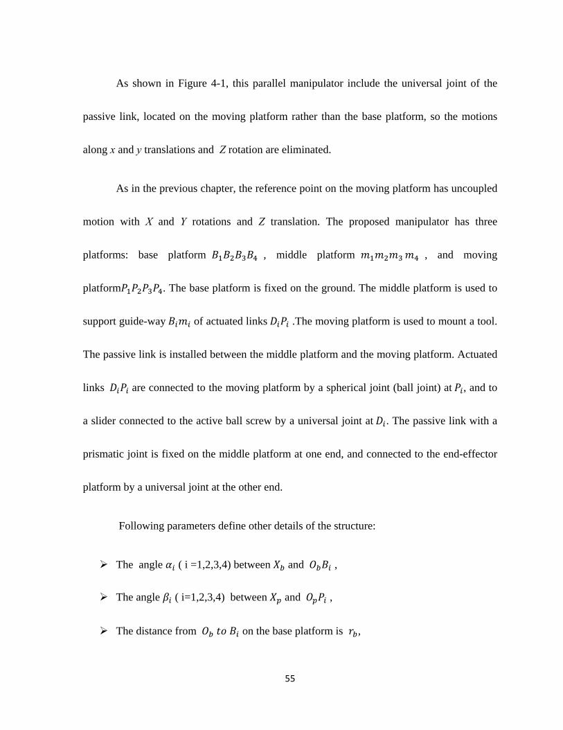
As shown in Figure 4.2, we also use same two coordinate systems,
and , which are attached to the end-effector and base platform, respectively.
For the origin of the end-effector, its translational motions along and , and rotational
motion along , are eliminated because of the usage of the passive leg.
Figure 4.2 Schematic of 3-DOF Micro Motion Manipulator with Actuation
Redundancy
57
4.2 Inverse Kinematics
The position vector of points of and i iP B with respect to the coordinate frames
a n d P b , respectively, can be written as
1,2,3,4
1,2,3,4
cos , sin , 0 ,
cos , sin , 0 ,
Ta ai i
Ti ib b
i
i
r r
r r
pi
bi
P
B (4-1)
Where ar and br are the length of the iO P and ' iOB , respectively, angle i is
measured from the x axis to the line iO Pand is equal to the x axis to the line 'iO B ,
0°, 90°, 180°, 270° 1,2,3,4 .
To facilitate the analysis, a position vector, is used to define the position
of the moving platform,
, ,T
x y zp p p BP (4-2)
And a rotation matrix, PBR , is used to define the orientation of the moving platform with
respect to the fixed base,
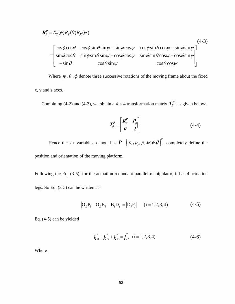
58
( ) ( ) ( )
cos cos cos sin sin sin cos cos sin cos sin sin
= sin cos sin sin sin cos cos sin sin cos cos sin
sin cos sin cos cos
YzR R Rx
PBR
(4-3)
Where , , denote three successive rotations of the moving frame about the fixed
x, y and z axes.
Combining (4-2) and (4-3), we obtain a 4 4 transformation matrix PBT , as given below:
P
P B pB
R PT
0 1 (4-4)
Hence the six variables, denoted as , , , , ,T
x y zp p p P , completely define the
position and orientation of the moving platform.
Following the Eq. (3-5), for the actuation redundant parallel manipulator, it has 4 actuation
legs. So Eq. (3-5) can be written as:
O P O B B D D P 1, 2,3, 4i i i i i ib b i (4-5)
Eq. (4-5) can be yielded
2 2 2 2
1 2 3, ( 1,2,3,4)
i i i iik k k l (4-6)
Where
59
1
2
3
bp i ii bi
bp i ii bi
bp ii i
k l u c c
k l u c s
k u s
x
y
z
(4-7)
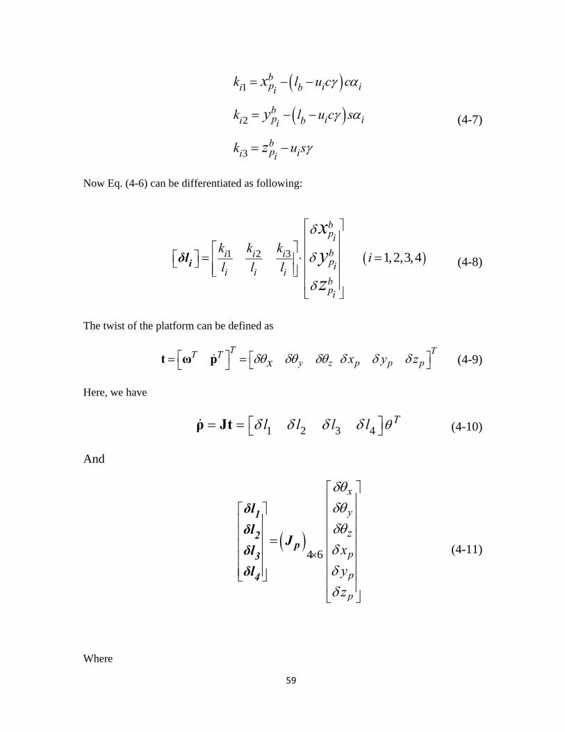
Now Eq. (4-6) can be differentiated as following:
1 2 3 1,2,3,4
bpi
bi i ipi
i i ibpi
k k ki
l l l
xyz
iδl (4-8)
The twist of the platform can be defined as
T TT T
y z p p px y zx t ω p (4-9)
Here, we have
1 2 3 4Tl l l l ρ Jt (4-10)
And
4 6
x
y
p
p
p
z
x
y
z
1
2p
3
4
δl
δlJ
δl
δl
(4-11)
Where
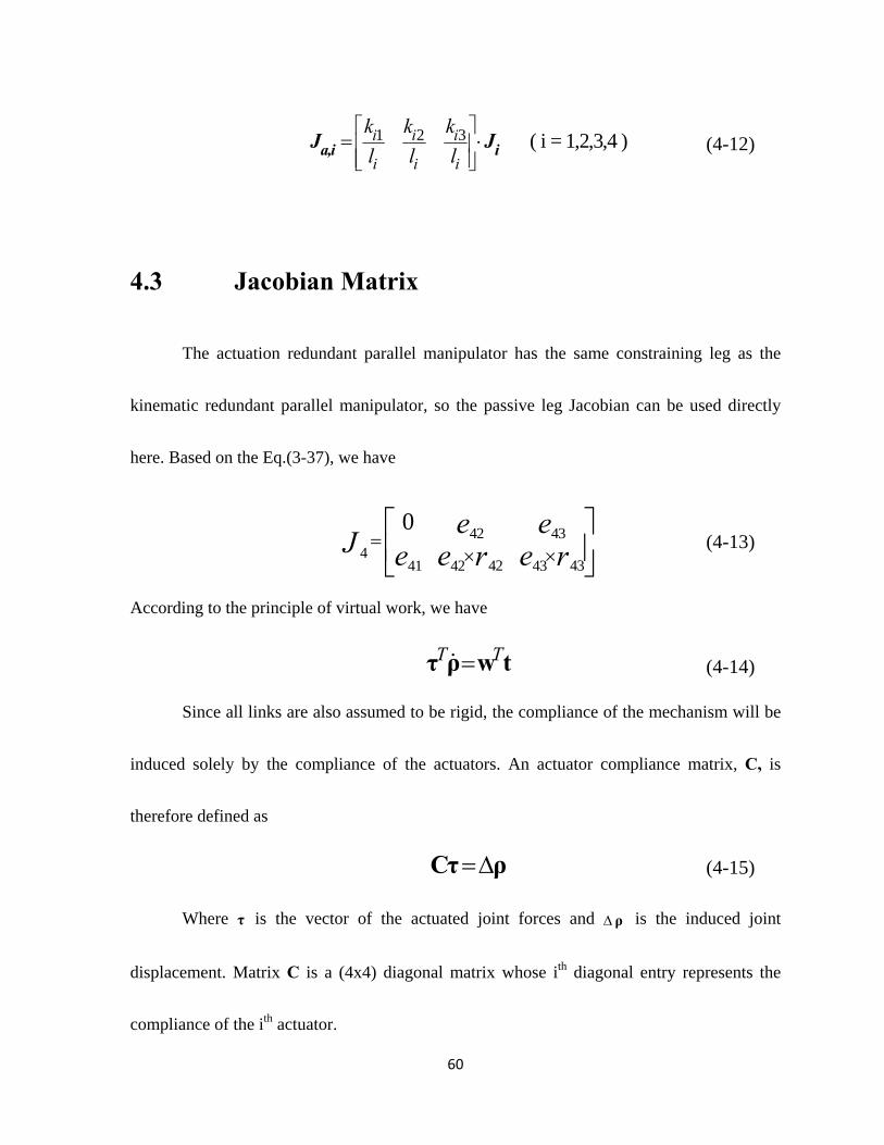
60
1 2 3 ( i = 1,2,3,4 )i i i
i i i
k k k
l l l
a,i iJ J (4-12)
4.3 Jacobian Matrix
The actuation redundant parallel manipulator has the same constraining leg as the
kinematic redundant parallel manipulator, so the passive leg Jacobian can be used directly
here. Based on the Eq.(3-37), we have
42 434
42 4341 42 43
0 e eJ e e er r
(4-13)
According to the principle of virtual work, we have
T Tτ ρ w t (4-14)
Since all links are also assumed to be rigid, the compliance of the mechanism will be
induced solely by the compliance of the actuators. An actuator compliance matrix, C, is
therefore defined as
Cτ ρ (4-15)
Where τ is the vector of the actuated joint forces and ρ is the induced joint
displacement. Matrix C is a (4x4) diagonal matrix whose ith diagonal entry represents the
compliance of the ith actuator.
61
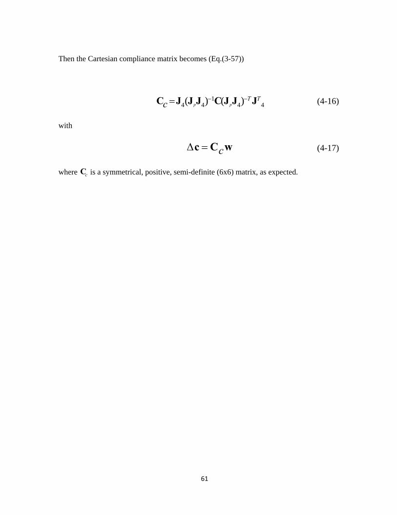
Then the Cartesian compliance matrix becomes (Eq.(3-57))
14 4 4 4( ) ( )p p
T Tc
C J J J C J J J (4-16)
with
c c C w (4-17)
where cC is a symmetrical, positive, semi-definite (6x6) matrix, as expected.

62
4.4 Stiffness Modeling
In order to compare between the two parallel kinematic manipulators, the same
parameters have been used in this thesis to calculate their stiffness. We also fixed the moving
plate in x axis certain angle and got the stiffness results in X, Y, and Z coordination
directions.
0° 90° 180° 270° i 1,2,3,4
0° 90° 180° 270° i 1,2,3,4
50mm
25mm
120 mm i 1,2,3,4
50°
Spherical Joint 40° 40°
Universal Joint 50° 50°
Prismatic Joint
Passive Link
50 mm
Table 3 Redundant 3-DOF Mechanism with the Passive Leg Kinematic Parameters
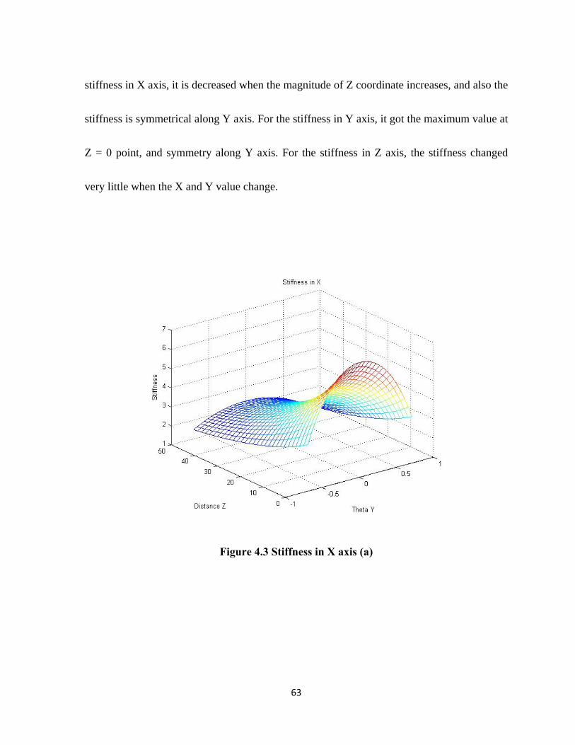
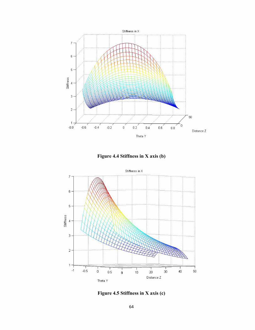
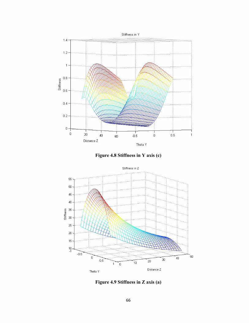
In the following stiffness mesh graphs, Figure 4.3 to Figure 4.5 show the stiffness in
X axis with different view angle, same as Figure 4.6 to Figure 4.8 show the stiffness in Y
axis. Figure 4.9 to Figure 4.11 show the stiffness in Z axis. One can conclude that for the
63
stiffness in X axis, it is decreased when the magnitude of Z coordinate increases, and also the
stiffness is symmetrical along Y axis. For the stiffness in Y axis, it got the maximum value at
Z = 0 point, and symmetry along Y axis. For the stiffness in Z axis, the stiffness changed
very little when the X and Y value change.
Figure 4.3 Stiffness in X axis (a)
64
Figure 4.4 Stiffness in X axis (b)
Figure 4.5 Stiffness in X axis (c)

65
Figure 4.6 Stiffness in Y axis (a)
Figure 4.7 Stiffness in Y axis (b)
66
Figure 4.8 Stiffness in Y axis (c)
Figure 4.9 Stiffness in Z axis (a)

67
Figure 4.10 Stiffness in Z axis (b)
Figure 4.11 Stiffness in Z axis (c)
68
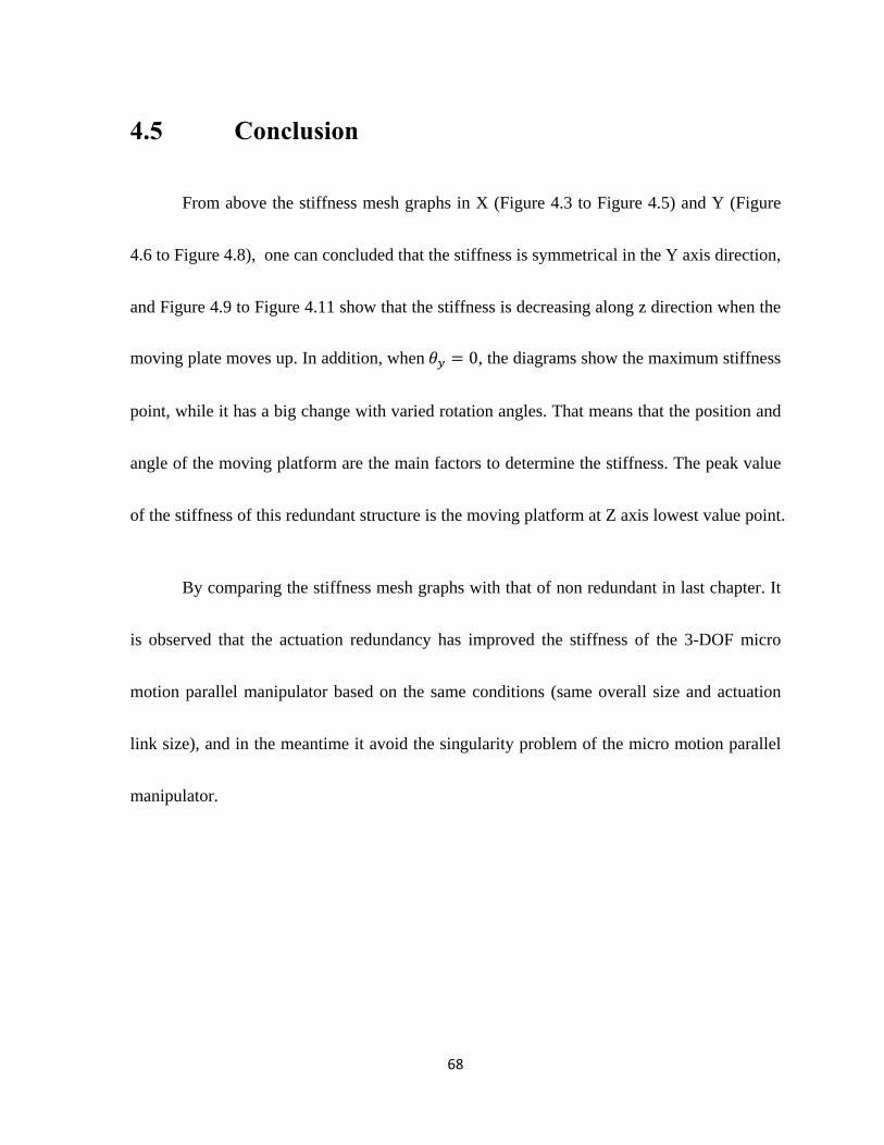
4.5 Conclusion
From above the stiffness mesh graphs in X (Figure 4.3 to Figure 4.5) and Y (Figure
4.6 to Figure 4.8), one can concluded that the stiffness is symmetrical in the Y axis direction,
and Figure 4.9 to Figure 4.11 show that the stiffness is decreasing along z direction when the
moving plate moves up. In addition, when 0, the diagrams show the maximum stiffness
point, while it has a big change with varied rotation angles. That means that the position and
angle of the moving platform are the main factors to determine the stiffness. The peak value
of the stiffness of this redundant structure is the moving platform at Z axis lowest value point.
By comparing the stiffness mesh graphs with that of non redundant in last chapter. It
is observed that the actuation redundancy has improved the stiffness of the 3-DOF micro
motion parallel manipulator based on the same conditions (same overall size and actuation
link size), and in the meantime it avoid the singularity problem of the micro motion parallel
manipulator.
69
Chapter 5
Design Optimization
5.1 Introduction of Optimization Methods
The Genetic Algorithm (GA) is an excellent method for solving both constrained and
unconstrained optimization problems. This algorithm repeatedly modifies a population of
individual solutions based on the principle of natural selection. In each step, the Genetic
Algorithm selects random individuals from the current population as parents and uses them
to produce children for the next generation. Throughout each generation, the population
progresses towards an optimal solution. The Genetic Algorithm can be applied to solve a
variety of optimization problems, including problems where the objective function is linear,
nonlinear, continuous, discontinuous, differentiable and non-differentiable.
The advantages of the Genetic Algorithm (GA) can be summarized as follows:
Optimizes with continuous or discrete variables
Does not require derivative information
Simultaneously searches from a wide sampling of the cost surface
70
Deals with a large number of variables
Is appropriate for parallel computers
Optimizes variables with extremely complex cost surfaces, especially variables that
can jump out of a local minimum
Provides a list of optimum variables rather than just a single solution
In this thesis, the GA is used for optimizing the global stiffness of the 3-DOF micro-
motion parallel manipulator and the 3-DOF micro-motion parallel manipulator with actuation
redundancy.
71
5.2 Implementation of Optimization
5.2.1 Optimization of 3-DOF Micro Motion Parallel
Manipulator
n this thesis, the stiffness of a parallel manipulator is expressed by a 3 × 3 matrix. In
this case, the GA is applied for optimizing the global stiffness (val) of the micro-motion
parallel manipulator. The diagonal elements of the parallel manipulator stiffness matrix
represent the manipulator’s pure stiffness in each direction [20] (Zhang 2000). To obtain the
maximum stiffness in each direction, the following objective function, which is called the
fitness function for the GA, is used.
11 22 33val k k k (5-1)
where ( 1, 2, 3)k iii represents the diagonal elements of the 3-DOF parallel manipulator’s
stiffness matrix. Subsequently, the next objective is to maximize val in the GA.
Parameters need to be set up before the GA is utilized. First, the fitness function,
which is the function of the objective being optimized, should be created. In this case, the
fitness function is represented in Eq. (5-1). In order to maximize f(x), -f(x) can be minimized,

72
since the point at which the minimum of -f(x) occurs is the same as the point at which f(x) is
maximized.
Secondly, the number of variables should be determined. In this structure, there are
three design parameters, which are considered to be the optimization variables. Specifically,
they include the length of the leg “l”, the dimension of the end-effectors “r ” and the base
dimension“r ”. Furthermore, these values in Eq. (5-2) also contribute to the val . Therefore,
the vector of optimization variables is
[ , , ]a br r l (5-2)
and their bound conditions are
[18.75, 31.25] mm, [37.5, 62.5] mm, l[90, 150] mm,
The following figure displays a plot of the best and the mean values of the fitness
function at each generation. The points at the bottom of the plot denote the best fitness values,
while the points above them denote the mean of the fitness values in each generation. Also, at
the top of the figure, the plot displays the best and the mean values for the current generation.
73
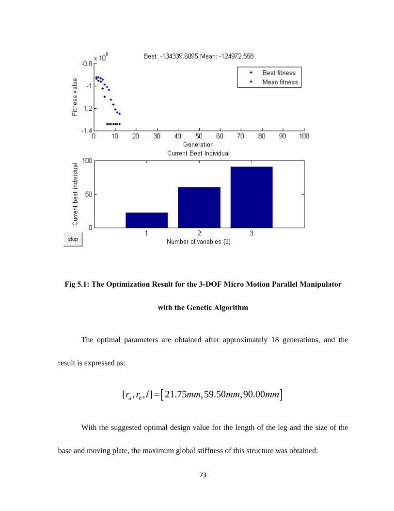
Fig 5.1: The Optimization Result for the 3-DOF Micro Motion Parallel Manipulator
with the Genetic Algorithm
The optimal parameters are obtained after approximately 18 generations, and the
result is expressed as:
[ , , ] 21.75 ,59.50 ,90.00a br r l mm mm mm
With the suggested optimal design value for the length of the leg and the size of the
base and moving plate, the maximum global stiffness of this structure was obtained:
74
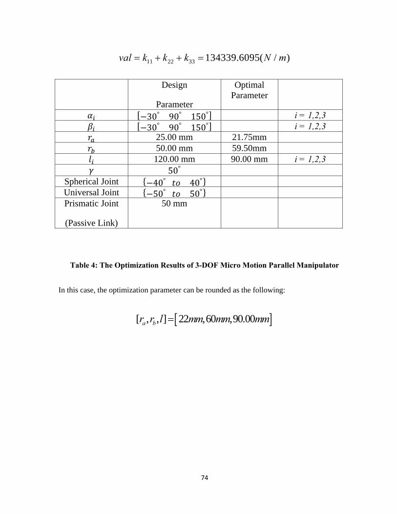
11 22 33 134339.6095( / )val k k k N m
Design
Parameter
Optimal Parameter
30° 90° 150° i = 1,2,3 30° 90° 150° i = 1,2,3 25.00 mm 21.75mm 50.00 mm 59.50mm 120.00 mm 90.00 mm i = 1,2,3 50°
Spherical Joint 40° 40° Universal Joint 50° 50° Prismatic Joint
(Passive Link)
50 mm
Table 4: The Optimization Results of 3-DOF Micro Motion Parallel Manipulator
In this case, the optimization parameter can be rounded as the following:
[ , , ] 22 ,60 ,90.00a br r l mm mm mm

75
5.2.2 Optimization of 3-DOF Micro Motion Parallel
Manipulator with Actuation Redundancy
With this structure, the same concept was used as with the 3-DOF micro-motion
parallel manipulator in the previous section. The diagonal elements of the matrix represent
the pure stiffness of the 3-DOF micro-motion parallel manipulator with actuation redundancy
in each direction [20]. To obtain the maximum stiffness in each direction, the following
objective function, which is also called the fitness function in the GA, can be written, which
yields
11 22 33 44val k k k k (5-3)
where ( 1, 2, 3,4)k iii represents the diagonal elements of the PKM’s stiffness
matrix. The next objective is to maximize val in the GA.
There are also three design parameters considered as optimization variables,
including the length of the leg “l”, the dimension of the end-effectors “r ” and the base
dimension“r ”. Additionally, these values in Eq. (5-2) also contribute to the val . Therefore,
the vector of optimization variables is expressed as
[ , , ]a br r l (5-4)
76
And their bound conditions are
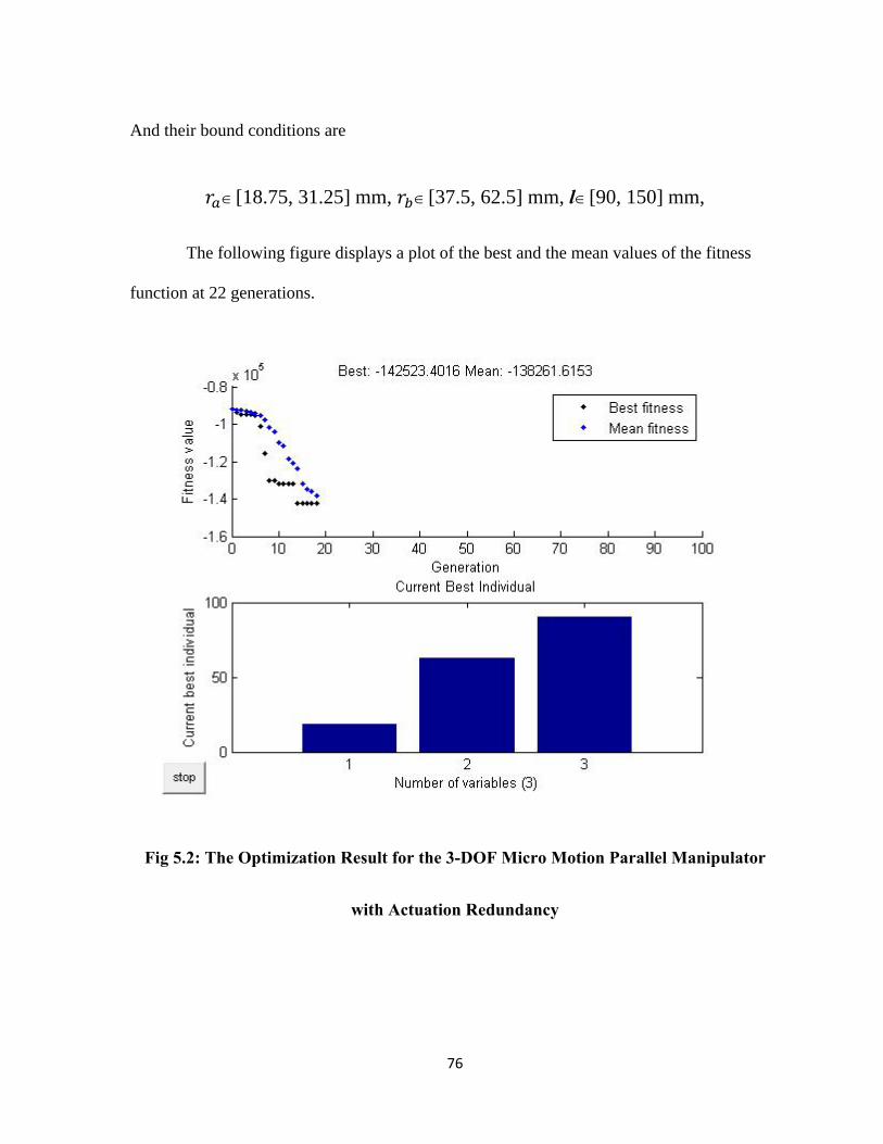
[18.75, 31.25] mm, [37.5, 62.5] mm, l[90, 150] mm,
The following figure displays a plot of the best and the mean values of the fitness
function at 22 generations.
Fig 5.2: The Optimization Result for the 3-DOF Micro Motion Parallel Manipulator
with Actuation Redundancy
77
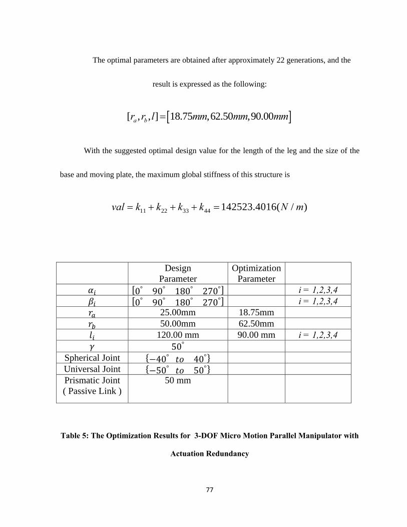
The optimal parameters are obtained after approximately 22 generations, and the
result is expressed as the following:
[ , , ] 18.75 ,62.50 ,90.00a br r l mm mm mm
With the suggested optimal design value for the length of the leg and the size of the
base and moving plate, the maximum global stiffness of this structure is
11 22 33 44 142523.4016( / )val k k k k N m
Design Parameter
Optimization Parameter
0° 90° 180° 270° i = 1,2,3,4 0° 90° 180° 270° i = 1,2,3,4 25.00mm 18.75mm 50.00mm 62.50mm 120.00 mm 90.00 mm i = 1,2,3,4 50°
Spherical Joint 40° 40° Universal Joint 50° 50° Prismatic Joint ( Passive Link )
50 mm
Table 5: The Optimization Results for 3-DOF Micro Motion Parallel Manipulator with
Actuation Redundancy
78
For the actual size prototyping model, the optimization parameter of the redundant
structure is expressed as:
[ , , ] 18.75 ,62.50 ,90.00a br r l mm mm mm
5.3 Conclusions
For the design optimization, the moving plate was fixed at a certain position,
which meant that , , and were at a certain volume, in order to determine the
dimensions of . , and and the maximum stiffness. Based on the positions of the
moving plate, the outcomes were likely to vary. Tables 4 and 5 show the optimization
results of the 3-DOF Micro-Motion Parallel Manipulator with 3 active legs and the 3-DOF
Micro-Motion Parallel Manipulator with Actuation Redundancy, which has 4 active legs.
These results demonstrated that with a similar design size, the stiffness of the redundant
structure is 6% greater than that of the non-redundant structure.

79
Chapter 6
Simulation and Comparisons
In this chapter, we conducted a Finite Element Analysis and a Dynamic Study. The
purpose of the FEA and the Dynamic Study is to improve the design of the structures and to
optimize the model size.
6.1 Finite Element Method Analysis
Finite element method (FEM) analysis plays an increasingly important role in
engineering practice, as it is relatively inexpensive and efficient in comparison with physical
experiments. Currently, FEM is utilized in almost all of the engineering fields, as it is a
powerful tool in predicting the ultimate loads and the complex failure modes of 3-D
structural members.

80
In this research, the purpose of FEM is to find the maximum and minimum stress
points. This section examines the three-dimensional solid models, which are developed using
Unigraphics NX6.
For the FEM conditions, the reasonable press force of 25N was applied to the moving
platform, and the maximum stress on the components was calculated. Subsequently, the
result can be exported as the stress, strain or displacement of the specific part of the structure.
In order to compare the two proposed structures, the geometric size of the manipulators was
made equal. From the FEM results, the maximum and minimum deformation areas were
found.

81
Figure 6.1: Moving Plate FEM Simulation of 3-DOF Micro Motion Parallel
Manipulator with a Passive Leg
Figure 6.2: Moving Plate FEM Simulation of 3-DOF Micro Motion
Parallel Manipulator with Actuation Redundancy

82
Figure 6.3: Moving Link FEM Simulation of 3-DOF Micro Motion Parallel
Manipulator with Actuation Redundancy
Figure 6.4: Triangle Support FEM Simulation of 3-DOF Micro Motion Parallel
Manipulator
83
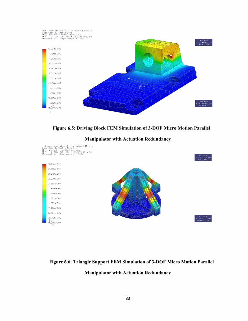
Figure 6.5: Driving Block FEM Simulation of 3-DOF Micro Motion Parallel
Manipulator with Actuation Redundancy
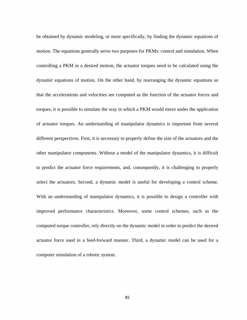
Figure 6.6: Triangle Support FEM Simulation of 3-DOF Micro Motion Parallel
Manipulator with Actuation Redundancy

84
For each manipulator, the same amount of force was applied to the moving platform,
achieving the maximum displacement, or deformation, of the triangle support. For the 3-DOF
micro-motion parallel manipulator, the triangle support resulted in a peak deformation of
9.225e-004mm, whereas for the 3-DOF micro-motion parallel manipulator with actuation
redundancy, the deformation was 3.170e-004mm. Furthermore, the deformation on the
moving platform was obtained for each manipulator. In this case, the 3-DOF micro-motion
parallel manipulator had a maximum deformation of 7.715e-0.003 mm, while the 3-DOF
micro-motion parallel manipulator with actuation redundancy had a maximum deformation
of 3.715e-005mm. Therefore, these results demonstrate that the 3-DOF micro-motion parallel
manipulator with actuation redundancy is much more robust than the 3-DOF micro-motion
parallel manipulator without redundancy.
6.2 Velocity and Acceleration Analysis
The dynamics of PKMs involve the science of studying the forces required to cause
motion. To accelerate a PKM from rest to a desired speed, or to decelerate it from a certain
speed to rest, a complex set of forces or torques must be applied by joint actuators. Therefore,
finding the relationships between the accelerations, velocities and positions of the end-
effector and the joint forces is the main task in this dynamic analysis. These relationships can
85
be obtained by dynamic modeling, or more specifically, by finding the dynamic equations of
motion. The equations generally serve two purposes for PKMs: control and simulation. When
controlling a PKM in a desired motion, the actuator torques need to be calculated using the
dynamic equations of motion. On the other hand, by rearranging the dynamic equations so
that the accelerations and velocities are computed as the function of the actuator forces and
torques, it is possible to simulate the way in which a PKM would move under the application
of actuator torques. An understanding of manipulator dynamics is important from several
different perspectives. First, it is necessary to properly define the size of the actuators and the
other manipulator components. Without a model of the manipulator dynamics, it is difficult
to predict the actuator force requirements, and, consequently, it is challenging to properly
select the actuators. Second, a dynamic model is useful for developing a control scheme.
With an understanding of manipulator dynamics, it is possible to design a controller with
improved performance characteristics. Moreover, some control schemes, such as the
computed torque controller, rely directly on the dynamic model in order to predict the desired
actuator force used in a feed-forward manner. Third, a dynamic model can be used for a
computer simulation of a robotic system.

86
In this section, we utilize Adams/View software to run the dynamic analysis.
Generally, Adams/View is used to perform the kinematic and dynamic simulations of a
multi-body mechanism. In this software, the motion of a rigid body is driven by motion at a
joint. Because the inverse kinematics can be presented in closed form, the motions at the
three prismatic joints between the slides and the three legs are defined and input according to
the position equations (3-3) and (4-3). The simulation result of the actuator force can be
output, and other kinematics and dynamic analysis, such as velocity, acceleration and
kinematic energy, can also be shown in Adams/View.
By applying Adams/View software to run the dynamic analysis, the displacement,
velocity, acceleration and instantaneous rotation center of the platform for the parallel
manipulator with three to four active links can be automatically solved and visualized, and
the velocity and acceleration simulation structures of the parallel manipulators can be created
similar to a 3-D sketch model. However, unlike a real 3-D solid model, when modifying the
size of the active links, the configurations of the velocity and acceleration simulation results
are varied accordingly, but all of the geometric and dimension constraints are always
maintained; thus, all mathematical relationships of the parallel manipulators are also retained.
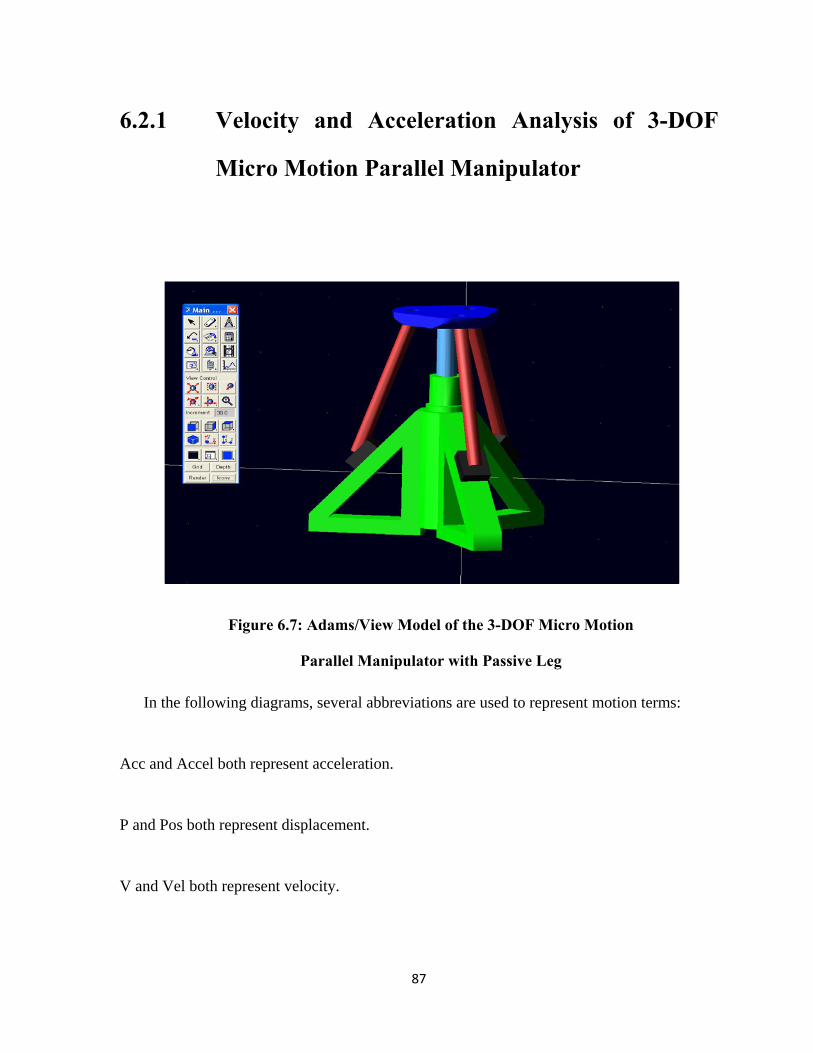
87
6.2.1 Velocity and Acceleration Analysis of 3-DOF
Micro Motion Parallel Manipulator
Figure 6.7: Adams/View Model of the 3-DOF Micro Motion
Parallel Manipulator with Passive Leg
In the following diagrams, several abbreviations are used to represent motion terms:
Acc and Accel both represent acceleration.
P and Pos both represent displacement.
V and Vel both represent velocity.

88
The following graphs are generated from Adams/View. In this simulation, 7 seconds
and 200-step simulations produce 4 sets of curves for the first 3-DOF micro-motion parallel
manipulator. Each graph represents a particular link or platform: Figure 6.8 is the result for
Link 1, Figure 6.9 shows Link 2, Figure 6.10 demonstrates the result for Link 3, and Figure
6.11 depicts the simulation result for the moving platform.
Figure 6.8: Displacements, Velocity, and Acceleration of Active Link 1

89
Figure 6.9: Displacements, Velocity, and Acceleration of Active Link 2
Figure 6.10: Displacements, Velocity, and Acceleration of Link 3
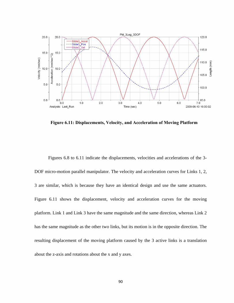
90
Figure 6.11: Displacements, Velocity, and Acceleration of Moving Platform
Figures 6.8 to 6.11 indicate the displacements, velocities and accelerations of the 3-
DOF micro-motion parallel manipulator. The velocity and acceleration curves for Links 1, 2,
3 are similar, which is because they have an identical design and use the same actuators.
Figure 6.11 shows the displacement, velocity and acceleration curves for the moving
platform. Link 1 and Link 3 have the same magnitude and the same direction, whereas Link 2
has the same magnitude as the other two links, but its motion is in the opposite direction. The
resulting displacement of the moving platform caused by the 3 active links is a translation
about the z-axis and rotations about the x and y axes.
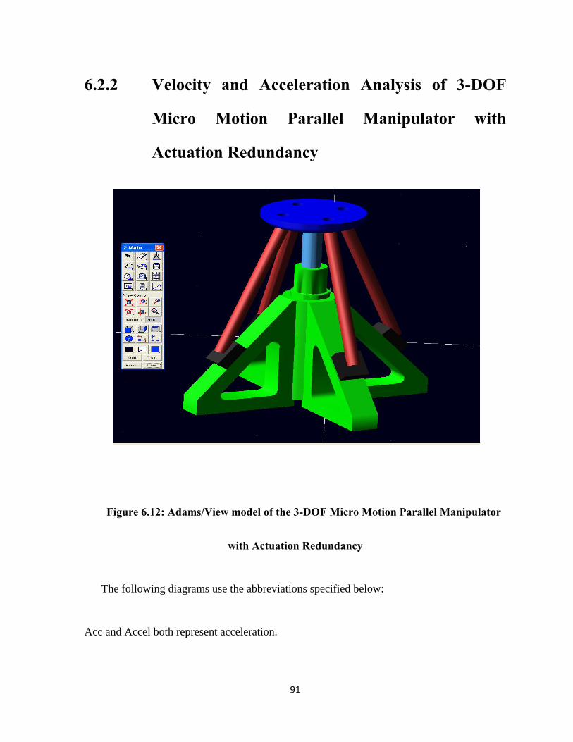
91
6.2.2 Velocity and Acceleration Analysis of 3-DOF
Micro Motion Parallel Manipulator with
Actuation Redundancy
Figure 6.12: Adams/View model of the 3-DOF Micro Motion Parallel Manipulator
with Actuation Redundancy
The following diagrams use the abbreviations specified below:
Acc and Accel both represent acceleration.
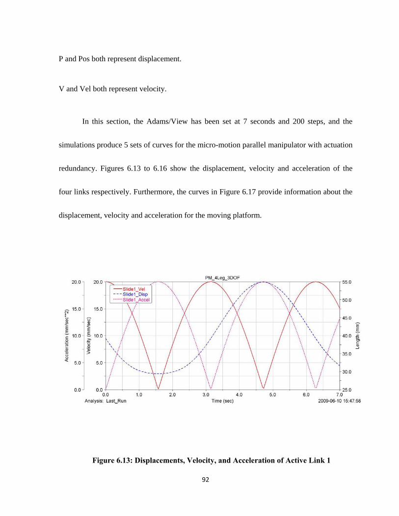
92
P and Pos both represent displacement.
V and Vel both represent velocity.
In this section, the Adams/View has been set at 7 seconds and 200 steps, and the
simulations produce 5 sets of curves for the micro-motion parallel manipulator with actuation
redundancy. Figures 6.13 to 6.16 show the displacement, velocity and acceleration of the
four links respectively. Furthermore, the curves in Figure 6.17 provide information about the
displacement, velocity and acceleration for the moving platform.
Figure 6.13: Displacements, Velocity, and Acceleration of Active Link 1
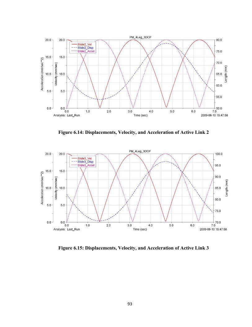
93
Figure 6.14: Displacements, Velocity, and Acceleration of Active Link 2
Figure 6.15: Displacements, Velocity, and Acceleration of Active Link 3

94
Figure 6.16: Displacements, Velocity, and Acceleration of Active Link 4
Figure 6.17: Displacements, Velocity, and Acceleration of Moving Platform
Figures 6.13 to 6.17 indicate the displacements, velocities and accelerations for the 3-
DOF micro-motion parallel manipulator with actuation redundancy. The displacements,
95
velocities and accelerations for the four links are very similar, since the links contain an
identical design and use the same actuators and these actuation links have been arranged in a
symmetrical position.
The last graph shows the displacements, velocity and acceleration of the moving
platform. While the velocity and acceleration of the moving platform is similar to that of the
active links, the displacement is different, as it depends on the moving directions of the
active links. The resulting displacement of the moving platform caused by the three active
links is a translation about the z-axis and rotations about the x and y axes.
The displacement, velocity and acceleration of both structures were compared, and
these two sets of graphs indicate that both results are very similar. Specifically, the curves of
the redundant structure are smoother than those of the non-redundant structure, and the
results of the redundant structure also show that decreasing the acceleration will reduce the
force that acts on active links and joints.

96
Chapter 7
Conclusions and Future Work
7.1 Conclusions
This thesis proposes two newly developed micro-motion 3-DOF parallel manipulators:
one of which is a 3-DOF micro-motion parallel manipulator, and another which is the 3-DOF
micro-motion parallel manipulator with actuation redundancy. Throughout the thesis, the
CAD models for the design have been created, the inverse kinematics for both structures
have been analyzed, and the Jacobian matrix has been derived. Additionally, stiffness models
and maps were presented, the optimization of global stiffness for the PKMs were performed
and the optimal design parameters have been suggested. Finally, the Finite Element Method
(FEM) analysis and the dynamic analysis have been performed for both structures. The
conclusions can be highlighted as follows:
The CAD models for both micro-motion 3-DOF parallel manipulators have been
created with Unigraphics NX6. They are designed and developed to perform the translation
97
along the z-axis and rotations about x and y axes. Their unique design eliminates side-effect
motions, so that they only exhibit pure 3-DOF motions, and it improves the stiffness of
mechanism by applying the passive link. Furthermore, the redundant structure eliminates the
singularity deficiency in the system. Both inverse kinematics have been successfully
examined, and the Jacobian matrix and velocity equations were fully derived. Lastly, the
research is also demonstrated by the study of kinematic and dynamic models.
The stiffness analysis section presents the stiffness models and mappings of the two
proposed manipulators. In comparison with the stiffness mesh graphs and contour maps, the
stiffness will increase as the z-coordinate value decreases. Specifically, it will reach its
maximum where the z-value obtains the smallest point. Moreover, the stiffness mappings are
symmetrical along the x or y axis due to the identical actuator links designs.
For the optimization of global stiffness, the optimal parameters are obtained for the 3-
DOF micro-motion parallel manipulator after 18 generations, and the optimal parameters for
the manipulator with actuation redundancy are obtained after approximately 22 generations.
In comparing the optimal parameters of the two manipulators, we found these values are very
close, except for the stiffness function Val, which is much larger for the redundancy structure.
Therefore, it is evident that the redundancy structure is superior to the non-redundancy
structure in terms of stiffness.

98
FEM analysis has been used to modify the design parameters in the research. The
FEM result for the main components of the two structures produced the maximum stress and
strain and the displacements or deformation. Additionally, these results demonstrated that at
the maximum stress and strain conditions, the displacements of the main components for the
redundant structure are much smaller than those for the non-redundant structure, thus
concluding that the redundant structure is more effective than the non-redundant structure.
The purpose of FEM analysis is to allow a modification of the parameters and to improve
structure for future applications.
Dynamics analysis is the science of studying the forces required for causing motion;
it plays an important role in the trajectory generation and control of parallel robots. In the
analysis of velocity and acceleration, the simulation results have been completed. The motion
equations of the two 3-DOF micro-motion parallel manipulators are derived using the
Lagrange Method for dynamic modeling, which can also be used for simulation and control
purposes. With the simulation results, the actuator force can be output and other kinematics
and dynamic analyses, such as velocity, acceleration and kinematic energy, can also be
shown in Adams/View.
99
7.2 Future Work
A prototyping model will be fabricated according to the optimization parameters.
More detailed calculations of dynamics will be performed, and the control system needs to be
designed and added to the framework. In particular, Matlab and Adams/View can be used in
dynamics studies to calculate the actuator force and other kinematics and dynamic
parameters. The enhanced structure optimization and some of the engineering drawings will
be revised and finalized for manufacturing.
100
Reference
[1] Cho, ChangHyun; Kang, Sungchul; Kim,Munsang; and Song ,Jae-Bok; “Macro-
Micro Manipulation with Visual Tracking and its Application to Wheel Assembly”
International Journal of Control, Automation, and Systems, vol., no.3,pp 461-468,
September 2005.
[2] Golda, Dariusz; Culepepper, Martin L; “SMALL-SCALE MICRO/ NANO-
MANIPULATORS IIN PRECISION ALIGNMENT AND POSITIONING”
[3] Liu, Dezhong; Xu, Yihua; Fei, Renyuan; “Study of an intelligent micro-
manipulator”Journal of Material Processing Technology 139(2003)77-80.
[4] Harachima Fumio “Integrated Micro-motion Systems: Micromachining, control,
and application”.
[5] Bang, Yongbong; Lee,Kyung-min; Kook,Juho; Lee, Wonseok; and Kim, In-su;
Micro Parts Assembly system With Micro Gripper”.
[6] Zubir, Mohd Nashrul Mohd; “Developemtn of a high precision flex-based
microgripper”Precision Enginering 33(2009) 362-270.
[7] Gilsinn, James D.; Damazo, Bradley N.; Silver, Richard; Zhou, Hui; “a Macro-
Micro System for a Scanning Tunneling Microscope”.
101
[8] Nomakuchi, Tamotsu “The speech keynote in The Eleventh international
Micromachine Nanotech Symposium”.
[9] Eijekl, Kees and Baba, Yoshinobu; “The speech keynote in The Eleventh
international Micromachine Nanotech Symposium”.
[10] Ouyang, P.R.; Tjiptoprodjo, R.C.; Zhang, W.J.; Yang, G.S.; “Micro-Motion Device
technology: The State of arts review” Int .Adv.Manuf Technol. DOI 10.1007/s001
[11] Zhang, Dan; Xu, Zhengyi; Mechefske, Chris M.; and Xi, Fengfeng “optimum
design of parallel kinematic toolheads genetic algorithms” Robotiica (2004)
volume 22. Pp. 77-84. ©2004 Cambridge University Press.
[12] Clavel R (1988) DELTA, “A fast robot with parallel geometry”. In: Proceedings of
the 18th International Symposium on Industrial Robots, Lausanne, Switzerland, 26–
28 April 1988, pp 91–100.
[13] Sternheim F (1987) “Computation of the direct and inverse kinematics model of the
Delta 4 parallel robot”. Roboter systeme 3:199–203.
[14] Lee, K, Shah DK (1987)”Kinematic analysis of a three degrees of freedom in-
parallel actuated manipulator”. In: Proceedings of the IEEE International
Conference On Robotics and Automation, Raleigh, NC, 31 March–3 April 1987, pp
345–350.

102
[15] Asada H, Cro Granito JA (1985) “Kinematic and static characterization of wrist
joints and their optimal design”. In: Proceedings of IEEE International Conference
on Robotics and Automation, St. Louis, MO, 25–28 March1985, pp 91–100.
[16] Gosselin, C; Hamel J (1994) “The agile eye: agile performance three degree of
freedom camera–orienting device.” In: Proceedings of the IEEE International
Conference on Robotics and Automation, San Diego, CA, 8–13 May 1994, pp 781–
786.
[17] Tsai, LW; Walsh, GC, Stamper R (1996) “Kinematics of a novel three DOF
translational platform”. In: Proceedings of the 1996 IEEE International Conference
on Robotics and Automation, Minneapolis, MN, 22–28 April 1996, pp 3446–3451.
[18] Joshi, SA; Tsai, LW (2003) “The kinematics of a class of 3-DOF, 4-legged parallel
manipulators”. Trans ASME 125:52-60.
[19] Zhang, Dan. "On stiffness improvement of the Tricept machine tool" Robotica
(2005) volume 2, pp.377-386. © 2005 Combridge University Press
[20] Zhang, Dan. "Kinetostatic Analysis and Optimization of Parallel and Hybrid
Architectures for Machine Tools." Ph.D., Laval University, 2000.
[21] Tsai, Lung-Wen “Robot Analysis: The Mechanics of serial and Parallel
Manipulators” John Wiley & Sons Inc. 1999

103
[22] Gough, V. “Contribution to discussion to papers on research in automobile
stability and control and in tire performance” Proceedings of the Auto. Div Instn
mech. Engrs. (1965) p. 392.
[23] Kaneko, Makoto and Higashimori, Mitsuru; “Design of 100G Capturing Robot”
[24] Lieberman, Isador; Hardenbrook, Mitchell; Wang, Jeffery; Guyer, Richard D.,
Khanna, A. Jay,” SpineAssist - Miniature Robotic Guidance for Spinal Surgery –
Cadaveric Efficacy Study for Time, Accuracy and Radiation Exposure”.
[25] Lobontiu, N., Compliant Mechanisms Design of Flexure Hinges, Florida: CRC
PressLLC, 2003.
[26] Xi, F; Han, W; Verner, M; Ross, A “Development of a sliding-leg tripod as an
Add-on Device for Manufacturing”, Robotica 19, Parts, 285-294 (2000)
[27] Wang, J.; Gosselin, C.M., 2004, “Kinematic Analysis and Design of Kinematically
Redundantly Parallel Mechanisms,” ASME J. Mech. Des., 126(1), pp.109-118.
[28] Mohamed, M.G; Gosselin, C.M., 2005, “Design and Analysis of Kinematically
Redundant Parallel Manipulators with Configurable Platforms” IEEE Trans. Rob.,
21(3), pp. 277-287.
104
[29] Zhang, D. and Wang, L., 2005, "Conceptual Development of an Enhanced Tripod
Mechanism for Machine Tool", Robotics and Computer-Integrated Manufacturing
21, no. 4-5 pp. 318-27.
[30] Bi, Z. M. and S. Y. T. Lang. "Kinematic and Dynamic Models of a Tripod System
with a Passive Leg." IEEE/ASME Transactions on Mechatronics 11, no. 1 (02,
2006): 108-111.
[31] Chablat, D. and P. Wenger. "Architecture Optimization of a 3-DOF Translational
Parallel Mechanism for Machining Applications, the Orthoglide." IEEE
Transactions on Robotics and Automation 19, no. 3 (06, 2003): 403-410.
[32] Zhang, F.; Zhang, D.; Yang, J., and Li, B., 2005, "Kinematics and Singularity
Analysis of a 3-DOF Parallel Kinematic Machine.", IEEE. 29 July-1 Aug. 2005.
[33] GOGU, G. Mechanical Engineering, Research Group, France;“A Semi-Analytical
Stiffness Model Of Parallel Robots From The Isoglide Family Via The Sub-
Structuring Principle”12th IFToMM World Congress, Besançon (France), June18-
21, 2007
[34] Zhang, Dan; Wang, Lihui; Lang, Sherman Y.T. “Parallel Kinematic Machines:
Design, Analysis and Simulation in an Integrated Virtual Environment” 580-588/
vol.127, July 2005 ASEM
105
[35] Bouzgarrou, B. C.; Fauroux, J. C.; Gogu, G., and Heerah, Y., 2004, "Rigidity
Analysis of T3R1 Parallel Robot with Uncoupled Kinematics".
[36] Bruyninckx, H. and Hallam, J., 2005, "The Robotics WebBook".
[37] Callegari, M., 2006, "Dynamics Modelling and Control of the 3-RCC Translational
Platform", Mechatronics 16, no. 10 pp. 589.
[38] Chablat, D. and Wenger, P. 2003, "Architecture Optimization of a 3-DOF
Translational Parallel Mechanism for Machining Applications, the Orthoglide",
IEEE Transactions on Robotics and Automation 19, no. 3 pp. 403-10.
[39] Chen, S. L, and You, I. T., 2000, "Kinematic and Singularity Analyses of a Six
DOF 6-3-3 Parallel Link Machine Tool." International Journal of Advanced
Manufacturing Technology 16, no. 11 pp. 835-842.
[40] Corradini, C. and Krut, S., 2003, "A Systematic Analytical Method for PKM
Stiffness Matrix Calculation." Tianjin, China, August 18-21, 2003.
[41] Craig, J. 1989, Introduction to Robotics: Mechanics and Control, 2nd ed., Addison-
Wesley Publishing Company, Inc.
[42] Deblaise, D. Hernot, X., and Maurine, P., 2006, "A Systematic Analytical Method
for PKM Stiffness Matrix Calculation", Institute of Electrical and Electronics
Engineers Inc., Piscataway, NJ 08855-1331, United States, May 15-19, 2006.
106
[43] Dunlop, G. R. and Jones, T. P., 1996, "Gravity Counter Balancing of a Parallel
Robot for Antenna Aiming."ASME, 28-30 May, 1996.
[44] Ebert-Uphoff, I.; Gosselin, C. M. and Laliberte, T., 2000, "Static Balancing of
Spatial Parallel Platform Mechanisms - Revisited", Journal of Mechanical Design,
Transactions of the ASME 122, no. 1 pp. 43-51.
[45] El-Khasawneh, B. S. and Ferreira, P. M., 1999, "Computation of Stiffness and
Stiffness Bounds for Parallel Link Manipulators." International Journal of Machine
Tools & Manufacture 39, no. 2 pp. 321-342.
[46] Gao, F.; Peng, B.; Zhao, H., and Li, W., 2006, "A Novel 5-D0F Fully Parallel
Kinematic Machine Tool", International Journal of Advanced Manufacturing
Technology 31, no. 1-2 pp. 201-7.
[47] Liu, X. J. and Wang, J. 2003, "Some New Parallel Mechanisms Containing the
Planar Four-Bar Parallelogram", International Journal of Robotics Research 22, no.
9 pp. 717-732.
[48] Liu, X. J. Wang, J. and Pritschow, G., 2005, "A New Family of Spatial 3-DoF
Fully-Parallel Manipulators with High Rotational Capability", Mechanism and
Machine Theory 40, no. 4 pp. 475-494.
107
[49] Masory, O. and Wang, J., 1995, "Workspace Evaluation of Stewart Platforms",
Advanced Robotics 9, no. 4 pp. 443-61.
[50] Merlet, J. P. Micro Parallel Robot MIPS for Medical Applications. Vol. 22001.
[51] Mintchell, G. A. 2002, "Industrial Robots: Fast, Nimble at 30", Control
Engineering 49, no. 11 pp. 32.
[52] Necsulescu, D. S., 1985, "Stochastic Modelling of Robotic Manufacturing Systems".
[53] Ouyang, P. R.C, and Zhang, W. J., 2005, "Force Balancing of Robotic Mechanisms
Based on Adjustment of Kinematic Parameters", Journal of Mechanical Design,
Transactions of the ASME 127, no. 3 pp. 433-440.
[54] Russo, A.; Sinatra, R. and Xi, F., 2005, "Static Balancing of Parallel Robots",
Mechanism and Machine Theory 40, no. 2 pp. 191-202.
[55] Saltaren, R., 2007, "Field and Service Applications - Exploring Deep Sea by
Teleoperated Robot - an Underwater Parallel Robot with High Navigation
Capabilities", IEEE Robotics Automation Magazine 14, no. 3 pp. 65.
[56] Sanger, D. J.; Chen, J. Q.; Zhang, S. J., and Howard, D., 2000, "A General Method
for the Stiffness Analysis of Manipulator Mechanisms", Proceedings of the
Institution of Mechanical Engineers, Part C (Journal of Mechanical Engineering
Science) 214, pp. 673-85.

108
[57] Simaan, N. and Shoham, M., 2003, "Geometric Interpretation of the Derivatives of
Parallel Robots' Jacobian Matrix with Application to Stiffness Control",
Transactions of the ASME.Journal of Mechanical Design 125, no. 1 pp. 33-42.
[58] Weck, M. and Staimer, D., 2002, "Parallel Kinematic Machine Tools - Current
State and Future Potentials", CIRP Annals - Manufacturing Technology 51, no. 2 pp.
671-683.
[59] Wu, H, ed., 2008, Parallel Manipulators, Towards New Applications. Vienna,
Austria: I-Tech Education and Publishing, April 2008.
[60] Yoon, W. K.; Suehiro, T.; Tsumaki, Y. and Uchiyama, M., 2004, "Stiffness
Analysis and Design of a Compact Modified Delta Parallel Mechanism", Robotica
22, no. 4 pp. 463-475.