design, modeling and implementation of multi-function
TRANSCRIPT
Avrupa Bilim ve Teknoloji Dergisi
Sayı 19, S. 549-565, Ağustos 2020
© Telif hakkı EJOSAT’a aittir
Araştırma Makalesi
www.ejosat.com ISSN:2148-2683
European Journal of Science and Technology
No 19, pp. 549-565, August 2020
Copyright © 2020 EJOSAT
Research Article
http://dergipark.gov.tr/ejosat 549
Design, Modeling and Implementation of Multi-Function Protective
Relay with Digital Logic Algorithm
Javad Rahebi1*, Muhanned Mahmood Shakir Al-Shalah2
1 Department of Electrical & Computer Engineering, Altinbas University, Turkey (ORCID: 0000-0001-5418-9601) 2 Department of Electrical and Electronics Engineering, University of Turkish Aeronautical Association, Ankara-Turkey
(First received 1 May 2020 and in final form 17 June 2020)
(DOI: 10.31590/ejosat.738337)
ATIF/REFERENCE: Rahebi, J. & Al-Shalah, M. M. S. (2020). Design, Modeling and Implementation of Multi-Function Protective
Relay with Digital Logic Algorithm. European Journal of Science and Technology, (19), 549-565.
Abstract
In this paper, three phase transmission power system with three different protective schemes such as over current relay, over and under
voltage relay and over and under frequency relay is developed using MATLAB/Simulink toolbox. The protective relay is tested for
different operating conditions of the transmission power system such as overload, over and under voltage, over and under frequency
conditions. Protective relays are explained with simple flowcharts. We used digital logic algorithm for implementation of protective
relay. In this paper, a digital multi-function protective relay was designed and implemented on MATLAB/Simulink. In this study we
also explore some current techniques ranging from the use of digital logic algorithms to system protection applications. Mother power
system protective relays are digital systems based on digital signal processing of power system voltage and current waveforms.
Keywords: Multi-Function, Protective Relay, Simulink Model.
1. Introduction
Inverse over current relay is implemented using 8 bit 8085 microprocessor. Integrated type and look up table based time-current
characteristics is realized using function generator program of microprocessor [1]. Field programmable gate array based on over
current relay is developed for 360 km long transmission line. Finite Fourier transform is used for filtering to avoid false tripping in the
circuit breaker. The status of the current is also processed and communicated to central control station [2]. FPGA based over current
relay, phase loss and locked rotor is simulated and implemented in Xilinx XC4020 FPGA [3]. ARM processor based protective relay
has been developed for transmission protection. In addition, DSP based supervised data acquisition for setting and monitoring data is
developed [4]. Microprocessor based protective relay has been developed for AC control power. The multifunction protective scheme
is designed in the microprocessor system [5]. Multifunction protective relay scheme has been developed for substation protection.
Protective scheme uses the microprocessor based monitoring and controlling system [6]. Microprocessor based protective scheme has
been developed for low voltage micro grids, also this scheme does not require communication tool for adaptive protection. Transient
time simulation was demonstrated for protective scheme using PSCAD/EMTDC software package [7]. COordinate Rotation DIgital
Computer (CORDIC) algorithm based protective scheme has been developed for 75 km / 154 kV transmission line. This scheme was
tested for four cases such as single-line-to-ground, double-line to ground and three phase faults [8].
In a power system, fault occurs randomly irrespective of time. Due to faulty or abnormal conditions, the performance of the power
system will be affected i.e., the device connected to the power system will be damaged. In order to safeguard the device, relay and
circuit breaker has been developed. The protective relay is used to detect the abnormal conditions of the power system and send the
trip signal to circuit breaker for isolating the system from abnormal conditions. The protective relay plays an important role in the
power system protection and protective relay can be classified into four categories, which are:
* Corresponding Author: Department of Electrical & Computer Engineering, Altinbas University, Turkey, ORCID: 0000-0001-5418-9601,
Avrupa Bilim ve Teknoloji Dergisi
e-ISSN: 2148-2683 550
1. Electromechanical relay
2. Static relay
3. Digital relay
4. Numerical relay
1.1. Electromechanical relay
Electromechanical relay is the oldest type of relay and it has been used for so many years. This type of relay could be classified into
two, one of them being electromagnetic attraction type relay and the other one being electromagnetic induction type relay. Such a
relay has some limitations,
a) Speed of operation of relay is very low.
b) Due to ageing, changes in characteristics of relay occur.
c) Failure in relay operation due to component damage in the relay.
d) Size of this relay is normally bulky.
e) Data relevant to fault is not available in this relay.
f) Regular replacement of relay is needed for effective protection of power system.
1.2. Static relay
The next generation relay is static relay. There are no moving parts in the static relay and it consists of transistor, capacitor, integrated
circuit and small microprocessors. It also has some limitations:
a) For proper operation of relay, it needs auxiliary voltage.
b) This relay is sensitive to transient’s voltage of the breaker.
c) Voltage spikes for a small duration will affect the component of the relay.
d) The characteristics of relay changes with respect to changes in ambient temperature.
e) Data relevant to fault is not available in this relay.
f) Proper isolation and filter circuits are needed for relay for electromagnetic inference protection.
1.3. Digital relay
Being an advanced version of static relay, this relay uses the advantages of microprocessors and microcontrollers. Analog signal is
processed in the static relay but in this relay analog signal is converted into digital signal using analog to digital converters. It also has
some limitations:
a) Lifetime of this relay is limited due to continuous development of new technologies.
b) The devices are outdated rapidly.
c) Due to power system transients there will be a malfunction in relay.
d) Regular maintenance is required for settings and monitoring of data.
1.4. Numerical relay
The electromechanical and static relays are hard wired relays and setting is changed manually but numerical relay is a programmable
relay. The characteristics and settings of these relays could be programmed. The operation of this relay is similar to the digital relay
except that the numerical relay uses the advanced digital signal processor as the main part.
1.5. Objective of this paper
1) Designing a protective relay for a three phase power system such as over current relay, over voltage relay, under voltage relay,
over frequency relay and under frequency relay.
2) Simulating above relay using MATLAB / Simulink toolbox.
3) HDL code generation and FPGA programming of above relay in the MATLAB Software.
Testing and RTL logic of FPGA code generated from MATLAB using Xilinx ISE 9.2i Software.
2. Design model of relay
2.1.Details of Power System
The details of power system is shown in table 1.
European Journal of Science and Technology
e-ISSN: 2148-2683 551
Table 1. Details of power system
Parameter Value
The operating voltage 415 Volts
The operating frequency 50 Hz
The distance of distribution line 100 km
The resistance per unit length 0.01273 ohms/Km
The inductance per unit length 0.9337e-3 H/Km
The capacitance per unit length 12.74e-9 F/Km
Rated load 3500 Watts
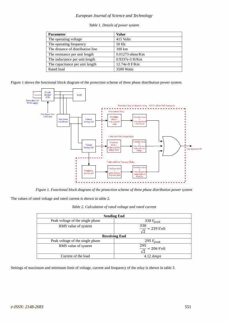
Figure 1 shows the functional block diagram of the protection scheme of three phase distribution power system.
Figure 1. Functional block diagram of the protection scheme of three phase distribution power system
The values of rated voltage and rated current is shown in table 2.
Table 2. Calculation of rated voltage and rated current
Sending End
Peak voltage of the single phase 338 𝑉𝑝𝑒𝑎𝑘
RMS value of system 338
√2= 239 𝑉𝑜𝑙𝑡
Receiving End
Peak voltage of the single phase 295 𝑉𝑝𝑒𝑎𝑘
RMS value of system 295
√2= 206 𝑉𝑜𝑙𝑡
Current of the load 4.12 𝐴𝑚𝑝𝑠
Settings of maximum and minimum limit of voltage, current and frequency of the relay is shown in table 3.
Avrupa Bilim ve Teknoloji Dergisi
e-ISSN: 2148-2683 552
Table 3. Settings of maximum and minimum limit of voltage, current and frequency of the relay
Sending End Voltage limit
Maximum Voltage 105 % of the RMS value
105
100× 239 = 250.95 𝑉𝑜𝑙𝑡𝑠
Minimum Voltage 95 % of the RMS value
95
100× 239 = 227.05 𝑉𝑜𝑙𝑡𝑠
Sending End Frequency Limit
Maximum frequency 106 % of the rated value
106
100× 50 = 53 𝐻𝑧
Minimum Frequency 92 % of the rated value
92
100× 50 = 46 𝐻𝑧
Receiving End Current Limit 5 𝐴𝑚𝑝𝑠
Timer settings 5 𝑆𝑒𝑐
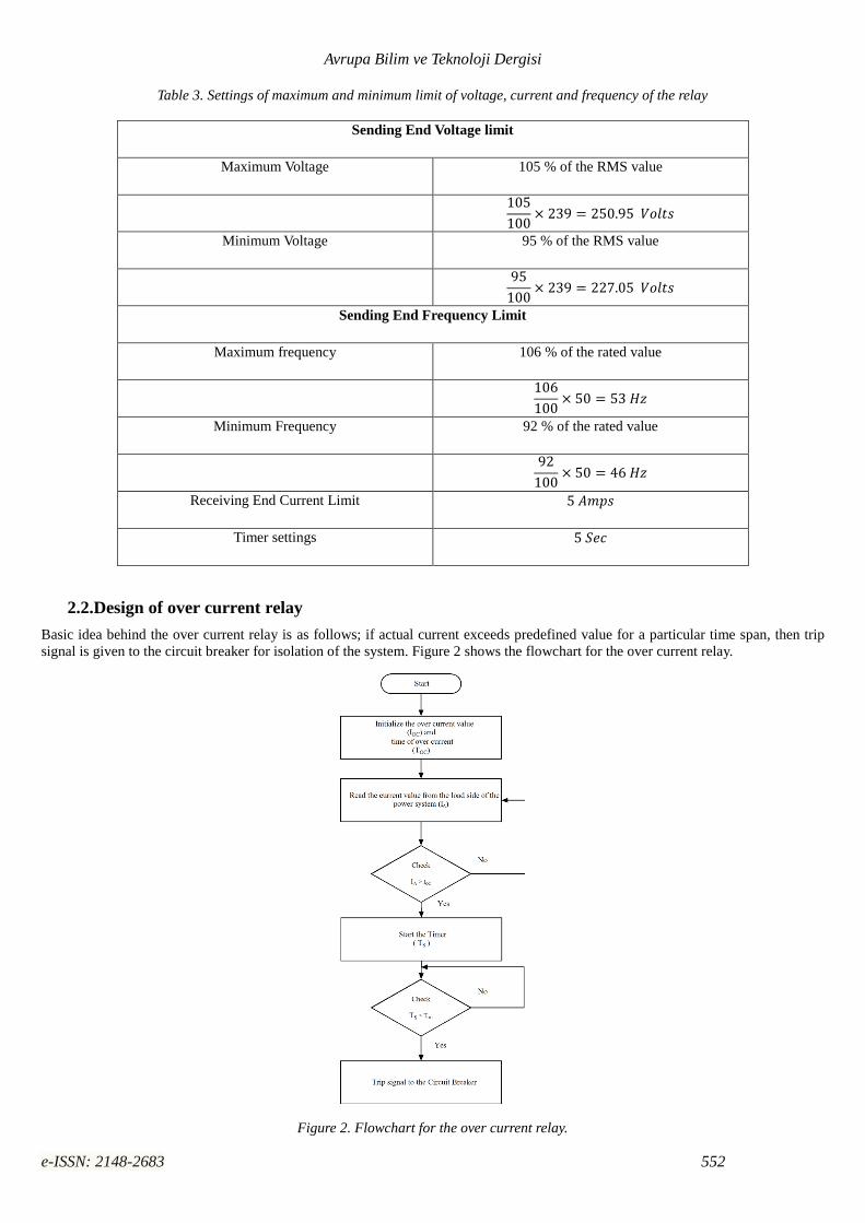
2.2.Design of over current relay
Basic idea behind the over current relay is as follows; if actual current exceeds predefined value for a particular time span, then trip
signal is given to the circuit breaker for isolation of the system. Figure 2 shows the flowchart for the over current relay.
Figure 2. Flowchart for the over current relay.
European Journal of Science and Technology
e-ISSN: 2148-2683 553
Algorithm:
i. Initialize the over current value (IOC = 5 Amps) and time of over current (TOC=5 sec).
ii. Read the value of actual current (IA) from load side of the distributed power system.
iii. Check the current limit: If IA > IOC go to next step otherwise go to previous step.
iv. Start the timer (TS) or counter for counting the seconds.
v. Check the Time limit: If TS>TOC go to next step otherwise continue counting the seconds.
vi. Send the trip signal to the circuit breaker for isolation of the power system.
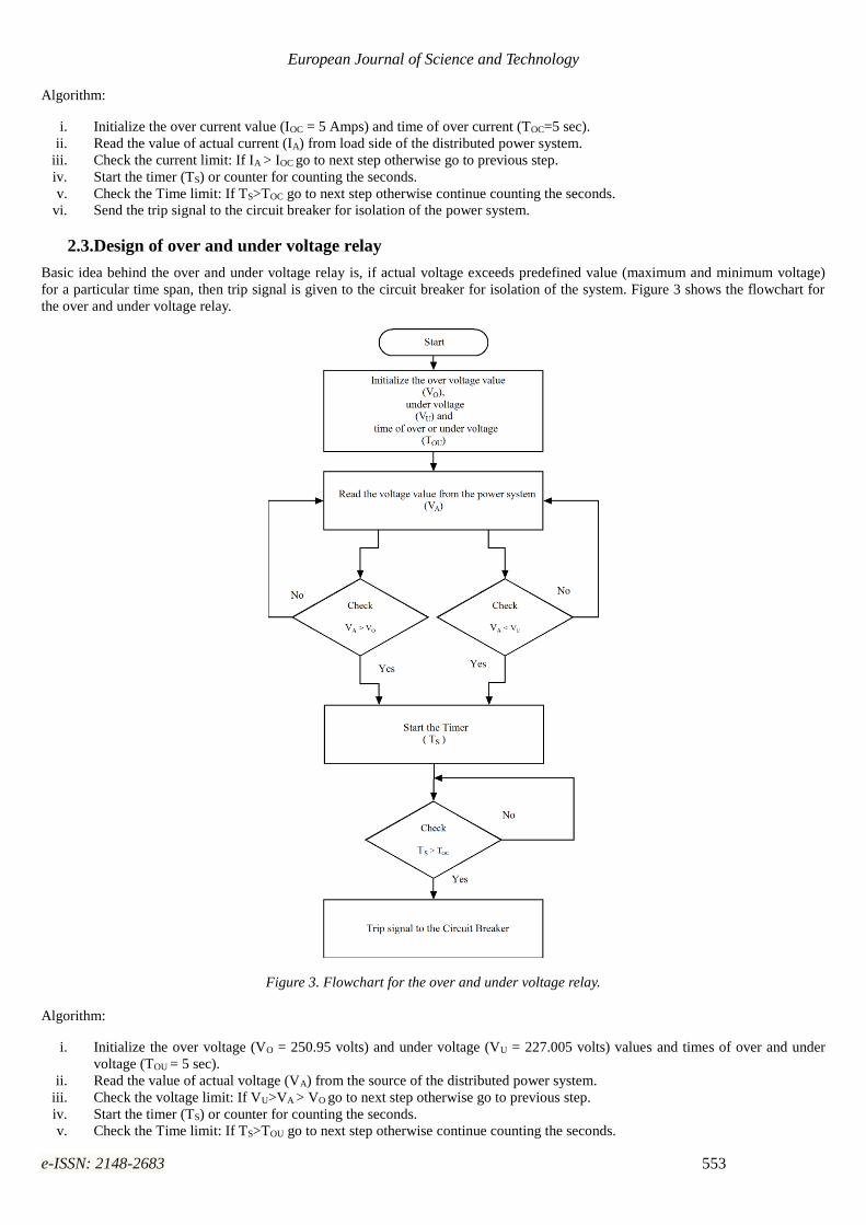
2.3.Design of over and under voltage relay
Basic idea behind the over and under voltage relay is, if actual voltage exceeds predefined value (maximum and minimum voltage)
for a particular time span, then trip signal is given to the circuit breaker for isolation of the system. Figure 3 shows the flowchart for
the over and under voltage relay.
Figure 3. Flowchart for the over and under voltage relay.
Algorithm:
i. Initialize the over voltage (VO = 250.95 volts) and under voltage (VU = 227.005 volts) values and times of over and under
voltage (TOU = 5 sec).
ii. Read the value of actual voltage (VA) from the source of the distributed power system.
iii. Check the voltage limit: If VU>VA > VO go to next step otherwise go to previous step.
iv. Start the timer (TS) or counter for counting the seconds.
v. Check the Time limit: If TS>TOU go to next step otherwise continue counting the seconds.
Avrupa Bilim ve Teknoloji Dergisi
e-ISSN: 2148-2683 554
vi. Send the trip signal to the circuit breaker for isolation of the power system.
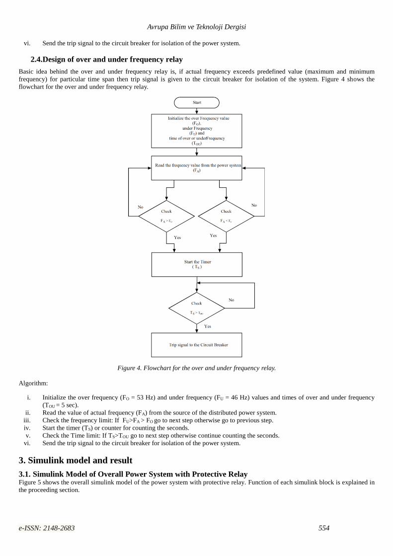
2.4.Design of over and under frequency relay
Basic idea behind the over and under frequency relay is, if actual frequency exceeds predefined value (maximum and minimum
frequency) for particular time span then trip signal is given to the circuit breaker for isolation of the system. Figure 4 shows the
flowchart for the over and under frequency relay.
Figure 4. Flowchart for the over and under frequency relay.
Algorithm:
i. Initialize the over frequency (FO = 53 Hz) and under frequency (FU = 46 Hz) values and times of over and under frequency
(TOU = 5 sec).
ii. Read the value of actual frequency (FA) from the source of the distributed power system.
iii. Check the frequency limit: If FU>FA > FO go to next step otherwise go to previous step.
iv. Start the timer (TS) or counter for counting the seconds.
v. Check the Time limit: If TS>TOU go to next step otherwise continue counting the seconds.
vi. Send the trip signal to the circuit breaker for isolation of the power system.
3. Simulink model and result
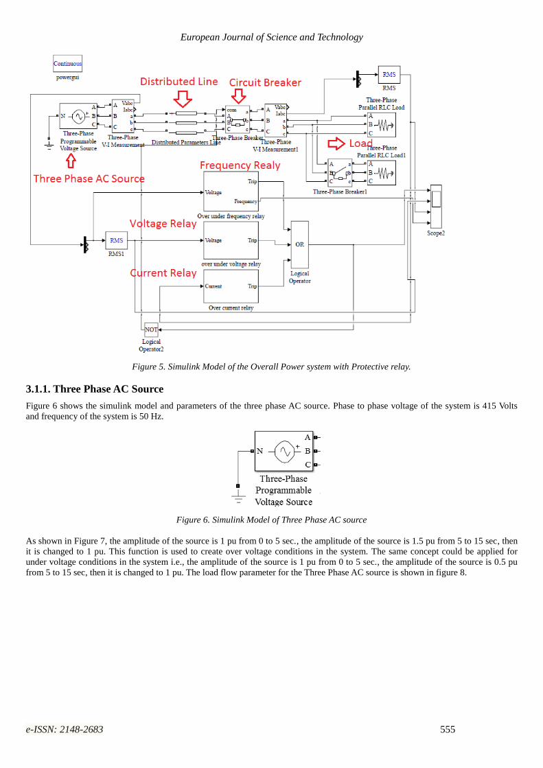
3.1. Simulink Model of Overall Power System with Protective Relay Figure 5 shows the overall simulink model of the power system with protective relay. Function of each simulink block is explained in
the proceeding section.
European Journal of Science and Technology
e-ISSN: 2148-2683 555
Figure 5. Simulink Model of the Overall Power system with Protective relay.
3.1.1. Three Phase AC Source
Figure 6 shows the simulink model and parameters of the three phase AC source. Phase to phase voltage of the system is 415 Volts
and frequency of the system is 50 Hz.
Figure 6. Simulink Model of Three Phase AC source
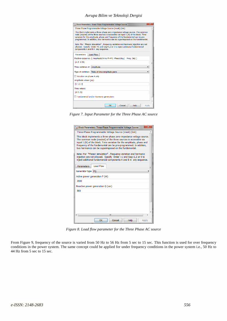
As shown in Figure 7, the amplitude of the source is 1 pu from 0 to 5 sec., the amplitude of the source is 1.5 pu from 5 to 15 sec, then
it is changed to 1 pu. This function is used to create over voltage conditions in the system. The same concept could be applied for
under voltage conditions in the system i.e., the amplitude of the source is 1 pu from 0 to 5 sec., the amplitude of the source is 0.5 pu
from 5 to 15 sec, then it is changed to 1 pu. The load flow parameter for the Three Phase AC source is shown in figure 8.
Avrupa Bilim ve Teknoloji Dergisi
e-ISSN: 2148-2683 556
Figure 7. Input Parameter for the Three Phase AC source
Figure 8. Load flow parameter for the Three Phase AC source
From Figure 9, frequency of the source is varied from 50 Hz to 56 Hz from 5 sec to 15 sec. This function is used for over frequency
conditions in the power system. The same concept could be applied for under frequency conditions in the power system i.e., 50 Hz to
44 Hz from 5 sec to 15 sec.

European Journal of Science and Technology
e-ISSN: 2148-2683 557
Figure 9 Load flow parameter for the Three Phase AC source
3.1.2. Three Distributed line Parameter
Figure 10 shows the simulink model and parameters of the distributed line. Number of phases is equal to three, frequency of the
distributed line is 50 Hz, resistance per unit length is 0.01273 ohms/Km, inductance per unit length is 0.9337 x 10 -3 H/Km,
capacitance per unit length is 12.74 x 10⁻⁹ F/Km and length of the line is 100 Km. The Input Parameter for the Distributed Line is
shown in figure 11.
Figure 10 Simulink Model of Distributed Line
Figure 11 Input Parameter for the Distributed Line
Avrupa Bilim ve Teknoloji Dergisi
e-ISSN: 2148-2683 558
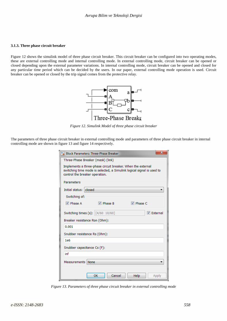
3.1.3. Three phase circuit breaker
Figure 12 shows the simulink model of three phase circuit breaker. This circuit breaker can be configured into two operating modes,
these are external controlling mode and internal controlling mode. In external controlling mode, circuit breaker can be opened or
closed depending upon the external parameter variations. In internal controlling mode, circuit breaker can be opened and closed for
any particular time period which can be decided by the users. In our paper, external controlling mode operation is used. Circuit
breaker can be opened or closed by the trip signal comes from the protective relay.
Figure 12. Simulink Model of three phase circuit breaker
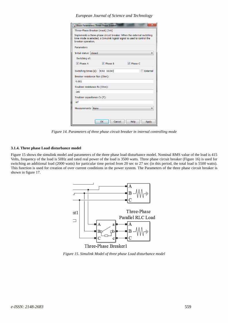
The parameters of three phase circuit breaker in external controlling mode and parameters of three phase circuit breaker in internal
controlling mode are shown in figure 13 and figure 14 respectively.
Figure 13. Parameters of three phase circuit breaker in external controlling mode
European Journal of Science and Technology
e-ISSN: 2148-2683 559
Figure 14. Parameters of three phase circuit breaker in internal controlling mode
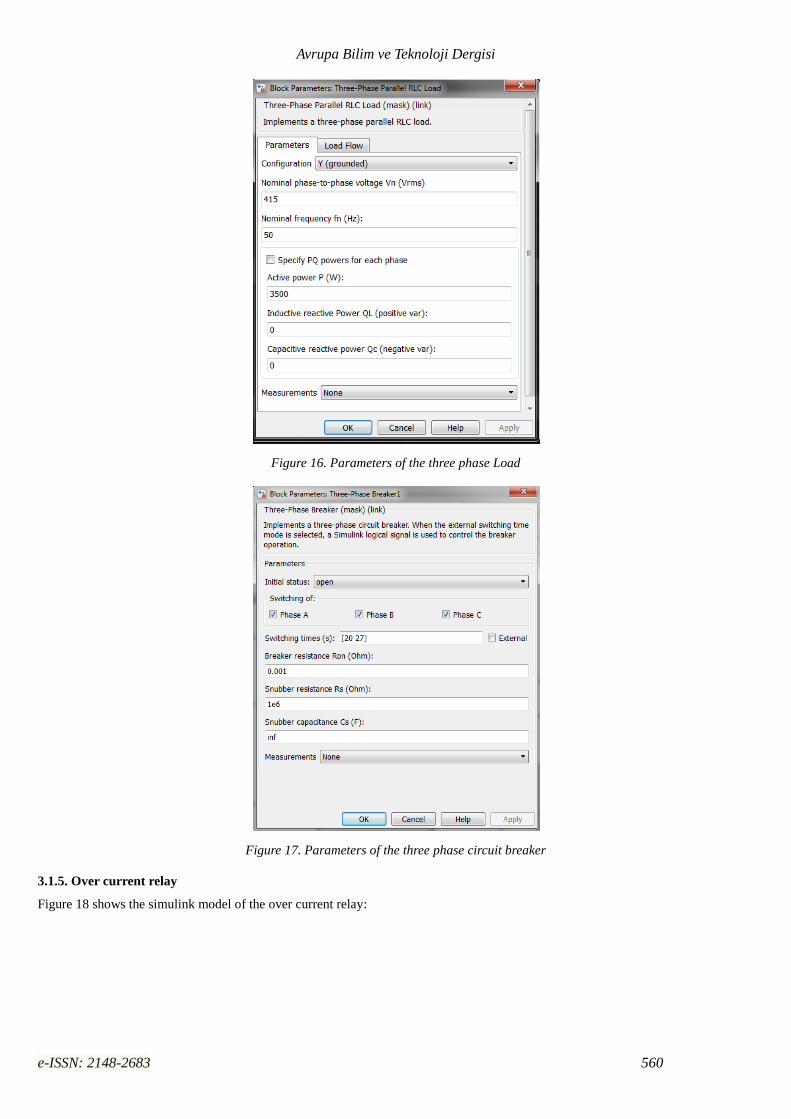
3.1.4. Three phase Load disturbance model
Figure 15 shows the simulink model and parameters of the three phase load disturbance model. Nominal RMS value of the load is 415
Volts, frequency of the load is 50Hz and rated real power of the load is 3500 watts. Three phase circuit breaker (Figure 16) is used for
switching an additional load (2000 watts) for particular time period from 20 sec to 27 sec (in this period, the total load is 5500 watts).
This function is used for creation of over current conditions in the power system. The Parameters of the three phase circuit breaker is
shown in figure 17.
Figure 15. Simulink Model of three phase Load disturbance model
Avrupa Bilim ve Teknoloji Dergisi
e-ISSN: 2148-2683 560
Figure 16. Parameters of the three phase Load
Figure 17. Parameters of the three phase circuit breaker
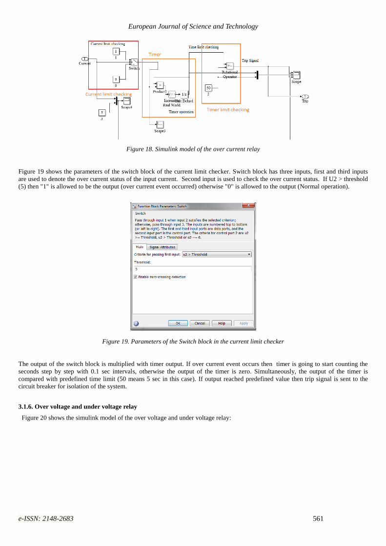
3.1.5. Over current relay
Figure 18 shows the simulink model of the over current relay:
European Journal of Science and Technology
e-ISSN: 2148-2683 561
Figure 18. Simulink model of the over current relay
Figure 19 shows the parameters of the switch block of the current limit checker. Switch block has three inputs, first and third inputs
are used to denote the over current status of the input current. Second input is used to check the over current status. If U2 > threshold
(5) then "1" is allowed to be the output (over current event occurred) otherwise "0" is allowed to the output (Normal operation).
Figure 19. Parameters of the Switch block in the current limit checker
The output of the switch block is multiplied with timer output. If over current event occurs then timer is going to start counting the
seconds step by step with 0.1 sec intervals, otherwise the output of the timer is zero. Simultaneously, the output of the timer is
compared with predefined time limit (50 means 5 sec in this case). If output reached predefined value then trip signal is sent to the
circuit breaker for isolation of the system.
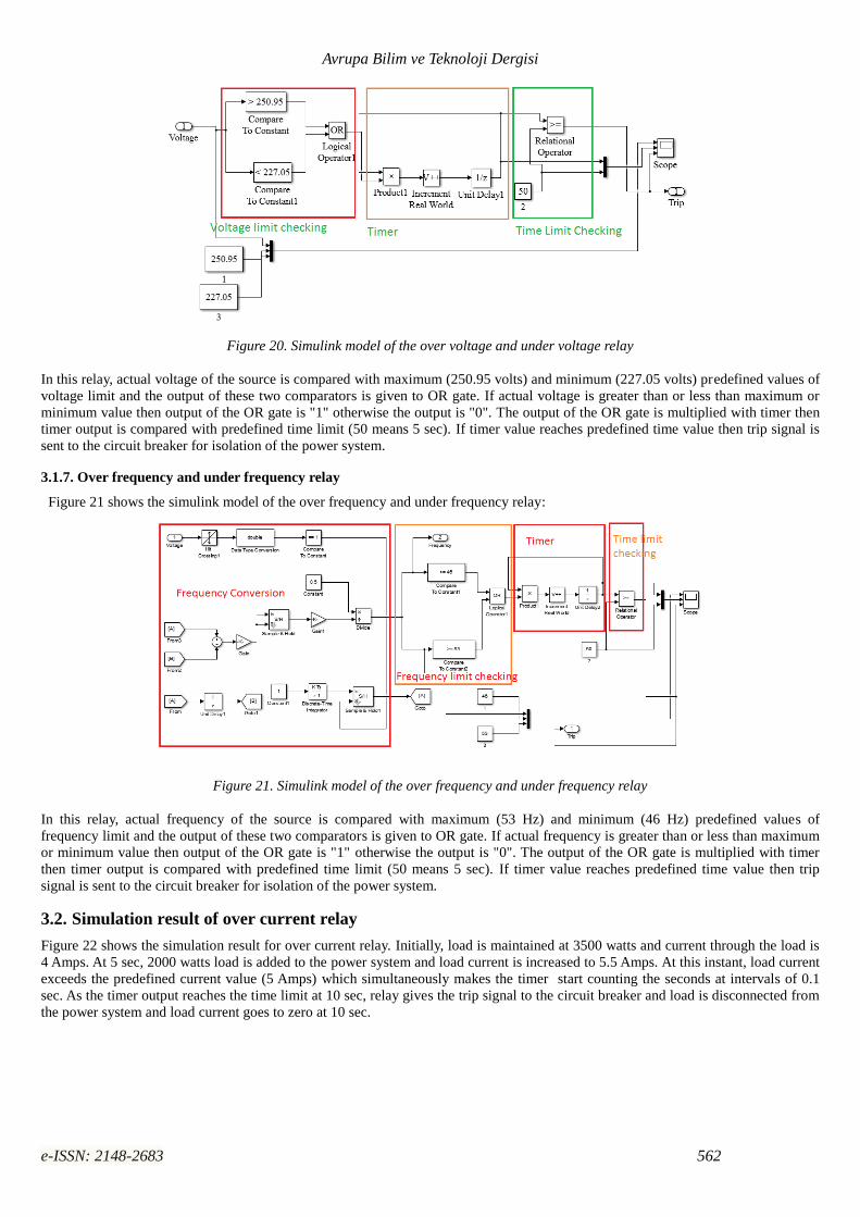
3.1.6. Over voltage and under voltage relay
Figure 20 shows the simulink model of the over voltage and under voltage relay:
Avrupa Bilim ve Teknoloji Dergisi
e-ISSN: 2148-2683 562
Figure 20. Simulink model of the over voltage and under voltage relay
In this relay, actual voltage of the source is compared with maximum (250.95 volts) and minimum (227.05 volts) predefined values of
voltage limit and the output of these two comparators is given to OR gate. If actual voltage is greater than or less than maximum or
minimum value then output of the OR gate is "1" otherwise the output is "0". The output of the OR gate is multiplied with timer then
timer output is compared with predefined time limit (50 means 5 sec). If timer value reaches predefined time value then trip signal is
sent to the circuit breaker for isolation of the power system.
3.1.7. Over frequency and under frequency relay
Figure 21 shows the simulink model of the over frequency and under frequency relay:
Figure 21. Simulink model of the over frequency and under frequency relay
In this relay, actual frequency of the source is compared with maximum (53 Hz) and minimum (46 Hz) predefined values of
frequency limit and the output of these two comparators is given to OR gate. If actual frequency is greater than or less than maximum
or minimum value then output of the OR gate is "1" otherwise the output is "0". The output of the OR gate is multiplied with timer
then timer output is compared with predefined time limit (50 means 5 sec). If timer value reaches predefined time value then trip
signal is sent to the circuit breaker for isolation of the power system.
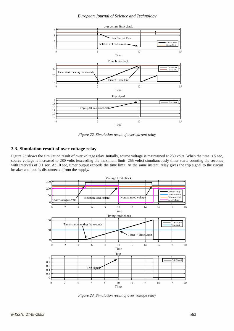
3.2. Simulation result of over current relay
Figure 22 shows the simulation result for over current relay. Initially, load is maintained at 3500 watts and current through the load is
4 Amps. At 5 sec, 2000 watts load is added to the power system and load current is increased to 5.5 Amps. At this instant, load current
exceeds the predefined current value (5 Amps) which simultaneously makes the timer start counting the seconds at intervals of 0.1
sec. As the timer output reaches the time limit at 10 sec, relay gives the trip signal to the circuit breaker and load is disconnected from
the power system and load current goes to zero at 10 sec.
European Journal of Science and Technology
e-ISSN: 2148-2683 563
Figure 22. Simulation result of over current relay
3.3. Simulation result of over voltage relay
Figure 23 shows the simulation result of over voltage relay. Initially, source voltage is maintained at 239 volts. When the time is 5 sec,
source voltage is increased to 280 volts (exceeding the maximum limit- 255 volts) simultaneously timer starts counting the seconds
with intervals of 0.1 sec. At 10 sec, timer output exceeds the time limit. At the same instant, relay gives the trip signal to the circuit
breaker and load is disconnected from the supply.
Figure 23. Simulation result of over voltage relay
Avrupa Bilim ve Teknoloji Dergisi
e-ISSN: 2148-2683 564
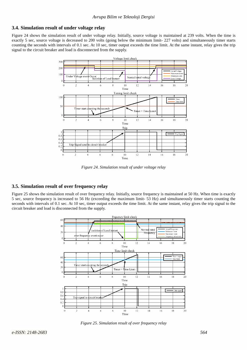
3.4. Simulation result of under voltage relay
Figure 24 shows the simulation result of under voltage relay. Initially, source voltage is maintained at 239 volts. When the time is
exactly 5 sec, source voltage is decreased to 200 volts (going below the minimum limit- 227 volts) and simultaneously timer starts
counting the seconds with intervals of 0.1 sec. At 10 sec, timer output exceeds the time limit. At the same instant, relay gives the trip
signal to the circuit breaker and load is disconnected from the supply.
Figure 24. Simulation result of under voltage relay
3.5. Simulation result of over frequency relay
Figure 25 shows the simulation result of over frequency relay. Initially, source frequency is maintained at 50 Hz. When time is exactly
5 sec, source frequency is increased to 56 Hz (exceeding the maximum limit- 53 Hz) and simultaneously timer starts counting the
seconds with intervals of 0.1 sec. At 10 sec, timer output exceeds the time limit. At the same instant, relay gives the trip signal to the
circuit breaker and load is disconnected from the supply.
Figure 25. Simulation result of over frequency relay
European Journal of Science and Technology
e-ISSN: 2148-2683 565
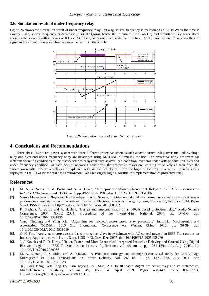
3.6. Simulation result of under frequency relay
Figure 26 shows the simulation result of under frequency relay. Initially, source frequency is maintained at 50 Hz.When the time is
exactly 5 sec, source frequency is decreased to 44 Hz (going below the minimum limit- 46 Hz) and simultaneously timer starts
counting the seconds with intervals of 0.1 sec. At 10 sec, timer output exceeds the time limit. At the same instant, relay gives the trip
signal to the circuit breaker and load is disconnected from the supply.
Figure 26. Simulation result of under frequency relay.
4. Conclusions and Recommendations
Three phase distributed power system with three different protective schemes such as over current relay, over and under voltage
relay and over and under frequency relay are developed using MATLAB / Simulink toolbox. The protective relay are tested for
different operating conditions of the distributed power system such as over load condition, over and under voltage condition, over and
under frequency condition. At each one of operating conditions, the protective relays are working effectively as seen from the
simulation results. Protective relays are explained with simple flowcharts. From the logic of the protective relay it can be easily
deployed in the FPGA kit for real time environment. We used digital logic algorithm for implementation of protective relay.
References
[1]. M. A. Al-Nema, S. M. Bashi and A. A. Ubaid, "Microprocessor-Based Overcurrent Relays," in IEEE Transactions on
Industrial Electronics, vol. IE-33, no. 1, pp. 49-51, Feb. 1986. doi: 10.1109/TIE.1986.351706.
[2]. Varun Maheshwari, Bhagwan Das Devulapalli, A.K. Saxena, FPGA-based digital overcurrent relay with concurrent sense-
process-communicate cycles, International Journal of Electrical Power & Energy Systems, Volume 55, February 2014, Pages
66-73, ISSN 0142-0615, http://dx.doi.org/10.1016/j.ijepes.2013.08.032.
[3]. K. Shehata, A. Bahaa and A. Hashad, "Design and implementation of an FPGA based protection relay," Radio Science
Conference, 2004. NRSC 2004. Proceedings of the Twenty-First National, 2004, pp. D4-1-6. doi:
10.1109/NRSC.2004.1321856
[4]. Yang Tingfang and Yang Xin, "Algorithm for microprocessor-based relay protection," Industrial Mechatronics and
Automation (ICIMA), 2010 2nd International Conference on, Wuhan, China, 2010, pp. 56-59. doi:
10.1109/ICINDMA.2010.5538099
[5]. G. H. Fox, "Applying microprocessor-based protective relays in switchgear with AC control power," in IEEE Transactions on
Industry Applications, vol. 41, no. 6, pp. 1436-1443, Nov.-Dec. 2005. doi: 10.1109/TIA.2005.858280
[6]. J. J. Novak and R. D. Kirby, "Better, Faster, and More Economical Integrated Protective Relaying and Control Using Digital
Bits and Logic," in IEEE Transactions on Industry Applications, vol. 46, no. 4, pp. 1281-1294, July-Aug. 2010. doi:
10.1109/TIA.2010.2050986
[7]. M. A. Zamani, T. S. Sidhu and A. Yazdani, "A Protection Strategy and Microprocessor-Based Relay for Low-Voltage
Microgrids," in IEEE Transactions on Power Delivery, vol. 26, no. 3, pp. 1873-1883, July 2011. doi:
10.1109/TPWRD.2011.2120628
[8]. Jong Kang Park, Jong Tae Kim, Myong-Chul Shin, A CORDIC-based digital protective relay and its architecture,
Microelectronics Reliability, Volume 49, Issue 4, April 2009, Pages 438-447, ISSN 0026-2714,
http://dx.doi.org/10.1016/j.microrel.2008.12.008.