design, manufacturing and installation of segmental lining...
TRANSCRIPT

Design, manufacturing and installation of
segmental lining in TBM tunnelsNFF – TBM Applications II, 6. - 7. June 2016
Johannes Gollegger, Technical Manager EPC TBM Follo Line Project

Typical cross sections
Follo Line Tunnel
Norway
Wienerwald Tunnel
(Austria)
Kaiser-Wilhelm Tunnel
Germany

Introduction
Ring geometry
Ring consists of 4 to 8 segments
Tunnel diameter
Max. permissible size of segments for intended transport
Mechanical mechanisms for installing segments by erector
Number of thrust jacks and their distribution over the ring
Optimization according to project specific factors
Ring conicity
Tunnel alignment – min curve radius
Water tightness

Swiss strut lining
Ring consists of 6 segments
No bolts or dowels
No gasket
Key stone always at the bottom
Especially used for project with
low requirements to segmental
lining (double shell lining)

Hexagonal ring (Honeycomb)
Ring consists of 4 segments
Especially used for hydropower
projects (i.e. headrace tunnel)
The joints are not planar, but
convex/concave
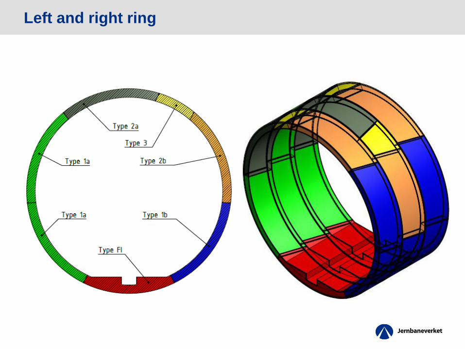
Left and right ring

Universal ring

Ring conicity
K = conicity
bm = mean ring width
R = tunnel radius
Da = outer diameter
Parallel segment Honeycomb
segmentAsymmetric tapered
segment
Symmetric tapered
segment

Joint design – groove and tongue systems

Gaskets – glued and anchored

Gaskets – performance
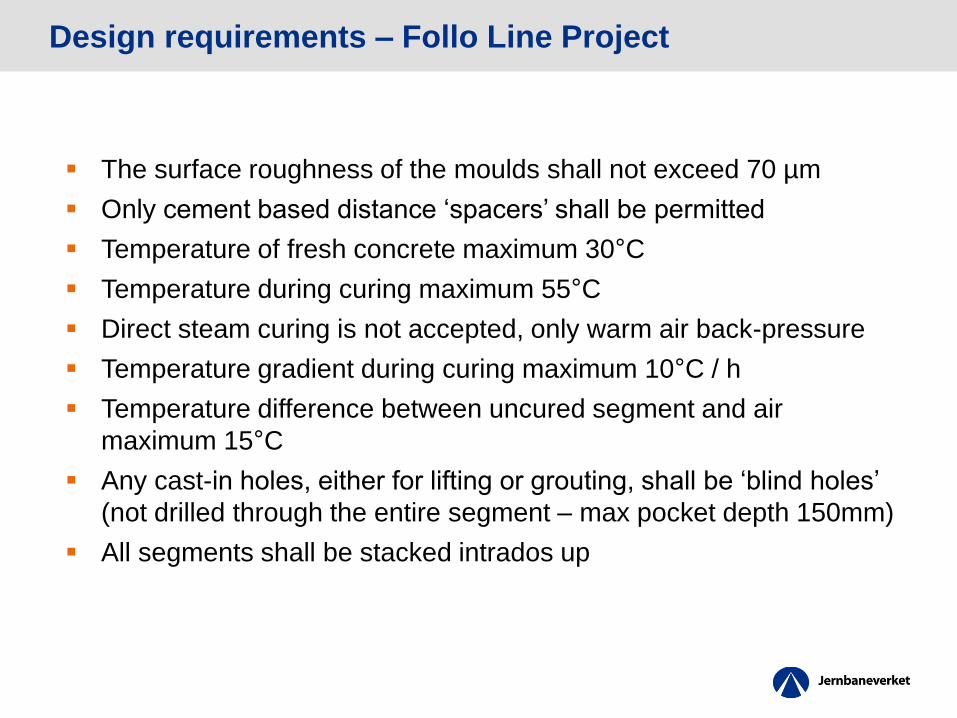
Design requirements – Follo Line Project
The surface roughness of the moulds shall not exceed 70 µm
Only cement based distance ‘spacers’ shall be permitted
Temperature of fresh concrete maximum 30°C
Temperature during curing maximum 55°C
Direct steam curing is not accepted, only warm air back-pressure
Temperature gradient during curing maximum 10°C / h
Temperature difference between uncured segment and air
maximum 15°C
Any cast-in holes, either for lifting or grouting, shall be ‘blind holes’
(not drilled through the entire segment – max pocket depth 150mm)
All segments shall be stacked intrados up

Design requirements – Follo Line Project
A combination of steel bars, wire mesh and steel fibres maybe
used. However, the minimum reinforcement requirement shall be
provided by steel bars
For fire protection PP-fibres shall be added
The maximum allowed concrete grade is B55
The use of suitable excavated muck for segment production to be
maximised
Trial assembly to be performed

Tolerances
Circumferential lengths +/- 0.6 mm
Segment thickness + 3 mm / - 1.5 mm
Width +/- 0.5 mm
Joint plane of circumferential joint +/- 0.5 mm
Joint plane of radial joint face +/- 0.5 mm
Depth of gasket sealing grooves + 0.2 mm / -0.0 mm
Width of gasket sealing groove max deviation + 0.2 mm / -0.0 mm
Distance from inner edge of segment to gasket sealing groove max
deviation +/- 1 mm
Rotation of radial joint face across element centre plain parallel to
inner face +/- 0.3 mm
Rotation of radial joint face across element centre plain
perpendicular to inner face +/- 0.5 mm
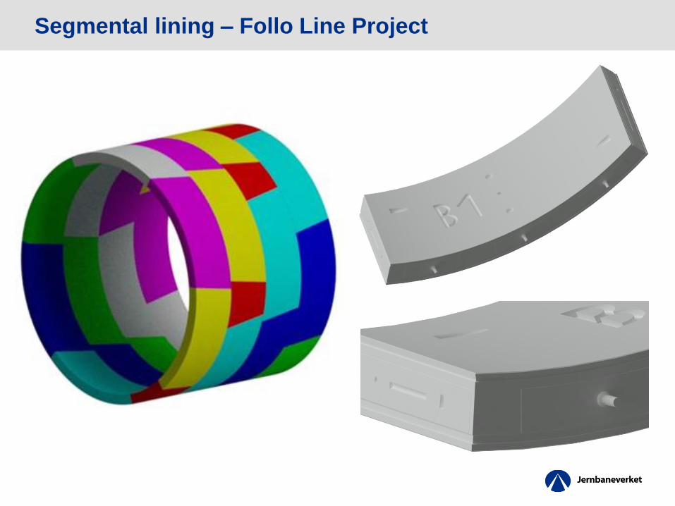
Segmental lining – Follo Line Project
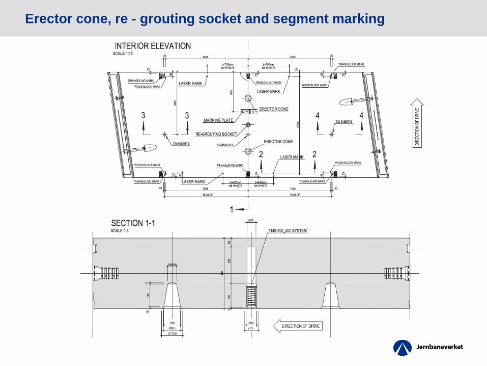
Erector cone, re - grouting socket and segment marking

Standard bolt and biblock connector

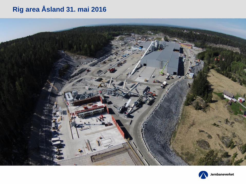
Rig area Åsland 31. mai 2016
1. Tunnelportal
2. Transportbånd
3. Massehåndtering
4. Knuseverk
5. Betongfabrikk
6. Elementfabrikk
7. Lagerområde for elementer
8. Kontorrigg
9. Boligrigg
Rig area Åsland 31. mai 2016
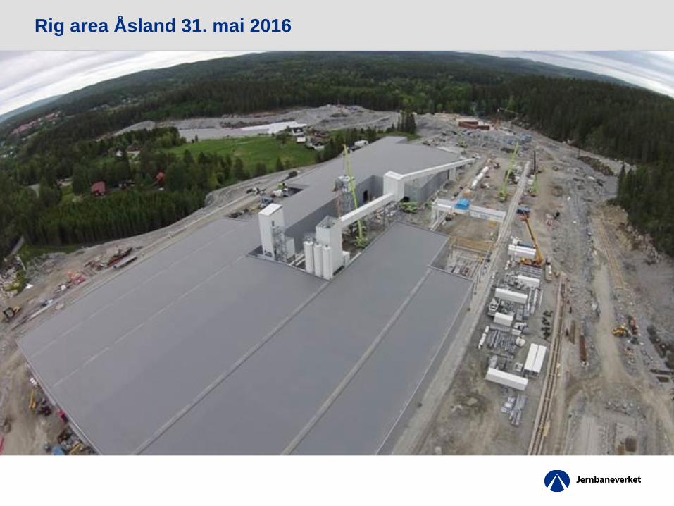
Rig area Åsland 31. mai 2016
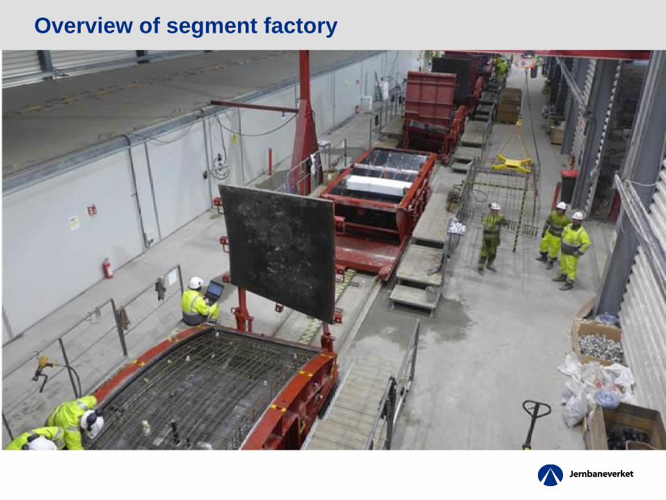
Overview of segment factory
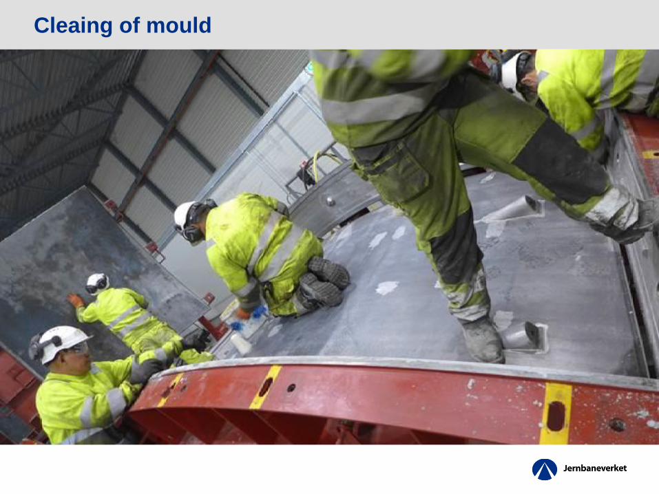
Cleaing of mould

Installation of inserts

Finalisation

Concreting

Mould on the way the curing chamber
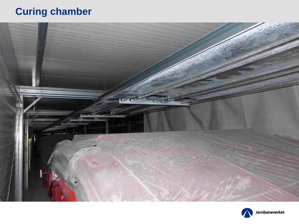
Curing chamber

Moulds leaving the curing chamber

Rotation of segment
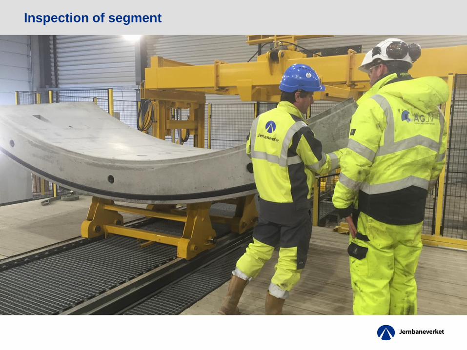
Inspection of segment
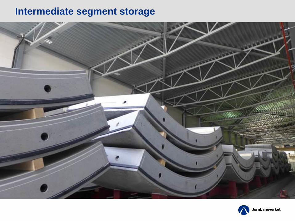
Intermediate segment storage
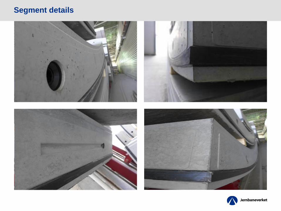
Segment details


Installation of segmental ring

Installation of segmental ring
RING COMBINATIONS POSSIBLE - RING POSITION
1 2 3 4 5 6 7 8 9 10 11 12 13 14 15 16 17 18 19
RIN
G C
OM
BIN
AT
ION
S P
OSS
IBLE
-R
ING
PO
SITI
ON
1
2
3
4
5
6
7
8
9
10
11
12
13
14
15
16
17
18
19

Segment repair
Thank you very much for your attention!