design intermittent sand filter
TRANSCRIPT
Recommended Standards and Guidance for Performance, Application, Design, and Operation & Maintenance
Intermittent Sand Filter Systems
July 2012
Recommended Standards and Guidance for Performance, Application, Design, and Operation & Maintenance
Intermittent Sand Filter Systems July 2012
For information or additional copies of this report contact: Wastewater Management Program Physical address: 243 Israel Road SE, Tumwater, WA 98501 Mailing address: PO Box 47824, Olympia, WA 98504-7824 Phone: (360) 236-3330 FAX: (360) 236-2257 Email: [email protected] Mary Selecky Secretary of Health For persons with disabilities, this document is available upon request in other formats. To submit a request, please call 1-888-586-9427 (TDD/TTY 1-800-833-6388). Para personas discapacitadas, este documento está disponible a su pedido en otros formatos. Para hacer su pedido llame al 1-888-586-9427 (TDD/TTY 1-800-833-6388). DOH Publication #337-007
Intermittent Sand Filter Systems -- Recommended Standards and Guidance Effective Date: July 1, 2012
DOH 337-007 Page 3 of 32
Contents Page
Preface .............................................................................................................................................5
Introduction ....................................................................................................................................7
1. Performance Standards..........................................................................................................8
2. Application Standards ............................................................................................................8
2.1. Listing ..........................................................................................................................8 2.2. Permitting .....................................................................................................................8 2.3. Influent Characteristics ..............................................................................................10 2.4. Pretreatment ...............................................................................................................10 2.5. Location Requirements ..............................................................................................11 2.6. Installation Issues .......................................................................................................11 2.7. Soil Dispersal Component .........................................................................................11
3. Design Standards ..................................................................................................................12
3.1. Design Approval ........................................................................................................12 3.2. Filter Bed ...................................................................................................................12 3.3. Wastewater Distribution ............................................................................................14 3.4. Minimum Dosing Frequency: ....................................................................................14 3.5. Treated Wastewater (Filtrate) Collection and Discharge ..........................................15
4. Operation, Monitoring, and Maintenance .........................................................................15
4.1. Management ...............................................................................................................15 4.2. User’s Manual ............................................................................................................15 4.3. Monitoring and Maintenance .....................................................................................16 4.4. Action Conditions ......................................................................................................18
Appendix A – Filter Media Specifications .................................................................................19
Appendix B - Containment Vessel Standards ...........................................................................21
Appendix C - Underdrains ..........................................................................................................27
Appendix D - Inspection/Monitor Ports ....................................................................................29
Appendix E - Disposal of Contaminated Filter Media .............................................................30
Appendix F - Bibliography ..........................................................................................................31
Intermittent Sand Filter Systems -- Recommended Standards and Guidance Effective Date: July 1, 2012
DOH 337-007 Page 4 of 32
Figures:
Figure 1 - Typical Layout of an Intermittent Sand Filter ........................................................ 8 Figure 2 - Typical Intermittent Sand Filter, Cross Section...................................................... 9 Figure 3 - Typical Intermittent Sand Filter, Top View ............................................................ 9 Figure 4. Typical Cross-section of an Intermittent Sand Filter Underdrain ......................... 27 Figure 5. Typical Cross-section of a Pumpwell ................................................................... 28
Glossary of Terms ................ http://www.doh.wa.gov/Portals/1/Documents/Pubs/337-028.pdf

Intermittent Sand Filter Systems -- Recommended Standards and Guidance Effective Date: July 1, 2012
DOH 337-007 Page 5 of 32
Preface The recommended standards contained in this document have been developed for statewide application. Regional differences may, however, result in application of this technology in a manner different than it is presented here. In some localities, greater allowances than those described here may reasonably be granted. In other localities, allowances that are provided for in this document may be restricted. In either setting, the local health officer has full authority in the application of this technology, consistent with Chapter 246-272A WAC and local jurisdictional rules. If any provision of these recommended standards is inconsistent with local jurisdictional rules, regulations, ordinances, policies, procedures, or practices, the local standards take precedence. Application of the recommended standards presented here is at the full discretion of the local health officer. Local jurisdictional application of these recommended standards may be: 1) Adopted as part of local rules, regulations or ordinances - When the recommended
standards, either as they are written or modified to more accurately reflect local conditions, are adopted as part of the local rules, their application is governed by local rule authority.
2) Referred to as technical guidance in the application of the technology - The
recommended standards, either as they are written or modified to more accurately reflect local conditions, may be used locally as technical guidance.
Application of these recommended standards may occur in a manner that combines these two approaches. How these recommended standards are applied at the local jurisdictional level remains at the discretion of the local health officer and the local board of health. The recommended standards presented here are provided in typical rule language to assist those local jurisdictions where adoption in local rules is the preferred option. Other information and guidance is presented in text boxes with a modified font style to easily distinguish it from the recommended standards. Glossary of Terms: A glossary of common terms for all RS&Gs can be found on the DOH Web site at http://www.doh.wa.gov/Portals/1/Documents/Pubs/337-028.pdf. The recommended standards contained in this document have been primarily written to support the design of on-site sewage systems with design flows less than 3500 gpd, but may also be applied to large on-site sewage systems (LOSS). With the adoption of the revised LOSS rule, chapter 246-272B WAC, in 2011, some provisions of the RS&Gs may not be appropriate or allowed for LOSS. Many applicable requirements from the RS&Gs have already been included in the LOSS rule. Design engineers and others interested in LOSS are directed to consult the rule and LOSS program staff before or instead of the RS&Gs.
Intermittent Sand Filter Systems -- Recommended Standards and Guidance Effective Date: July 1, 2012
DOH 337-007 Page 6 of 32
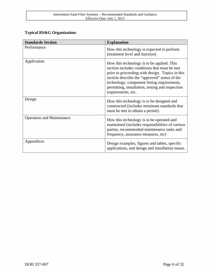
Typical RS&G Organization: Standards Section Explanation Performance How this technology is expected to perform
(treatment level and function)
Application How this technology is to be applied. This section includes conditions that must be met prior to proceeding with design. Topics in this section describe the “approved” status of the technology, component listing requirements, permitting, installation, testing and inspection requirements, etc.
Design How this technology is to be designed and constructed (includes minimum standards that must be met to obtain a permit).
Operation and Maintenance How this technology is to be operated and maintained (includes responsibilities of various parties, recommended maintenance tasks and frequency, assurance measures, etc)
Appendices Design examples, figures and tables, specific applications, and design and installation issues.
Intermittent Sand Filter Systems -- Recommended Standards and Guidance Effective Date: July 1, 2012
DOH 337-007 Page 7 of 32
Introduction Intermittent sand filters provide biodegradation or decomposition of wastewater constituents by bringing the wastewater into close contact with a well developed aerobic biological community attached to the surfaces of the filter media. This process requires unsaturated downward flow of the effluent through the filter media. The filter media may be mineral sand or equivalently sized crushed glass meeting one of the media specifications listed in Appendix A. The media is contained in a watertight vessel either below the surface of the ground or wholly or partially elevated in a containment vessel. Proper function requires that influent to the filter be distributed over the media in controlled, uniform doses. In order to achieve accurate dosing, these systems require timed dosing with associated pump chambers, electrical components, and distribution network, with a minimum of 4 to 18 doses per day (depending on the sand media) spread evenly over a 24 hour period. The effluent is collected in the bottom of the filter and discharged either by gravity or pressure to a soil dispersal component, usually a conventional sub-surface drainfield. This technology is used on sites with shallow soil conditions where treatment must be accomplished before the effluent is discharged into the soil. Sand filter effluent may be discharged to a soil profile containing as little as 12 inches of vertical separation. Intermittent sand filters are also used as part of a mitigation strategy when horizontal separations are reduced.
Intermittent Sand Filter Systems -- Recommended Standards and Guidance Effective Date: July 1, 2012
DOH 337-007 Page 8 of 32
1. Performance Standards
1.1.1 Based on sand column studies and field testing, intermittent sand filters, when constructed and used according to these standards and guidance, is expected to perform to Treatment Level B.
1.1.2 Effluent from an intermittent sand filter can be discharged to vertical
separations of at least 12 inches in soil type 2 through 6 and at least 18 inches in soil type 1
2. Application Standards
2.1. Listing While they are a public domain treatment technology, intermittent sand filters are included in the Department of Health’s List of Registered On-site Treatment and Distribution Products (Registered List) as a category 1 treatment technology (designed to treat typical residential sewage).
2.2. Permitting
Installation and, if required, operational permits must be obtained from the appropriate local health officer prior to installation and use.
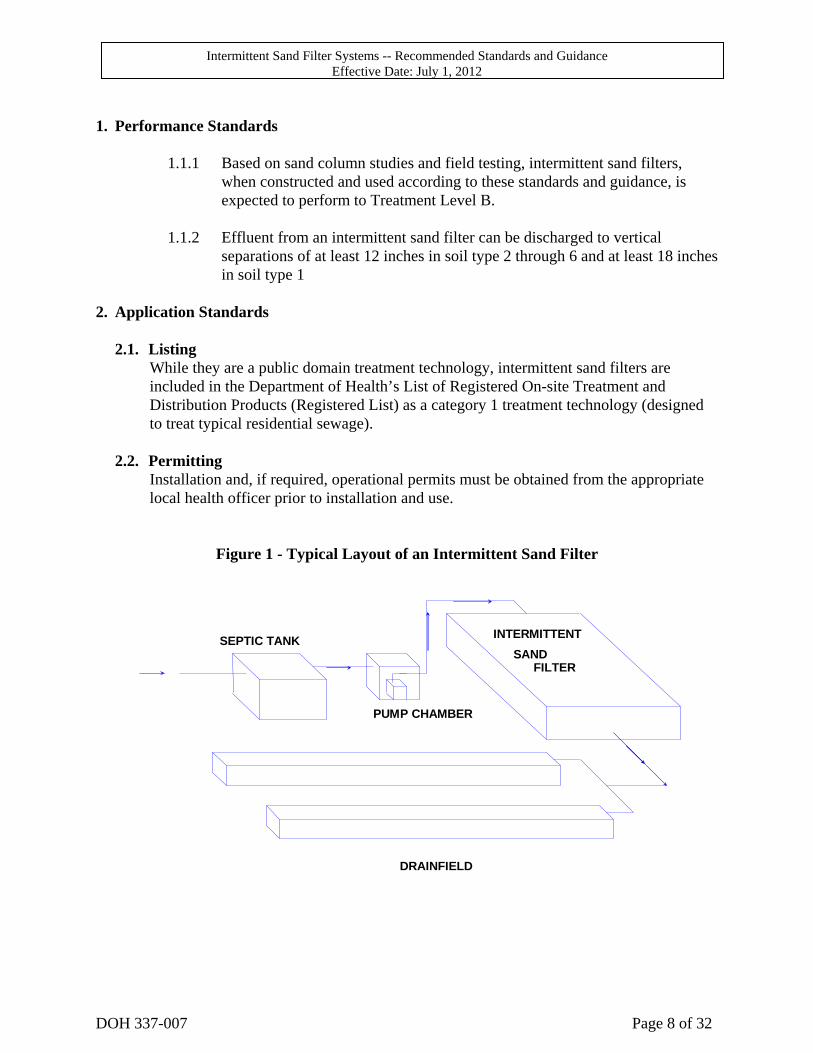
Figure 1 - Typical Layout of an Intermittent Sand Filter
SEPTIC TANK
PUMP CHAMBER
SANDFILTER
DRAINFIELD
INTERMITTENT
Intermittent Sand Filter Systems -- Recommended Standards and Guidance Effective Date: July 1, 2012
DOH 337-007 Page 9 of 32
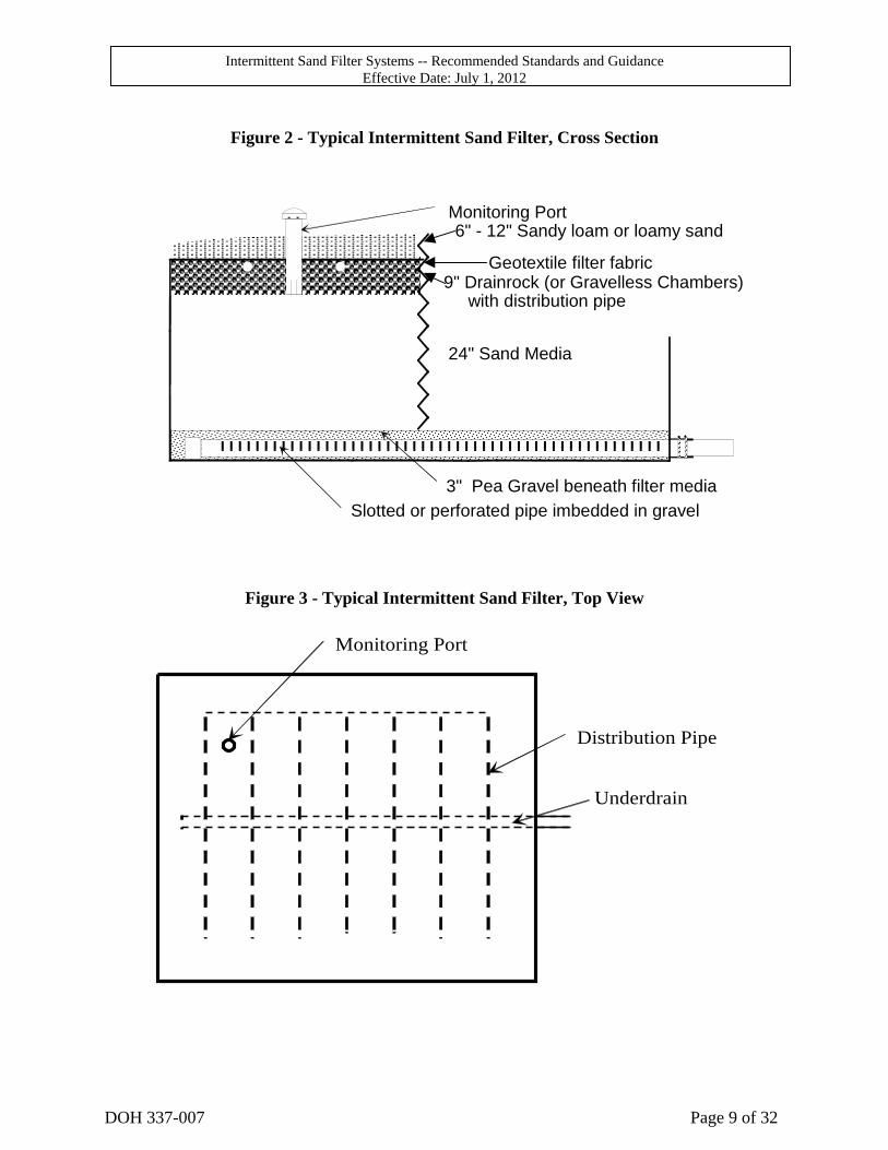
Figure 2 - Typical Intermittent Sand Filter, Cross Section
3" Pea Gravel beneath filter media
Geotextile filter fabric
24" Sand Media
Monitoring Port6" - 12" Sandy loam or loamy sand
Slotted or perforated pipe imbedded in gravel
9" Drainrock (or Gravelless Chambers) with distribution pipe
Figure 3 - Typical Intermittent Sand Filter, Top View
Monitoring Port
Distribution Pipe
Underdrain
Intermittent Sand Filter Systems -- Recommended Standards and Guidance Effective Date: July 1, 2012
DOH 337-007 Page 10 of 32
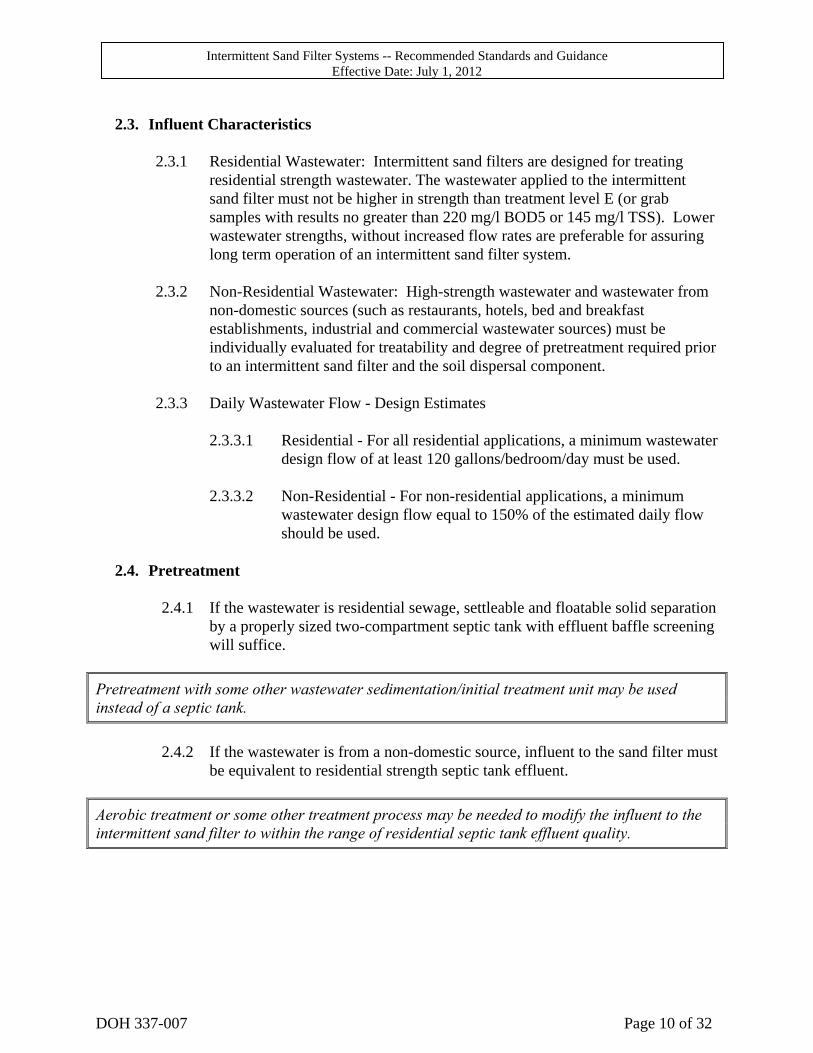
2.3. Influent Characteristics
2.3.1 Residential Wastewater: Intermittent sand filters are designed for treating
residential strength wastewater. The wastewater applied to the intermittent sand filter must not be higher in strength than treatment level E (or grab samples with results no greater than 220 mg/l BOD5 or 145 mg/l TSS). Lower wastewater strengths, without increased flow rates are preferable for assuring long term operation of an intermittent sand filter system.
2.3.2 Non-Residential Wastewater: High-strength wastewater and wastewater from
non-domestic sources (such as restaurants, hotels, bed and breakfast establishments, industrial and commercial wastewater sources) must be individually evaluated for treatability and degree of pretreatment required prior to an intermittent sand filter and the soil dispersal component.
2.3.3 Daily Wastewater Flow - Design Estimates
2.3.3.1 Residential - For all residential applications, a minimum wastewater
design flow of at least 120 gallons/bedroom/day must be used. 2.3.3.2 Non-Residential - For non-residential applications, a minimum
wastewater design flow equal to 150% of the estimated daily flow should be used.
2.4. Pretreatment
2.4.1 If the wastewater is residential sewage, settleable and floatable solid separation
by a properly sized two-compartment septic tank with effluent baffle screening will suffice.
Pretreatment with some other wastewater sedimentation/initial treatment unit may be used instead of a septic tank.
2.4.2 If the wastewater is from a non-domestic source, influent to the sand filter must
be equivalent to residential strength septic tank effluent.
Aerobic treatment or some other treatment process may be needed to modify the influent to the intermittent sand filter to within the range of residential septic tank effluent quality.
Intermittent Sand Filter Systems -- Recommended Standards and Guidance Effective Date: July 1, 2012
DOH 337-007 Page 11 of 32
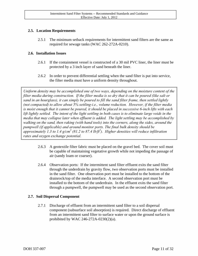
2.5. Location Requirements
2.5.1 The minimum setback requirements for intermittent sand filters are the same as
required for sewage tanks (WAC 262-272A-0210).
2.6. Installation Issues
2.6.1 If the containment vessel is constructed of a 30 mil PVC liner, the liner must be protected by a 3 inch layer of sand beneath the liner.
2.6.2 In order to prevent differential settling when the sand filter is put into service,
the filter media must have a uniform density throughout.
Uniform density may be accomplished one of two ways, depending on the moisture content of the filter media during construction. If the filter media is so dry that it can be poured (like salt or sand in an hourglass), it can simply be poured to fill the sand filter frame, then settled lightly (not compacted) to allow about 5% settling-i.e., volume reduction. However, if the filter media is moist enough that it cannot be poured, it should be placed in successive 6-inch lifts with each lift lightly settled. The intent of the light settling in both cases is to eliminate large voids in the media that may collapse later when effluent is added. The light settling may be accomplished by walking on the sand, then raking (with hand tools) into the corners, along the sides, around the pumpwell (if applicable) and around monitor ports. The final bulk density should be approximately 1.3 to 1.4 g/cm3 (81.2 to 87.4 lb/ft3). Higher densities will reduce infiltration rates and oxygen exchange potential.
2.6.3 A geotextile filter fabric must be placed on the gravel bed. The cover soil must
be capable of maintaining vegetative growth while not impeding the passage of air (sandy loam or coarser).
2.6.4 Observation ports: If the intermittent sand filter effluent exits the sand filter
through the underdrain by gravity flow, two observation ports must be installed in the sand filter. One observation port must be installed to the bottom of the drainrock/top of the media interface. A second observation port must be installed to the bottom of the underdrain. In the effluent exits the sand filter through a pumpwell, the pumpwell may be used as the second observation port.
2.7. Soil Dispersal Component
2.7.1 Discharge of effluent from an intermittent sand filter to a soil dispersal
component (subsurface soil absorption) is required. Direct discharge of effluent from an intermittent sand filter to surface water or upon the ground surface is prohibited by WAC 246-272A-0230(2)(a).
Intermittent Sand Filter Systems -- Recommended Standards and Guidance Effective Date: July 1, 2012
DOH 337-007 Page 12 of 32
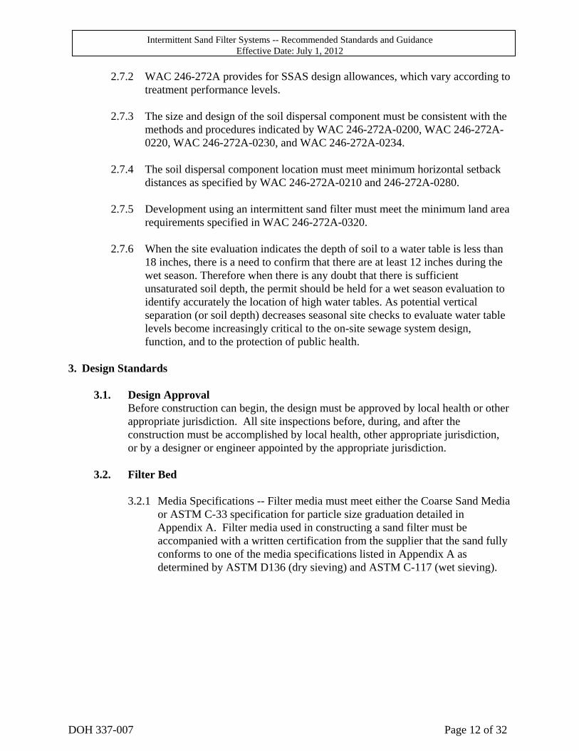
2.7.2 WAC 246-272A provides for SSAS design allowances, which vary according to treatment performance levels.
2.7.3 The size and design of the soil dispersal component must be consistent with the
methods and procedures indicated by WAC 246-272A-0200, WAC 246-272A-0220, WAC 246-272A-0230, and WAC 246-272A-0234.
2.7.4 The soil dispersal component location must meet minimum horizontal setback
distances as specified by WAC 246-272A-0210 and 246-272A-0280. 2.7.5 Development using an intermittent sand filter must meet the minimum land area
requirements specified in WAC 246-272A-0320. 2.7.6 When the site evaluation indicates the depth of soil to a water table is less than
18 inches, there is a need to confirm that there are at least 12 inches during the wet season. Therefore when there is any doubt that there is sufficient unsaturated soil depth, the permit should be held for a wet season evaluation to identify accurately the location of high water tables. As potential vertical separation (or soil depth) decreases seasonal site checks to evaluate water table levels become increasingly critical to the on-site sewage system design, function, and to the protection of public health.
3. Design Standards
3.1. Design Approval Before construction can begin, the design must be approved by local health or other appropriate jurisdiction. All site inspections before, during, and after the construction must be accomplished by local health, other appropriate jurisdiction, or by a designer or engineer appointed by the appropriate jurisdiction.
3.2. Filter Bed
3.2.1 Media Specifications -- Filter media must meet either the Coarse Sand Media
or ASTM C-33 specification for particle size graduation detailed in Appendix A. Filter media used in constructing a sand filter must be accompanied with a written certification from the supplier that the sand fully conforms to one of the media specifications listed in Appendix A as determined by ASTM D136 (dry sieving) and ASTM C-117 (wet sieving).
Intermittent Sand Filter Systems -- Recommended Standards and Guidance Effective Date: July 1, 2012
DOH 337-007 Page 13 of 32
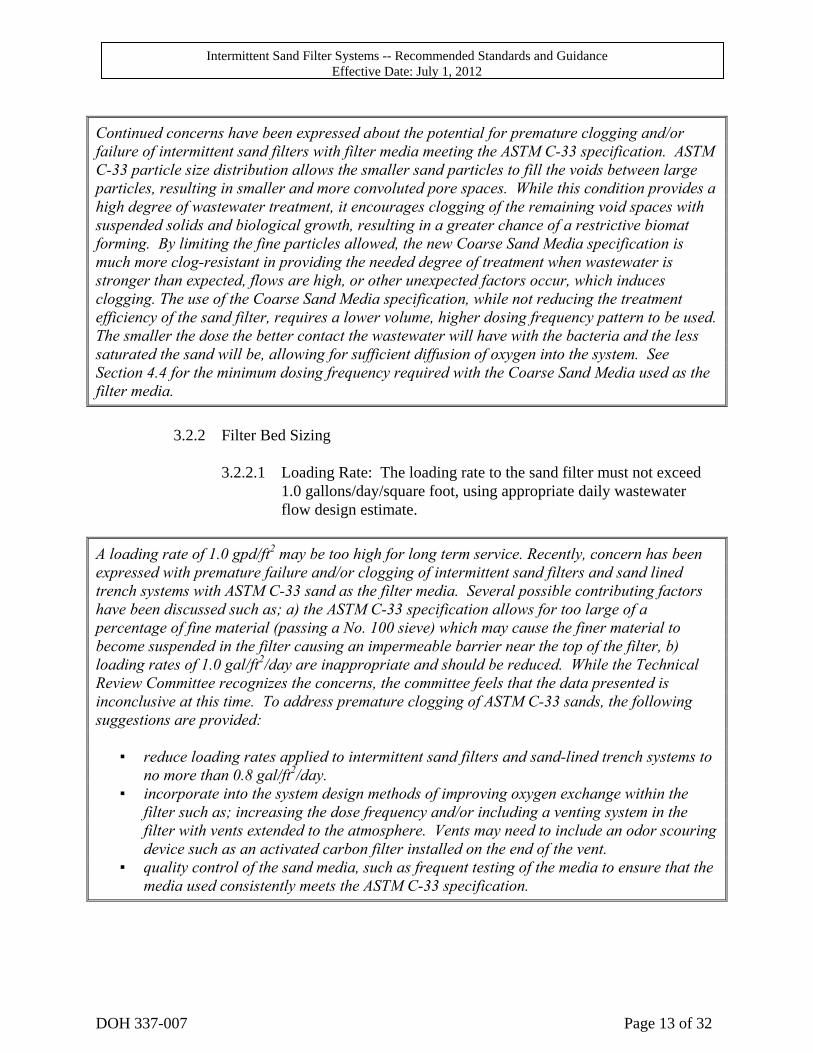
Continued concerns have been expressed about the potential for premature clogging and/or failure of intermittent sand filters with filter media meeting the ASTM C-33 specification. ASTM C-33 particle size distribution allows the smaller sand particles to fill the voids between large particles, resulting in smaller and more convoluted pore spaces. While this condition provides a high degree of wastewater treatment, it encourages clogging of the remaining void spaces with suspended solids and biological growth, resulting in a greater chance of a restrictive biomat forming. By limiting the fine particles allowed, the new Coarse Sand Media specification is much more clog-resistant in providing the needed degree of treatment when wastewater is stronger than expected, flows are high, or other unexpected factors occur, which induces clogging. The use of the Coarse Sand Media specification, while not reducing the treatment efficiency of the sand filter, requires a lower volume, higher dosing frequency pattern to be used. The smaller the dose the better contact the wastewater will have with the bacteria and the less saturated the sand will be, allowing for sufficient diffusion of oxygen into the system. See Section 4.4 for the minimum dosing frequency required with the Coarse Sand Media used as the filter media.
3.2.2 Filter Bed Sizing
3.2.2.1 Loading Rate: The loading rate to the sand filter must not exceed
1.0 gallons/day/square foot, using appropriate daily wastewater flow design estimate.
A loading rate of 1.0 gpd/ft2 may be too high for long term service. Recently, concern has been expressed with premature failure and/or clogging of intermittent sand filters and sand lined trench systems with ASTM C-33 sand as the filter media. Several possible contributing factors have been discussed such as; a) the ASTM C-33 specification allows for too large of a percentage of fine material (passing a No. 100 sieve) which may cause the finer material to become suspended in the filter causing an impermeable barrier near the top of the filter, b) loading rates of 1.0 gal/ft2/day are inappropriate and should be reduced. While the Technical Review Committee recognizes the concerns, the committee feels that the data presented is inconclusive at this time. To address premature clogging of ASTM C-33 sands, the following suggestions are provided: ▪ reduce loading rates applied to intermittent sand filters and sand-lined trench systems to
no more than 0.8 gal/ft2/day. ▪ incorporate into the system design methods of improving oxygen exchange within the
filter such as; increasing the dose frequency and/or including a venting system in the filter with vents extended to the atmosphere. Vents may need to include an odor scouring device such as an activated carbon filter installed on the end of the vent.
▪ quality control of the sand media, such as frequent testing of the media to ensure that the media used consistently meets the ASTM C-33 specification.
Intermittent Sand Filter Systems -- Recommended Standards and Guidance Effective Date: July 1, 2012
DOH 337-007 Page 14 of 32
3.2.2.2 Surface area of filter bed: The surface area must be determined by dividing the design flow estimate by the loading rate.
3.2.2.3 Depth of media: The media depth must be a minimum of 24 inches.
3.2.3 Filter bed containment: The filter bed is contained either in a flexible membrane-lined pit, or a concrete vessel. Design and construction must conform to the containment standards set forth in Appendix B.
3.3. Wastewater Distribution
3.3.1 Pressure distribution: Pressure distribution is required and must comply with
the pressure distribution standards and guidance. This requirement applies to all pressure distribution related components.
3.3.2 Wastewater application to the filter bed: The wastewater must be applied to
the layer of drain rock atop the filter media, or sprayed upward against the top of gravelless chambers.
3.4. Minimum Dosing Frequency:
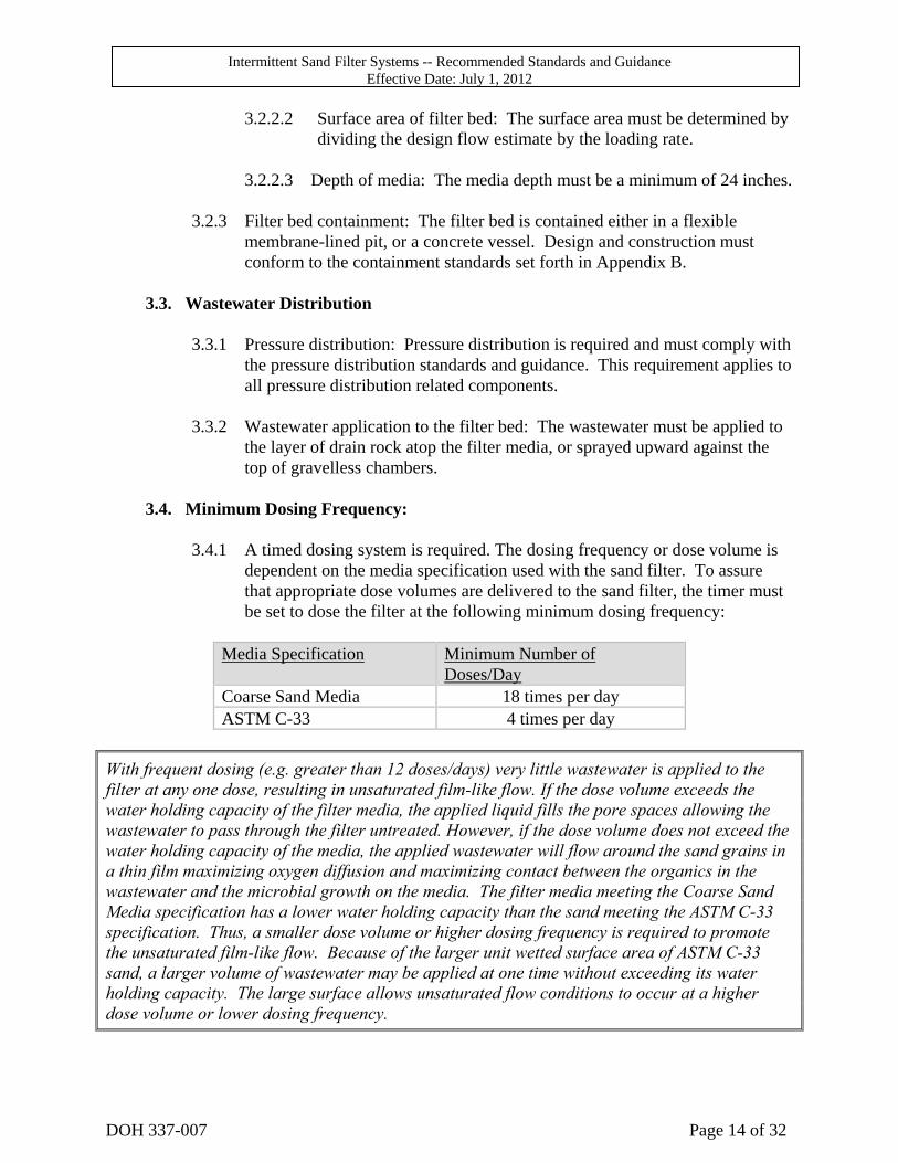
3.4.1 A timed dosing system is required. The dosing frequency or dose volume is
dependent on the media specification used with the sand filter. To assure that appropriate dose volumes are delivered to the sand filter, the timer must be set to dose the filter at the following minimum dosing frequency:
Media Specification Minimum Number of
Doses/Day Coarse Sand Media 18 times per day ASTM C-33 4 times per day
With frequent dosing (e.g. greater than 12 doses/days) very little wastewater is applied to the filter at any one dose, resulting in unsaturated film-like flow. If the dose volume exceeds the water holding capacity of the filter media, the applied liquid fills the pore spaces allowing the wastewater to pass through the filter untreated. However, if the dose volume does not exceed the water holding capacity of the media, the applied wastewater will flow around the sand grains in a thin film maximizing oxygen diffusion and maximizing contact between the organics in the wastewater and the microbial growth on the media. The filter media meeting the Coarse Sand Media specification has a lower water holding capacity than the sand meeting the ASTM C-33 specification. Thus, a smaller dose volume or higher dosing frequency is required to promote the unsaturated film-like flow. Because of the larger unit wetted surface area of ASTM C-33 sand, a larger volume of wastewater may be applied at one time without exceeding its water holding capacity. The large surface allows unsaturated flow conditions to occur at a higher dose volume or lower dosing frequency.
Intermittent Sand Filter Systems -- Recommended Standards and Guidance Effective Date: July 1, 2012
DOH 337-007 Page 15 of 32
3.5. Treated Wastewater (Filtrate) Collection and Discharge Filtrate may be collected and discharged from the bottom of the sand filter by either a gravity-flow underdrain, or a pumped-flow pumpwell system. When sand filters are membrane-lined, gravity flow underdrains must exit through a boot. The boot and exit pipe must be installed and tested according to the standards in Appendix C.
4. Operation, Monitoring, and Maintenance
4.1. Management The local health officer has the authority to require that an acceptable maintenance agreement be established, and supporting documents be developed and approved by the local health officer, prior to the issuance of approvals for a proposed sand filter sewage system. It is recommended that a maintenance agreement be required when, in the opinion of the local health authority, the ongoing operation of the sand filter sewage systems is best assured by the existence of such an agreement.
4.2. User’s Manual
A user’s manual for the sand filter system must be developed and / or provided by the system designer. These materials must contain the following, at a minimum:
4.2.1 Diagrams of the system components 4.2.2 Explanation of general system function, operational expectations, owner
responsibility, etc. 4.2.3 Names and telephone numbers of the system designer, local health authority,
component manufacturer, supplier/installer, and/or the management entity to be contacted in the event of a failure.
4.2.4 Information on the periodic monitoring and maintenance requirements of the
sewage system: septic tank, dosing tanks, sand-lined trenches, pumps, switches, alarms, etc.
4.2.5 Information on "trouble-shooting" common operational problems that might
occur. This information should be as detailed and complete as needed to assist the system owner to make accurate decisions about when and how to attempt corrections of operational problems, and when to call for professional assistance.
4.2.6 For proprietary sand filter devices, a complete maintenance and operation
document must be developed and provided by the manufacturer. This document must be made available, through the system designer, to the system owner. This document must include all the appropriate items mentioned above, plus any additional general and site-specific information useful to the system owner, and/or the maintenance person. A copy of this document must
Intermittent Sand Filter Systems -- Recommended Standards and Guidance Effective Date: July 1, 2012
DOH 337-007 Page 16 of 32
also be provided to the local health authority, prior to the issuance of the local installation permit.
4.3. Monitoring and Maintenance
4.3.1 Responsibility -- For the on-site sewage system to operate properly, its
various components need periodic monitoring and maintenance. Monitoring and maintenance are the responsibility of the homeowner, but may be best performed by experienced and qualified service providers. An Operation and Maintenance Manual must be developed and/or provided by the system designer with copies provided to the local health officer, system owner and maintenance contractor. The maintenance manual must include the following listed recommended maintenance descriptions and schedules. The local health officer may specify additional requirements.
4.3.2 Minimum Monitoring and Maintenance Description and Service Items
4.3.2.1 Type of use.
4.3.2.2 Age of system. 4.3.2.3 Specifications of all electrical and mechanical components installed
(occasionally components other than those specified on the plans are used).
4.3.2.4 Nuisance factors, such as odors or user complaints. 4.3.2.5 Septic tank: inspect yearly for structural integrity, proper baffling,
screen, ground water intrusion, and proper sizing. Inspect and clean effluent baffle screen and also pump tank as needed.
4.3.2.6 Pump chamber: clean the effluent screen (spraying with a hose is a
common cleaning method), inspect and clean the pump switches and floats yearly. Pump the accumulated sludge from the bottom of the chambers, whenever the septic tank is pumped, or more often if necessary.
4.3.2.7 Pumpwell: Inspect for infiltration, structural problems and improper
liquid level. Check for pump or siphon malfunctions, including problems related to dosing volume, pressurization, breakdown, clogging, burnout, or cycling. Pump the accumulated sludge from the bottom of the pumpwell, whenever the septic tank is pumped, or whenever necessary.
Intermittent Sand Filter Systems -- Recommended Standards and Guidance Effective Date: July 1, 2012
DOH 337-007 Page 17 of 32
The liquid level at the pump start or siphon must be below the bottom of the filter media in order to prevent ponding and rise of the capillary fringe in the sand. Improper liquid level (too high in the pumpwell) can result from improper setting of the pump on float, pump burnout, disconnected electrical supply to the pump or controls, or tripped circuit breaker. In some cases the underdrain may be underdesigned and may not have the flow capacity to supply the pump at the rate that it pumps. Infiltration into the pumpwell is serious and means that the effluent is entering the pumpwell before passing through the full column of sand. Effluent that is short circuiting will not receive full sand filter treatment.
4.3.2.8 Check monitoring ports for ponding. Conditions in the monitoring
ports must be observed and recorded by the service provider during all operation and maintenance activities for the intermittent sand filter and other system components. For reduced sized drainfields, these observations must be reported to the local health jurisdiction responsible for permitting the system.
4.3.2.9 Inspect and test yearly for malfunction of electrical equipment such
as timers, counters, control boxes, pump switches, floats, alarm system, junction box, or other electrical components, and repair as needed. System checks should include improper setting or failure, of electrical, mechanical, or manual switches.
4.3.2.10 Mechanical malfunctions (other than those affecting sewage pumps)
including problems with valves, or other mechanical or plumbing components.
4.3.2.11 Material fatigue, failure, corrosion problems, or use of improper
materials, as related to construction or structural design. 4.3.2.12 Neglect or improper use, such as loading beyond the design rate,
poor maintenance, or excessive weed growth. 4.3.2.13 Installation problems, such as improper location or failure to follow
design. 4.3.2.14 Overflow or backup problems where sewage is involved. 4.3.4.15 Specific chemical/biological indicators, such as BOD, TSS, fecal
coliforms, etc. Sampling and testing may be required by the local health officer on a case-by-case basis, depending on the nature of the problem, availability of laboratories, or other factors.
4.3.4.16 Information on the safe disposal of discarded filter media. See
Appendix E.
Intermittent Sand Filter Systems -- Recommended Standards and Guidance Effective Date: July 1, 2012
DOH 337-007 Page 18 of 32
4.4. Action Conditions
4.4.1 When an inspection, or any other observation, reveals either of the following
listed conditions, the owner of the system must take appropriate action, according to the direction and satisfaction of the local health officer:
4.4.1.1 drainfield system failure, as defined in WAC 246-272A-0010, or
4.4.1.2 a history of long-term, continuous and increasing ponding of
wastewater within the reduced-size drainfield, which if left unaddressed, may result in untimely failure.
4.4.2 Appropriate Actions Upon Identification of Action conditions:
4.4.2.1 repair or modification of the drainfield system, 4.4.2.2 expansion of the drainfield system, or 4.4.2.3 modifications or changes within the structure relative to wastewater
strength or hydraulic flows
The repair or modification required may include the installation of additional drainfield to enlarge the system to 100% of the initial design size. Repair or modification is not limited to this option. Local permits must be obtained before construction begins, according to local health department requirements. Any repair or modification activity must be reported as part of the monitoring activity for the site.
Intermittent Sand Filter Systems -- Recommended Standards and Guidance Effective Date: July 1, 2012
DOH 337-007 Page 19 of 32
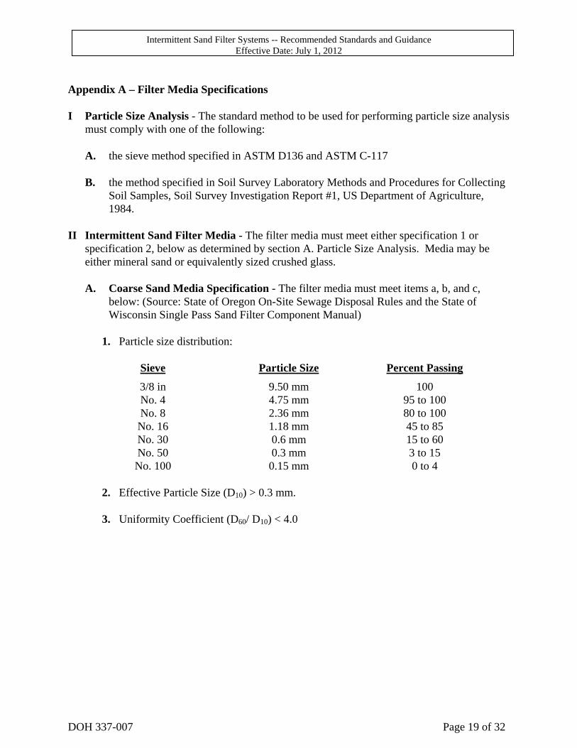
Appendix A – Filter Media Specifications I Particle Size Analysis - The standard method to be used for performing particle size analysis
must comply with one of the following:
A. the sieve method specified in ASTM D136 and ASTM C-117
B. the method specified in Soil Survey Laboratory Methods and Procedures for Collecting Soil Samples, Soil Survey Investigation Report #1, US Department of Agriculture, 1984.
II Intermittent Sand Filter Media - The filter media must meet either specification 1 or
specification 2, below as determined by section A. Particle Size Analysis. Media may be either mineral sand or equivalently sized crushed glass.
A. Coarse Sand Media Specification - The filter media must meet items a, b, and c,
below: (Source: State of Oregon On-Site Sewage Disposal Rules and the State of Wisconsin Single Pass Sand Filter Component Manual)
1. Particle size distribution:
Sieve Particle Size Percent Passing
3/8 in 9.50 mm 100 No. 4 4.75 mm 95 to 100 No. 8 2.36 mm 80 to 100 No. 16 1.18 mm 45 to 85 No. 30 0.6 mm 15 to 60 No. 50 0.3 mm 3 to 15 No. 100 0.15 mm 0 to 4
2. Effective Particle Size (D10) > 0.3 mm.
3. Uniformity Coefficient (D60/ D10) < 4.0
Intermittent Sand Filter Systems -- Recommended Standards and Guidance Effective Date: July 1, 2012
DOH 337-007 Page 20 of 32
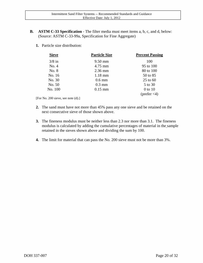
B. ASTM C-33 Specification - The filter media must meet items a, b, c, and d, below:
(Source: ASTM C-33-99a, Specification for Fine Aggregate)
1. Particle size distribution:
Sieve Particle Size Percent Passing
3/8 in 9.50 mm 100 No. 4 4.75 mm 95 to 100 No. 8 2.36 mm 80 to 100 No. 16 1.18 mm 50 to 85 No. 30 0.6 mm 25 to 60 No. 50 0.3 mm 5 to 30 No. 100 0.15 mm 0 to 10
(prefer <4) [For No. 200 sieve, see note (d).]
2. The sand must have not more than 45% pass any one sieve and be retained on the
next consecutive sieve of those shown above.
3. The fineness modulus must be neither less than 2.3 nor more than 3.1. The fineness modulus is calculated by adding the cumulative percentages of material in the sample retained in the sieves shown above and dividing the sum by 100.
4. The limit for material that can pass the No. 200 sieve must not be more than 3%.
Intermittent Sand Filter Systems -- Recommended Standards and Guidance Effective Date: July 1, 2012
DOH 337-007 Page 21 of 32
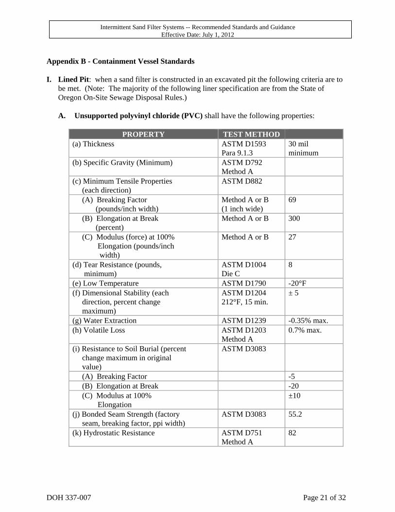
Appendix B - Containment Vessel Standards I. Lined Pit: when a sand filter is constructed in an excavated pit the following criteria are to
be met. (Note: The majority of the following liner specification are from the State of Oregon On-Site Sewage Disposal Rules.)
A. Unsupported polyvinyl chloride (PVC) shall have the following properties:
PROPERTY TEST METHOD
(a) Thickness ASTM D1593 Para 9.1.3
30 mil minimum
(b) Specific Gravity (Minimum) ASTM D792 Method A
(c) Minimum Tensile Properties (each direction)
ASTM D882
(A) Breaking Factor (pounds/inch width)
Method A or B (1 inch wide)
69
(B) Elongation at Break (percent)
Method A or B 300
(C) Modulus (force) at 100% Elongation (pounds/inch width)
Method A or B 27
(d) Tear Resistance (pounds, minimum)
ASTM D1004 Die C
8
(e) Low Temperature ASTM D1790 -20°F (f) Dimensional Stability (each direction, percent change maximum)
ASTM D1204 212°F, 15 min.
± 5
(g) Water Extraction ASTM D1239 -0.35% max. (h) Volatile Loss ASTM D1203
Method A 0.7% max.
(i) Resistance to Soil Burial (percent change maximum in original value)
ASTM D3083
(A) Breaking Factor -5 (B) Elongation at Break -20 (C) Modulus at 100% Elongation
±10
(j) Bonded Seam Strength (factory seam, breaking factor, ppi width)
ASTM D3083 55.2
(k) Hydrostatic Resistance ASTM D751 Method A
82
Intermittent Sand Filter Systems -- Recommended Standards and Guidance Effective Date: July 1, 2012
DOH 337-007 Page 22 of 32
B. Installation Standards:
1. Patches, repairs and seams shall have the same physical properties as the parent material;
2. Site considerations and preparation:
a. The supporting surface slopes and foundation to accept the liner shall be stable
and structurally sound including appropriate compaction. Particular attention shall be paid to the potential of sink hole development and differential settlement;
b. Soil stabilizers such as cementations or chemical binding agents shall not
adversely affect the membrane; cementations and chemical binding agents may be potentially abrasive agents.
3. Only fully buried membrane liner installation shall be considered to avoid
weathering;
4. Unreinforced liners have high elongation and can conform to irregular surfaces and follow settlements within limits. Unreasonable strain reduces thickness and may reduce life expectancy by lessening the chemical resistance of the thinner (stretched) material. Every effort shall be made to minimize the strain (or elongation) anywhere in the flexible membrane liner;
5. Construction and installation:
a. Bottom of pit
(1) Cover with sand to "bed" liner, adequate in depth (minimum 3") to protect
liner from puncture, or
(2) Use a non-woven needle-punched synthetic geotextile fabric, in a thickness appropriate to the tasks of protecting the liner.
(3) Regardless of whether sand or a fabric is used, grade the bottom to provide
a sloping liner surface, from the outer edge of the filter toward the point of underdrain collection. Slope equal to 8 inches fall overall or one inch of fall per foot of run, whichever is the greatest.
b. Sides of the pit - smooth, free of possible puncture points.
c. Climatic conditions:
(1) Temperature. The desirable temperature range for membrane installation is
42° F to 78° F. Lower or higher temperatures may have an adverse effect on transportation, storage, field handling and placement, seaming and

Intermittent Sand Filter Systems -- Recommended Standards and Guidance Effective Date: July 1, 2012
DOH 337-007 Page 23 of 32
backfilling and attaching boots and patches may be difficult. Placing liner outside the desirable temperature range shall be avoided;
(2) Wind. Wind may have an adverse effect on liner installation such as
interfering with liner placement. Mechanical damage may result. Cleanliness of areas for boot connection and patching may not be possible. Alignment of seams and cleanliness may not be possible. Placing the liner in high wind shall be avoided;
(3) Precipitation. When field seaming is adversely affected by moisture,
portable protective structures and/or other methods shall be used to maintain a dry sealing surface. Proper surface preparation for bonding boots and patches may not be possible. Seaming, patching and attaching ‘boots’ shall be done under dry conditions.
d. Boots: When boots are used (required when using a gravity-flow underdrain), the
boot and exit pipe must be installed with the following criteria:
(1) The system designer is to identify the use of a sand filter liner with underdrain and boot as a part of the application for on-site sewage system and provide specifications detailing design and installation requirements.
(2) The boot is to be installed by the manufacturer or the manufacturer's
representative.
(3) The boot outlet is to be bedded in sand.
(4) The boot is to be sized to accommodate a 4" underdrain outlet pipe.
(5) The boot is to be secured to the 4" outlet pipe with two (2) stainless steel bands and screws, and sealant strips as recommended by the manufacturer.
(6) The underdrain is to be designed in accordance with Appendix C,
Underdrains and exit the side of the liner.
(7) An inspection port must be installed in the sewer pipe from the sand filter to the drainfield.
(8) Sewer pipe from the sand filter to the drainfield must be ASTM 3034 ring
tight.
(9) The trench from the sand filter to the drainfield must be back-filled with a minimum 5 lineal feet clay dam to prevent the trench from acting as a conduit for ground water movement towards the drainfield.

Intermittent Sand Filter Systems -- Recommended Standards and Guidance Effective Date: July 1, 2012
DOH 337-007 Page 24 of 32
(10) If the boot may be submerged in a seasonal high water table, performance testing of the sand filter/boot for leakage must be conducted in the following manner:
(a) Block outlet pipe;
(b) Fill underdrain gravel with water;
(c) Measure and record elevation of water through observation/inspection
port;
(d) Let stand 24 hours minimum;
(e) Measure and record elevation of water through observation/inspection port;
(f) No allowable drop in the water level.
e. Liner Placement:
(1) Size. The final cut size of the liner shall be carefully determined and
ordered to generously fit the container geometry without field seaming or excess straining of the linear material;
(2) Transportation, handling and storage. Transportation, handling and storage
procedures shall be planned to prevent material damage. Material shall be stored in a secured area and protected from adverse weather;
(3) Site inspection. A site inspection shall be carried out by local health
officer, other appropriate jurisdiction or by a designer or engineer appointed by the appropriate jurisdiction and the installer prior to liner installation to verify surface conditions, etc.;
(4) Deployment. Panels shall be positioned to minimize handling. Seaming
should not be necessary. Bridging or stressed conditions shall be avoided with proper slack allowances for shrinkage. The liner shall be secured to prevent movement and promptly backfilled;
(5) Anchoring trenches. The liner edges should be secured frequently in a
backfilled trench;
(6) Field seaming. Field seaming, if absolutely necessary, shall only be attempted when weather conditions are favorable. The contact surfaces of the materials should be clean of dirt, dust, moisture, or other foreign materials. The contact surfaces shall be aligned with sufficient overlap and bonded in accordance with the suppliers recommended procedures.
Intermittent Sand Filter Systems -- Recommended Standards and Guidance Effective Date: July 1, 2012
DOH 337-007 Page 25 of 32
Wrinkles shall be smoothed out and seams should be inspected by non-destructive testing techniques to verify their integrity. As seaming occurs during installation, the field seams shall be inspected continuously and any faulty area repaired immediately;
(7) Field repairs. It is important that traffic on the lined area be minimized.
Any necessary repairs to the liner shall be patched using the same lining material and following the recommended procedure of the supplier;
(8) Final inspection and acceptance. Completed liner installations shall be
visually checked for punctures, rips, tears and seam discontinuities before placement of any backfill. At this time the installer shall also manually check all factory and field seams with an appropriate tool. In lieu of or in addition to manual checking of seams by the installer, either of the following tests may be performed;
(a) Wet Test: The lined basin shall be flooded to the one (1) foot level with
water after inlets and outlets have been plugged. There shall not be any loss of water in a 25-hour test period.
(b) Air Lance Test: Check all bonded seams using a minimum 50 PSI
(gauge) air supply directed through a 3/16 inch (typical) nozzle held not more than 2 inches from the seam edge and directed at the seam edge. Riffles indicate unbonded areas within the seam, or other undesirable seam construction.
II. Concrete Containment Vessel: to be designed and/or approved by a qualified professional
engineer if the following conditions are not met.
A. Above ground tank.
(1) Walls
(a) at least 6 inches thick
(b) 4 feet or less in height
(c) rebar reinforcement: 3/8 inch diameter rebar on 2-foot centers horizontally and vertically, with continuous lengths wrapped around the corners.
Intermittent Sand Filter Systems -- Recommended Standards and Guidance Effective Date: July 1, 2012
DOH 337-007 Page 26 of 32
(2) Floor
(a) at least 3 1/2 inches thick
(b) reinforced with steel mesh (CRSI standard #6-1010) to prevent cracking
and to maintain water-tightness
(3) Tank is to be designed, constructed, and sealed to be water-tight.
B. Below ground tank.
Any below-ground concrete tank must be water-tight. The design of any such tank is to be approved by a qualified professional engineer and, where required by local and/or state regulation, the local health officer.
Intermittent Sand Filter Systems -- Recommended Standards and Guidance Effective Date: July 1, 2012
DOH 337-007 Page 27 of 32
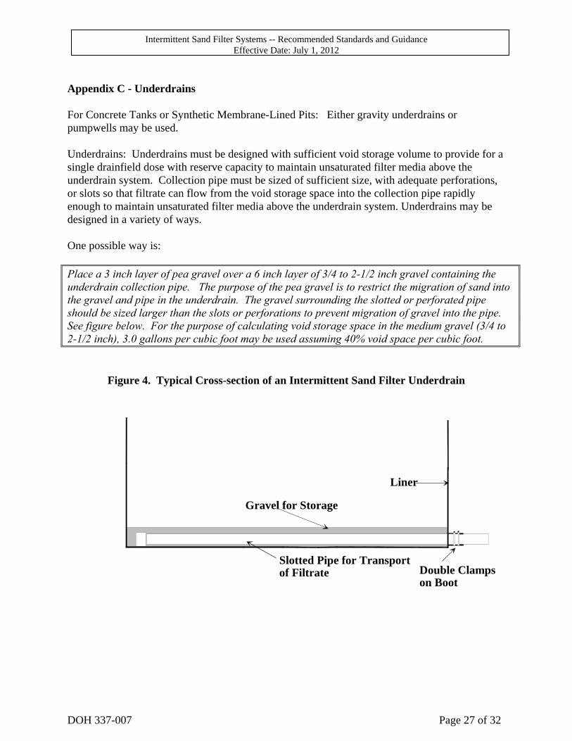
Appendix C - Underdrains For Concrete Tanks or Synthetic Membrane-Lined Pits: Either gravity underdrains or pumpwells may be used. Underdrains: Underdrains must be designed with sufficient void storage volume to provide for a single drainfield dose with reserve capacity to maintain unsaturated filter media above the underdrain system. Collection pipe must be sized of sufficient size, with adequate perforations, or slots so that filtrate can flow from the void storage space into the collection pipe rapidly enough to maintain unsaturated filter media above the underdrain system. Underdrains may be designed in a variety of ways. One possible way is: Place a 3 inch layer of pea gravel over a 6 inch layer of 3/4 to 2-1/2 inch gravel containing the underdrain collection pipe. The purpose of the pea gravel is to restrict the migration of sand into the gravel and pipe in the underdrain. The gravel surrounding the slotted or perforated pipe should be sized larger than the slots or perforations to prevent migration of gravel into the pipe. See figure below. For the purpose of calculating void storage space in the medium gravel (3/4 to 2-1/2 inch), 3.0 gallons per cubic foot may be used assuming 40% void space per cubic foot.
Figure 4. Typical Cross-section of an Intermittent Sand Filter Underdrain
Gravel for Storage
Slotted Pipe for Transportof Filtrate
Liner
Double Clampson Boot
Intermittent Sand Filter Systems -- Recommended Standards and Guidance Effective Date: July 1, 2012
DOH 337-007 Page 28 of 32
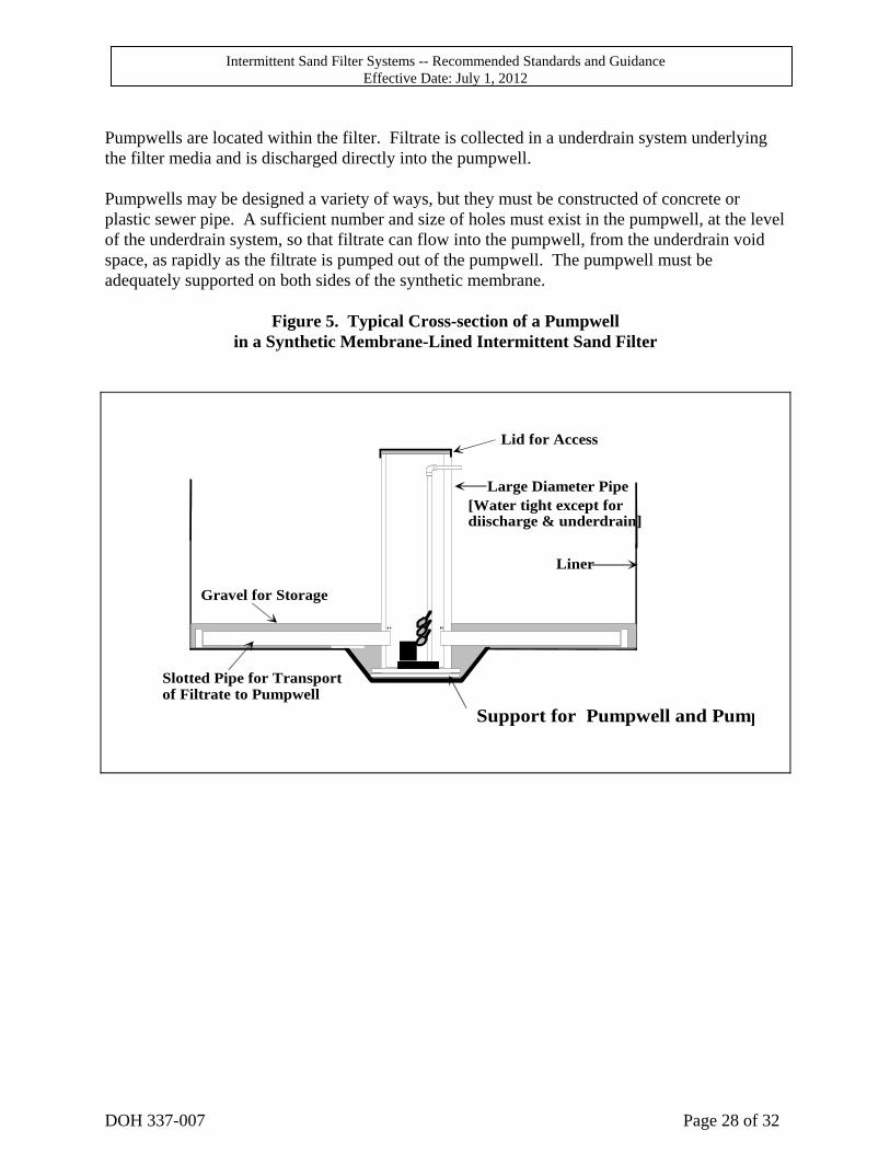
Pumpwells are located within the filter. Filtrate is collected in a underdrain system underlying the filter media and is discharged directly into the pumpwell. Pumpwells may be designed a variety of ways, but they must be constructed of concrete or plastic sewer pipe. A sufficient number and size of holes must exist in the pumpwell, at the level of the underdrain system, so that filtrate can flow into the pumpwell, from the underdrain void space, as rapidly as the filtrate is pumped out of the pumpwell. The pumpwell must be adequately supported on both sides of the synthetic membrane.
Figure 5. Typical Cross-section of a Pumpwell in a Synthetic Membrane-Lined Intermittent Sand Filter
Support for Pumpwell and Pump
Slotted Pipe for Transportof Filtrate to Pumpwell
Liner
Gravel for Storage
Large Diameter Pipe
Lid for Access
[Water tight except for diischarge & underdrain]
Intermittent Sand Filter Systems -- Recommended Standards and Guidance Effective Date: July 1, 2012
DOH 337-007 Page 29 of 32
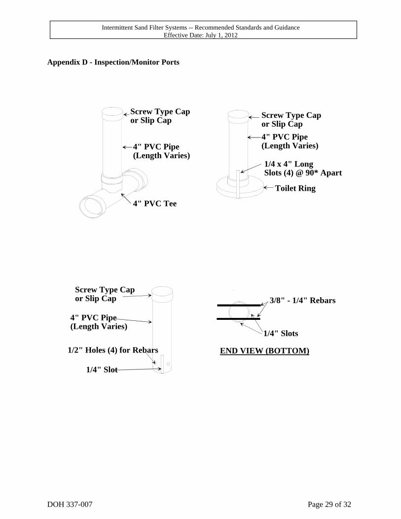
Appendix D - Inspection/Monitor Ports
Screw Type Capor Slip Cap
4" PVC Pipe(Length Varies)
4" PVC Tee
Screw Type Capor Slip Cap
4" PVC Pipe(Length Varies)
1/4 x 4" LongSlots (4) @ 90* Apart
Toilet Ring
Screw Type Capor Slip Cap
1/4" Slot
1/2" Holes (4) for Rebars
4" PVC Pipe(Length Varies)
3/8" - 1/4" Rebars
1/4" Slots
END VIEW (BOTTOM)
Intermittent Sand Filter Systems -- Recommended Standards and Guidance Effective Date: July 1, 2012
DOH 337-007 Page 30 of 32
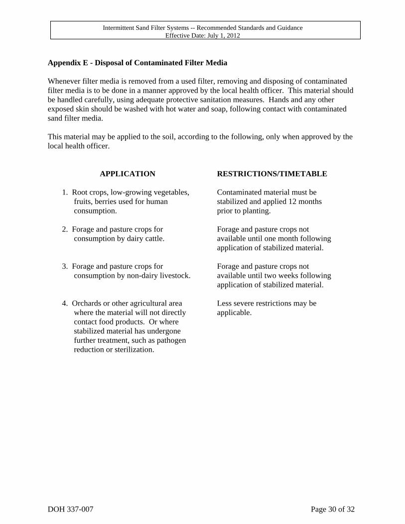
Appendix E - Disposal of Contaminated Filter Media Whenever filter media is removed from a used filter, removing and disposing of contaminated filter media is to be done in a manner approved by the local health officer. This material should be handled carefully, using adequate protective sanitation measures. Hands and any other exposed skin should be washed with hot water and soap, following contact with contaminated sand filter media. This material may be applied to the soil, according to the following, only when approved by the local health officer.
APPLICATION RESTRICTIONS/TIMETABLE
1. Root crops, low-growing vegetables, fruits, berries used for human consumption.
Contaminated material must be stabilized and applied 12 months prior to planting.
2. Forage and pasture crops for
consumption by dairy cattle. Forage and pasture crops not available until one month following application of stabilized material.
3. Forage and pasture crops for
consumption by non-dairy livestock. Forage and pasture crops not available until two weeks following application of stabilized material.
4. Orchards or other agricultural area
where the material will not directly contact food products. Or where stabilized material has undergone further treatment, such as pathogen reduction or sterilization.
Less severe restrictions may be applicable.

Intermittent Sand Filter Systems -- Recommended Standards and Guidance Effective Date: July 1, 2012
DOH 337-007 Page 31 of 32
Appendix F - Bibliography Boyle, W.C. and Richard J. Otis, "On-Site Treatment", EPA Training Manual, Prepared for Environmental Research Information Center, ORD, USEPA, July 1979. Converse, Matthew M., A Field Evaluation of Single Pass Sand Filters in a Northern Climate, Masters Degree Thesis, Master of Science, University of Wisconsin-Madison, 1999. Design Manual: On-site Wastewater Treatment and Disposal Systems. U.S. EPA, EPA-625/1-80-012 October 1980 Final Report, Oregon On-site Experimental Systems Program, December 1982; Oregon Department of Environmental Quality Glossary of Water and Wastewater Control Engineering; Joint Editorial Board of the AWWA, WPCF, ASCE, APHA, Copyright 1969 Gross, Mark A., Optimum Depth of Sand for Filtering Septic Tank Effluent; Masters Degree Thesis, Master of Science, University Of Arkansas, 1981. Gross, Mark, Dee T. Mitchell, Biological Virus Removal from Household Septic Tank Effluent; Proceedings of the Fourth National Symposium on Individual and Small Community Sewage Systems, ASAE, December 1984, New Orleans, Louisiana. Gross, Mark, Ph.D., P.E., Dee Mitchell, Household Wastewater Virus Removal by Sand Filtration; 1988 Revision. Hathaway, Randy J., Dee T. Mitchell, Sand Filtration of Septic Tank Effluent For All Seasons Disposal By Irrigation, Proceedings of the Fourth National Symposium on Individual and Small Community Sewage Systems, December 1984, New Orleans, Louisiana Hines, Michael and R.E. Favreau, Recirculating Sand Filter: An Alternative to Traditional Sewage Absorption Systems, Proceedings of National Home Sewage Disposal Symposium, December 1974. Koerner, Robert M., Ph.D., P.E., Designing with Geosynthethics, Prentice-Hall Loudon, T.L., G.L. Birnie, Jr., Performance of Trenches Receiving Sand Filter Effluent in Slowly Permeable Soils, Proceedings of the 6th National Symposium on Individual and Small Community Sewage Systems, ASAE, December, 1991, Chicago, IL. Management of Small Waste Flows, Final Report of the Small Scale Management Project, University of Wisconsin, EPA 600/2-78-173.
Intermittent Sand Filter Systems -- Recommended Standards and Guidance Effective Date: July 1, 2012
DOH 337-007 Page 32 of 32
Mitchell, Dee, Sand Filtration of Septic Tank Effluent, Proceedings of the 5th Northwest On-site Wastewater Treatment Short Course, University of Washington, September 1985 Mitchell, Mike D. P.E., Writings, Northwest Septic, Inc., Mt. Vernon, Washington. On the Performance of Experimental Sand Filters in the State of Oregon, Oregon Department of Environmental Quality. Otis, Richard, P.E., Soil Clogging: Mechanisms and Control, Proceedings of the 4th National Symposium on Individual and Small Community Sewage Systems, ASAE, December 1984, New Orleans, LA. Otis, Richard J., P.E., On-site Wastewater Treatment Intermittent Sand Filters, Rural Systems Engineering, Madison, Wisconsin. Sauer, D.K., W.C. Boyle, and Richard J. Otis. "Intermittent Sand Filtration." ASCE/EE, August 1976 Scherer, Billy P., Dee T. Mitchell, Individual Household Surface Disposal of Treated Wastewater without Chlorination; Proceedings of the Third National Symposium on Individual and Small Community Sewage Treatment, December 1981, Chicago, Illinois. Siegrist, Robert L., Hydraulic Loading Rates for Soil Absorption Systems Based on Wastewater Quality, Proceedings of the 5th National Symposium on Individual and Small Community Sewage Systems, ASAE, December 1987, Chicago, IL Technology Assessment of Intermittent Sand Filters. U.S. EPA, Office of Municipal Pollution Control, Project Officer: James F. Kreissl. Authors: Damann L. Anderson, Robert L. Seigrist, Richard J. Otis. Tyler, E. Jerry, James C. Converse, Soil Acceptance of Onsite Wastewater as Affected by Soil Morphology and Wastewater Quality, Proceedings of the 7th International Symposium on Individual and Small Community Sewage Systems, ASAE, December 1994, Atlanta, GA.