design guidelines for granular particles in a conical ... · design guidelines for granular...
TRANSCRIPT

Design guidelines for granular particles in a conical
centrifugal filter
A.F.M. Bizarda, D.D. Symonsa,∗, N.A. Flecka, G.C. Grimwoodb
aCambridge University Engineering Department,Trumpington Street, Cambridge, CB21PZ, UK
bThomas Broadbent and Sons Ltd., Queen Street South, Huddersfield, HD1 3EA, UK
Abstract
Essential design criteria for successful drying of granular particles in a con-
ical continuous centrifugal filter are developed in a dimensionless fashion.
Four criteria are considered: minimum flow thickness (to ensure sliding bulk
flow rather than particulate flow), desaturation position, output dryness and
basket failure. The criteria are based on idealised physical models of the
machine operation and are written explicitly as functions of the basket size
lout, spin velocity Ω and input flow rate of powder Qp. The separation of su-
crose crystals from liquid molasses is taken as a case study and the successful
regime of potential operating points (lout, Ω) is plotted for a wide range of
selected values of flow rate Qp. Analytical expressions are given for minimum
and maximum values of the three independent parameters (lout, Ω, Qp) as a
function of the slurry and basket properties. The viable operating regime for
a conical centrifugal filter is thereby obtained as a function of the slurry and
basket properties.
∗Corresponding author. Email: Tel: +44 1223 760502; Fax: +44 1223 332662Email address: [email protected] (D.D. Symons)URL: http://www-edc.eng.cam.ac.uk/people/dds11.html (D.D. Symons)
Preprint submitted to Chemical Engineering Research and Design July 6, 2012

Keywords: design, filtration, centrifugation, powders, separation, drying
Nomenclature
List of Roman symbols
Bo Bond number
Ci Dimensionless limit for criteria i
K Carman-Kozeny permeability empirical constant
M Liquid mass fraction
Ncap Capillary number
Q Volumetric flow rate
R Dimensionless radial position
Ro Rossby number
S Relative saturation
Xi Dimensionless group for criteria i
Z Ratio of fluid drainage and powder sliding velocities
a Slip velocity dependency coefficient for wall shear traction
a Dimensionless empirical slip velocity dependency parameter
b Coefficient of friction for powder against wall
b Ratio of the coefficient of friction b to the cone slope tanα
dp Average particle size
d Minimum through-thickness number of particles for sliding bulk flow
g Acceleration due to gravity
g∗ Centripetal acceleration
h Thickness
kp Powder permeability
2

k Dimensionless empirical coefficient for powder permeability
lout Basket radius at outlet in cylindrical co-ordinates
m Total input mass flow rate of slurry
np Powder porosity
p Pressure
q Superficial velocity of liquid through thickness of powder cake
r Radial position in a spherical co-ordinate system
s Particle specific area
u Through thickness averaged radial velocity
v Local radial velocity
vout Circumferential velocity at outlet
z Through-thickness co-ordinate, origin z=0 at the wall
3

List of Greek symbols
Σ Design space
Ψ Particle sphericity
Ω Cone angular velocity
α Cone semi-angle
γ Fluid surface tension
ζ Safety factor for basket failure
θ Polar angle
κ Ratio of permeability of screen and powder
µf Fluid dynamic viscosity
ξ Dimensionless position of the desaturation point
ρ Density
ρ Ratio of the powder density to that of the fluid
σ Normal stress
τ Shear stress
ϕ Hoop angle
4

List of subscripts
b Basket (cone)
bkf Basket failure
conv Fluid convected by powder movement
dry Target dryness condition
eff Effective
f Fluid
i Criteria: 1) bulk flow, 2) desaturation, 3) dryness, 4) basket failure
in Inlet
out Outlet
p Powder or particle
ref Reference value
seep Fluid seepage through powder
tot Total (fluid and solid)
y Yield (of basket)
1. Introduction
1.1. Centrifugal filters
Centrifugal filters are commonly used in the food processing and chemical
industries in order to separate the liquid and solid phases of a mixture. There
exist two main types of centrifugal filter: batch machines with a cylindrical
basket and continuous machines with a conical basket. The present study
focuses on continuous conical centrifuges, which are most commonly used in
the sucrose industry to separate sucrose crystals from molasses. Swindells
(1982) and Greig (1995) studied the functioning of these machines in a semi-
5

empirical fashion. While their work provides valuable insight into the oper-
ation of conical centrifuges in the sucrose industry it does not fully address
the underlying mechanics. Consequently, only a limited number of operat-
ing parameters have been used to optimize the design and operation of the
sucrose machine. Application of the results for sucrose to pharmaceutical,
chemical or other food products has also proved difficult. This study aims to
provide fundamental guidelines for the design of a conical centrifugal filter,
based upon idealised physical models of the machine.
1.2. Typical operation of a continuous centrifuge
The operation of a continuous conical centrifuge is now described through
the example of a typical sucrose industry machine. The rotating conical
basket of the machine, sketched in Fig.1, has a jump in cone angle along
its length: a lower impervious cone has a semi-angle of α = 15 whereas the
upper perforated cone has a semi-angle of α = 30. The basket is about 1m in
diameter at outlet and spins at 1800 RPM to provide a maximum centripetal
acceleration of 2000g. The inside wall of the upper, perforated cone is fitted
with a slotted screen, thereby allowing for fluid drainage but preventing
powder losses, see Fig.1. The feedstock, in the form of a sucrose/molasses
slurry (massecuite) of mass moisture fraction Min ≈50% and temperature
60C, is introduced along the spin axis into the lower impervious cone at
a constant mass flow rate m. The slurry acquires the angular velocity of
the basket Ω and migrates up the wall of the cone under centrifugal force.1
1Most of the tangential acceleration occurs in an acceleration cone which deposits the
slurry onto the lower impervious cone at an angular velocity already close to Ω.
6

Sedimentation of the sucrose crystals in the lower impervious cone causes the
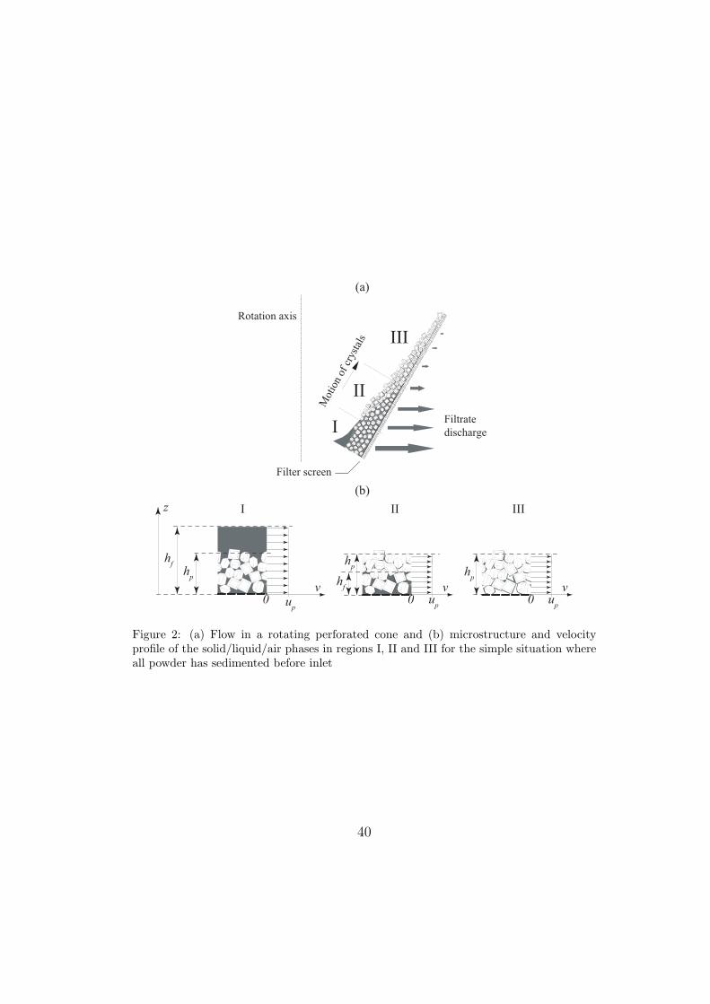
crystals to tend to settle, and then slide, against the smooth cone wall. Three
distinct regions labelled I to III can be identified in the upper perforated cone
as indicated in Fig.2a. An idealised microstructure may be assumed to exist
in each region, see Fig.2b. In region I the flow is in the over-saturated state:
the sucrose crystals have settled into a densely packed layer of height hp,
whereas the excess fluid exists to a height hf > hp, as shown.2
Liquid drainage causes the slurry to evolve into an under-saturated cake
of densely packed powder of height hp in region II. In region II the upper
portion of the powder cake is damp and coated with a thin liquid film, while
the bottom portion (of height hf ) is still saturated with fluid. Finally in
region III, providing the centripetal acceleration is sufficient to overcome
capillary forces, the powder is desaturated and only a residual liquid fraction
wets the surface of the crystals. The flow in region III consists of a cake of
damp powder, of height hp, sliding over the screen. Region II is therefore
the transition zone between flow of over-saturated powder (region I) and
flow of damp powder (region III) and is commonly called the colour line in
the sucrose industry. Further liquid drainage in region III is assumed to be
negligible and the damp powder in this region is treated as a homogeneous
continuous medium of constant properties.
2Here we assume complete initial settlement of the solid phase occurs in the lower
impervious cone. In a previous study (Bizard and Symons, 2011) we have compared this
assumption with the other extreme of nil settlement at the start of region I. The effect on
the downstream regions II and III was found to be negligible.
7

1.3. Outline of paper
The analysis begins by stating the governing field equations and consti-
tutive law that are assumed to apply in the upper, perforated cone. It is
assumed that the feed is a suspension of coarse granular material that set-
tles to an incompressible close packed bed which slips against the cone wall.
Essential design criteria are then derived for the successful operation of a
conical centrifuge. Restrictions on the input flow rate, outlet circumferential
velocity and centripetal acceleration to give successful operation are then
obtained from these criteria. Finally, a practical application of this analy-
sis is presented in the form of design maps for the typical case of sucrose
massecuite separation.
2. Governing field equations and the constitutive law
Equilibrium, continuity and constitutive relationships for idealised damp
granular flow in a spinning cone are now presented. These relationships are
then used to define reference values for flow velocity and thickness that are
used throughout this paper.
2.1. Equilibrium
A spherical co-ordinate system (r, θ, ϕ) (see Fig.3) is appropriate for de-
scribing the flow in a conical centrifugal filter. In most practical situations
the flow in the cone is slender: its thickness h is significantly smaller than
the radial co-ordinate r. A boundary layer approximation of the momen-
tum equations is therefore applicable. This approach to analysis of flow in
a spinning cone has been adopted by Bruin (1969) and Makarytchev et al.
8

(1997, 1998) for a Newtonian viscous fluid, and by Symons (2011a) for a
damp powder.
The relative importance of convective, Coriolis and centripetal accelera-
tions in the momentum equations (when written in a rotating frame of refer-
ence) may be assessed via the Rossby number Ro as defined by Makarytchev
et al. (1997):
Ro =u
rΩ sinα≈ convective
Coriolis≈ Coriolis
centripetal(1)
where u is the through-thickness averaged radial velocity, Ω the angular ve-
locity of the cone and α is the cone apex angle. In this study we assume
that the Rossby number is significantly smaller than unity, so that both con-
vective and Coriolis accelerations are negligible compared to the centripetal
acceleration. This assumption is in accordance with observations of typical
slender, high viscosity flows observed in industrial conical centrifuges. A
consequence of a small Rossby number (i.e. low radial velocity) is that the
circumferential slip (in the ϕ-direction) is negligible and therefore the flow
has virtually the same angular velocity as the cone at any radius r (see e.g.
Symons (2011a), Symons (2011b)). Analysis is further simplified by assum-
ing that gravity g may be neglected compared to the centripetal acceleration.
Given that the three dimensionless groups h/r, Ro and g/rΩ2 sinα are all
much less than unity the flow momentum equations may be reduced to the
equilibrium statements
∂ptot∂z
= −ρg∗ cosα (2)
∂τ
∂z= −ρg∗ sinα (3)
9

where ptot and τ are the total normal and shear stresses within the flow (see
Fig. 3), z is the through-thickness co-ordinate (z ≈ r(α − θ) where z ≪ r
and thus ∂z = −r∂θ ), ρ is the local density and
g∗ = rΩ2 sinα (4)
is the centripetal acceleration. At the free-surface of the flow (z = h) ptot =
τ = 0 and therefore (2-3) reduce to
τ = ptot tanα (5)
throughout the flow thickness at any r.
2.2. Continuity
Assume that the granular particles form an approximately incompressible,
densely packed cake with a porosity np that is constant throughout the cone.
Then, conservation of the volumetric flow rate Qp of the powder (including
voids) dictates that
Qp = 2πruphp sinα (6)
Also, note that Qp is specified by the total mass flow rate of slurry at inlet
m via
Qp =(1−Min)m
(1− np)ρp(7)
where ρp is the density of the powder solid parent material.
2.3. Constitutive behaviour
Industrial conical centrifuges are typically designed so that the cone an-
gle α is less than the angle of internal friction of the granular material,
but just greater than the angle of friction for contact with the basket wall
10

(Swindells, 1982). Consequently the granular material slips on the internal
surface of the cone rather than shearing internally. Slip is favoured by the
use of smooth perforated screens with a perforation area fraction of 10-15%.
The screen construction entails plates with slotted perforations or ”wedge-
wire sections”, and the slot width is significantly less than the mean granule
diameter (e.g. 75µm and 500µm, respectively, for a typical sucrose screen
and sucrose crystals), see e.g. Leung (1998) or Grimwood (2005). Bizard
et al. (2011) have reviewed interfacial friction laws for slurries, pastes and
damp powders and propose a velocity and pressure dependent law for the
shear traction τ acting on a sliding wet granular material of the form
τ = aup + bpeff (8)
where a is the slip velocity dependency coefficient, up the sliding velocity, b
the friction coefficient and peff the interfacial effective pressure, defined as
the difference between total and fluid pressures,
peff = ptot − pf (9)
Note that peff is the effective normal stress acting within the solid phase
or, in this particular case, between the solid phase and the screen wall, as
defined by Terzaghi (1943).
Yilmazer and co-authors (Yilmazer and Kalyon, 1989; Soltani and Yil-
mazer, 1998) performed sliding friction experiments on densely packed sus-
pensions of granular material within a Newtonian fluid and found the viscous
slip coefficient a to be
a =aµf
dp(10)
11
where a is a dimensionless coefficient on the order of 25, µf is the interstitial
fluid viscosity and dp is the average particle size. For completeness we note
that the coefficient a as given by (10) is only valid when the interface particles
are completely immersed in liquid, so that this relation may not strictly apply
to region III. It may be expected that a will decrease in region III due to the
reduction in liquid content at the interface. We will however assume that
the drain height (i.e. capillary rise height) as defined by Dombrowski and
Brownell (1954) is of the same order of magnitude as the mean particle size,
so that a in region III takes the same value given by (10) for regions I and
II.
Since the cake of granular material slides on the surface of the cone rather
than shears internally the dominant component of the radial velocity v is the
sliding velocity up. We therefore assume that v is equal to up throughout
the thickness of the densely packed powder. Furthermore, we will make the
simplifying assumption that viscous shear in the excess fluid in Region I can
be neglected so that v(z, r) ≈ up(r) for all z in all three regions, see Fig.2b.
2.4. Reference flow velocity and thickness
It is convenient to introduce a reference flow velocity uref and thickness
href in order to generate non-dimensional quantities later in the analysis.
Consider the sliding flow of damp powder in Region III. The total pressure
ptot applied to the screen by the cake of thickness hp and porosity np, under
the centripetal acceleration g∗ = rΩ2 sinα, is obtained from (2) as
ptot = (1− np) ρprΩ2hp sinα cosα at z = 0 (11)
12
A negligible quantity of fluid coats the powder, and so
peff = ptot (12)
The equilibrium, continuity and constitutive relationships (5-8, 6-12) can be
combined to give the velocity uref at which damp (almost dry) powder slides
in a spinning cone
uref ≡ Ω
(1− b
)(1− np)ρpQp sinα
2πa
1/2
(13)
where b is the ratio of friction coefficient to basket slope
b =b
tanα(14)
Note that the flow velocity is up = uref throughout region III and is inde-
pendent of r. Making use of (6,13) a reference flow thickness may be defined
as
href ≡ 1
rinΩ
aQp
2π(1− b
)(1− np) ρp sin
3 α
1/2
(15)
where rin is the inlet radius of the perforated basket, see Fig.3.
The associated flow thickness profile hp(r) in region III can therefore be
obtained from (6) and (15) as
hp =rinrhref (16)
3. Design criteria
Four criteria are proposed for satisfactory operation of a conical centrifu-
gal filter:
13
(1) the flow must be sufficiently thick in order for the damp particles to slide
as a bulk instead of individually slipping or rolling
(2) the desaturation point must be within the cone
(3) the residual liquid content (i.e. dryness) at outlet must be satisfactory
(4) the basket structure must not fail under centrifugal loading
Note that of these criteria only (4) is an absolute design requirement. A
centrifuge could be operated outside the limits defined by (1) to (3), but may
then fall outside the modelling assumptions of this paper. These criteria are
now presented in mathematical form.
3.1. Minimum flow thickness
In order for the centrifuge to process a large flow rate in a steady manner
the flow must not be too thin, otherwise the particles will slip and roll as
individual grains instead of sliding as a bulk. We term this undesirable
regime particulate flow, in contrast with the normal bulk flow. We write the
minimum required thickness as a multiple of the mean particle size dp:
hp ≥ ddp (17)
where d is the minimum through-thickness number of particles. In practice
the value of d required to ensure bulk flow is expected to be a function of, for
example, particle shape and surface roughness. For the purpose of numerical
illustrations in this paper we make the, somewhat arbitrary, choice of d=2.
Consider the case of a machine where the desaturation point is reached
within the basket, so that the uppermost part of the cone is in the damp
powder flow regime (region III in Fig.2). The minimum thickness is at the
14

outlet, see (16). Upon making use of (10) and (15-16) we can re-write the
condition for bulk flow (17) in non-dimensional form as
hp(rout)
ddp=
1
ddpΩlout
aµfQp
2π(1− b
)(1− np) ρpdp sinα
1/2
≥ 1 (18)
where lout = rout sinα, see Fig.3.
3.2. Desaturation position
In order to ensure that damp powder rather than a saturated paste ex-
its the centrifuge, region III should comprise a significant fraction of the
centrifuge conical basket. This is the same as requiring that region II ends
well before outlet, see Fig.2. Restated, the radial coordinate at which the
saturation S reaches zero rS=0 is less than the basket size rout:
rS=0 − rinrout − rin
≤ ξ (19)
where rin is the start of the perforated cone and ξ is a target dimensionless
number that defines the maximum desired position of the desaturation point.
For example, the choice ξ = 1/2 implies that the desaturation point must
be in the lower half of the basket. In order to remove impurities from the
crystals it is often required that a wash liquid is sprayed on the cake in
regions II and III. An important requirement for efficient powder washing is
the distance between the end of region II (r = rS=0) and the lip (r = rout).
This is controlled by the choice of parameter ξ. In the sucrose industry ξ is
typically 1/3, so that the top two thirds of the basket is available for powder
washing.
The position of the desaturation point depends upon the relative mag-
nitude of through-thickness drainage velocity and radial flow velocity. We
15

will first present some results from the literature concerning fluid drainage,
and upon combining these results with an idealised model for the radial flow
in the cone we will obtain an expression for the desaturation position rS=0.
For clarity the details of this idealised model for desaturation position are
presented in Appendix A; only essential results are given in the main section
of this work.
Centrifugal filter screens are designed in order to favour sliding (Leung,
1998) and minimize crystal losses whilst providing for minimal resistance
to drainage. For simplicity we assume that the screen’s resistance to fluid
drainage is negligible compared to the resistance of the densely packed pow-
der cake itself. Furthermore we assume that the cake is approximately in-
compressible with a constant permeability.3
The volumetric flow rate per unit area of fluid through a saturated powder
layer q in regions I and II is obtained via Darcy’s law (Darcy, 1856), as given
by
q =kpµf
(ρfg
∗ cosα +∂p
∂z
)(20)
where kp is the powder permeability, ρf the fluid density and ∂p/∂z the
pressure gradient across the powder cake. We note that Darcy’s law can
be used in region II because surface tension effects are treated as negligible.
The permeability kp of a powder of mean particle size dp and of porosity
np has been estimated by Carman (1956) by considering Poiseuille flow of
a Newtonian fluid through a bundle of capillaries. The resulting Carman-
3Here we assume coarse granular particles. For a compressible slurry of fine particles
or flocculated/coagulated suspensions a compression rheology model may be required, see
e.g. Barr and White (2006).
16

Kozeny equation is
kp =1
Ks2n3p
(1− np)2(21)
where K is a constant which depends upon the particle size distribution and
shape. K has a value close to 5 for most common soils (Carman, 1956)
and varies from 2 to 5.5 for sucrose crystals (Greig, 1995). s is the specific
surface of the particles (the ratio of particle surface area to volume) and can
be expressed in terms of the particle diameter dp and sphericity Ψ via
s =6
Ψdp(22)
For simplicity, we shall introduce an empirical parameter k to take the par-
ticle size distribution and shape into account and re-write (21-22) as
kp = kd2p (23)
The relation (23) is useful to make explicit the dependence of kp upon the
particle average size dp and will be used below.
The desaturation position rS=0 is estimated via a much simplified version
of the more complete model presented in Bizard and Symons (2011), see
Appendix A. Key simplifications for flow in regions I to III are listed here:
• Full sedimentation has occurred in the lower impervious cone, prior to
rin
• The radial velocity is equal to the basal sliding velocity through the
whole thickness of the flow (v(r, z) = up(r))
• The sliding velocity up in each region is taken to be constant throughout
that region
17

• Screen resistance to drainage is negligible compared to the resistance
of the densely packed powder cake
Upon making use of these assumptions we obtain (see Appendix A) the
position of the desaturation point as
r3S=0 = r3in +3 (ln [np(Sin − 1) + 1] + np)
2π sin2 α cosα
µfQp
Ω2ρfkp(24)
Sin is the saturation of the input slurry, defined as the ratio of the volume
of fluid at inlet to the volume of the pores in the powder, assuming that the
powder is densely packed and of porosity np. Thus,
Sin =(1− np)Minρpnp(1−Min)ρf
(25)
3.3. Dryness of output powder
An important feature of a centrifugal filter is how much residual liquid
remains within the cake of solid particles after the majority of the liquid
has been removed by drainage. Wakeman (Wakeman, 1977; Wakeman and
Tarleton, 1999) has shown experimentally that the drying efficiency of a
batch centrifuge is closely related to the value of a non-dimensional capillary
number
Ncap =n3pd
2pρfg
∗
4π2(1− np)2γ(26)
where γ is the fluid surface tension and g∗ is the centripetal acceleration in
the basket. Wakeman gives the following experimental corellation between
the ultimate relative saturation of centrifugally dried powders S∞ and the
capillary number Ncap as
S∞ = 0.0524N−0.19cap for 10−5 ≤Ncap ≤ 0.14 (27)
S∞ = 0.0139N−0.86cap for 0.14 ≤Ncap (28)
18
(27-28) are plotted in Fig.4. Note that the relation between the moisture
mass ratio at outlet Mout and the final relative saturation writes
S∞ =(1− np)Moutρpnp(1−Mout)ρf
(29)
Wakeman’s capillary number is equivalent to the more general Bond (or
Eotvos) number Bo = ρfg∗L2/γ which is a measure of the importance of
surface tension effects compared to body forces for a characteristic length
scale L. Wakeman’s results suggest that efficient centrifugal drying requires
a capillary number Ncap > 0.14. For a typical powder porosity of np=0.4 this
is equivalent to Bo > 30.
In the case of a conical centrifugal filter we note that drainage out of
the basket is driven by the component of the centripetal acceleration normal
to the screen g∗ cosα. In addition, the moisture content of interest is that
at outlet where g∗ = loutΩ2, see Fig.3. The relevant Bond number for a
continuous centrifugal filter is thus
Bo =d2pρf loutΩ
2 cosα
γ(30)
Industrial experience shows that for a machine of fixed size running at con-
stant angular velocity the moisture content at outlet can be broadly inde-
pendent of the flow rate, see Grimwood (2000). This suggests that the final
moisture content in a continuous centrifuge may be assumed to depend only
on the Bond number at outlet (with the obvious condition that the desatu-
ration point occurs before outlet (rS=0 < rout, see §3.2). We conclude that
the minimum dryness condition can be written as
Bo ≥ Bodry (31)
19

where Bodry is a target dryness condition. For a particular application the
value of Bodry for a required value of outlet saturation S∞ may be determined
via empirical relationships, e.g. (26-30), or by experimental measurement.
3.4. Basket failure
The maximum stress in a thin conical shell of density ρb, half-size at
outlet lout (see Fig.3) and spinning at an angular velocity Ω, is given by the
hoop stress at outlet σϕ:
σϕ = ρb (loutΩ)2 (32)
see Roark and Young (1989). Note that this calculation neglects the contribu-
tion from the small mass of the screen and its supporting mesh. Contribution
to hoop stress in the shell from the mass of the flow of wet powder is also
neglected. It is assumed that the basket mass is such that these additional
loadings are small.
The basket will fail if the hoop stress σϕ attains the yield strength σy.
The basket integrity condition may therefore be written as
σϕ <σy
ζ(33)
where ζ is a safety factor which includes an allowance for the stress concen-
tration around the drainage perforations in the basket.
4. The design domain for a continuous centrifuge
We consider the situation where a prospective user of a conical centrifugal
filter wishes to obtain an estimate of the machine parameters (rin, rout, α,
Ω, Qp) that will satisfy the above four design criteria for a particular slurry.
20

The following parameters for the slurry are assumed known: (a, b, µf , ρf ,
ρp, Min, np, dp). As noted above, the cone angle α must be a few degrees
greater than the friction angle arctan(b), see e.g. Swindells (1982) or ?, so
that the designer has the choice of (rin, rout, Ω, Qp). The aim is to:
(i) determine if the technology is applicable to this application
(ii) find the optimal machine size lout and speed Ω if (i) is satisfied
It will be assumed that rin is small compared to rout so that(rinrout
)3
≪ 1 (34)
1) We re-write the condition for bulk flow (18) as an inequality relation
between the dimensionless bulk flow parameter X1 and the dimensionless
condition C1; according to
X1(Qp) ≡2π(1− b
)(1− np) ρpd
3p sinα
aµf
l2outΩ2
Qp
≤ C1 ≡1
d2(35)
2) The condition for the desaturation point position (19) in the limit (34)
is re-written via (23) and (24) as a relationship between the dimensionless
desaturation position parameter X2 and the dimensionless condition C2:
X2(Qp) ≡3 (ln [np(Sin − 1) + 1] + np)µf
2πkd2pρf cotα
Qp
l3outΩ2≤ C2 ≡ ξ3 (36)
3) The dryness condition (31) is re-written as a relationship between the
dimensionless dryness parameter X3 and the dimensionless condition C3:
X3 ≡1
Bo=
γ
d2pρf cosα
1
Ω2lout≤ C3 ≡
1
Bodry(37)
21
4) The condition for basket failure is expressed as a relationship between
the dimensionless yield parameter X4 and the dimensionless condition C4:
X4 ≡loutΩ
(σy/ρb)1/2
≤ C4 ≡1
ζ1/2(38)
We proceed to determine a viable regime of operation Σ(Qp) as the (lout, Ω)
space in which the four conditions
Xi ≤ Ci for i=1 to 4 (39)
are simultaneously satisfied for any given input volumetric flow rate of powder
Qp.
5. Discussion
We now discuss the practical use of the above criteria for design of a
conical centrifugal filter. We will consider the three design variables to be
the basket size lout, the spin velocity Ω and the input volumetric flow rate of
powder Qp. Since two criteria (X3, X4) are independent of Qp but all depend
upon (lout, Ω) we will plot the contours of Xi = Ci, for i = 1 to 4, in the
(lout, Ω) plane, for selected values of Qp.
We note that the basket outer size lout and spin velocity Ω are related to
the circumferential velocity vout and centripetal acceleration at outlet g∗out by
vout = loutΩ (40)
g∗out = loutΩ2 (41)
respectively. Consequently, the inequalities X1 ≤ C1 and X4 ≤ C4 can be
22

written as conditions on vout and X3 ≤ C3 as a condition on g∗out thus
X1 ≤ C1 ⇔ vout ≤ vbulk ≡
aµf
2π(1− b
)(1− np) ρpd3p sinα
Qp
d2
1/2
(42)
X3 ≤ C3 ⇔ g∗out ≥ gdry ≡γBodry
d2pρf cosα(43)
X4 ≤ C4 ⇔ vout ≤ vbkf ≡(
σy
ζρb
)1/2
(44)
where vbulk and vbkf are the limiting circumferential velocities for the bulk
flow and basket failure conditions respectively. gdry is the minimum cen-
tripetal acceleration at outlet to achieve the required dryness.
The condition on desaturation point position X2 (36) depends upon a
combination of both vout and g∗out and, consequently, cannot be expressed in
such a simple form as that of (42-44). Note that both the criterion (42) for
bulk flow X1 and criterion (44) for basket failure X4 each implies a maximum
circumferential velocity. One of these two criteria will be the more restrictive,
depending upon the particular flow rate Qp considered.
In order to discuss the practical use of the above results we will make use
of the typical case of sucrose-molasses separation, with the numerical values
given in Tables 1, 2 and 3.
5.1. Viable regime of operation Σ(Qp)
The possible design area Σ(Qp) may be plotted in the (lout, Ω) plane as
follows. Criteria X3 and X4 (dryness and basket failure) are independent of
flow rateQp and are plotted first to define an initial triangular regime, marked
as the combined white and dark grey wedges in Fig.5. The addition of the
23

flow rate dependent criteria X1 and X2 (bulk flow and desaturation point)
for a particular choice of flow rate Qp further restricts the viable operating
regime. This area is plotted in dark grey in Fig.5 for the typical case of Qp
= 3 m3 s−1. In this particular case criterion X4 is the dominant constraint
for vout, and X1 is redundant.
The four design criteria result in a triangular zone of operation Σ, the
corners of which are labeled a, b, c in Fig.5.
5.2. Effect of flow rate upon the operating regime
The input flow rate of powder Qp influences the bulk flow (X1) and de-
saturation point (X2) criteria, see (35), (36). This is demonstrated in Fig.6a
for the case of sucrose massecuite with the values given in Tables 1-3: two
flow rates (Qp = 8× 10⁻⁷ m3/s and Qp = 4× 10⁻⁴ m3/s) are assumed. De-
sign domains for a greater number of values of Qp are plotted in Fig.6b. A
number of features appear in Fig.6b:
• there exists a range of values of Qp for which Σ is not empty, between
a minimum flow rate Qminp and a maximum flow rate Qmax
p . At either
of these two limit flow rates the design domain Σ reduces to a single
point in the (lout, Ω) plane
• when the flow rate is increased progressively from Qminp to Qmax
p the de-
sign zone first expands until it reaches a maximum size for a particular
flow rate Qoptp , and then shrinks down until Qp reaches Qmax
p
• there is a minimum basket size lminout , defined by the intersection of the
X1 = C1 and X2 = C2 contours.
These features are detailed below.
24

5.2.1. Maximum and minimum flow rates
As shown in Fig.6b the maximum flow rate Qmaxp and the corresponding
size lmaxout are obtained when the desaturation point X2 (36), dryness X3 (37)
and basket failure X4 (38) conditions are all satisfied. Solving (36), (37),
(38) simultaneously for (Qp, lout) yields
Qmaxp ≡ 2πk
3Bodry
cosα
tanα
ξ3
(ln [np(Sin − 1) + 1] + np)
d4pρ2f
γµf
(σy
ζρb
)2
(45)
lmaxout ≡ cosα
Bodry
d2pρf
γ
σy
ζρb(46)
In similar fashion the minimum flow rateQminp and the corresponding size lmin
out
is reached when the bulk flowX1 (35), desaturation pointX2 (36) and dryness
X3 (37) conditions are all attained. Solving (35), (36), (37) simultaneously
for (Qp, lout) yields
Qminp ≡ 6πBodryd
4
a2k
sin3 α
cos2 α(1− b)2(1− np)
3 (ln [np(Sin − 1) + 1] + np)
ξ3ρ2
γd2pµf
(47)
lminout ≡ 3d2
ak
sin2 α
cosα(1− b)(1− np)
(ln [np(Sin − 1) + 1] + np)
ξ3ρdp (48)
(49)
For Qp = Qminp the circumferential velocity at outlet is a minimum:
vminout ≡
(3Bodryd
2
aktan2 α(1− b)(1− np)
(ln [np(Sin − 1) + 1] + np)
ξ3ρ
γ
dpµf
)1/2
(50)
For the numerical values given in Tables 1 - 3 we obtain Qminp = 8×10⁻⁸m3/s
and Qmaxp = 0.52m3/s.
25

5.2.2. The particular value of flow rate Qoptp
Intermediate between Qminp and Qmax
p is a value of Qp that gives the
largest viable operating regime Σ(Qp). This flow rate Qoptp may be considered
optimal in the sense that it allows the design criteria to be met with the
widest possible range of machine sizes lout and operating speeds Ω. The
value Qoptp is obtained for the particular case where the two limits on the
circumferential velocity X1 (42) and X4 (44) are simultaneously attained
(see Fig.6b). Upon solving this system of two equations we obtain
Qoptp ≡ 2πd2
asinα
(1− b
)(1− np)
ρpd3p
µf
σy
ζρb(51)
We note that the choice Qp = Qoptp allows for the largest possible centripetal
acceleration at outlet, obtained from (36) and (51) as
gmaxout ≡ ak
3d2cotα
sinα
1
(1− b)(1− np)
ξ3
(ln [np(Sin − 1) + 1] + np)
1
dpρ
σy
ζρb(52)
for the design point
lout = lminout (53)
and Ω = Ωmax ≡ akξ3 cotα cscα
3(1− b)dpd2 (ln [np(Sin − 1) + 1] + np) (1− np)ρ
(σy
ζρb
)1/2
(54)
For the numerical values given in Tables 1-3 we obtain Qoptp = 2.0×10⁻⁴m3/s,
gmaxout = 1.3× 10⁷m/s2, Ωmax = 7.9× 10⁴rad s−1.
5.3. Viable design domain, independent of Qp
As shown in Fig.6b there exists a domain outside of which a conical
centrifugal filter would not work for any input flow rate Qp. The boundaries
26

of this domain are simply given by
vout ≤ vbkf (55)
g∗out ≥ gdry (56)
lout ≥ lminout (57)
For simplicity the coordinates of the corners of the envelope design surface
are not detailed here but can be easily obtained from (40-41) and (55-57).
The viable design domain for sucrose massecuite and a duplex steel basket
is shown in Fig.7.
5.4. Feasibility of a conical continuous centrifugal filter
If the condition
Qminp ≤ Qmax
p (58)
is not satisfied for a choice of powder, liquid and basket material there ex-
ists no operating point (lout, Ω, Qp) that would make a conical centrifuge
work. Upon combining (45), (47), (58) we obtain the following condition for
existence of a viable design
3Bodryd2
aktan2 α(1− b)(1− np)
(ln [np(Sin − 1) + 1] + np)
ξ3ρ
γ
dpρf
ζρbσy
≤ 1
(59)
Note that (59) is independent of (lout, Ω, Qp) and is a function only of the
slurry and basket properties.
6. Conclusion
Design criteria for conical centrifugal filters are written explicitly as func-
tions of the basket size lout, spinning velocity Ω and input flow rate of powder
27

Qp. Regions of potential operating points (lout, Ω) are given for a wide range
of values of Qp and analytical expressions are given for minimum and maxi-
mum values of these three parameters as functions of the slurry and basket
properties. A condition is obtained for feasibility of a conical centrifugal filter
depending on the slurry and basket properties.
7. Acknowledgements
The authors are grateful to the Ashby Scholarship Fund for financial
support.
Appendix A - Desaturation position: a simple model
The desaturation position is estimated via a simplified version of a more
complete model for a desaturating granular flow in a spinning perforated cone
presented in Bizard and Symons (2011). The key simplifying assumptions
used here are that: 1) there is a constant sliding velocity in each region (I
to III), and 2) the screen provides negligible resistance to drainage. These
idealisations allow the fluid conservation problem to be reduced to differential
equations with constant coefficients, and thus allow analytical expressions to
be obtained for the desaturation point position.
We will make use of the same non-dimensionalization procedure adopted
in Bizard and Symons (2011) to obtain the dimensionless parameters as
Hf =hf
href
; Hp =hp
href
; R =r
rin; Up =
up
uref
; ρ =ρpρf
(60)
where hf and hp are the powder and fluid thicknesses, see Fig.8. The reference
velocity uref and thickness href are defined in (13) and (15).
28

The aim is to obtain the radial coordinate at which region II ends: RS=0.
In the case of slender flow the downstream conditions do not affect the up-
stream flow Bizard et al. (2011), so that in order to obtain RS=0 we only
need to model regions I and II. For each of these two regions we will first
calculate the sliding velocity Up using the simplifying assumption that the
cake is of constant liquid content: the saturation S is taken as 1 in region I
and 0.5 in region II (see Fig.8). Evolution of the fluid layer thickness Hf is
then obtained by considering fluid conservation in the basket.
7.1. Sliding velocity
Radial equilibrium of the cake is obtained from (5-8)
aup + bpeff = ptot tanα (61)
where the total pressure applied by the cake on the interface ptot reads
ptot = ((1− np)ρp + npSρf ) rΩ2hp cosα sinα (62)
The effective pressure at the interface is the difference between the total
pressure ptot and the fluid pressure pf . However, as we neglect the resistance
to flow of the screen pf vanishes at the interface z = 0 and we obtain peff =
ptot (12). Uniform porosity np and a constant input mass flow rate of solid
(1−Min)m dictates that the powder volumetric flow rate Qp (6) is conserved
throughout the cone (powder losses through the screen are neglected).
In most practical cases the input slurry is just above saturation (Sin ' 1).
In order to obtain the sliding velocity U Ip and cake thickness profile HI
p (R) in
region I we will consider a cake of constant saturation S = 1, see Fig.8a: the
mass of excess fluid is neglected. Note that this model is thus not valid for
29

input slurries for which Sin ≫ 1. In region II the flow evolves from saturated
powder (S = 1) at R = RS=1 to damp powder (S ≈ 0) at R = RS=0. In
order to obtain the velocity U IIp and thickness HII
p (R) in region II we will
thus consider a half-saturated cake (S = 0.5), see Fig.8a.
Upon making use of (60) we obtain the dimensionless thickness and ve-
locity profiles from (6, 12 and 61) as
Hp =
((1− np) ρp
(1− np)ρp + npSρf
)1/21
R(63)
Up =
((1− np)ρp + npSρf
(1− np) ρp
)1/2
(64)
where it is assumed that S = 1, 0.5 and 0 in regions I, II and III respectively.
7.2. Fluid conservation
7.2.1. Region I
For fluid volume conservation in region I we assume that the entire thick-
ness of slurry slides at a constant speed uIp with a layer of densely packed
saturated powder of thickness hIp and a top layer of pure fluid of thickness
(hIf − hI
p), see Fig.8b. Recall that we have assumed that full sedimentation
has already occurred in the lower impervious cone.
Consider volume conservation in the circular element of radial width dr
and perimeter 2πr sinα located at a radial coordinate r shown in Fig.9.
Seepage in the radial direction is assumed negligible and the volumetric flow
rate of liquid entering this element is therefore
QIconv(r) = 2πr sinα
(hIf − (1− np)h
Ip
)uIp (65)
The volumetric flow rate of liquid seeping out of the same element and
30
through the screen is calculated from Darcy’s law (20) as
dQIseep =
2πkprg∗ρfh
If sinα cosα
µfhIp
dr (66)
Upon making use of (65-66), we obtain the fluid mass conservation relation
for the element shown in Fig.9 as a non-linear ordinary differential equation
(ODE) in r:d
dr[QI
conv] +dQI
seep
dr= 0 (67)
The associated initial condition is given by the flow rate of fluid at inlet:
ρfQIconv = Minm at r = rin (68)
We re-write the ODE (67) in a non-dimensional form via (60, 63-66)
dHIf
dR= −
(1
R+ ZR2
)HI
f (69)
where the dimensionless group Z Bizard and Symons (2011) reads
Z ≡ kpρfΩ2r2in sinα cosα
µfhrefuref
≡ 2πΩ2ρfkpr3in sin
2 α cosα
µfQp
(70)
Z is the ratio of the through-thickness flow rate of interstitial fluid via
drainage to the radial flow rate of powder.
The initial condition (68) is also re-written in a non-dimensional form via
(60, 63-65)
HIf (1) = [np(Sin − 1) + 1]HI
p (1) (71)
Solving (69) for HIf (R) yields the fluid thickness profile in region I as
HIf (R) =
HIf (1)
Re
Z3 (1−R3) (72)
31

Region I ends when the liquid level reaches the powder level and therefore
the saturation S=1, i.e. when HIf (R) = HI
p (R). RS=1 can be obtained from
(71-72) as
RS=1 ≡rS=1
rin=
(1 +
3
Zln[np(Sin − 1) + 1]
)1/3
(73)
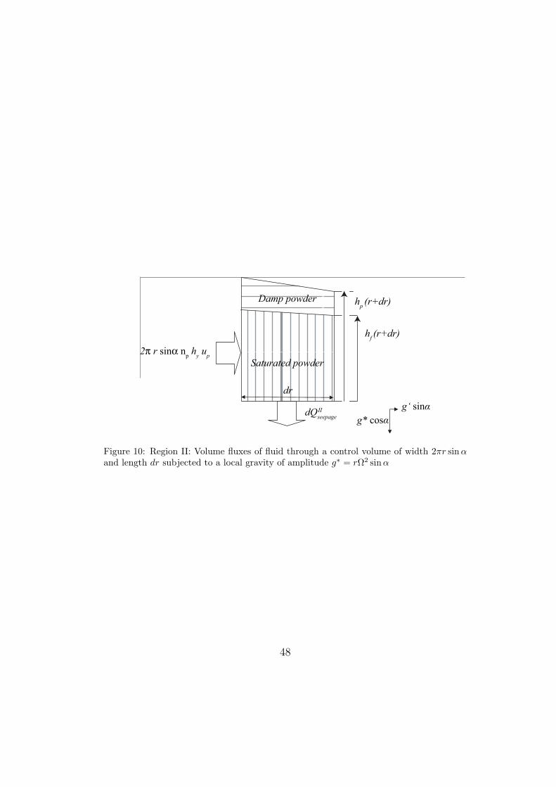
7.2.2. Region II
Consider volume conservation in the circular element of radial width dr
and perimeter 2πr sinα located at a radial coordinate r shown in Fig.10.
The liquid flow rate out of the element of width dr at the coordinate r
shown in Fig.10 is
dQIIseep =
2πρfkprg∗ cosα sinα
µf
dr (74)
and transport of fluid via the radial displacement of densely packed powder
leads to the following convective volumetric flow rate:
QIIconv(r) = 2πnprh
IIf uII
p sinα (75)
Fluid conservation in the element of the saturated layer shown in Fig.10 then
yields the ODEd
dr[QII
conv] +dQII
seep
dr= 0 (76)
We express the fluid conservation equation (76) in a dimensionless form via
(60), (74-75)dHII
f
dR= − RZ
npU IIp
−HII
f (R)
R(77)
and upon taking the initial condition for region II as
HIIf (RS=1) = HII
p (RS=1) (78)
32

we obtain the fluid thickness profile in region II
HIIf (R) =
1
npU IIp R
((ln[np(Sin − 1) + 1] + np) +
Z
3(1−R3)
)(79)
The radial coordinate at which the fluid thickness vanishes RS=0 is obtained
from (79)
RS=0 ≡rS=0
rin=
(1 +
3
Z(ln[np(Sin − 1) + 1] + np)
)1/3
(80)
7.3. Accuracy of simplified model
This simplified model introduces a discontinuity in velocity (and therefore
also cake thickness) at R = RS=1 and R = RS=0 due to the discontinuity in
saturation S assumed to obtain the flow velocity (64). However, numerical
results show that its prediction for the value of RS=0 is close to that of the
more complete model developed in Bizard and Symons (2011) for a typical
sucrose machine (Tables 1-3). In Fig.11 the fluid and cake thickness profiles
given by the simplified model are plotted (thick lines) together with the
results of the complete model (thin lines). Because the simple model does
not allow any internal shear of the flow it overestimates the initial fluid and
cake thicknesses. On the other hand the simple model also neglects any
resistance of the screen to drainage and the fluid level Hf descends more
steeply. These two simplifications therefore almost offset each other in terms
of prediction of the desaturation point location.
Values of RS=0 predicted by the simple model presented in this paper
and the more complete model of Bizard and Symons (2011) are compared in
Fig.12. Contours of RS=0 are plotted for a range of values of seepage number
Z, screen permeability κ and relative density ρ (for constant Min and np and
33
hence varying Sin, see (25)). κ is the ratio of the screen permeability to the
densely packed powder as defined by Bizard and Symons (2011). When κ
exceeds 10−1 the value of RS=0 lies close to that predicted by the complete
model of Bizard and Symons (2011) over a wide range of Z and ρ.
References
Barr, J.D. and White, L.R. (2006), ‘Centrifugal drum filtration: I. A com-
pression rheology model of cake formation’, American Institute of Chemical
Engineers Journal . 52(2), 545–556.
Bizard, A. F. M., Symons, D. D., Fleck, N. A. and Durban, D. (2011),
‘Flow of damp powder in a rotating impervious cone’, Journal of Applied
Mechanics 78, 021017-1-10.
Bizard, A.F.M. and Symons, D.D. (2011), ‘Flow of wet powder in a conical
centrifugal filter - an analytical model’, Chemical Engineering Science .
66, 6014–6027.
Bruin, S. (1969), ‘Velocity distributions in a liquid film flowing over a rotating
conical surface’, Chemical Engineering Science 24(11), 1647–1654.
Carman, P. C. (1956), Flow of Gases through Porous Media, (Butterworths
Scientific Publications, London, UK)
Darcy, H. (1856), ‘Determination des lois d’ecoulement de l’eau a travers le
sable’, Les Fontaines Publiques de la Ville de Dijon .
34

Dombrowski, H.S. and Brownell, L.E. (1954), ‘Residual equilibrium satura-
tion of porous media’, Industrial and Engineering Chemistry 46(6), 1207–
1219.
Greig, C. (1995), ‘Phd thesis: Studies on continuous sugar centrifuges’, De-
partment of chemical engineering, University of Queensland .
Grimwood, C. (2000), ‘Chapter 14 - Centrifugation’ in Handbook of Sugar
Refining, Chi Chou, C. (ed), (Wiley, New York, USA), pp 203–244
Grimwood, C. (2005), ’Chapter 7 - Filtering centrifuges’ in Solid/Liquid Sep-
aration - Scale-up of Industrial Equipment, Wakeman, R.J. and Tarleton,
S. (eds), (Elsevier, UK). pp 314–374
Grimwood, G. and Ferrier, C. (1972), ‘Discharge of solid particles from cen-
trifugal machine’, United States Patent and Trademark Office (04/876229).
Leung, W. W.-F. (1998), Industrial centrifugation technology, McGraw-Hill,
New York.
Makarytchev, S. V., Langrish, T. A. G. and Prince, R. G. H. (1998), ‘Struc-
ture and regimes of liquid film flow in spinning cone columns’, Chemical
Engineering Science 53(8), 1541–1550.
Makarytchev, S. V., Xue, E., Langrish, T. A. G. and Prince, R. G. H. (1997),
‘On modelling fluid flow over a rotating conical surface’, Chemical Engi-
neering Science 52(6), 1055–1057.
Norbury, R.J. and White, E.T. (1973), Preliminary studies on the breakage
35

of sugar crystals on impact, Proc. of the 40th Conference of the Queensland
Society of Sugar Cane Technologists, 171–179.
Roark, R. J. and Young, W. C. (1989), Roark’s formulas for stress and strain,
6th edn, McGraw-Hill, New York.
Soltani, F. and Yilmazer, U. (1998), ‘Slip velocity and slip layer thickness
in flow of concentrated suspensions’, Journal of Applied Polymer Science
70(3), 515–522.
Swindells, R. (1982), ‘Phd thesis: A mathematical model of a continu-
ous sugar centrifuge’, Department of chemical engineering, University of
Queensland .
Swindells, R. J. and White, E. T. (1980), ‘Breakage of sugar crystals on
impact’, Sugar Journal 43(2), 23–25.
Symons, D. D. (2011a), ‘Frictional flow of damp granular material in a conical
centrifuge’, Proc. IMechE Part C: J. of Mechanical Engineering Science.
226, 1055–1057.
Symons, D. D. (2011b), ‘Integral methods for flow in a conical centrifuge’,
Chemical Engineering Science 66(13), 94–103.
Terzaghi, K. (1943), Theoretical soil mechanics, J. Wiley and Sons. New
York.
Yilmazer, U. and Kalyon, D.M. (1989), ‘Slip effects in capillary and paral-
lel disk torsional flows of highly filled suspensions’, Journal of Rheology
33, 1197–1212.
36

Wakeman, R. (1977), ‘Dewatering properties of particulate beds’, Journal of
Powder and Bulk Solids Technology pp. 64–69.
Wakeman, R. J. and Tarleton, E. S. (1999), Filtration : Equipment selection,
modelling and process simulation, Elsevier Science Ltd.
[Figure 1 about here.]
[Figure 2 about here.]
[Figure 3 about here.]
[Figure 4 about here.]
[Figure 5 about here.]
[Figure 6 about here.]
[Figure 7 about here.]
[Figure 8 about here.]
[Figure 9 about here.]
[Figure 10 about here.]
[Figure 11 about here.]
[Figure 12 about here.]
[Table 1 about here.]
[Table 2 about here.]
[Table 3 about here.]
37

List of Figures
1 Section of a typical continuous centrifugal filter . . . . . . . . 392 (a) Flow in a rotating perforated cone and (b) microstructure
and velocity profile of the solid/liquid/air phases in regionsI, II and III for the simple situation where all powder hassedimented before inlet . . . . . . . . . . . . . . . . . . . . . . 40
3 Model geometry . . . . . . . . . . . . . . . . . . . . . . . . . . 414 Residual saturation against capillary number (from Wakeman
(1977)) . . . . . . . . . . . . . . . . . . . . . . . . . . . . . . . 425 Range of possible basket sizes and spinning velocities for su-
crose massecuite with an input powder volumeteric flow rateQp = 2.9× 10⁻³m3/s . . . . . . . . . . . . . . . . . . . . . . . 43
6 Sucrose massecuite: (a) Construction of the design zone Σ fortwo different values of Qp (b) Evolution of Σ as Qp increases . 44
7 Sucrose massecuite: Envelope design domain, independent ofQp . . . . . . . . . . . . . . . . . . . . . . . . . . . . . . . . . 45
8 Microstructure considered in regions I and II for (a) equilib-rium and (b) fluid conservation . . . . . . . . . . . . . . . . . 46
9 Region I: Volume fluxes of fluid through a control volume ofwidth 2πr sinα and length dr subjected to a local gravity ofamplitude g∗ = rΩ2 sinα . . . . . . . . . . . . . . . . . . . . . 47
10 Region II: Volume fluxes of fluid through a control volume ofwidth 2πr sinα and length dr subjected to a local gravity ofamplitude g∗ = rΩ2 sinα . . . . . . . . . . . . . . . . . . . . . 48
11 Comparison between the thickness profiles predicted by thecomplete flow model (thin lines) and the simplified model(thick lines) for typical values of a sucrose centrifuge . . . . . 49
12 Comparison between the position of the desaturation pointpredicted by the complete flow model (solid lines) and thesimplified model (dashed lines) for typical values of a sucrosecentrifuge. The working point of the typical sucrose centrifugeconsidered earlier is marked with a black square . . . . . . . . 50
38

Drained
fluid
Upper
perforated
cone
Lower
imperforate
cone
Input
slurry
15º
30º
1m
1m
Output powder
Figure 1: Section of a typical continuous centrifugal filter
39
(b)
Filtrate
discharge
Filter screen
Mot
ion
of c
ryst
als
Rotation axis
III
II
I
(a)
III
vup
hp
0
II
vup
hp
hf
0
I
v0 u
p
hp
hf
z
Figure 2: (a) Flow in a rotating perforated cone and (b) microstructure and velocityprofile of the solid/liquid/air phases in regions I, II and III for the simple situation whereall powder has sedimented before inlet
40
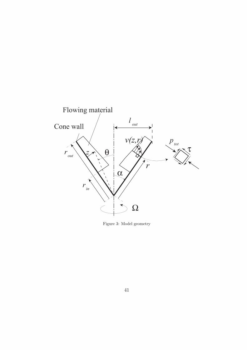
r
v(z,r)
z
rin
rout
Flowing material
Cone wall
ptot
lout
Figure 3: Model geometry
41

Ncap
S∞
10−3
10−2
10−1
1
10−5
10−4
10−3
10−2
10−1
1 10
Figure 4: Residual saturation against capillary number (from Wakeman (1977))
42

lout (m)
Σ(Qp)
10
102
103
104
105
106
10−4 10−3 10−2 10−1 1 10 102
Ω (s−1)
Typical sugar machine
a
bc
X1(Qp) = C1
X2(Qp) = C2
X3 = C3
X4 = C4
vout =cst
g∗out =cst
Figure 5: Range of possible basket sizes and spinning velocities for sucrose massecuitewith an input powder volumeteric flow rate Qp = 2.9× 10⁻³m3/s
43

lout (m)
(a)
Σ(Qp)
X1(Qp) = C1
X2(Qp) = C2
10
102
103
104
105
106
10−4 10−3 10−2 10−1 1 10 102
Qp = 8× 10⁻⁷m3/s
Qp = 4× 10⁻⁴m3/s
Ω (s−1)
lout (m)
(b)
10
102
103
104
105
106
10−4 10−3 10−2 10−1 1 10 102
Σ(Qminp )
Σ(Qoptp )
Σ(Qmaxp )increasing Qp
Ω (s−1)
Figure 6: Sucrose massecuite: (a) Construction of the design zone Σ for two differentvalues of Qp (b) Evolution of Σ as Qp increases
44

lout (m)
Σ(Qoptp )
10
102
103
104
105
106
10−4 10−3 10−2 10−1 1 10 102
g∗out = gmaxout
g∗out = gdry
vout = vminout
vout = vbkf
Ω (s−1)
lminout
Figure 7: Sucrose massecuite: Envelope design domain, independent of Qp
45

II
(a)
(b)
I
up
II
v
hp
hp/2
0
v
0
hp
z
up
I
up
II
v
hp
hf
0
v
0
hp
hf
z
up
I
Figure 8: Microstructure considered in regions I and II for (a) equilibrium and (b) fluidconservation
46

2π r sinα ( hf - h
p ) u
p
dr
dQseepage
Pure fluid
Saturated powder2π r sinα np h
p u
p
hf (r+dr)
hp (r+dr)
g* sinα
g* cosαI
Figure 9: Region I: Volume fluxes of fluid through a control volume of width 2πr sinα andlength dr subjected to a local gravity of amplitude g∗ = rΩ2 sinα
47
dr
g‘ sinα
g* cosα
Damp powder
Saturated powder
2π r sinα np h
y u
p
hp (r+dr)
hf (r+dr)
dQseepage
II
Figure 10: Region II: Volume fluxes of fluid through a control volume of width 2πr sinαand length dr subjected to a local gravity of amplitude g∗ = rΩ2 sinα
48

0
0.2
0.4
0.6
0.8
1
1 1.2 1.4 1.6 1.8 2 2.2
H
(full model)
R
HfHp
RS=1
RS=1
RS=0
RS=0 (simple model)
Figure 11: Comparison between the thickness profiles predicted by the complete flowmodel (thin lines) and the simplified model (thick lines) for typical values of a sucrosecentrifuge
49

κ
(a )
10− 1
1
10
10− 2 10− 1 1 10
Z
1.2
1.2
1.5
1.5
2
2
3
4
Simple model
Full model
ρ
(b)
Z
10− 1
1
10
2 3 4 5 6 7 8 9 10
1.1
1.11.2
1.2
1.5
1.5
2
2
Full model
Simple model
Figure 12: Comparison between the position of the desaturation point predicted by thecomplete flow model (solid lines) and the simplified model (dashed lines) for typical valuesof a sucrose centrifuge. The working point of the typical sucrose centrifuge consideredearlier is marked with a black square
50
List of Tables
1 Parameters considered for a typical sucrose centrifuge . . . . . 522 Dimensionless parameters for the typical sucrose centrifuge
described in Table 1 . . . . . . . . . . . . . . . . . . . . . . . 533 Design targets for a typical sucrose centrifuge . . . . . . . . . 54
51

Conerin (m) rout (m) Ω (rad s−1) α () ρb (kg m−3) σy (MPa)0.54 1.185 188.5 30 7800 600
Input slurrym (kg s−1) Min (%)
5.6 50
Powderρp (kg m−3) dp (µm) np (%) b kp (m2)
1580 500 40 0.5 5×10⁻¹⁰
Fluidρf (kg m−3) µf (Pa s) γ (mN m−1)
1400 1 50
Table 1: Parameters considered for a typical sucrose centrifuge
52

Rout b Z κ ρ Ro(rout) Bo(rout)
2.2 0.87 1.8 0.18 1.1 0.0013 128
Table 2: Dimensionless parameters for the typical sucrose centrifuge described in Table 1
53
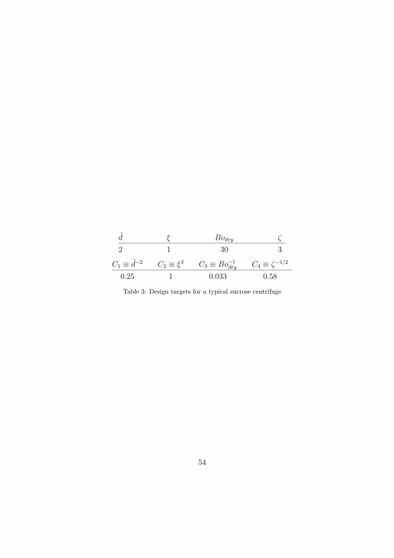
d ξ Bodry ζ
2 1 30 3
C1 ≡ d−2 C2 ≡ ξ3 C3 ≡ Bo−1dry C4 ≡ ζ−1/2
0.25 1 0.033 0.58
Table 3: Design targets for a typical sucrose centrifuge
54