design guide for cisco unity connection - iwan · pdf filedesign guide for cisco unity...
TRANSCRIPT

Design Guide for Cisco Unity ConnectionRelease 7.x Revised July 9, 2009
Americas HeadquartersCisco Systems, Inc.170 West Tasman DriveSan Jose, CA 95134-1706 USAhttp://www.cisco.comTel: 408 526-4000
800 553-NETS (6387)Fax: 408 527-0883
Text Part Number: OL-18210-01

THE SPECIFICATIONS AND INFORMATION REGARDING THE PRODUCTS IN THIS MANUAL ARE SUBJECT TO CHANGE WITHOUT NOTICE. ALL STATEMENTS, INFORMATION, AND RECOMMENDATIONS IN THIS MANUAL ARE BELIEVED TO BE ACCURATE BUT ARE PRESENTED WITHOUT WARRANTY OF ANY KIND, EXPRESS OR IMPLIED. USERS MUST TAKE FULL RESPONSIBILITY FOR THEIR APPLICATION OF ANY PRODUCTS.
THE SOFTWARE LICENSE AND LIMITED WARRANTY FOR THE ACCOMPANYING PRODUCT ARE SET FORTH IN THE INFORMATION PACKET THAT SHIPPED WITH THE PRODUCT AND ARE INCORPORATED HEREIN BY THIS REFERENCE. IF YOU ARE UNABLE TO LOCATE THE SOFTWARE LICENSE OR LIMITED WARRANTY, CONTACT YOUR CISCO REPRESENTATIVE FOR A COPY.
The Cisco implementation of TCP header compression is an adaptation of a program developed by the University of California, Berkeley (UCB) as part of UCB’s public domain version of the UNIX operating system. All rights reserved. Copyright © 1981, Regents of the University of California.
NOTWITHSTANDING ANY OTHER WARRANTY HEREIN, ALL DOCUMENT FILES AND SOFTWARE OF THESE SUPPLIERS ARE PROVIDED “AS IS” WITH ALL FAULTS. CISCO AND THE ABOVE-NAMED SUPPLIERS DISCLAIM ALL WARRANTIES, EXPRESSED OR IMPLIED, INCLUDING, WITHOUT LIMITATION, THOSE OF MERCHANTABILITY, FITNESS FOR A PARTICULAR PURPOSE AND NONINFRINGEMENT OR ARISING FROM A COURSE OF DEALING, USAGE, OR TRADE PRACTICE.
IN NO EVENT SHALL CISCO OR ITS SUPPLIERS BE LIABLE FOR ANY INDIRECT, SPECIAL, CONSEQUENTIAL, OR INCIDENTAL DAMAGES, INCLUDING, WITHOUT LIMITATION, LOST PROFITS OR LOSS OR DAMAGE TO DATA ARISING OUT OF THE USE OR INABILITY TO USE THIS MANUAL, EVEN IF CISCO OR ITS SUPPLIERS HAVE BEEN ADVISED OF THE POSSIBILITY OF SUCH DAMAGES.
CCDE, CCSI, CCENT, Cisco Eos, Cisco HealthPresence, the Cisco logo, Cisco Lumin, Cisco Nexus, Cisco Nurse Connect, Cisco Stackpower, Cisco StadiumVision, Cisco TelePresence, Cisco WebEx, DCE, and Welcome to the Human Network are trademarks; Changing the Way We Work, Live, Play, and Learn and Cisco Store are service marks; and Access Registrar, Aironet, AsyncOS, Bringing the Meeting To You, Catalyst, CCDA, CCDP, CCIE, CCIP, CCNA, CCNP, CCSP, CCVP, Cisco, the Cisco Certified Internetwork Expert logo, Cisco IOS, Cisco Press, Cisco Systems, Cisco Systems Capital, the Cisco Systems logo, Cisco Unity, Collaboration Without Limitation, EtherFast, EtherSwitch, Event Center, Fast Step, Follow Me Browsing, FormShare, GigaDrive, HomeLink, Internet Quotient, IOS, iPhone, iQuick Study, IronPort, the IronPort logo, LightStream, Linksys, MediaTone, MeetingPlace, MeetingPlace Chime Sound, MGX, Networkers, Networking Academy, Network Registrar, PCNow, PIX, PowerPanels, ProConnect, ScriptShare, SenderBase, SMARTnet, Spectrum Expert, StackWise, The Fastest Way to Increase Your Internet Quotient, TransPath, WebEx, and the WebEx logo are registered trademarks of Cisco Systems, Inc. and/or its affiliates in the United States and certain other countries.
All other trademarks mentioned in this document or website are the property of their respective owners. The use of the word partner does not imply a partnership relationship between Cisco and any other company. (0903R)
Any Internet Protocol (IP) addresses used in this document are not intended to be actual addresses. Any examples, command display output, and figures included in the document are shown for illustrative purposes only. Any use of actual IP addresses in illustrative content is unintentional and coincidental.
Design Guide for Cisco Unity Connection Release 7.x © 2009 Cisco Systems, Inc. All rights reserved.
OL-18210-01
C O N T E N T S
Preface ix
Documentation Conventions ix
Cisco Unity Connection Documentation x
Obtaining Documentation and Submitting a Service Request x
Cisco Product Security Overview x
C H A P T E R 1 Cisco Unity Connection Overview 1-1
Flexible User Interface 1-2
Automated Attendant Functionality 1-2
Dial Plan Flexibility: Partitions and Search Spaces 1-3
Languages 1-3
Access to Calendar, Meeting, and Contact Information 1-3
Access to Emails in an External Message Store 1-3
Desktop Message Access 1-3
Mobile Clients 1-4
Fax Messages 1-5
Flexible Administration and Serviceability 1-5
Administrative Tools 1-5
End User Web Tools 1-6
Licensing 1-6
LDAP Directory Synchronization and Authentication 1-6
Security 1-7
Secure Messages 1-7
Securing Communications Between Cisco Unity Connection and Clients 1-8
Migration from Cisco Unity or from Cisco Unity Connection 1.x 1-8
Supported Cisco Unity Connection Servers 1-8
Supported Phone Systems 1-9
Cisco Unity Connection Clusters (Active/Active High Availability and Redundancy) 1-10
Digital Networking 1-10
Third-Party Voicemail Interoperability 1-10
For More Information 1-10
iiiDesign Guide for Cisco Unity Connection Release 7.x

Contents
C H A P T E R 2 Optional Network Resource Requirements 2-1
DHCP 2-1
DNS 2-1
Microsoft Exchange 2-1
LDAP Directory 2-2
C H A P T E R 3 Sizing and Scaling Cisco Unity Connection Servers 3-1
Audio Codecs 3-1
Audio Codec Usage for Call Connections and for Recording 3-1
Audio Codec Considerations for VPIM Networking 3-4
Voice Messaging Ports 3-4
Storage Capacity for Voice Messages 3-5
Users 3-5
Simultaneous TUI/VUI Sessions 3-5
IMAP Clients Used to Access Connection Voice Messages 3-6
Visual Voicemail Clients and Sessions 3-7
Phone View Clients and Sessions 3-7
Simultaneous Mobile Clients 3-7
Cisco Unity Assistant Clients 3-8
Cisco Unity Inbox Clients 3-8
Cisco Unified Personal Communicator Clients 3-8
IBM Lotus Sametime Clients 3-8
RSS Reader Clients 3-9
C H A P T E R 4 Networking 4-1
Digital Networking 4-1
VPIM Networking 4-3
C H A P T E R 5 Migrating to Cisco Unity Connection from Another Voice-Messaging System 5-1
C H A P T E R 6 LDAP Directory Integration with Cisco Unity Connection 6-1
LDAP Synchronization 6-1
Configuring LDAP Synchronization 6-2
Creating Cisco Unity Connection Users 6-5
Filtering LDAP Users 6-5
LDAP Authentication 6-6
ivDesign Guide for Cisco Unity Connection Release 7.x
OL-18210-01

Contents
Configuring LDAP Authentication 6-7
How LDAP Authentication Works 6-7
Additional Considerations for Authentication and Microsoft Active Directory 6-8
C H A P T E R 7 Integrating Cisco Unity Connection with the Phone System 7-1
How a Phone System Integration Works 7-2
Integration with Cisco Unified Communications Manager 7-2
Digital Integration with Digital PIMG Units 7-3
DTMF Integration with Analog PIMG Units 7-3
Serial (SMDI, MCI, or MD-110) Integration with Analog PIMG Units 7-4
TIMG Serial (SMDI, MCI, or MD-110) Integration 7-4
TIMG In-Band Integration 7-5
Settings in the Phone System and in Cisco Unity Connection 7-6
Call Information Exchanged by the Phone System and Cisco Unity Connection 7-6
Call Control 7-7
Sample Path for a Call from the Phone System to a User 7-7
General Integration Issues 7-8
Deploying Phones Across the WAN 7-8
Integrating with Cisco Unified Communications Manager (by Using SCCP or SIP) 7-9
Cisco Unified Communications Manager Authentication and Encryption for Cisco Unity Connection Voice Messaging Ports 7-10
Cisco Unified Communications Manager Security Features 7-10
When Data Is Encrypted 7-13
Cisco Unified Communications Manager Cluster Security Mode Settings in Cisco Unity Connection 7-13
Disabling and Reenabling Security 7-14
Multiple Clusters Can Have Different Security Mode Settings 7-14
Settings for Individual Voice Messaging Ports 7-14
Packetization 7-15
Integrating with Cisco Unified Communications Manager Express (by Using SCCP or SIP) 7-15
Multiple Cisco Unified Communications Manager Express Version Support 7-17
Multiple Cisco Unified Communications Manager Express Routers Integrating with a Single Cisco Unity Connection Server 7-17
Integrating Cisco Unity Connection with Multiple Versions of Cisco Unified Communications Manager and Cisco Unified Communications Manager Express 7-18
Integrating Cisco Unity Connection with Cisco Unified Survivable Remote Site Telephony (Cisco Unified SRST) 7-18
Impact of Non-Delivery of RDNIS on Voice Mail Calls Routed by Using AAR 7-20
Integrating Cisco Unity Connection with Cisco Unified Communications Manager Express in SRST Mode 7-20
vDesign Guide for Cisco Unity Connection Release 7.x
OL-18210-01

Contents
Integrating by Using SIP 7-20
Supported SIP Integrations 7-21
Integrating with Circuit-Switched Phone Systems by Using PIMG or TIMG Units 7-22
Description of PIMG Integrations 7-22
Setup and Configuration 7-22
Firmware Updates 7-23
Serial Integrations 7-23
Increasing Port Capacity 7-23
Cisco Unity Connection Clusters 7-23
Multiple Integration Support/Branch Office Consolidation 7-23
Integrating with Multiple Phone Systems 7-24
Requirements for Integrations with Multiple Phone Systems 7-25
Optional Integration Features 7-25
Alternate Extensions 7-25
Alternate MWIs 7-25
Centralized Voice Messaging 7-25
Integrating Cisco Unity Connection with a QSIG-Enabled Phone System by Using Cisco ISR Voice Gateways 7-27
Links to Additional Integration Information 7-27
C H A P T E R 8 Cisco Unity Connection Clusters (Active/Active High Availability) 8-1
Cisco Unity Connection Cluster Overview 8-1
Publisher Server 8-3
Subscriber Server 8-3
Requirements for Cisco Unity Connection Cisco Unity Connection Cluster 8-3
Support for Installing the Cisco Unity Connection Servers in Separate Buildings or Sites 8-3
Balancing the Load of Calls That the Cisco Unity Connection Servers Handle 8-4
Load Balancing Clients in a Cisco Unity Connection Cluster 8-5
Configuration for Dial-out Voice Messaging Ports 8-5
For More Information 8-6
C H A P T E R 9 Disaster Recovery 9-1
Disaster Recovery 9-1
C H A P T E R 10 Cisco Fax Server Integration 10-1
Cisco Fax Server Overview 10-1
Administration for the Cisco Fax Server 10-1
How Users Manage Fax Messages 10-2
viDesign Guide for Cisco Unity Connection Release 7.x
OL-18210-01

Contents
Single Direct-Inward-Dial (DID) Number Support for Both Voice and Fax 10-3
I N D E X
viiDesign Guide for Cisco Unity Connection Release 7.x
OL-18210-01

Contents
viiiDesign Guide for Cisco Unity Connection Release 7.x
OL-18210-01

Preface
Documentation Conventions
The Design Guide for Cisco Unity Connection also uses the following conventions:
Note Means reader take note. Notes contain helpful suggestions or references to material not covered in the document.
Caution Means reader be careful. In this situation, you might do something that could result in equipment damage or loss of data.
Table 1 Conventions in the Design Guide for Cisco Unity Connection
Convention Description
boldfaced text Boldfaced text is used for:
• Key and button names. (Example: Click OK.)
• Information that you enter. (Example: Enter Administrator in the User Name box.)
< >
(angle brackets)
Angle brackets are used around parameters for which you supply a value. (Example: In your browser, go to https://<Cisco Unity Connection server IP address>/cuadmin.)
-
(hyphen)
Hyphens separate keys that must be pressed simultaneously. (Example: Press Ctrl-Alt-Delete.)
>
(right angle bracket)
A right angle bracket is used to separate selections that you make in the navigation bar of Cisco Unity Connection Administration. (Example: In Cisco Unity Connection Administration, expand Contacts > System Contacts.)
ixDesign Guide for Cisco Unity Connection Release 7.x
OL-18210-01

Preface
Cisco Unity Connection DocumentationFor descriptions and URLs of Cisco Unity Connection documentation on Cisco.com, see the Documentation Guide for Cisco Unity Connection Release 7.x. The document is shipped with Connection and is available at http://www.cisco.com/en/US/docs/voice_ip_comm/connection/7x/roadmap/7xcucdg.html.
Obtaining Documentation and Submitting a Service RequestFor information on obtaining documentation, submitting a service request, and gathering additional information, see the monthly What’s New in Cisco Product Documentation, which also lists all new and revised Cisco technical documentation, at:
http://www.cisco.com/en/US/docs/general/whatsnew/whatsnew.html
Subscribe to the What’s New in Cisco Product Documentation as a Really Simple Syndication (RSS) feed and set content to be delivered directly to your desktop using a reader application. The RSS feeds are a free service and Cisco currently supports RSS Version 2.0.
Cisco Product Security OverviewThis product contains cryptographic features and is subject to United States and local country laws governing import, export, transfer and use. Delivery of Cisco cryptographic products does not imply third-party authority to import, export, distribute or use encryption. Importers, exporters, distributors and users are responsible for compliance with U.S. and local country laws. By using this product you agree to comply with applicable laws and regulations. If you are unable to comply with U.S. and local laws, return this product immediately.
Further information regarding U.S. export regulations can be found at http://www.access.gpo.gov/bis/ear/ear_data.html.
xDesign Guide for Cisco Unity Connection Release 7.x
OL-18210-01

DOL-18210-01
C H A P T E R 1
Cisco Unity Connection OverviewCisco Unity Connection is a feature-rich voice messaging platform that runs on the same Linux-based Cisco Unified Communications Operating System that is used by Cisco Unified Communications Manager. Connection scales to support enterprise organizations with up to 50,000 users. For organizations with up to 500 users, Connection is available in Cisco Unified Communications Manager Business Edition (CMBE), a single-server solution that includes a co-resident Cisco Unified Communications Manager, which further simplifies installation, support, and maintenance.
Connection includes the following features and components:
End-User Features
• Flexible User Interface, page 1-2
• Automated Attendant Functionality, page 1-2
• Dial Plan Flexibility: Partitions and Search Spaces, page 1-3
• Languages, page 1-3
• Access to Calendar, Meeting, and Contact Information, page 1-3
• Access to Emails in an External Message Store, page 1-3
• Desktop Message Access, page 1-3
• Mobile Clients, page 1-4
• Fax Messages, page 1-5
System Administration
• Flexible Administration and Serviceability, page 1-5
• Licensing, page 1-6
• LDAP Directory Synchronization and Authentication, page 1-6
• Security, page 1-7
• Migration from Cisco Unity or from Cisco Unity Connection 1.x, page 1-8
Supported Servers and Phone Systems
• Supported Cisco Unity Connection Servers, page 1-8
• Supported Phone Systems, page 1-9
Enterprise Features
• Cisco Unity Connection Clusters (Active/Active High Availability and Redundancy), page 1-10
1-1esign Guide for Cisco Unity Connection Release 7.x

Chapter 1 Cisco Unity Connection Overview Flexible User Interface
• Digital Networking, page 1-10
• Third-Party Voicemail Interoperability, page 1-10
For links to additional related documentation on Cisco.com, see the “For More Information” section on page 1-10.
Flexible User InterfaceThere are two ways in which users can interact with Cisco Unity Connection by phone:
• Phone keypad keys—Users press keys on any touchtone phone to respond to prompts or select menu options.
• Voice commands—Users speak into the phone handset, headset, or speakerphone, and Connection responds to their voice commands. Users have the option to press keys on the phone keypad for a primary set of commands rather than say a voice command.
The Connection conversations can be customized both by administrators and by end users to maximize company and individual productivity. Users can configure the system to manage calls and messages in the way that is most comfortable and convenient for them, which makes messaging more efficient for “power users” and occasional voicemail users alike. In addition, for users who are accustomed to third-party voicemail conversations, Connection offers multiple conversation keypad mappings that can be further customized, as well as the option to create a new conversation by using the Custom Keypad Mapping tool.
To maximize the productivity of mobile workers, consider enabling the speech-activated voice command interface. This interface allows users to browse and manage voice messages and to call other Connection users or personal contacts by using simple, natural speech commands.
The phone interface also allows for access to Microsoft Exchange calendars, contacts, and emails, and to Cisco Unified MeetingPlace and Cisco Unified MeetingPlace Express meetings.
Automated Attendant FunctionalityCisco Unity Connection includes a full-featured automated attendant that is customizable to suit the needs of your organization. Connection provides a number of different call management elements that you can combine to customize how your system handles calls and collects input from callers. You can use the default configuration to play a company greeting to callers, allow them to enter user extensions or reach a directory of users, or reach an operator. Or, you can add and customize additional elements to create complex audio-text trees that can ask callers a series of questions and record their responses, offer tiered menus of product information, route calls to a support queue during working hours and to a mailbox after hours, immediately play legal disclaimers or “snow day” recordings to all callers before allowing them to interact with the system, and so on.
For information on call management in Cisco Unity Connection and the various elements that make up the Connection conversation such as call handlers, directory handlers, interview handlers, call routing tables, schedules and holidays, and restriction tables, see the System Administration Guide for Cisco Unity Connection Release 7.x. Also in that guide is information on creating a call management plan, how outside callers and users interact with the Connection conversation, and how administrators and users can customize the Connection conversation. The guide is available at http://www.cisco.com/en/US/docs/voice_ip_comm/connection/7x/administration/guide/7xcucsagx.html.
1-2Design Guide for Cisco Unity Connection Release 7.x
OL-18210-01

Chapter 1 Cisco Unity Connection Overview Dial Plan Flexibility: Partitions and Search Spaces
Dial Plan Flexibility: Partitions and Search SpacesDial plan flexibility is supported through the use of partitions and search spaces, with which you can segment the Cisco Unity Connection directory for both dialing and addressing. For example, partitions and search spaces can be configured to allow for overlapping extensions, abbreviated dialing, or multi-tenant configurations.
For more information on using partitions and search spaces, see the “Managing Partitions and Search Spaces” chapter of the System Administration Guide for Cisco Unity Connection Release 7.x.
LanguagesWhen multiple languages are installed, you can configure the language for system prompts that are played to users and callers. Separate greetings can be recorded for users and call handlers in each language that is installed on the system. Routing rules can be configured to set the language for a call based on how the call reached the system.
For a list of supported languages, see the “Available Languages for Cisco Unity Connection Components” section of System Requirements for Cisco Unity Connection Release 7.x at http://www.cisco.com/en/US/docs/voice_ip_comm/connection/7x/requirements/7xcucsysreqs.html.
Access to Calendar, Meeting, and Contact InformationWhen Cisco Unity Connection is configured for a calendar integration, users can access calendar and meeting information from Cisco Unified MeetingPlace, Cisco Unified MeetingPlace Express, and Microsoft Exchange, and can import Exchange contacts for use by rules created in the Personal Call Transfer Rules web tool and for use by voice commands when placing outgoing calls.
For more information, see the “Creating Calendar Integrations” chapter of the System Administration Guide for Cisco Unity Connection Release 7.x.
Access to Emails in an External Message StoreWhen Cisco Unity Connection is configured to connect to an external message store (a message store other than Connection), users can hear their emails read to them by the Text to Speech (TTS) feature when they log on to Connection by phone. For more information, see the “Configuring Access to Emails in an External Message Store” chapter of the System Administration Guide for Cisco Unity Connection Release 7.x.
Desktop Message AccessCisco Unity Connection supports access to voice messages through a wide range of desktop clients, including:
• IMAP clients—Third-party IMAP clients such as email clients are supported for accessing voice messages from Connection. Users can read, reply to, and forward messages from these types of clients. For more information, see the “Configuring IMAP Settings” chapter of the System Administration Guide for Cisco Unity Connection Release 7.x.
1-3Design Guide for Cisco Unity Connection Release 7.x
OL-18210-01

Chapter 1 Cisco Unity Connection Overview Mobile Clients
• Cisco Unity Connection ViewMail for Microsoft Outlook plug-in—In addition to basic IMAP access to Cisco Unity Connection voice messages, the Cisco Unity Connection ViewMail for Microsoft Outlook form allows playing and recording messages by using either the phone or workstation speakers and microphones. Users can compose, read, reply to, and forward messages when using ViewMail. For more information on the ViewMail for Outlook client, see the User Guide for Accessing Cisco Unity Connection Voice Messages in an E-Mail Application at http://www.cisco.com/en/US/docs/voice_ip_comm/connection/7x/user/guide/email/7xcucugemailx.html, and the “Configuring Cisco Unity Connection ViewMail for Microsoft Outlook” section in the “Configuring an Email Account to Access Cisco Unity Connection Voice Messages” chapter of the User Workstation Setup Guide for Cisco Unity Connection Release 7.x.
• Cisco Unity Inbox—The Cisco Unity Inbox is a web tool available on the Cisco Personal Communications Assistant (PCA) website. Users can compose, read, reply to, and forward messages from the Cisco Unity Inbox. For more information, see the User Guide for the Cisco Unity Connection Inbox Web Tool at http://www.cisco.com/en/US/docs/voice_ip_comm/connection/7x/user/guide/inbox/7xcucuginboxx.html.
• Cisco Unified Personal Communicator—Cisco Unified Personal Communicator is a desktop client that allows users to play voice messages. Users can read and delete messages from Cisco Unified Personal Communicator. For more information, see the CUPC product pages at http://www.cisco.com/en/US/products/ps6844/tsd_products_support_series_home.html.
• Cisco Unified Messaging with IBM Lotus Sametime—Cisco Unified Messaging with IBM Lotus Sametime integrates Connection voicemail into the IBM Lotus Sametime instant messaging application, allowing users to play their voice messages within Lotus Sametime. A list of all voice messages, including the caller name or number and the date and time, are displayed in a panel on the client window. Users simply click to play their voice messages. They can also sort and delete messages directly from the Lotus Sametime application. For more information, see the Release Notes for Cisco Unified Messaging with IBM Lotus Sametime at http://www.cisco.com/en/US/products/ps6509/prod_release_notes_list.html.
• Cisco Phone View—Cisco Unity Connection Phone View allows users to display voice messages on the LCD screen of a Cisco IP phone and to play the voice messages. This feature uses either touchtone keys or voice commands. The criteria that you use to search for messages depends on the conversation version that you are using. For information on setting up Phone View, see the “Setting Up Phone View” chapter of the System Administration Guide for Cisco Unity Connection Release 7.x.
• RSS Feeds—As an alternative to checking messages by phone or by using the Cisco Unity Inbox or an IMAP client, users can retrieve voice messages by using an RSS (Really Simple Syndication) reader. When a user marks a message as read, the message is no longer displayed in the RSS reader, but a saved copy is available in the Connection mailbox of the user. For more information on configuring Cisco Unity Connection to supply RSS feeds, see the “Configuring Access to RSS Feeds of Voice Messages” section in the “Messaging” chapter of the System Administration Guide for Cisco Unity Connection Release 7.x.
Mobile ClientsCisco Unity Connection supports access to voice messages from Windows mobile phones, RIM BlackBerry devices, and Symbian OS phones through Cisco Unified Mobility Advantage and Cisco Unified Mobile Communicator.
1-4Design Guide for Cisco Unity Connection Release 7.x
OL-18210-01

Chapter 1 Cisco Unity Connection Overview Fax Messages
For a list of supported mobile clients with Connection Release 7.x with the Cisco Unified Mobile Advantage Release 7.0 and Cisco Unified Mobile Communication Release 3.x and 7.0, see the Compatibility Matrix for Cisco Unified Mobility Advantage and Cisco Unified Mobile Communicator, available at http://www.cisco.com/en/US/products/ps7271/products_device_support_tables_list.html.
Fax MessagesCisco Unity Connection can integrate with Cisco Fax Server 9.0 or later to support fax messages. Users can send a fax to a fax machine for printing (users can specify the fax number by phone), download a fax from a supported IMAP client, and forward fax messages to other Connection users. For more information, see the “Cisco Fax Server Integration” chapter.
Flexible Administration and ServiceabilitySee the following sections:
• Administrative Tools, page 1-5
• End User Web Tools, page 1-6
Administrative ToolsCisco Unity Connection provides a set of tools for administrating, monitoring, and troubleshooting the system. These tools, some of which are also used by Cisco Unified Communications Manager, are designed to offer a consistent experience and to streamline the ongoing management and operation of the system.
• Cisco Unified Serviceability—A monitoring and troubleshooting tool for serviceability that is shared with Cisco Unified Communications Manager. This tool allows you generate reports, enable alarms, set trace information, activate or deactivate services that are generic to the platform, and configure simple network management protocol (SNMP) operations.
• Cisco Unity Connection Serviceability—A monitoring and troubleshooting tool for serviceability that is used only by Connection. This tool allows you generate reports, enable alarms, set trace information, manage a Connection cluster, and activate or deactivate services that are specific to Connection.
• Real-Time Monitoring Tool—A tool that runs as a client-side application. This tool can monitor system performance, view system error messages, and collect trace log files.
• Cisco Unified OS Administration—A tool that you can use to change operating system settings (for example, IP address or NTP servers), view hardware and software configuration information (for example, the amount of memory or the Cisco Unified Communications Operating System version), manage SSL certificates, upgrade Connection and the operating system (they are upgraded together), and enable remote access to the Connection server.
• Cisco Unity Connection Administration—A tool used for most administrative tasks, including specifying settings for users and implementing a call management plan. Connection Administration provides access to several other tools including the Bulk Administration Tool, Bulk Edit Utility, Custom Keypad Mapping, Task Management, and tools for importing and migrating user accounts.
• Disaster Recovery System—A tool that allows you to back up and, if necessary, restore data and voice messages. For more information, see the “Disaster Recovery” chapter.
1-5Design Guide for Cisco Unity Connection Release 7.x
OL-18210-01

Chapter 1 Cisco Unity Connection Overview Licensing
For more information about all of the administrative tools, see the “Administrative Tools” chapter of the System Administration Guide for Cisco Unity Connection Release 7.x.
Connection also allows administration tasks to be segmented by administrator roles, so that administrators can be given permission to perform a range of operations from doing individual tasks (for example, resetting passwords or unlocking accounts) to doing all Connection administration functions. For more information, see the “Roles” section in the “Preparing to Add User Accounts” chapter of the User Moves, Adds, and Changes Guide for Cisco Unity Connection Release 7.x.
End User Web ToolsWhen end users are given access to the browser-based Cisco Personal Communications Assistant (PCA), they can also be granted access to the following web tools:
• Cisco Unity Assistant—Allows users to quickly and easily change personal settings such as voicemail options, passwords, personal distribution lists, and message-delivery options.
• Cisco Unity Personal Call Transfer Rules—Allows users to create call transfer rules that forward and screen incoming calls based on caller, time of day, or calendar status. (Personal Call Transfer Rules are supported only when Cisco Unity Connection is integrated with Cisco Unified Communications Manager phone systems.)
• Cisco Unity Inbox—Allows users to send and access voice messages.
To learn more about these tools, see the applicable User Guide for Cisco Unity Connection Release 7.x and the Help for each tool. Cisco Unity Connection user guides are available at http://www.cisco.com/en/US/products/ps6509/products_user_guide_list.html.
LicensingCisco Unity Connection uses license files to enable licensed features. To use a licensed feature, the customer must purchase the applicable license file. A valid Connection license file is required to configure a new Connection system and for adding or changing licensed features. Each license file that a customer purchases uses the MAC address for the network interface card (NIC) in the Connection server, so the license file can be installed only on the server with that MAC address. For information on Connection licenses, see the “Managing Licenses” chapter of the System Administration Guide for Cisco Unity Connection Release 7.x.
LDAP Directory Synchronization and AuthenticationIf you are using a supported LDAP directory for your corporate directory, Cisco Unity Connection gives you the option to synchronize a small subset of user data in the Connection database with user data in the LDAP directory. In addition, if you configure directory synchronization, you can have Connection authenticate user access to Connection web applications against Active Directory credentials. You can also configure Connection to periodically resynchronize Connection user data with user data in the LDAP directory.
Connection LDAP directory support does not require directory schema extensions, and access to the directory is read-only.
1-6Design Guide for Cisco Unity Connection Release 7.x
OL-18210-01

Chapter 1 Cisco Unity Connection Overview Security
Connection also supports standalone users and users imported from Cisco Unified Communications Manager via AXL. Both standalone users and users imported from Cisco Unified CM can be converted to LDAP users at any time.
For more information on Connection support for LDAP synchronization and authentication, see the “LDAP Directory Integration with Cisco Unity Connection” chapter.
SecurityCisco Unity Connection supports security in a number of areas of the product:
• Platform—Connection is based on the Linux-based Cisco Unified Communications Operating System. The operating system is locked down, and no root access is allowed. For more information on the Cisco Unified Communications Operating System, see the Cisco Unified Communications Operating System Administration Guide for Cisco Unity Connection Release 7.x at http://www.cisco.com/en/US/docs/voice_ip_comm/connection/7x/os_administration/guide/7xcucosagx.html.
• Call signaling and media stream—Connection allows for authentication and encryption of call signaling and media with both SCCP and SIP trunk integrations with Cisco Unified Communications Manager. For more information, see the “Integrating Cisco Unity Connection with the Phone System” chapter.
• Unauthorized access—In order to help prevent unauthorized access, Connection allows for authentication polices (for both phone and web access) that can control the number of attempted logons, account lockout policies, minimum password lengths, and password expiration. For more information, see the “Specifying Password, Logon, and Lockout Policies” chapter of the System Administration Guide for Cisco Unity Connection Release 7.x.
• Unauthorized transfers and dial outs—Connection restriction tables control which numbers are allowed for transfers and dialouts, thus locking down unauthorized use of the system by users and helping prevent toll fraud. For more information, see the “Managing Restriction Tables” chapter of the System Administration Guide for Cisco Unity Connection Release 7.x.
• Secure messages—Connection supports secure messaging. For more information, see the following “Secure Messages” section.
• Communications between Cisco Unity Connection and clients—For more information on securing the communications between Connection and clients, see the “Securing Communications Between Cisco Unity Connection and Clients” section on page 1-8.
Secure MessagesMessages that are marked secure are stored only on the Cisco Unity Connection server, thereby disallowing secure messages from leaving an organization. Users cannot make local copies of secure messages. Message aging policies allow administrators to control how long secure messages are retained before they are archived or permanently deleted.
Secure messages can be played only by using the following interfaces:
• Phone
• Cisco Unity Inbox
• Cisco Unity Connection ViewMail for Microsoft Outlook
• Cisco Unified Personal Communicator (CUPC)
1-7Design Guide for Cisco Unity Connection Release 7.x
OL-18210-01

Chapter 1 Cisco Unity Connection Overview Migration from Cisco Unity or from Cisco Unity Connection 1.x
Secure messages are streamed securely to these interfaces and do not leave the Connection server. When Connection servers are digital networked to communicate with each other, users on one system can send secure messages to users on another. In that situation, secure messages are encrypted with SMIME while they are in transit between servers.
The following interfaces do not support playback of secure messages:
• Third-party IMAP email clients other than Cisco Unity Connection ViewMail for Microsoft Outlook
• IBM Lotus Sametime Plug-in
• RSS Readers
For more information on secure messages, see the “Securing User Messages: Controlling Access and Distribution” chapter of the System Administration Guide for Cisco Unity Connection Release 7.x.
Securing Communications Between Cisco Unity Connection and Clients • Cisco Personal Communications Assistant—For information on securing the Cisco Personal
Communications Assistant (PCA) and Cisco Unity Connection web tools client access to Connection, see the “Securing Cisco PCA and IMAP Email Client Access to Cisco Unity Connection” chapter of the System Administration Guide for Cisco Unity Connection Release 7.x.
• IMAP clients—For information on securing IMAP email client access to Connection, see the “Securing Cisco PCA and IMAP Email Client Access to Cisco Unity Connection” chapter of the System Administration Guide for Cisco Unity Connection Release 7.x and the “Configuring an Email Account to Access Cisco Unity Connection Voice Messages” chapter of the User Workstation Setup Guide for Cisco Unity Connection Release 7.x.
• Mobile clients—For information on securing communication between mobile clients and Cisco Unity Connection, see the Cisco Unified Mobile Communicator and Cisco Unified Mobility Advantage documentation, available at http://www.cisco.com/en/US/products/ps7271/tsd_products_support_series_home.html.
• RSS clients—For information on securing communication between RSS clients and Cisco Unity Connection, see the “Configuring Access to RSS Feeds of Voice Messages” section in the “Messaging” chapter of the System Administration Guide for Cisco Unity Connection Release 7.x.
Migration from Cisco Unity or from Cisco Unity Connection 1.xYou can migrate to Linux-based Cisco Unity Connection 7.x from Windows-based Cisco Unity or Cisco Unity Connection 1.x by using the Cisco Object Backup and Restore Application Suite, COBRAS. The tool ships with Connection 7.x, and you can view training videos and Help on the Cisco Unity Tools website at http://ciscounitytools.com/App_COBRAS.htm. For more information on migration, see the applicable chapter of the Reconfiguration and Upgrade Guide for Cisco Unity Connection 7.x at http://www.cisco.com/en/US/docs/voice_ip_comm/connection/7x/upgrade/guide/7xcucrugx.html.
Supported Cisco Unity Connection ServersFor a list of servers that are qualified for use with Cisco Unity Connection, including detailed hardware specifications, the maximum number of ports, the maximum number of users, the total number of minutes of message storage, and so on, see the Cisco Unity Connection Supported Platforms List at http://www.cisco.com/en/US/products/ps6509/products_data_sheets_list.html.
1-8Design Guide for Cisco Unity Connection Release 7.x
OL-18210-01

Chapter 1 Cisco Unity Connection Overview Supported Phone Systems
Note that when a customer configures a Cisco Unity Connection cluster (active/active high availability), two Connection servers are required:
• The publisher server, which publishes the database and message store.
• The subscriber server, which subscribes to the database and message store on the publisher server.
Note Both servers can service call traffic and client/administration traffic.
Voice Recognition is also supported on the Connection servers. For capacity planning for voice recognition, see the Cisco Unity Connection Supported Platforms List.
Supported Phone SystemsRevised May 2009Cisco Unity Connection natively integrates with Cisco Unified Communications Manager and with Cisco Unified Communications Manager Express through Skinny Client Control Protocol (SCCP) or through a SIP trunk.
If the customer integrates Connection with a circuit-switched phone system, additional hardware is needed:
• Many integrations with circuit-switched phone systems use PIMG or TIMG units for analog, digital, or T1 interfaces. Serial integrations (SMDI, MCI, and MD-110) with analog interfaces also require special cables. For more information about PIMG/TIMG integrations, see the applicable integration guide at http://www.cisco.com/en/US/products/ps6509/products_installation_and_configuration_guides_list.html.
• If the customer integrates Cisco Unity Connection with a QSIG-enabled phone system, an ISR voice gateway is required. For more information, see the applicable integration guide at http://www.cisco.com/en/US/products/ps6509/products_installation_and_configuration_guides_list.html.
Connection can also be integrated with multiple phone systems. For more information, see the Multiple Phone System Integrations Guide for Cisco Unity Connection 7.x at http://www.cisco.com/en/US/docs/voice_ip_comm/connection/7x/integration/misc/guide/cuc7xintmultiple.html.
For the requirements of the phone system integration, see the System Requirements for Cisco Unity Connection Release 7.x at http://www.cisco.com/en/US/docs/voice_ip_comm/connection/7x/requirements/7xcucsysreqs.html.
For more information on phone system integrations, see the “Integrating Cisco Unity Connection with the Phone System” chapter.
For supported deployment models, see the “Cisco Voice Messaging” chapter of the Cisco Unified Communications SRND Based on Cisco Unified Communications Manager 7.x at http://www.cisco.com/en/US/docs/voice_ip_comm/cucm/srnd/7x/vmessage.html.
1-9Design Guide for Cisco Unity Connection Release 7.x
OL-18210-01

Chapter 1 Cisco Unity Connection Overview Cisco Unity Connection Clusters (Active/Active High Availability and Redundancy)
Cisco Unity Connection Clusters (Active/Active High Availability and Redundancy)
Cisco Unity Connection supports a two-server active/active cluster within a site (LAN) to provide high availability and redundancy. Both servers in the Connection cluster run Connection, and both accept calls, HTTP requests, and IMAP requests. If one server in the Connection cluster becomes inactive, the other server continues to provide the end-user functionality including voice calls, HTTP requests, and IMAP requests. In this situation, a lower port capacity will be available for taking voice calls. For more information, see the “Cisco Unity Connection Clusters (Active/Active High Availability)” chapter.
Digital NetworkingRevised July 9, 2009If you have more users than a single Cisco Unity Connection server or cluster pair allows, you can use Digital Networking to internetwork the systems. With Connection 7.0, you can use Digital Networking to connect up to five Connection servers and/or clusters with a combined total of 50,000 users and/or contacts of all types (system contacts with or without an associated VPIM location and personal contacts). With Connection 7.1 and later, you can connect up to ten servers and/or clusters with a combined total of 50,000 users and contacts of all types.
When Digital Networking is used to network together multiple Connection servers or clusters, users can send, reply to, and forward messages or place calls to any user on any Connection server in the Digital Network. A Digital Network can be configured to allow all users to call the same number from outside the organization to log on regardless of which Connection server they are homed on. The system that answers calls to this number transfers users to the applicable home Connection server to log on.
For more information on Digital Networking design, see the “Networking” chapter.
Third-Party Voicemail InteroperabilityCisco Unity Connection supports Voice Profile for Internet Mail (VPIM) version 2, which allows the exchange of voice and text messages with other messaging systems. You can use VPIM Networking to network Connection with up to ten voice messaging systems, including Cisco Unity, Cisco Unity Connection, Cisco Unity Express, or any third-party voice messaging system that supports the VPIM version 2 protocol.
For more information on VPIM Networking design, see the “Networking” chapter.
For More InformationRevised May 2009
System Requirements
The System Requirements for Cisco Unity Connection Release 7.x lists the requirements for installing the Cisco Unity Connection system.
The document is available at http://www.cisco.com/en/US/docs/voice_ip_comm/connection/7x/requirements/7xcucsysreqs.html.
1-10Design Guide for Cisco Unity Connection Release 7.x
OL-18210-01

Chapter 1 Cisco Unity Connection Overview For More Information
Compatibility
The Compatibility Matrix: Cisco Unity Connection and the Software on User Workstations includes the supported version combinations for Cisco Unity Connection and the software installed on user workstations, including browsers and versions supported for each browser when using the Cisco Personal Communications Assistant and Cisco Unity Connection web tools, supported IMAP clients, and information on the versions of Microsoft Outlook that are supported with ViewMail for Outlook.
The SCCP Compatibility Matrix: Cisco Unity Connection, Cisco Unified Communications Manager, and Cisco Unified Communications Manager Express includes the supported version combinations for SCCP integrations with Cisco Unity Connection, Cisco Unified Communications Manager, and Cisco Unified Communications Manager Express.
The SIP Trunk Compatibility Matrix: Cisco Unity Connection, Cisco Unified Communications Manager, and Cisco Unified Communications Manager Express includes the supported version combinations for SIP trunk integrations with Cisco Unity Connection, Cisco Unified Communications Manager, and Cisco Unified Communications Manager Express.
All three documents are available at http://www.cisco.com/en/US/products/ps6509/products_device_support_tables_list.html.
Supported Deployment Models for Cisco Unity Connection and Phone Systems
For supported deployment models, see the “Cisco Voice Messaging” chapter of the Cisco Unified Communications SRND Based on Cisco Unified Communications Manager 7.x at http://www.cisco.com/en/US/docs/voice_ip_comm/cucm/srnd/7x/vmessage.html.
Deploying ViewMail for Outlook
Deploying the ViewMail for Outlook (VMO) Windows Installer File (MSI) is supported through any software distribution package that supports the Windows Installer File (MSI) format. For more information, see the Release Notes for Cisco Unity Connection ViewMail for Microsoft Outlook, available at http://www.cisco.com/en/US/products/ps6509/prod_release_notes_list.html.
Release Notes for Cisco Unity Connection
Release Notes for Cisco Unity Connection contain information on new and changed requirements and support, new and changed functionality, limitations and restrictions, open and resolved caveats, and documentation updates.
Release notes are available at http://www.cisco.com/en/US/products/ps6509/prod_release_notes_list.html.
Documentation Guide for Cisco Unity Connection
The Documentation Guide for Cisco Unity Connection contains descriptions and links for all documentation produced for a particular Cisco Unity Connection release.
The Guide is available at http://www.cisco.com/en/US/products/ps6509/products_documentation_roadmaps_list.html.
1-11Design Guide for Cisco Unity Connection Release 7.x
OL-18210-01

Chapter 1 Cisco Unity Connection Overview For More Information
1-12Design Guide for Cisco Unity Connection Release 7.x
OL-18210-01

DOL-18210-01
C H A P T E R 2
Optional Network Resource RequirementsIf the resources discussed in this section are used, the applicable servers must be available at all times and in close physical proximity to Cisco Unity Connection (over a local area network, not a wide area network), or Connection functionality will be impaired. See the following sections:
• DHCP
• DNS
• Microsoft Exchange
• LDAP Directory
DHCPUse of Dynamic Host Configuration Protocol (DHCP) is optional with Cisco Unity Connection and can be used to automatically configure network settings on the Connection server. If DHCP is not used, network settings such as hostname, IP address, IP mask, and gateway address must be manually entered during install or configured after install by using the command line interface.
DNSUse of DNS name resolution is optional with Cisco Unity Connection, but if available, is recommended for use with Connection. If DNS name resolution is not enabled, IP addresses (not hostnames) should be used for all network devices.
Microsoft ExchangeWhen you are using Exchange 2007 or Exchange 2003 as a calendar application, you can configure Cisco Unity Connection to allow users to do several meeting-specific tasks by using the phone, for example, to hear a list of the participants for a meeting, send a message to the meeting organizer, or send a message to the meeting participants. Meeting organizers can also cancel a meeting. In addition, if users are using Microsoft Outlook, they can hear a list of upcoming meetings, and accept or decline meeting invitations.
Connection also enables users to import Exchange contacts by using the Cisco Unity Assistant web tool. The contact information can then be used in rules that users create in the Cisco Unity Personal Call Transfer Rules web tool and when users place outgoing calls by using voice commands.
2-1esign Guide for Cisco Unity Connection Release 7.x

Chapter 2 Optional Network Resource Requirements LDAP Directory
Connection can play Exchange email over the phone by using Text to Speech.
See the System Requirements for Cisco Unity Connection Release 7.x for more information on supported versions of Microsoft Exchange for accessing calendar information, importing personal contacts, and accessing email. Also see the “Creating Calendar Integrations” and the “Configuring Access to Emails in an External Message Store” chapters of the System Administration Guide for Cisco Unity Connection Release 7.x.
LDAP DirectoryCisco Unity Connection can optionally use an LDAP directory (for example, Microsoft Active Directory) for LDAP directory synchronization and authentication. See the System Requirements for Cisco Unity Connection Release 7.x for more information on supported LDAP directories. See the “LDAP Directory Integration with Cisco Unity Connection” chapter for design considerations when integrating Connection with an LDAP directory.
2-2Design Guide for Cisco Unity Connection Release 7.x
OL-18210-01

DOL-18210-01
C H A P T E R 3
Sizing and Scaling Cisco Unity Connection ServersWhen sizing a Cisco Unity Connection server, follow the guidelines in the following sections:
• Audio Codecs, page 3-1
• Voice Messaging Ports, page 3-4
• Storage Capacity for Voice Messages, page 3-5
• Users, page 3-5
• Simultaneous TUI/VUI Sessions, page 3-5
• IMAP Clients Used to Access Connection Voice Messages, page 3-6
• Visual Voicemail Clients and Sessions, page 3-7
• Phone View Clients and Sessions, page 3-7
• Simultaneous Mobile Clients, page 3-7
• Cisco Unity Assistant Clients, page 3-8
• Cisco Unity Inbox Clients, page 3-8
• Cisco Unified Personal Communicator Clients, page 3-8
• IBM Lotus Sametime Clients, page 3-8
• RSS Reader Clients, page 3-9
For a list of servers that meet Connection specifications, see the Cisco Unity Connection Supported Platforms List at http://www.cisco.com/en/US/products/ps6509/products_data_sheets_list.html.
Audio CodecsSee the following sections:
• Audio Codec Usage for Call Connections and for Recording, page 3-1
• Audio Codec Considerations for VPIM Networking, page 3-4
Audio Codec Usage for Call Connections and for RecordingRevised May 2009
3-1esign Guide for Cisco Unity Connection Release 7.x

Chapter 3 Sizing and Scaling Cisco Unity Connection Servers Audio Codecs
In Cisco Unity Connection, a call in any audio codec format that is supported by Connection SCCP or SIP signaling—G.711 mu-law, G.711 a-law, G.722, G.729, and iLBC—will always be transcoded to PCM linear. From PCM linear, the recording is encoded in the system-level recording audio codec—PCM linear, G.711 mu-law, G.711 a-law, G.729a, or G.726—a systemwide setting in Cisco Unity Connection Administration (G.711 mu-law is default).
In this section, we refer to the audio codec that is negotiated between the calling device and Connection as the “line codec,” and the audio codec that is set as the system-level recording audio codec as the “recording codec.”
Supported Line Codecs (Advertised Codecs)
• G.711 mu-law
• G.711 a-law
• G.722
• G.729
• iLBC
Supported Recording Codecs (System-Level Recording Audio Codecs)
• PCM linear
• G.711 mu-law (default)
• G.711 a-law
• G.729a
• G.726
Because transcoding occurs in every connection, there is little difference in system impact when the line codec differs from the recording codec. For example, using G.729a as the line codec and G.711 mu-law as the recording codec does not place a significant additional load on the Connection server for transcoding. However, the iLBC or G.722 codecs require more computation to transcode, and therefore places a significant additional load on the Connection server. Consequently, a Connection server can support only half as many G.722 or iLBC connections as it can G.711 mu-law connections.
Note Use of the G.722 or iLBC codec as line codecs or advertised codecs reduces the number of voice ports that can be provisioned on the Cisco Unity Connection server. For more information on the number of voice ports supported for each platform overlay when using G.722 or iLBC codecs, see the Cisco Unity Connection Supported Platforms List at http://www.cisco.com/en/US/products/ps6509/products_data_sheets_list.html.
Generally, we recommend that you do not change the system recording format from the default setting except in the following situations:
• To address disk space considerations, consider using a low bit-rate codec such as G.729a or G.726. Note that a low bit-rate codec produces lower quality audio than a high bit-rate codec such as G.711 mu-law.
• To improve the audio quality of recordings for endpoints that use G.722 as the line codec, consider using PCM linear. Note that PCM linear increases the disk space that is used.
3-2Design Guide for Cisco Unity Connection Release 7.x
OL-18210-01

Chapter 3 Sizing and Scaling Cisco Unity Connection Servers Audio Codecs
There are additional possible reasons to change the recording codec or to choose only to advertise specific line codecs. Review the following information when making decisions on the system-level recording audio codec and the advertised codecs on the SCCP or SIP integration:
• The audio codecs that will be negotiated between the majority of the endpoints and Connection. This information will help you decide the audio codecs that Connection should advertise and the audio codecs that Connection should not advertise. You can then decide when you need Cisco Unified CM to provide hardware transcoding resources rather than using Connection to provide computationally significant native transcoding, such as when the configuration requires a number of clients to connect to Connection by using G.722 or iLBC.
• The types of graphical user interface (GUI) clients that will play the recordings (for example, web browsers, email clients, or media players) and the audio codecs that these GUI clients support.
• The quality of the sound produced by the selected audio codec. Some audio codecs produce higher audio quality than other audio codecs. For example, G.711 produces a higher audio quality than G.729a and is a better choice when higher audio quality is necessary.
• The amount of disk space that the audio codec takes up per second of recording time.
PCM linear produces the highest audio quality and is the most widely supported by media players, yet it uses the most disk space and bandwidth (16 KB/sec). G.711 (both a-law and mu-law) produces moderate audio quality compared to PCM linear and is also widely supported by media players, though it uses half as much disk space and bandwidth (8 KB/sec). G.729a produces the lowest audio quality of the four supported audio codecs and is poorly supported by media players because it requires a license for use. Yet this audio codec uses the least amount of disk space (1 KB/sec). G.726 produces moderate audio quality, is moderately supported by media players, and uses less disk space than most of the other codecs (3 KB/sec). This information is summarized in Table 3-1.
For details on changing the audio codec that is advertised by Connection, or the system-level recording audio codec, see the “Changing the Audio Format of Recordings and Media Streams” chapter of the System Administration Guide for Cisco Unity Connection Release 7.x.
When modifying the advertised audio codecs, the choices are G.711 mu-law, G.711 a-law, G.722, G.729, and iLBC. In addition, you also indicate an order of preference for the chosen codecs.
For SCCP integrations, the order of the audio codecs is not important because Cisco Unified CM negotiates the audio codec based on the location of the port and the device in the negotiated call. However, for SIP integrations the order of the audio codecs is important. If one audio codec is preferred over another audio codec, then Connection will advertise that it supports both audio codecs but will prefer to use the one specified over the other.
Table 3-1 Comparison of Audio Codecs Used for Recording
Recording Audio Codec Audio Quality Supportability Disk Space Used Sampling Rate Channels Sample Size
PCM linear Highest Widely supported 16 KB/sec 8 kHz/sec 1 16 bits
G.711 mu-law/a-law Moderate Widely supported 8 KB/sec 8 kHz/sec 1 8 bits
G726 Moderate Moderately supported
4 KB/sec 8 kHz/sec 1 4 bits
G.729a Lowest Poorly supported 1 KB/sec 8 kHz/sec 1 N/A
3-3Design Guide for Cisco Unity Connection Release 7.x
OL-18210-01

Chapter 3 Sizing and Scaling Cisco Unity Connection Servers Voice Messaging Ports
Audio Codec Considerations for VPIM NetworkingIf VPIM networking connects Cisco Unity Connection to another Connection server, to a Cisco Unity server, or to a third-party voice-messaging system, you must choose a compatible audio codec.
Note the following audio codec considerations for Connection VPIM networking:
• For inbound messages, Connection can do one of the following:
– Convert voice messages to any audio format that Connection supports.
– Not convert the audio format of the voice message, keeping the voice message in its original audio format.
• For outbound voice messages, Connection can do one of the following:
– Convert voice messages to the G.726 audio format.
– Not convert the audio format of the voice message, keeping the voice message in its original audio format. Not converting is useful when you use VPIM networking to send voice messages between Connection servers, or between Connection and Cisco Unity servers.
For more information on VPIM Networking, see the “VPIM Networking” section on page 4-3.
Voice Messaging PortsTo determine the number and configuration of voice messaging ports required, consider the following:
• The existing voice messaging system—Evaluate how well the existing voice messaging system functions, if applicable. This evaluation may give you some idea how many ports are needed for taking voice messages, for turning message waiting indicators (MWIs) on and off, and for message notification.
• Use of the Cisco Unity Inbox web client or the Cisco Unity Connection ViewMail for Microsoft Outlook client—When users use the Cisco Unity Inbox web client or the Cisco Unity Connection ViewMail for Microsoft Outlook client, Cisco Unity Connection uses telephone record and playback (TRAP) to allow users to play and record voice messages by phone rather than by using speakers and a microphone. This feature is especially useful when users work in cubicles, where there is a lack of privacy. However, when a user plays or records a message by using TRAP, a port on the Connection server is used. (No port is used when a user uses speakers and a microphone to play and record messages.) If the customer wants users to use TRAP, calculations for the total number of voice ports required will need to take this into account.
• Cisco Unity Connection cluster—In some cases, an existing voice messaging system has more voice messaging ports than Connection supports. When configured as a Connection cluster (an active/active high availability Connection server pair), the Connection system can support double the number of voice messaging ports compared to a single-server deployment. For more information, see the “Cisco Unity Connection Clusters (Active/Active High Availability)” chapter.
• Digital Networking—The customer can purchase additional Connection servers or Connection cluster pairs and connect them by using Digital Networking to increase the number of voice ports supported. For more information, see the “Networking” chapter.
For additional information on the number of voice messaging ports, see the “Planning How the Voice Messaging Ports Will Be Used by Cisco Unity Connection” section in the applicable Cisco Unity Connection integration guide at http://www.cisco.com/en/US/products/ps6509/products_installation_and_configuration_guides_list.html.
3-4Design Guide for Cisco Unity Connection Release 7.x
OL-18210-01

Chapter 3 Sizing and Scaling Cisco Unity Connection Servers Storage Capacity for Voice Messages
Storage Capacity for Voice MessagesFor Cisco Unity Connection systems that are configured to store voicemails only (no emails or faxes will be stored on the server), base the server requirements on the total number of voice storage minutes required for each user. A supported Connection server generally provides storage for at least 20 to 30 minutes of voice messages per user for the maximum number of users supported on that server. See the Cisco Unity Connection Supported Platforms List at http://www.cisco.com/en/US/products/ps6509/products_data_sheets_list.html for the exact amount of voice-message storage supported for each server.
For Connection systems that are configured to store faxes and email replies to voice messages in addition to voice messages, you cannot base server requirements on the total number of voice-storage minutes required for each user because the message store on the Connection server will also include faxes and possibly email. However, you can calculate the storage requirement for the desired number of voice-storage minutes and add that to the current mailbox limits.
For Connection systems that are configured to store faxes and email replies to voice messages in addition to voice messages, start with the total number of voice-storage minutes required for each user, and add the amount of storage space that you want users to have for faxes. In general, the email stored in Connection should not significantly affect storage capacity.
Note The email stored in Connection is only replies to or forwards of Connection voice messages, with or without the original voice message. This email is not related to email in the email inbox of the user.
If the customer is replacing an existing voice-messaging system with Connection, it may be possible to obtain information from the existing system on the average number of minutes of voice messages that users currently have. You can then multiply the average number of minutes by the recording size per minute—according to the codec that Connection will use to record messages—to arrive at the average amount of disk space required for voice messages per user.
Start with a one-to-one correlation between the legacy voice-messaging system and Connection. If the legacy system handles a larger capacity than the largest Connection server, consider splitting the legacy user population onto more than one Connection server.
UsersSee the Cisco Unity Connection Supported Platforms List at http://www.cisco.com/en/US/products/ps6509/products_data_sheets_list.html for the maximum number of users supported for each supported server. Planning and selection of servers should take into account the possibility of adding users in the future.
Simultaneous TUI/VUI SessionsTo determine the maximum number of simultaneous TUI and/or VUI sessions that Cisco Unity Connection can support, consider the following:
• Connection cluster—If a Connection cluster server pair is configured (active/active high availability) instead of a standalone Connection server, the maximum number of TUI and/or VUI sessions supported is doubled for each platform overlay. For the maximum number of sessions that
3-5Design Guide for Cisco Unity Connection Release 7.x
OL-18210-01

Chapter 3 Sizing and Scaling Cisco Unity Connection Servers IMAP Clients Used to Access Connection Voice Messages
Connection can support for each platform overlay when a Connection cluster is configured, see the Cisco Unity Connection Supported Platforms List at http://www.cisco.com/en/US/products/ps6509/products_data_sheets_list.html.
• Desktop Clients—When other desktop clients (for example, the Cisco Unity Inbox and IMAP) are deployed, the maximum number of TUI and/or VUI sessions that Connection supports is reduced for each platform overlay. For the maximum number of sessions that Connection supports for each platform overlay when desktop clients are deployed, see the Cisco Unity Connection Supported Platforms List at http://www.cisco.com/en/US/products/ps6509/products_data_sheets_list.html.
• G.722 and iLBC Audio Codecs—Using G.722 or iLBC audio codecs “on the line” or as advertised codecs reduces the maximum number of TUI and/or VUI sessions that Connection supports for each platform overlay by 50 percent as compared to using the G.711 audio codec. For the maximum number of sessions that Connection supports for each platform overlay when using the G.722 or iLBC audio codec, see the Cisco Unity Connection Supported Platforms List at http://www.cisco.com/en/US/products/ps6509/products_data_sheets_list.html. For a discussion of supported system recording and advertised or “on the line” audio codecs with Connection, see the “Audio Codecs” section on page 3-1.
• Hardware—Depending on the hardware selected, each platform overlay supports a certain number of sessions needed for TUI and/or VUI access. For details, see the Cisco Unity Connection Supported Platforms List at http://www.cisco.com/en/US/products/ps6509/products_data_sheets_list.html.
IMAP Clients Used to Access Connection Voice MessagesRevised July 9, 2009Third-party IMAP clients such as email clients are supported for accessing voice messages from Cisco Unity Connection. Scalability of IMAP clients depends on whether they support IMAP Idle. Using clients that support IMAP Idle reduces the load on the Connection server; a Connection server can support four times as many IMAP Idle clients as it can non-IMAP Idle clients. (IMAP Idle, described in RFC 2177, allows a client to indicate to the server that it is ready to accept real-time notifications.)
Most third-party IMAP email clients, such as Microsoft Outlook and IBM Lotus Sametime support IMAP Idle. Among the clients that do not support IMAP Idle is Cisco Unified Personal Communicator (CUPC). For information on whether a client supports IMAP Idle, see the documentation for the client. For information on the number of IMAP clients supported for each platform overlay (each grouping of comparable supported Connection servers), see the Cisco Unity Connection Supported Platforms List at http://www.cisco.com/en/US/products/ps6509/products_data_sheets_list.html.
You can mix IMAP Idle and non-IMAP Idle clients if necessary. However, to simplify sizing calculations, we recommend that you isolate IMAP Idle and non-IMAP Idle clients on separate Cisco Unity Connection servers or cluster server pairs (active/active high availability). If you must mix IMAP Idle and non-IMAP Idle clients on the same server or cluster server pair, count each non-IMAP Idle client as four IMAP Idle clients for sizing calculations. In addition, you may want to put users who use IMAP Idle clients and users who use non-IMAP Idle clients into separate classes of service so that you can run a report that tells you how many of each you have accessing voice messages on a given Connection server.
Note that isolating IMAP Idle and non-IMAP Idle clients on separate servers or cluster server pairs may require extra servers in the Connection digital network. For more information on digital networking, see the “Networking” chapter.
3-6Design Guide for Cisco Unity Connection Release 7.x
OL-18210-01

Chapter 3 Sizing and Scaling Cisco Unity Connection Servers Visual Voicemail Clients and Sessions
Visual Voicemail Clients and SessionsAdded July 9, 2009The maximum number of Visual Voicemail clients is equivalent to the maximum number of users supported by a Cisco Unity Connection server or by a Cisco Unity Connection cluster (active/active high availability) server pair. For the maximum number of Visual Voicemail clients supported for each platform overlay, see the Cisco Unity Connection Supported Platforms List at http://www.cisco.com/en/US/products/ps6509/products_data_sheets_list.html.
The maximum number of Visual Voicemail sessions is equivalent to the maximum number of ports or sessions supported by a Connection server or Connection cluster (active/active high availability) server pair. For the maximum number of Visual Voicemail sessions or ports supported for each platform overlay, see the Cisco Unity Connection Supported Platforms List at http://www.cisco.com/en/US/products/ps6509/products_data_sheets_list.html.
For supported versions of Cisco Unified Communications Manager and Cisco IP Phones with Visual Voicemail, see System Requirements for Cisco Unity Connection Release 7.x at http://www.cisco.com/en/US/docs/voice_ip_comm/connection/7x/requirements/7xcucsysreqs.html.
For information on installing and configuring Visual Voicemail, see the Installation and Configuration Guide for Visual Voicemail Release 7.0 at http://www.cisco.com/en/US/products/ps9829/prod_installation_guides_list.html.
Phone View Clients and SessionsThe maximum number of Phone View clients is equivalent to the maximum number of users supported by a Cisco Unity Connection server or by a Cisco Unity Connection cluster (active/active high availability) server pair. For the maximum number of Phone View clients supported for each platform overlay, see the Cisco Unity Connection Supported Platforms List at http://www.cisco.com/en/US/products/ps6509/products_data_sheets_list.html.
The maximum number of Phone View sessions is equivalent to the maximum number of ports or sessions supported by a Connection server or Connection cluster (active/active high availability) server pair. For the maximum number of Phone View sessions or ports supported for each platform overlay, see the Cisco Unity Connection Supported Platforms List at http://www.cisco.com/en/US/products/ps6509/products_data_sheets_list.html.
For supported versions of Cisco Unified Communications Manager and Cisco IP Phones with the Connection Phone View feature, see System Requirements for Cisco Unity Connection Release 7.x at http://www.cisco.com/en/US/docs/voice_ip_comm/connection/7x/requirements/7xcucsysreqs.html.
For information on using Phone View, see the “Setting Up Phone View” chapter of the System Administration Guide for Cisco Unity Connection Release 7.x.
Simultaneous Mobile ClientsCisco Unified Mobility Advantage (CUMA) Release 7.0 connects to the Cisco Unity Connection server by using IMAP, so it is considered an IMAP client. Because the Cisco Unified Mobility Advantage IMAP connection is not an IMAP Idle connection, the maximum number of simultaneous mobile clients supported by Cisco Unified Mobility Advantage, Cisco Unified Mobile Communicator, and Connection is reduced by approximately 70 percent. For the maximum number of Cisco Unified Mobility Advantage
3-7Design Guide for Cisco Unity Connection Release 7.x
OL-18210-01

Chapter 3 Sizing and Scaling Cisco Unity Connection Servers Cisco Unity Assistant Clients
clients and Cisco Unified Mobile Communicator clients supported for each platform overlay, see the Cisco Unity Connection Supported Platforms List at http://www.cisco.com/en/US/products/ps6509/products_data_sheets_list.html.
For information on integrating Connection with Cisco Unified Mobility Advantage, see the “Creating a Cisco Unified Mobility Advantage Integration” chapter of the System Administration Guide for Cisco Unity Connection Release 7.x.
Cisco Unity Assistant ClientsThe maximum number of Cisco Unity Assistant clients is equivalent to the maximum number of users supported by a Cisco Unity Connection server or by a Connection cluster (active/active high availability) server pair. For the maximum number of Cisco Unity Assistant clients or users supported for each platform overlay, see the Cisco Unity Connection Supported Platforms List at http://www.cisco.com/en/US/products/ps6509/products_data_sheets_list.html.
For information on using Cisco Unity Assistant, see the User Guide for the Cisco Unity Connection Personal Call Transfer Rules Web Tool (Release 7.x) at http://www.cisco.com/en/US/docs/voice_ip_comm/connection/7x/user/guide/pctr/7xcucugpctrx.html.
Cisco Unity Inbox ClientsFor the maximum number of Cisco Unity Inbox clients supported for each platform overlay, see the Cisco Unity Connection Supported Platforms List at http://www.cisco.com/en/US/products/ps6509/products_data_sheets_list.html.
For information on using Cisco Unity Inbox, see the User Guide for the Cisco Unity Connection Inbox Web Tool (Release 7.x) at http://www.cisco.com/en/US/docs/voice_ip_comm/connection/7x/user/guide/inbox/7xcucuginboxx.html.
Cisco Unified Personal Communicator ClientsThe Cisco Unified Personal Communicator (CUPC) client does not support IMAP Idle, so the number of CUPC clients supported by a Cisco Unity Connection server or by a Connection cluster (active/active high availability) server pair is lower than the maximum number of users. For the maximum number of CUPC clients supported for each platform overlay, see the Cisco Unity Connection Supported Platforms List at http://www.cisco.com/en/US/products/ps6509/products_data_sheets_list.html.
For information on using CUPC, see the applicable Cisco Unified Personal Communicator user guide at http://www.cisco.com/en/US/products/ps6844/products_user_guide_list.html.
IBM Lotus Sametime ClientsRevised July 9, 2009Cisco Unified Messaging with IBM Lotus Sametime Release 7.1(1) and later supports IMAP Idle.
However, Cisco Unified Messaging with IBM Lotus Sametime Release 1.2(3) and earlier does not support IMAP Idle.
3-8Design Guide for Cisco Unity Connection Release 7.x
OL-18210-01

Chapter 3 Sizing and Scaling Cisco Unity Connection Servers RSS Reader Clients
For the versions of IBM Lotus Sametime clients that do not support IMAP Idle, the number of clients supported by a Cisco Unity Connection server or by a Connection cluster (active/active high availability) server pair is lower than the maximum number of users.
For the maximum number of IBM Lotus Sametime clients supported for each platform overlay, see the Cisco Unity Connection Supported Platforms List at http://www.cisco.com/en/US/products/ps6509/products_data_sheets_list.html.
For information on the IBM Lotus Sametime client, see the applicable version of Release Notes for Cisco Unified Messaging with IBM Lotus Sametime at http://www.cisco.com/en/US/products/ps9830/prod_release_notes_list.html.
RSS Reader ClientsThe maximum number of RSS reader clients is equivalent to the maximum number of users supported by a Cisco Unity Connection server or by a Connection cluster (active/active high availability) server pair.
For more information on the RSS Feed feature and RSS reader clients, see the “Configuring Access to RSS Feeds of Voice Messages” section in the “Messaging” chapter of the System Administration Guide for Cisco Unity Connection Release 7.x.
3-9Design Guide for Cisco Unity Connection Release 7.x
OL-18210-01

Chapter 3 Sizing and Scaling Cisco Unity Connection Servers RSS Reader Clients
3-10Design Guide for Cisco Unity Connection Release 7.x
OL-18210-01

DOL-18210-01
C H A P T E R 4
NetworkingSee the following sections:
• Digital Networking, page 4-1
• VPIM Networking, page 4-3
Digital NetworkingRevised May 2009If your organization has more users than a single Cisco Unity Connection server or cluster pair can support, you can use Digital Networking to internetwork multiple Connection systems. Cisco Unity Connection 7.x is the first Connection release to support Digital Networking. Connection 7.0 supports digitally networking a maximum of five systems, where a system is either a standalone Connection server or a Connection cluster pair (see Figure 4-1). Connection 7.1 and later support digitally networking a maximum of ten systems.
Digital Networking is not supported for use with Cisco Unified Communications Manager Business Edition.
4-1esign Guide for Cisco Unity Connection Release 7.x

Chapter 4 Networking Digital Networking
Figure 4-1 A Cisco Unity Connection 7.x Digital Network Consisting of Five Connection Systems
Digitally networked Connection systems automatically exchange directory information, so that a user on one Connection system can dial out to or address messages to a user on any other system by name or extension, provided that the target user is reachable in the search scope of the originating user. The networked systems function as though they share a single directory. Users do not need to know where another user is located; they need only the name or extension number to address a message to any user or system distribution list in the directory.
Because digitally networked systems use SMTP transport for both directory replication and message transport, Connection locations can be deployed across geographic boundaries. Each server that is joined to the Digital Network must be able to access all other servers on the Digital Network directly through TCP/IP port 25, or SMTP messages must be routable among the servers through an SMTP smart host.
If your Digital Network includes a Connection cluster, you must have a smart host available to resolve the SMTP domain of the cluster to both the publisher and subscriber servers in order for message traffic to reach the cluster subscriber server in the event that the publisher server is down.
In a Digital Network, each Connection object is created and homed on a single Connection system, known as a Connection location. An object can only be modified or deleted on the Connection system where it was created. Each location has its own directory of users and other objects, and replicates a subset of these objects and their properties to other locations.
The following objects are replicated in a Connection Digital Network:
• Users
• Contacts (system and VPIM)
• System distribution lists (including membership)
• Locations (Connection and VPIM)
• Partitions
• Search spaces
• Recorded voice names
The total number of combined users, system contacts, and personal contacts in a Digital Network cannot exceed 50,000 in Connection 7.x.
Cisco UnityConnection
Cisco UnityConnection
Cisco UnityConnection
Cluster(active/active pair)
Cluster(active/active pair)
2511
67
4-2Design Guide for Cisco Unity Connection Release 7.x
OL-18210-01

Chapter 4 Networking VPIM Networking
You can also optionally deploy additional cross-server features between systems in a Digital Network. Cross-server logon allows all users to dial the same number when calling from outside the organization to log on to Connection, regardless of which Connection server they are homed on. Cross-server transfer enables calls from the automated attendant of one Connection system to be transferred to a user on another networked Connection system, according to the call transfer and screening settings of the called user. When you enable cross-server transfer, cross-server live reply is also enabled, allowing users to return calls to message senders who are users on other networked Connection systems, according to the call transfer and screening settings of the called user.
For more information on Digital Networking, design considerations, and configuration details, see the “Using Digital Networking” chapter of the System Administration Guide for Cisco Unity Connection Release 7.x.
VPIM NetworkingRevised May 2009Cisco Unity Connection 7.x supports the Voice Profile for Internet Mail (VPIM) protocol, which is an industry standard that allows different voice messaging systems to exchange voice and text messages over the Internet or any TCP/IP network. VPIM is based on the Simple Mail Transfer Protocol (SMTP) and the Multi-Purpose Internet Mail Extension (MIME) protocols.
VPIM Networking is supported for use with Cisco Unified Communications Manager Business Edition.
VPIM Networking is a licensed feature. Connection supports internetworking with voice messaging systems that support the VPIM version 2 protocol, as defined in Internet RFC 3801. For a list of messaging systems that are supported by Connection for VPIM networking, see the “Requirements for VPIM Networking” section in the System Requirements for Cisco Unity Connection Release 7.x.
Connection 7.x supports up to 10 VPIM locations and 15,000 VPIM contacts in the Connection directory. These same limits apply either to the directory of a single Connection server or cluster pair, or to the global directory in a Digital Network. If you deploy both VPIM and Digital Networking, we recommend that you designate a single Connection location on the Digital Network as the bridgehead to handle the configuration of VPIM locations and contacts. Managing these objects from a single location simplifies maintenance tasks and avoids potential overlaps in contact information that could cause confusion to users when they attempt to address messages.
For more information on VPIM Networking, design considerations, and configuration details, see the “Using VPIM Networking” chapter of the System Administration Guide for Cisco Unity Connection Release 7.x.
4-3Design Guide for Cisco Unity Connection Release 7.x
OL-18210-01

Chapter 4 Networking VPIM Networking
4-4Design Guide for Cisco Unity Connection Release 7.x
OL-18210-01

DOL-18210-01
C H A P T E R 5
Migrating to Cisco Unity Connection from Another Voice-Messaging SystemWhen the customer is replacing another voice messaging system with Cisco Unity Connection, consider the following issues:
• How do users interact with each system? For example, the options offered by the Connection standard conversation (the telephone user interface, or TUI) and the key presses used to accomplish tasks may be different from what users are accustomed to using. As an alternative to the standard conversation, some customers may want to activate Optional Conversation 1 (the ARIA-like conversation available in Connection) so that users hear message-retrieval menus that more closely resemble the choices they are familiar with. However, other menus—those that outside callers and Connection users use to send and manage messages, as well as the menus that users use to change their Connection settings—are the same as those in the standard conversation.
• Ensure that the customer understands the Connection behaviors that are different from those of the voice messaging system it is replacing. For example, if the customer does not currently use an automated attendant feature and wants Connection to be configured the same way, this should be noted so that the installer configures Connection correctly. If it is necessary to make changes, for example to change the behavior of the opening greeting, or to zero out to an operator option during a personal greeting, these changes should be made and tested prior to the day of the cutover.
• Plan a method for creating Connection users. Will they be imported from an LDAP directory, imported from Cisco Unified Communications Manager, imported from a CSV file, or added by using Cisco Unity Connection Administration? If they will be imported from a CSV file or added by using Connection Administration, where will the information come from? Creating user accounts requires planning and testing prior to the cutover.
• The larger the installation or number of servers, the greater the need to perform user enrollment tasks prior to the day of the cutover. If too many users try to enroll simultaneously, some users (up to the number of voice ports available) will succeed in accessing the Connection server and enrolling, but the rest will get a busy signal.
To prevent this negative user experience, smaller groups of users should be told a few days in advance how to call the pilot number and enroll in Connection before the system goes live.
• If the customer has special audio-text applications set up in the existing voice messaging system, Connection equivalents should be planned and set up before cutover. Connection supports audio-text applications and provides tools for designing and configuring them.
• Connection does not support group mailboxes, but the same functionality can be made available by setting up a call handler whose greeting prompts the caller to “press 1 for Pat, press 2 for Chris,” and so on. Dispatch messages may also provide the necessary functionality needed to support group
5-1esign Guide for Cisco Unity Connection Release 7.x

Chapter 5 Migrating to Cisco Unity Connection from Another Voice-Messaging System
mailboxes. (For more information about dispatch messaging, see the “Dispatch Messages” section in the “Messaging” chapter of the System Administration Guide for Cisco Unity Connection Release 7.x.)
• When the Connection design is finalized and verified through lab qualification, Connection functionality should also be tested before cutover by running a simulated load test and by running application test plans.
5-2Design Guide for Cisco Unity Connection Release 7.x
OL-18210-01

DOL-18210-01
C H A P T E R 6
LDAP Directory Integration with Cisco Unity ConnectionThe Lightweight Directory Access Protocol (LDAP) provides applications like Cisco Unity Connection with a standard method for accessing user information that is stored in the corporate directory. Companies that centralize all user information in a single repository that is available to multiple applications can reduce maintenance costs by eliminating redundant adds, moves, and changes.
Cisco Unity Connection 7.x is the first Connection release to support LDAP directory synchronization and authentication.
Integrating Connection with an LDAP directory provides several benefits:
• User creation—Connection users can be created by importing data from the LDAP directory.
• Data synchronization—Connection can be configured to automatically synchronize user data in the Connection database with data in the LDAP directory.
• Single sign-on—Optionally, you can configure Connection to authenticate user names and passwords for Connection web applications against the LDAP directory, so that users do not have to maintain multiple application passwords. (Phone passwords are still maintained in the Connection database.)
Connection uses standard LDAPv3 for accessing data in an LDAP directory. For a list of the LDAP directories that are supported by Connection for synchronization, see the “Requirements for an LDAP Directory Integration” section in the System Requirements for Cisco Unity Connection Release 7.x.
This chapter covers the main design issues of integrating Cisco Unity Connection 7.x with a corporate LDAP directory. See the following sections:
• LDAP Synchronization, page 6-1
• LDAP Authentication, page 6-6
LDAP SynchronizationLDAP synchronization uses an internal tool called Cisco Directory Synchronization (DirSync) to synchronize a small subset of Cisco Unity Connection user data (first name, last name, alias, phone number, and so on) with the corresponding data in the corporate LDAP directory. To synchronize user data in the Connection database with user data in the corporate LDAP directory, do the following tasks:
1. Configure LDAP synchronization, which defines the relationship between data in Connection and data in the LDAP directory. See the “Configuring LDAP Synchronization” section on page 6-2.
6-1esign Guide for Cisco Unity Connection Release 7.x

Chapter 6 LDAP Directory Integration with Cisco Unity Connection LDAP Synchronization
2. Create new Connection users by importing data from the LDAP directory and/or linking data on existing Connection users with data in the LDAP directory. See the “Creating Cisco Unity Connection Users” section on page 6-5.
For additional control, you can create an LDAP filter before you create Connection users. See the “Filtering LDAP Users” section on page 6-5.
Configuring LDAP SynchronizationRevised May 2009When you configure LDAP directory synchronization, you can create up to five LDAP directory configurations for each Cisco Unity Connection server or cluster. Each LDAP directory configuration can support only one domain or one organizational unit (OU); if you want to import users from five domains or OUs, you must create five LDAP directory configurations.
A Connection Digital Network also supports up to five LDAP directory configurations for each Connection server or cluster joined to the network. For example, if you have a Digital Network with five servers, you can import users from up to 25 domains.
In each LDAP directory configuration, you specify:
• The user search base that the configuration will access. A user search base is the position in the LDAP directory tree where Connection begins its search for user accounts. Connection imports all users in the tree or subtree (domain or OU) specified by the search base. A Connection server or cluster can only import LDAP data from subtrees with the same directory root, for example, from the same Active Directory forest.
If you are using an LDAP directory other than Microsoft Active Directory, and if you create a Connection LDAP directory configuration that specifies the root of the directory as the user search base, Connection will import data for every user in the directory. If the root of the directory contains subtrees that you do not want Connection to access (for example, a subtree for service accounts), you should do one of the following:
– Create two or more Connection LDAP directory configurations, and specify search bases that omit the users that you do not want Connection to access.
– Create an LDAP search filter. For more information, see the “Filtering LDAP Users” section in the “Integrating Cisco Unity Connection with an LDAP Directory” chapter of the System Administration Guide for Cisco Unity Connection Release 7.x.
For directories other than Active Directory, we recommend that you specify user search bases that include the smallest possible number of users to speed synchronization, even when that means creating multiple configurations.
If you are using Active Directory and if a domain has child domains, you must create a separate configuration to access each child domain; Connection does not follow Active Directory referrals during synchronization. The same is true for an Active Directory forest that contains multiple trees—you must create at least one configuration to access each tree. In this configuration, you must map the UserPrincipalName (UPN) attribute to the Connection Alias field; the UPN is guaranteed by Active Directory to be unique across the forest. For additional considerations on the use of the UPN attribute in a multi-tree AD scenario, see the “Additional Considerations for Authentication and Microsoft Active Directory” section on page 6-8.
If you are using Digital Networking to network two or more Connection servers that are each integrated with an LDAP directory, do not specify a user search base on one Connection server that overlaps a user search base on another Connection server, or you will have user accounts and mailboxes for the same Connection user on more than one Connection server.
6-2Design Guide for Cisco Unity Connection Release 7.x
OL-18210-01

Chapter 6 LDAP Directory Integration with Cisco Unity Connection LDAP Synchronization
Note You can eliminate the potential for duplicate users by creating an LDAP filter on one or more Connection servers. See the “Filtering LDAP Users” section in the “Integrating Cisco Unity Connection with an LDAP Directory” chapter of the System Administration Guide for Cisco Unity Connection Release 7.x.
• The administrator account in the LDAP directory that Connection will use to access the subtree specified in the user search base. Connection performs a bind to the directory and authenticates by using this account. We recommend that you use an account dedicated to Connection, with minimum permissions set to “read” all user objects in the search base and with a password set never to expire. (If the password for the administrator account changes, Connection must be reconfigured with the new password.)
If you create more than one configuration, we recommend that you create one administrator account for each configuration and give that account permission to read all user objects only within the corresponding subtree. When creating the configuration, you enter the full distinguished name for the administrator account; therefore the account can reside anywhere in the LDAP directory tree.
• The frequency with which Connection automatically resynchronizes the Connection database with the LDAP directory, if at all. You can specify the date and time of the next resynchronization, whether the resynchronization occurs just once or on a schedule and, if on a schedule, what you want the frequency to be in hours, days, weeks, or months (with a minimum value of six hours). We recommend that you stagger synchronization schedules so that multiple agreements are not querying the same LDAP servers simultaneously. Schedule synchronization to occur during nonbusiness hours.
• The port on the LDAP server that Connection uses to access LDAP data.
• Optionally, whether to use SSL to encrypt data that is transmitted between the LDAP server and the Connection server.
• One or more LDAP servers. For some LDAP directories, you can specify up to three LDAP directory servers that Connection uses when attempting to synchronize. Connection tries to contact the servers in the order that you specify. If none of the directory servers responds, synchronization fails; Connection tries again at the next scheduled synchronization time. You can use IP addresses rather than host names to eliminate dependencies on Domain Name System (DNS) availability.
Note Not all LDAP directories support specifying additional LDAP directory servers to act as backup in case the LDAP directory server that Connection accesses for synchronization becomes unavailable. For information on whether your LDAP directory supports specifying multiple directory servers, see the “Requirements for an LDAP Directory Integration” section in the System Requirements for Cisco Unity Connection Release 7.x.
• The mapping of LDAP directory attributes to Connection fields, as listed in Table 6-1. Note that the mapping to the Connection Alias field must be the same for all configurations. As you choose an LDAP attribute to map to the Connection Alias field:
– Confirm that every user that you want to import from the LDAP directory into Connection has a unique value for that attribute.
– If there are already users in the Connection database, confirm that none of the users that you want to import from the directory has a value in that attribute that matches the value in the Alias field for an existing Connection user.
6-3Design Guide for Cisco Unity Connection Release 7.x
OL-18210-01

Chapter 6 LDAP Directory Integration with Cisco Unity Connection LDAP Synchronization
Note that for every user that you want to import from the LDAP directory into Connection, the LDAP sn attribute must have a value. Any LDAP user for whom the value of the sn attribute is blank will not be imported into the Connection database.
To protect the integrity of data in the LDAP directory, you cannot use Connection tools to change any of the values that you import. Connection-specific user data (for example, greetings, notification devices, conversation preferences) is managed by Connection and stored only in the local Connection database.
Note that no passwords or PINs are copied from the LDAP directory to the Connection database. If you want Connection users to authenticate against the LDAP directory, see the “LDAP Authentication” section on page 6-6.
Table 6-1 Mapping of LDAP Directory Attributes to Cisco Unity Connection User Fields
LDAP Directory Attribute Cisco Unity Connection User Field
One of the following:
• samAccountName
• employeeNumber
• telephoneNumber
• userPrincipleName
Alias
givenName First Name
One of the following:
• middleName
• initials
Initials
SN Last Name
manager Manager
department Department
One of the following:
• telephoneNumber
• ipPhone
Corporate Phone
One of the following:
• samAccountName
Corporate Email Address
title Title
homePhone Home (imported but not currently used, and not visible in Connection Administration)
mobile Mobile (imported but not currently used, and not visible in Connection Administration)
pager Pager (imported but not currently used, and not visible in Connection Administration)
6-4Design Guide for Cisco Unity Connection Release 7.x
OL-18210-01

Chapter 6 LDAP Directory Integration with Cisco Unity Connection LDAP Synchronization
When clustering (active/active high availability) is configured, all user data, including data imported from the LDAP directory, is automatically replicated from the Connection publisher server to the subscriber server. In this configuration, the Cisco DirSync service runs only on the publisher server.
Creating Cisco Unity Connection UsersOn a Cisco Unity Connection system that is integrated with an LDAP directory, you can create Connection users by importing data from the LDAP directory, converting existing Connection users to synchronize with the LDAP directory, or both. Note the following:
• When you create Connection users by importing LDAP data, Connection takes the values specified in Table 6-1 from the LDAP directory and fills in the remaining information from the Connection user template that you specify.
• When you convert existing users, existing values in the fields in Table 6-1 are replaced with the values in the LDAP directory.
• For any user that you want to import from the LDAP directory, the value in the LDAP attribute that maps to the Connection Alias field cannot match the value in the Connection Alias field for any Connection object (standalone users, users already imported from an LDAP directory, users imported from Cisco Unified Communications Manager via AXL, contacts, distribution lists, and so on).
• After you have synchronized Connection with the LDAP directory, you can continue to add Connection users who are not integrated with the LDAP directory. You can also continue to add Connection users by importing users from Cisco Unified Communications Manager via an AXL Server.
• After you have synchronized Connection with the LDAP directory, new LDAP directory users are not automatically imported into Connection, but must be imported manually.
• After a user has been imported from LDAP, the user page in Cisco Unity Connection Administration identifies the user as an “Active User Imported from LDAP Directory.”
• Subsequently when changes are made to user data in the corporate directory, Connection fields that are populated from the LDAP directory are updated with the new LDAP values during the next scheduled resynchronization.
Filtering LDAP UsersRevised May 2009You may want additional control over which LDAP users you import into Cisco Unity Connection for a variety of reasons. For example:
• The LDAP directory has a flat structure that you cannot control sufficiently by specifying user search bases.
• You only want a subset of LDAP user accounts to become Connection users.
• The LDAP directory structure does not match the way you want to import users into Connection. For example:
– If organizational units are set up according to an organizational hierarchy but users are mapped to Connection by geographical location, there might be little overlap between the two.
– If all users in the directory are in one tree or domain but you want to install more than one Connection server, you need to do something to prevent users from having mailboxes on more than one Connection server.
6-5Design Guide for Cisco Unity Connection Release 7.x
OL-18210-01

Chapter 6 LDAP Directory Integration with Cisco Unity Connection LDAP Authentication
In these cases, you may want to use the “set cuc ldapfilter” CLI command to provide additional control over user search bases. Note the following:
• The “set cuc ldapfilter” CLI command cannot be used with Cisco Unified CMBE.
• You can only create one filter per Connection server or Connection cluster pair, so the LDAP filter must specify all of the users that you want to synchronize with Connection users.
• When you configure LDAP synchronization in Connection, you can further filter the LDAP users by your choice of user search bases.
• The filter must adhere to the LDAP filter syntax specified in RFC 2254, “The String Representation of LDAP Search Filters.”
• The filter syntax is not verified, and no error message is returned. We recommend that you verify the LDAP filter syntax before you include it in this command.
• If you re-run this command and specify a filter that excludes some of the users who were accessible with the previous filter, the Connection users who are associated with the now-inaccessible LDAP users will be converted to standalone Connection users over the next two scheduled synchronizations or within 24 hours, whichever is greater. The users will still be able to log on to Connection by using the telephone user interface, callers can still leave messages for them, and their messages will not be deleted. However, they will not be able to log on to Connection web applications while Connection is converting them to standalone users, and after they have become standalone users, their web-application passwords will be the passwords that were assigned when their Connection accounts were created.
LDAP AuthenticationSome companies want the convenience of single sign-on credentials for their applications. To authenticate logons to Connection web applications against user credentials in an LDAP directory, you must synchronize Connection user data with user data in the LDAP directory as described in the “LDAP Synchronization” section on page 6-1.
Only passwords for Connection web applications (Cisco Unity Connection Administration for administration, Cisco Personal Communications Assistant for end users), and for IMAP email applications that are used to access Connection voice messages, are authenticated against the corporate directory. You manage these passwords by using the administration application for the LDAP directory. When authentication is enabled, the password field is no longer displayed in Cisco Unity Connection Administration.)
For telephone user interface or voice user interface access to Connection voice messages, numeric passwords (PINs) are still authenticated against the Connection database. You manage these passwords in Connection Administration, or users manage them in the Cisco PCA.
The LDAP directories that are supported for LDAP authentication are the same as those supported for synchronization. See the “Requirements for an LDAP Directory Integration” section in the System Requirements for Cisco Unity Connection Release 7.x.
See the following sections for additional details:
• Configuring LDAP Authentication, page 6-7
• How LDAP Authentication Works, page 6-7
• Additional Considerations for Authentication and Microsoft Active Directory, page 6-8
6-6Design Guide for Cisco Unity Connection Release 7.x
OL-18210-01

Chapter 6 LDAP Directory Integration with Cisco Unity Connection LDAP Authentication
Configuring LDAP AuthenticationConfiguring LDAP authentication is much simpler than configuring synchronization. You specify only the following:
• A user search base. If you created more than one LDAP configuration, when you configure authentication, you must specify a user search base that contains all of the user search bases that you specified in your LDAP configurations.
• The administrator account in the LDAP directory that Cisco Unity Connection will use to access the search base. We recommend that you use an account dedicated to Connection, with minimum permissions set to “read” all user objects in the search base and with a password set never to expire. (If the password for the administrator account changes, Connection must be reconfigured with the new password.) You enter the full distinguished name for the administrator account; therefore the account can reside anywhere in the LDAP directory tree.
• One or more LDAP servers. You can specify up to three LDAP directory servers that Connection uses when attempting to authenticate. Connection tries to contact the servers in the order that you specify. If none of the directory servers responds, authentication fails. You can use IP addresses rather than host names to eliminate dependencies on Domain Name System (DNS) availability.
How LDAP Authentication WorksWhen LDAP synchronization and authentication are configured in Cisco Unity Connection, authenticating the alias and password of a user against the corporate LDAP directory works as follows:
1. A user connects to the Cisco Personal Communications Assistant (PCA) via HTTPS and attempts to authenticate with an alias (for example, jsmith) and password.
2. Connection issues an LDAP query for the alias jsmith. For the scope for the query, Connection uses the LDAP search base that you specified when you configured LDAP synchronization in Cisco Unity Connection Administration. If you chose the SSL option, the information that is transmitted to the LDAP server is encrypted.
3. The corporate directory server replies with the full Distinguished Name (DN) of user jsmith, for example, “cn=jsmith, ou=Users, dc=vse, dc=lab”.
4. Connection attempts an LDAP bind by using this full DN and the password provided by the user.
5. If the LDAP bind is successful, Connection allows the user to proceed to the Cisco PCA.
If all of the LDAP servers that are identified in a Connection LDAP directory configuration are unavailable, authentication for Connection web applications fails, and users are not allowed to access the applications. However, authentication for the telephone and voice user interfaces will continue to work, because these PINs are authenticated against the Connection database.
When the LDAP user account for a Connection user is disabled or deleted, or if an LDAP directory configuration is deleted from the Connection system, the following occurs:
1. Initially, when Connection users try to log on to a Connection web application, LDAP authentication fails because Connection is still trying to authenticate against the LDAP directory.
If you have multiple LDAP directory configurations accessing multiple LDAP user search bases, and if only one configuration was deleted, only the users in the associated user search base are affected. Users in other user search bases are still able to log on to Connection web applications.
2. At the first scheduled synchronization, users are marked as “LDAP inactive” in Connection.
Attempts to log on to Connection web applications continue to fail.
6-7Design Guide for Cisco Unity Connection Release 7.x
OL-18210-01

Chapter 6 LDAP Directory Integration with Cisco Unity Connection LDAP Authentication
3. At the next scheduled synchronization that occurs at least 24 hours after users are marked as “LDAP inactive,” all Connection users whose accounts were associated with LDAP accounts are converted to Connection standalone users.
For each Connection user, the password for Connection web applications and for IMAP email access to Connection voice messages becomes the password that was stored in the Connection database when the user account was created. (This is usually the password in the user template that was used to create the user.) Connection users do not know this password, so an administrator must reset it.
The numeric password (PIN) for the telephone user interface and the voice user interface remains unchanged.
Note the following regarding Connection users whose LDAP user accounts were disabled or deleted, or who were synchronized via an LDAP directory configuration that was deleted from Connection:
• The users can continue to log on to Connection by phone during the period in which Connection is converting them from an LDAP-synchronized user to a standalone user.
• Their messages are not deleted.
• Callers can continue to leave messages for these Connection users.
Additional Considerations for Authentication and Microsoft Active DirectoryWhen you enable LDAP authentication with Active Directory, we recommend that you configure Cisco Unity Connection to query an Active Directory global catalog server for faster response times. To enable queries against a global catalog server, in Connection Administration, specify the IP address or host name of a global catalog server. For the LDAP port, specify either 3268 if you are not using SSL to encrypt data that is transmitted between the LDAP server and the Connection server, or 3269 if you are using SSL.
Using a global catalog server for authentication is even more efficient if the users that are synchronized from Active Directory belong to multiple domains, because Connection can authenticate users immediately without having to follow referrals. For these cases, configure Connection to access a global catalog server, and set the LDAP user search base to the top of the root domain.
A single LDAP user search base cannot include multiple namespaces, so when an Active Directory forest includes multiple trees, Connection must use a different mechanism to authenticate users. In this configuration, you must map the LDAP userPrincipalName (UPN) attribute to the Connection Alias field. Values in the UPN attribute, which look like email addresses ([email protected]), must be unique in the forest.
Note When an Active Directory forest contains multiple trees, the UPN suffix (the part of the email address after the @ symbol) for each user must correspond to the root domain of the tree where the user resides. If the UPN suffix does not match the namespace of the tree, Connection users cannot authenticate against the entire Active Directory forest. However, you can map a different LDAP attribute to the Connection Alias field and limit the LDAP integration to a single tree within the forest.
For example, suppose an Active Directory forest contains two trees, avvid.info and vse.lab. Suppose also that each tree includes a user whose samAccountName is jdoe. Connection authenticates a logon attempt for jdoe in the avvid.info tree as follows:
1. The user jdoe connects to the Cisco Personal Communications Assistant (PCA) via HTTPS and enters a UPN ([email protected]) and password.
6-8Design Guide for Cisco Unity Connection Release 7.x
OL-18210-01

Chapter 6 LDAP Directory Integration with Cisco Unity Connection LDAP Authentication
2. Connection performs an LDAP query against an Active Directory global catalog server by using the UPN. The LDAP search base is derived from the UPN suffix. In this case, the alias is jdoe and the LDAP search base is “dc=avvid, dc=info.”
3. Active Directory finds the Distinguished Name corresponding to the alias in the tree that is specified by the LDAP query, in this case, “cn=jdoe, ou=Users, dc=avvid, dc=info.”
4. Active Directory responds via LDAP to Connection with the full Distinguished Name for this user.
5. Connection attempts an LDAP bind by using the Distinguished Name and the password initially entered by the user.
6. If the LDAP bind is successful, Connection allows the user to proceed to the Cisco PCA.
6-9Design Guide for Cisco Unity Connection Release 7.x
OL-18210-01

Chapter 6 LDAP Directory Integration with Cisco Unity Connection LDAP Authentication
6-10Design Guide for Cisco Unity Connection Release 7.x
OL-18210-01

DOL-18210-01
C H A P T E R 7
Integrating Cisco Unity Connection with the Phone SystemA phone system integration enables communication between Cisco Unity Connection and the phone system, providing users with the following features:
• Calls to a user extension that does not answer are forwarded to the personal greeting of the user.
• Calls to a user extension that is busy are forwarded to the busy greeting of the user.
• Connection receives caller ID information from the phone system (if available).
• A user has easy access to messages by pressing a button on the phone and entering a password.
• Connection identifies the user who leaves a message during a forwarded internal call, based on the extension from which the call originated.
• Messages left for a user activate the message waiting indicator (MWI) on the extension.
See the following sections for detailed information:
• How a Phone System Integration Works, page 7-2
• General Integration Issues, page 7-8
• Deploying Phones Across the WAN, page 7-8
• Integrating with Cisco Unified Communications Manager (by Using SCCP or SIP), page 7-9
• Integrating with Cisco Unified Communications Manager Express (by Using SCCP or SIP), page 7-15
• Integrating Cisco Unity Connection with Multiple Versions of Cisco Unified Communications Manager and Cisco Unified Communications Manager Express, page 7-18
• Integrating Cisco Unity Connection with Cisco Unified Survivable Remote Site Telephony (Cisco Unified SRST), page 7-18
• Integrating by Using SIP, page 7-20
• Integrating with Circuit-Switched Phone Systems by Using PIMG or TIMG Units, page 7-22
• Integrating with Multiple Phone Systems, page 7-24
• Integrating Cisco Unity Connection with a QSIG-Enabled Phone System by Using Cisco ISR Voice Gateways, page 7-27
• Links to Additional Integration Information, page 7-27
7-1esign Guide for Cisco Unity Connection Release 7.x
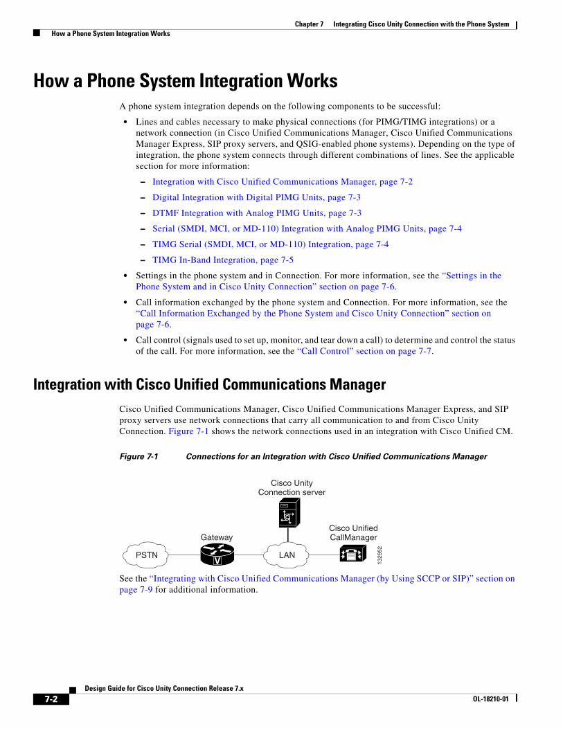
Chapter 7 Integrating Cisco Unity Connection with the Phone System How a Phone System Integration Works
How a Phone System Integration WorksA phone system integration depends on the following components to be successful:
• Lines and cables necessary to make physical connections (for PIMG/TIMG integrations) or a network connection (in Cisco Unified Communications Manager, Cisco Unified Communications Manager Express, SIP proxy servers, and QSIG-enabled phone systems). Depending on the type of integration, the phone system connects through different combinations of lines. See the applicable section for more information:
– Integration with Cisco Unified Communications Manager, page 7-2
– Digital Integration with Digital PIMG Units, page 7-3
– DTMF Integration with Analog PIMG Units, page 7-3
– Serial (SMDI, MCI, or MD-110) Integration with Analog PIMG Units, page 7-4
– TIMG Serial (SMDI, MCI, or MD-110) Integration, page 7-4
– TIMG In-Band Integration, page 7-5
• Settings in the phone system and in Connection. For more information, see the “Settings in the Phone System and in Cisco Unity Connection” section on page 7-6.
• Call information exchanged by the phone system and Connection. For more information, see the “Call Information Exchanged by the Phone System and Cisco Unity Connection” section on page 7-6.
• Call control (signals used to set up, monitor, and tear down a call) to determine and control the status of the call. For more information, see the “Call Control” section on page 7-7.
Integration with Cisco Unified Communications ManagerCisco Unified Communications Manager, Cisco Unified Communications Manager Express, and SIP proxy servers use network connections that carry all communication to and from Cisco Unity Connection. Figure 7-1 shows the network connections used in an integration with Cisco Unified CM.
Figure 7-1 Connections for an Integration with Cisco Unified Communications Manager
See the “Integrating with Cisco Unified Communications Manager (by Using SCCP or SIP)” section on page 7-9 for additional information.
Gateway
V
Cisco UnifiedCallManager
LANPSTN
1329
52
C
Cisco UnityConnection server
7-2Design Guide for Cisco Unity Connection Release 7.x
OL-18210-01

Chapter 7 Integrating Cisco Unity Connection with the Phone System How a Phone System Integration Works
Digital Integration with Digital PIMG UnitsThe phone system sends call information, MWI requests, and voice connections through the digital lines, which connect the phone system to the PIMG units (media gateways). The PIMG units communicate with the Cisco Unity Connection server through the LAN or WAN by using Session Initiation Protocol (SIP). Figure 7-2 shows the connections used in a digital integration by using digital PIMG units.
Figure 7-2 Connections for a Digital Integration by Using Digital PIMG Units
DTMF Integration with Analog PIMG UnitsThe phone system sends call information, MWI requests, and voice connections through the analog lines, which connect the phone system to the PIMG units (media gateways). The PIMG units communicate with the Cisco Unity Connection server through the LAN or WAN by using Session Initiation Protocol (SIP). Figure 7-3 shows the connections for a DTMF integration by using analog PIMG units.
Figure 7-3 Connections for a DTMF Integration by Using Analog PIMG Units
Digital linesNetwork connections
Phone system
1329
53
LAN/WANPIMG unit
AdditionalPIMG unitsas needed
PIMG unit
C
Cisco UnityConnection server
Analog linesNetwork connections
Phone system
1439
84
LAN/WANPIMG unit
AdditionalPIMG unitsas needed
PIMG unit
C
Cisco UnityConnection server
7-3Design Guide for Cisco Unity Connection Release 7.x
OL-18210-01

Chapter 7 Integrating Cisco Unity Connection with the Phone System How a Phone System Integration Works
Serial (SMDI, MCI, or MD-110) Integration with Analog PIMG UnitsThe phone system sends call information and MWI requests through the data link, which is an RS-232 serial cable that connects the phone system and the master PIMG unit (media gateways). Voice connections are sent through the analog lines between the phone system and the PIMG units. The PIMG units communicate with the Cisco Unity Connection server through the LAN or WAN by using Session Initialization Protocol (SIP). Figure 7-4 shows the connections for a serial integration by using analog PIMG units.
Figure 7-4 Connections for a Serial (SMDI, MCI, or MD-110) Integration by Using Analog PIMG
Units
Note When you use multiple PIMG units, one PIMG unit must be designated the master PIMG unit, which is connected to the serial cable from the phone system. It is not possible to “daisy chain” the serial ports on the PIMG units. You can add a secondary master PIMG unit to an integration. For details, see the “Appendix: Adding a Secondary Master PIMG Unit” appendix of the PIMG Integration Guide for Cisco Unity Connection Release 7.x.
TIMG Serial (SMDI, MCI, or MD-110) IntegrationThe TIMG integration uses one or more TIMG units between circuit-switched phone systems and IP networks. On the circuit-switched phone system side, there is a T1-CAS interface. On the IP side, there is a SIP interface, which is how Cisco Unity Connection communicates with the TIMG units. To Connection, the integration is essentially a SIP integration. Connection communicates with the TIMG units over the IP network by using SIP and RTP protocols. The TIMG units communicate with the circuit-switched phone system over the phone network by using serial protocols (SMDI, MCI, or MD-110).
The phone system sends call information and MWI requests through the data link, which is an RS-232 serial cable that connects the phone system and the master TIMG unit. Voice connections are sent through the T1 digital lines between the phone system and the TIMG units. The TIMG units
Analog linesRS-232 serial cableNetwork connections 15
3568
LAN/WANMaster PIMG unit
(SMDI data and calls)
Additionalslave PIMG units
as needed
Slave PIMG unit(calls only)
C
Cisco UnityConnection server
Phonesystem
7-4Design Guide for Cisco Unity Connection Release 7.x
OL-18210-01

Chapter 7 Integrating Cisco Unity Connection with the Phone System How a Phone System Integration Works
communicate with the Cisco Unity Connection server through the LAN or WAN by using Session Initialization Protocol (SIP). Figure 7-5 shows the connections for a serial integration by using TIMG units.
Figure 7-5 Connections for a Serial Integration by Using TIMG Units
TIMG In-Band IntegrationThe phone system sends call information, MWI requests, and voice connections through the T1 digital lines, which connect the phone system and the TIMG units. The TIMG units communicate with the Cisco Unity Connection server through the LAN or WAN by using Session Initialization Protocol (SIP). Figure 7-6 shows the required connections for an in-band integration by using TIMG units.
Figure 7-6 Connections for an In-Band Integration by Using TIMG Units
T1 digital lines (one or more)RS-232 serial cableNetwork connections 19
0677
LAN/WANMaster TIMG unit
(SMDI data and calls)
Additionalslave TIMG units
as needed
Slave TIMG unit(calls only)
C
Cisco UnityConnection server
Phonesystem
2503
81
LAN/WAN C
Cisco UnityConnection server
Phonesystem
T1 digital lines (one or more)Network connections
TIMG unit
TIMG unit
AdditionalTIMG unitsas needed
7-5Design Guide for Cisco Unity Connection Release 7.x
OL-18210-01

Chapter 7 Integrating Cisco Unity Connection with the Phone System How a Phone System Integration Works
Settings in the Phone System and in Cisco Unity ConnectionFor an integration to be successful, Cisco Unity Connection and the phone system must know the connections to use (for example, IP addresses and channels) and the expected method of communication (for example, IP packets, serial packets, and DTMF tones). Certain integrations require specific codes or extensions for turning MWIs on and off.
There are required settings for Connection, and programming for the phone system, that must be made in order to enable the integration. For information on these settings, see the applicable Cisco Unity Connection integration guide at http://www.cisco.com/en/US/products/ps6509/products_installation_and_configuration_guides_list.html.
Call Information Exchanged by the Phone System and Cisco Unity ConnectionThe phone system and Cisco Unity Connection exchange call information to manage calls and to make the integration features possible. With each call, the following call information is typically passed between the phone system and Connection:
• The extension of the called party.
• The extension of the calling party (for internal calls) or the phone number of the calling party (if it is an external call and the phone system supports caller ID).
• The reason for the forward (the extension is busy, does not answer, or is set to forward all calls). There is also a reason code for Direct Calls.
Cisco Unified Communications Manager SCCP and SIP trunk integrations can also provide the following call information:
• Called number
• First redirecting number
• Last redirecting number
Note Connection can use either the first redirecting number or last redirecting number, depending on the setting of the Use Last (Rather than First) Redirecting Number for Routing Incoming Call check box on the System Settings > Advanced > Conversations page in Cisco Unity Connection Administration.
If the phone system sends the necessary information and if Connection is configured correctly, an integration can provide the following integration functionality:
• Call forward to personal greeting
• Call forward to busy greeting
• Caller ID
• Easy message access (a user can retrieve messages without entering an ID because Connection identifies the user based on the extension from which the call originated; a password may be required)
• Identified user messaging (Connection identifies the user who leaves a message during a forwarded internal call, based on the extension from which the call originated)
• Message waiting indication (MWI)
7-6Design Guide for Cisco Unity Connection Release 7.x
OL-18210-01

Chapter 7 Integrating Cisco Unity Connection with the Phone System How a Phone System Integration Works
Call ControlThe phone system uses a set of signals to set up, monitor, and release connections for a call. Cisco Unity Connection monitors call control signals to determine the state of the call, and uses these signals to respond appropriately to phone system actions and to communicate with the phone system. For example, a caller who is recording a message might hang up, so Connection detects that the call has ended and stops recording.
Depending on the phone system, the following types of call control signals are used:
Sample Path for a Call from the Phone System to a UserThe following steps give an overview of a sample path that an external call can take when traveling from the phone system to a user.
1. For Cisco Unified Communications Manager, when an external call arrives, the gateway sends the call over the LAN or WAN to Cisco Unified CM. Cisco Unified CM routes the call to the Cisco Unity Connection voice mail pilot number.
For circuit-switched phone systems, when an external call arrives via the PSTN, TI/PRI, DID or LS/GS analog trunks, the phone system routes the call to the Cisco Unity Connection voice mail pilot number.
2. The phone system routes the call to an available Cisco Unity Connection voice messaging port.
3. Connection answers the call and plays the opening greeting.
4. During the opening greeting, the caller enters an extension. For example, the caller enters 1234 to reach a person at that extension.
5. Connection notifies the phone system that there is a call for extension 1234.
6. Depending on whether Connection is set up to perform a release transfer or a supervised transfer, the following occurs:
Cisco Unified Communications Manager For Skinny Call Control Protocol (SCCP) integrations, Cisco Unified Communications Manager generates SCCP messages, which are translated by Cisco Unity Connection.
For SIP trunk integrations, Cisco Unified CM sends SIP messages, and Connection sends SIP responses when a call is set up or terminated.
Circuit-switched phone system through PIMG/TIMG units
The phone system sends messages to the PIMG or TIMG units (media gateways), which send the applicable SIP messages to Connection. Connection sends SIP responses when a call is set up or terminated, and the PIMG or TIMG units communicate with the phone system.
Release transfer (blind transfer)
Connection passes the call to the phone system, and the phone system sends the call to extension 1234 without waiting to determine whether the line is available. Then the phone system and Connection drop out of the loop. In this configuration, if the customer wants Connection to take a message when a line is busy or unanswered, each phone must be configured to forward calls to Connection when the line is busy or unanswered.
7-7Design Guide for Cisco Unity Connection Release 7.x
OL-18210-01

Chapter 7 Integrating Cisco Unity Connection with the Phone System General Integration Issues
General Integration IssuesFor a detailed list of the requirements for a specific integration, see the applicable Cisco Unity Connection integration guide at http://www.cisco.com/en/US/products/ps6509/products_installation_and_configuration_guides_list.html.
If Cisco Unity Connection is configured for a Connection cluster, see the “Balancing the Load of Calls That the Cisco Unity Connection Servers Handle” section on page 8-4 and the “Configuration for Dial-out Voice Messaging Ports” section on page 8-5.
In addition, consider the following list of integration issues:
• Phone systems integrate with Connection only through a network connection.
• The license file for Connection may enable more voice messaging ports than the customer needs. Install only the number of ports that are needed, so that system resources are not allocated to unused ports, and do not exceed the port limitations set for the platform. For more information, see the Cisco Unity Connection Supported Platform List at http://www.cisco.com/en/US/products/ps6509/products_data_sheets_list.html. For additional information about configuring voice messaging ports, see the “Planning How the Voice Messaging Ports Will Be Used in Cisco Unity Connection” section in the applicable Cisco Unity Connection integration guide at http://www.cisco.com/en/US/products/ps6509/products_installation_and_configuration_guides_list.html.
Deploying Phones Across the WANSome deployment models, such as centralized messaging with distributed call processing, require placement of phones across the WAN from the Cisco Unity Connection server. When deploying phones across the WAN from the Connection server, see the “Cisco Voice Messaging” chapter of the Cisco Unified Communications SRND Based on Cisco Unified Communications Manager 7.x at http://www.cisco.com/en/US/docs/voice_ip_comm/cucm/srnd/7x/vmessage.html for guidance on capacity planning and call admission control (CAC) for these phones. When integrating Cisco Unity Connection with a circuit-switched phone system (TDM PBX), see the PIMG Integration Guide or the TIMG Integration Guide at http://www.cisco.com/en/US/products/ps6509/products_installation_and_configuration_guides_list.html for capacity planning for the PIMG/TIMG units deployed at these remote/branch sites to support phones at these sites.
Supervised transfer
While Connection holds the call, the phone system attempts to establish a connection with extension 1234.
If the line is available, the phone system connects the call from Connection to extension 1234. The phone system and Connection drop out of the loop, and the call is connected directly from the original caller to extension 1234.
If the line is busy or unanswered, the phone system gives that information to Connection, and Connection performs the operation the user has specified. For example, Connection takes a message.
7-8Design Guide for Cisco Unity Connection Release 7.x
OL-18210-01

Chapter 7 Integrating Cisco Unity Connection with the Phone System Integrating with Cisco Unified Communications Manager (by Using SCCP or SIP)
Integrating with Cisco Unified Communications Manager (by Using SCCP or SIP)
Revised May 2009Cisco Unity Connection supports Cisco Unified Communications Manager integrations through both SCCP and SIP interfaces. Table 7-1 shows the major differences in these integration methods.
For information on the compatibility of Connection and Cisco Unified CM versions, see the following documents:
• SCCP Compatibility Matrix: Cisco Unity Connection, Cisco Unified Communications Manager, and Cisco Unified Communications Manager Express at http://www.cisco.com/en/US/docs/voice_ip_comm/connection/compatibility/matrix/cucsccpmtx.html.
• SIP Trunk Compatibility Matrix: Cisco Unity Connection, Cisco Unified Communications Manager, and Cisco Unified Communications Manager Express at http://www.cisco.com/en/US/docs/voice_ip_comm/connection/compatibility/matrix/cucsiptrunkmtx.html.
For information on how to integrate Connection with Cisco Unified CM, see the applicable Cisco Unity Connection integration guide at http://www.cisco.com/en/US/products/ps6509/products_installation_and_configuration_guides_list.html.
For more information on using the SIP protocol to integrate Connection with Cisco Unified CM, see the “Integrating by Using SIP” section on page 7-20.
For information on the voice messaging solutions available for Cisco Unified CM, see the “Cisco Voice Messaging” chapter of the Cisco Unified Communications SRND Based on Cisco Unified Communications Manager 7.x at http://www.cisco.com/en/US/docs/voice_ip_comm/cucm/srnd/7x/vmessage.html.
Table 7-1 Differences Between SCCP and SIP Integration Methods (Integration with Cisco Unified Communications
Manager)
Feature SCCP SIP
Communication method SCCP Protocol SIP trunk
Cisco Unity Connection cluster (active/active high availability)
Supported Supported
Use of SCCP and SIP phones Supported Supported
Support for Cisco Unified CM versions Versions 4.1(x) and later Versions 5.x and later
Cisco Unified CM authentication and encryption Supported Supported (Cisco Unity Connection Release 7.x and later only)
First/last redirecting number Supported Supported
QOS Supported Supported
7-9Design Guide for Cisco Unity Connection Release 7.x
OL-18210-01

Chapter 7 Integrating Cisco Unity Connection with the Phone System Integrating with Cisco Unified Communications Manager (by Using SCCP or SIP)
Cisco Unified Communications Manager Authentication and Encryption for Cisco Unity Connection Voice Messaging Ports
A potential point of vulnerability for a Cisco Unity Connection system is the connection between Connection and Cisco Unified Communications Manager. Possible threats include:
• Man-in-the-middle attacks, in which an attacker intercepts and changes the data flowing between Cisco Unified CM and Connection voice messaging ports.
• Network traffic sniffing, in which an attacker captures phone conversations and signaling information that flow between Cisco Unified CM, the Connection voice messaging ports, and IP phones that are managed by Cisco Unified CM.
• Changing the call signaling between the Connection voice messaging ports and Cisco Unified CM.
• Changing the media stream between Connection voice messaging ports and endpoints, for example, phones or gateways.
• Identity theft of the Connection voice messaging port, in which a non-Connection device presents itself to Cisco Unified CM as a Connection voice messaging port.
• Identity theft of the Cisco Unified CM server, in which a non-Cisco Unified CM server presents itself to Connection voice messaging ports as a Cisco Unified CM server.
See the following sections for additional details:
• Cisco Unified Communications Manager Security Features, page 7-10
• When Data Is Encrypted, page 7-13
• Cisco Unified Communications Manager Cluster Security Mode Settings in Cisco Unity Connection, page 7-13
• Disabling and Reenabling Security, page 7-14
• Multiple Clusters Can Have Different Security Mode Settings, page 7-14
• Settings for Individual Voice Messaging Ports, page 7-14
• Packetization, page 7-15
Cisco Unified Communications Manager Security Features
Cisco Unified Communications Manager Release 4.1(3) or later for SCCP integrations or Cisco Unified Communications Manager Release 7.x or later for SIP trunk integrations can secure the connection with Cisco Unity Connection against security threats. The Cisco Unified CM security features that Connection can take advantage of are described in Table 7-2.
7-10Design Guide for Cisco Unity Connection Release 7.x
OL-18210-01

Chapter 7 Integrating Cisco Unity Connection with the Phone System Integrating with Cisco Unified Communications Manager (by Using SCCP or SIP)
Table 7-2 Cisco Unified Communications Manager Security Features That Are Used by Cisco Unity Connection
Security Feature Description
Signaling authentication Uses the Transport Layer Security (TLS) protocol to validate that no tampering has occurred to signaling packets during transmission. Signaling authentication relies on the creation of the Cisco Certificate Trust List (CTL) file.
This feature protects against:
• Man-in-the-middle attacks that modify the information flow between Cisco Unified CM and the Connection voice messaging ports.
• Modification of the call signaling.
• Identity theft of the Connection voice messaging port.
• Identity theft of the Cisco Unified CM server.
Device authentication Validates the identity of the device. This process occurs between Cisco Unified CM and the Connection voice messaging ports when each device accepts the certificate of the other device. When the certificates are accepted, a secure connection between the devices is established. Device authentication relies on the creation of the Cisco Certificate Trust List (CTL) file.
This feature protects against:
• Man-in-the-middle attacks that modify the information flow between Cisco Unified CM and the Connection voice messaging ports.
• Modification of the media stream.
• Identity theft of the Connection voice messaging port.
• Identity theft of the Cisco Unified CM server.
Signaling encryption Uses cryptographic methods to protect (through encryption) the confidentiality of all SCCP and SIP signaling messages that are sent between the Connection voice messaging ports and Cisco Unified CM. Signaling encryption ensures that the information that pertains to the parties, DTMF digits that are entered by the parties, call status, media encryption keys, and so on are protected against unintended or unauthorized access.
This feature protects against:
• Man-in-the-middle attacks that observe the information flow between Cisco Unified CM and the Connection voice messaging ports.
• Network traffic sniffing that observes the signaling information flow between Cisco Unified CM and the Connection voice messaging ports.
7-11Design Guide for Cisco Unity Connection Release 7.x
OL-18210-01

Chapter 7 Integrating Cisco Unity Connection with the Phone System Integrating with Cisco Unified Communications Manager (by Using SCCP or SIP)
Note that Cisco Unified CM authentication and encryption protects only calls to Connection. Messages that are recorded on Connection are not protected by Cisco Unified CM authentication and encryption but can be protected by the Connection secure messaging feature.
For more information on secure messaging, see the “Securing User Messages: Controlling Access and Distribution” chapter of the System Administration Guide for Cisco Unity Connection Release 7.x.
The security features (authentication and encryption) between Connection and Cisco Unified CM require the following for SCCP integrations:
• A Cisco Unified CM CTL file that lists all Cisco Unified CM servers that are entered in Cisco Unity Connection Administration for secure clusters.
• A Connection server root certificate for each Connection server that uses authentication and/or encryption. A root certificate is valid for 20 years from the time it was created.
• Connection voice messaging port or port group device certificates that are rooted in the Connection server root certificate, and voice messaging ports or port groups that are present when registering with the Cisco Unified CM server.
The process of authentication and encryption of Connection voice messaging SCCP ports occurs as follows:
1. Each Connection voice messaging port connects to the TFTP server, via TFTP port 69, downloads the CTL file, and extracts the certificates for all Cisco Unified CM servers.
2. Each Connection voice messaging port establishes a network connection to the Cisco Unified CM TLS port. By default, the TLS port is 2443, though the port number is configurable.
3. Each Connection voice messaging port establishes a TLS connection to the Cisco Unified CM server, at which time the device certificate is verified and the voice messaging port is authenticated.
4. Each Connection voice messaging port registers with the Cisco Unified CM server, specifying whether the voice messaging port will also use media encryption.
Media encryption Uses Secure Real Time Protocol (SRTP) as defined in IETF RFC 3711 to ensure that only the intended recipient can interpret the media streams between the Connection voice messaging ports and endpoints (for example, phones or gateways). Only audio streams are encrypted. Media encryption creates a media master key pair for the devices, delivers the keys to Connection and the endpoint, and secures the delivery of the keys while the keys are in transport. Connection and the endpoint use the keys to encrypt and decrypt the media stream.
This feature protects against:
• Man-in-the-middle attacks that listen to the media stream between Cisco Unified CM and the Connection voice messaging ports.
• Network traffic sniffing that eavesdrops on phone conversations that flow between Cisco Unified CM, the Connection voice messaging ports, and IP phones that are managed by Cisco Unified CM.
Authentication and signaling encryption are required for media encryption; that is, if the devices do not support authentication and signaling encryption, media encryption cannot occur.
Table 7-2 Cisco Unified Communications Manager Security Features That Are Used by Cisco Unity Connection
Security Feature Description
7-12Design Guide for Cisco Unity Connection Release 7.x
OL-18210-01

Chapter 7 Integrating Cisco Unity Connection with the Phone System Integrating with Cisco Unified Communications Manager (by Using SCCP or SIP)
The process of authentication and encryption of Connection voice messaging SIP port groups occurs as follows:
1. Each Connection voice messaging port group connects to the TFTP server, via TFTP port 69, downloads the CTL file, and extracts the certificates for all Cisco Unified CM servers.
2. Each Connection voice messaging port group establishes a network connection to the Cisco Unified CM TLS port. By default, the TLS port is 2443, though the port number is configurable.
3. Each Connection voice messaging port group establishes a TLS connection to the Cisco Unified CM server, at which time the device certificate is verified and the voice messaging port group is authenticated.
4. Each Connection voice messaging port group registers with the Cisco Unified CM server, specifying whether the voice messaging port group will also use media encryption.
When Data Is Encrypted
When a call is made between Cisco Unity Connection and Cisco Unified CM, the call-signaling messages and the media stream are handled in the following manner:
• If both endpoints are set for encrypted mode, the call-signaling messages and the media stream are encrypted.
• If one endpoint is set for authenticated mode and the other endpoint is set for encrypted mode, the call-signaling messages are authenticated. But neither the call-signaling messages nor the media stream are encrypted.
• If one endpoint is set for non-secure mode and the other endpoint is set for encrypted mode, neither the call-signaling messages nor the media stream are encrypted.
Cisco Unified Communications Manager Cluster Security Mode Settings in Cisco Unity Connection
The Security Mode settings in Cisco Unity Connection Administration determine how the ports handle call-signaling messages and whether encryption of the media stream is possible. Table 7-3 describes the effect of the Security Mode settings on the Telephony Integrations > Port > Port Basics page for each port in an SCCP integration.
Table 7-3 Security Mode Settings for Voice Messaging Ports in an SCCP Integration
Setting Effect
Non-secure The integrity and privacy of call-signaling messages will not be ensured because call-signaling messages are sent as clear (unencrypted) text and are connected to Cisco Unified CM through a non-authenticated port rather than an authenticated TLS port.
In addition, the media stream cannot be encrypted.
Authenticated The integrity of call-signaling messages is ensured because they are connected to Cisco Unified CM through an authenticated TLS port. However, the privacy of call-signaling messages is not ensured because they are sent as clear (unencrypted) text.
In addition, the media stream is not encrypted.
7-13Design Guide for Cisco Unity Connection Release 7.x
OL-18210-01

Chapter 7 Integrating Cisco Unity Connection with the Phone System Integrating with Cisco Unified Communications Manager (by Using SCCP or SIP)
Disabling and Reenabling Security
The authentication and encryption features between Cisco Unity Connection and Cisco Unified CM can be enabled and disabled by changing the Security Mode for all Cisco Unified CM clusters to Non-Secure, and by changing the applicable settings in the Cisco Unified Communications Manager Administration.
Authentication and encryption can be reenabled by changing the Security Mode to Authenticated or Encrypted.
Note After disabling or re-enabling authentication and encryption, it is not necessary to export the Connection server root certificate and copy it to all Cisco Unified CM servers.
Multiple Clusters Can Have Different Security Mode Settings
When Cisco Unity Connection has multiple Cisco Unified CM phone system integrations, each Cisco Unified CM phone system integration can have different Security Mode settings. For example, one Cisco Unified CM phone system integration can be set to Encrypted, and a second Cisco Unified CM phone system integration can be set to Non-Secure.
Settings for Individual Voice Messaging Ports
For troubleshooting purposes, authentication and encryption for Cisco Unity Connection voice messaging ports can be individually enabled and disabled. At all other times, we recommend that the Security Mode setting for all individual voice messaging ports in a Cisco Unified CM port group be the same.
Encrypted The integrity and privacy of call-signaling messages is ensured because they are connected to Cisco Unified CM through an authenticated TLS port, and the call-signaling messages are encrypted.
In addition, the media stream can be encrypted.
Caution Both endpoints must be registered in encrypted mode for the media stream to be encrypted. However, when one endpoint is set for non-secure or authenticated mode and the other endpoint is set for encrypted mode, the media stream is not encrypted. Also, if an intervening device (such as a transcoder or gateway) is not enabled for encryption, the media stream is not encrypted.
Table 7-3 Security Mode Settings for Voice Messaging Ports in an SCCP Integration (continued)
Setting Effect
7-14Design Guide for Cisco Unity Connection Release 7.x
OL-18210-01

Chapter 7 Integrating Cisco Unity Connection with the Phone System Integrating with Cisco Unified Communications Manager Express (by Using SCCP or SIP)
Packetization
The Real-Time Transport Protocol (RTP) is used to send and receive audio packets over the IP network. Each discrete packet has a fixed-size header, but the packets themselves can vary in size, depending on the size of the audio stream to be transported (which varies by codec) and the packetization setting. This variable size function helps utilize network bandwidth more efficiently. Reducing the number of packets that are created per call sends fewer total bytes over the network.
Packetization is set in the Cisco Unified CM Service Parameters, in the Preferred G711 Millisecond PacketSize and Preferred G729 Millisecond PacketSize parameters. Cisco Unity Connection supports any packet size up to 30ms for G.711 audio, and any packet size up to 60 ms for G.729a audio. The default setting is 20ms for both; there may be latency issues with lower settings.
DSCP is a priority setting on each packet. DSCP helps intermediary routers manage network congestion and lets them know which packets to prioritize ahead of others. Following Cisco AVVID standards, Connection marks the SCCP and SIP packets (call control) with a default DSCP value of 24 (the TOS octet is 0x60), and the RTP packets (audio traffic) with a default DSCP value of 46 (the TOS octet is 0xB8). Thus, the RTP audio packets can be assigned priority over other packets by using the router settings. Note that even though Cisco Unified CM allows you set different DSCP values, when integrated with Connection, the DSCP values set by Connection always take precedence. The marking of both SCCP and SIP packets is configurable in Connection on the System Settings > Advanced > Telephony Configuration page in Cisco Unity Connection Administration.
With each new audio stream (once per call), Cisco Unified CM tells Connection which packet size to use, and Connection sets the DSCP priority for the stream. The entire stream (call) stays at the specified packet size and priority. For example, an audio stream could be broken up into packets of 30ms each. A 30ms G.729a audio stream would be 30 bytes plus the header per packet, and a 30ms G.711 stream would be 240 bytes plus the header per packet. For information on setting Cisco Unified CM Service Parameters, see the Cisco Unified CM documentation at http://www.cisco.com/en/US/products/sw/voicesw/ps556/tsd_products_support_series_home.html.
Note You can change the codecs that Connection advertises on the Telephony Integrations > Port Group > Edit Codec Advertising configuration page in Cisco Unity Connection Administration. For a discussion of supported advertised or “on the line” audio codecs and system-level recording audio codecs, see the “Audio Codecs” section on page 3-1.
Integrating with Cisco Unified Communications Manager Express (by Using SCCP or SIP)
Cisco Unity Connection supports Cisco Unified Communications Manager Express integrations through both SCCP and SIP interfaces. Figure 7-7 shows the connections.
7-15Design Guide for Cisco Unity Connection Release 7.x
OL-18210-01

Chapter 7 Integrating Cisco Unity Connection with the Phone System Integrating with Cisco Unified Communications Manager Express (by Using SCCP or SIP)
Figure 7-7 Cisco Unity Connection SCCP and SIP Connections to Cisco Unified Communications
Manager Express Over a LAN
See Table 7-4 for information on the differences in these integration methods.
For information on the compatibility of Connection and Cisco Unified Communications Manager Express versions, see the following:
• SCCP Compatibility Matrix: Cisco Unity Connection, Cisco Unified Communications Manager, and Cisco Unified Communications Manager Express at http://www.cisco.com/en/US/docs/voice_ip_comm/connection/compatibility/matrix/cucsccpmtx.html.
• SIP Trunk Compatibility Matrix: Cisco Unity Connection, Cisco Unified Communications Manager, and Cisco Unified Communications Manager Express at http://www.cisco.com/en/US/docs/voice_ip_comm/connection/compatibility/matrix/cucsiptrunkmtx.html.
For information on how to integrate Connection with Cisco Unified CM Express, see the applicable Cisco Unity Connection integration guide at http://www.cisco.com/en/US/products/ps6509/products_installation_and_configuration_guides_list.html.
For more information on using the SIP protocol to integrate Connection with Cisco Unified CM Express, see the “Integrating by Using SIP” section on page 7-20.
Cisco UnifiedCommunicationsManager Express
LANPSTN
1918
59
Cisco UnityConnection server
C
Table 7-4 Differences Between SCCP and SIP Integration Methods (Integration with Cisco
Unified Communications Manager Express)
Feature SCCP SIP
Communication method SCCP SIP trunk
Cisco Unity Connection cluster (active/active high availability)
Supported Supported
Use of SCCP and SIP phones Supported Some SCCP phones may require use of a media termination point (MTP)
Support for Cisco Unified CM Express versions
All versions Versions 3.4 and later
Cisco Unified CM Express authentication and encryption
Not supported Not supported
First/last redirecting number Supported Supported
QOS Supported Supported
7-16Design Guide for Cisco Unity Connection Release 7.x
OL-18210-01

Chapter 7 Integrating Cisco Unity Connection with the Phone System Integrating with Cisco Unified Communications Manager Express (by Using SCCP or SIP)
Multiple Cisco Unified Communications Manager Express Version SupportA single Cisco Unity Connection server can support multiple versions of Cisco Unified CM Express. The version of Connection being used must support all versions of Cisco Unified CM Express. See the following documents:
• SCCP Compatibility Matrix: Cisco Unity Connection, Cisco Unified Communications Manager, and Cisco Unified Communications Manager Express at http://www.cisco.com/en/US/docs/voice_ip_comm/connection/compatibility/matrix/cucsccpmtx.html.
• SIP Trunk Compatibility Matrix: Cisco Unity Connection, Cisco Unified Communications Manager, and Cisco Unified Communications Manager Express at http://www.cisco.com/en/US/docs/voice_ip_comm/connection/compatibility/matrix/cucsiptrunkmtx.html.
Multiple Cisco Unified Communications Manager Express Routers Integrating with a Single Cisco Unity Connection Server
A single, centralized Cisco Unity Connection server can be used by multiple Cisco Unified CM Express routers. This configuration requires that one Cisco Unified CM Express router be on the same LAN as the Connection server, and that this Cisco Unified CM Express router register all Connection voice messaging ports. This Cisco Unified CM Express router (the SIP MWI server) is a proxy server that relays SIP MWI messages between the Connection server and all other Cisco Unified CM Express routers (the SIP MWI clients). Note that Connection voice messaging ports register only with the SIP MWI server (the Cisco Unified CM Express router that is on the same LAN as the Connection server), not with the SIP MWI clients. See Figure 7-8.
Figure 7-8 Connections between Multiple Cisco Unified CM Express Routers and a Single
Cisco Unity Connection Server
For information on configuring Connection to support multiple Cisco Unified CM Express routers, see the applicable Cisco Unity Connection integration guide at http://www.cisco.com/en/US/products/ps6509/products_installation_and_configuration_guides_list.html.
Cisco UnifiedCommunicationsManager Express
LANPSTN
1918
60
Cisco UnifiedCommunicationsManager Express
SIP MWI server SIP MWI client
Cisco UnityConnection server
C
7-17Design Guide for Cisco Unity Connection Release 7.x
OL-18210-01

Chapter 7 Integrating Cisco Unity Connection with the Phone System Integrating Cisco Unity Connection with Multiple Versions of Cisco Unified Communications Manager and Cisco
Integrating Cisco Unity Connection with Multiple Versions of Cisco Unified Communications Manager and Cisco Unified Communications Manager Express
A single Cisco Unity Connection server can support multiple versions of Cisco Unified Communications Manager and Cisco Unified Communications Manager Express. The Connection version must support all versions of Cisco Unified CM and/or Cisco Unified CM Express. See the following documents:
• SCCP Compatibility Matrix: Cisco Unity Connection, Cisco Unified Communications Manager, and Cisco Unified Communications Manager Express at http://www.cisco.com/en/US/docs/voice_ip_comm/connection/compatibility/matrix/cucsccpmtx.html.
• SIP Trunk Compatibility Matrix: Cisco Unity Connection, Cisco Unified Communications Manager, and Cisco Unified Communications Manager Express at http://www.cisco.com/en/US/docs/voice_ip_comm/connection/compatibility/matrix/cucsiptrunkmtx.html.
Integrating Cisco Unity Connection with Cisco Unified Survivable Remote Site Telephony (Cisco Unified SRST)
Cisco Unified Survivable Remote Site Telephony (SRST) can send and receive voice messages from Cisco Unity Connection during Cisco Unified CM fallback. When the WAN is down and Connection has Basic Rate Interface (BRI) or Primary Rate Interface (PRI) access to the Cisco Unified SRST system, Connection uses ISDN signaling (see Figure 7-9).
Figure 7-9 Cisco Unified Communications Manager Fallback with BRI or PRI
When the WAN is down and Connection has foreign exchange office (FXO) or foreign exchange station (FXS) access to a public switched telephone network (PSTN), Connection uses in-band dual tone multifrequency (DTMF) signaling (see Figure 7-10).
IP
IP
IP
88
98
1
Cisco CallManager
Voice-Mail Server
CM Gateway
BRI/PRI
SRST Gateway
WAN
WAN FailureWAN FailureWAN Failure
7-18Design Guide for Cisco Unity Connection Release 7.x
OL-18210-01

Chapter 7 Integrating Cisco Unity Connection with the Phone System Integrating Cisco Unity Connection with Cisco Unified Survivable Remote Site Telephony (Cisco Unified SRST)
Figure 7-10 Cisco Unified Communications Manager Fallback with PSTN
In both configurations, phone message buttons remain active and calls to busy or unanswered numbers are forwarded to Connection. The installer must configure access from the dial peers to the voice-mail system, and establish routing to Connection for busy and unanswered calls and for the message button.
If Connection is accessed over FXO or FXS, you must configure instructions (DTMF patterns) for Connection so it can access the correct voice-mail system mailbox.
When using Cisco Unified SRST with Connection, the integration has the following limitations during a WAN outage:
• Call forward to busy greeting—When the Cisco Unified SRST router uses FXO/FXS connections to the PSTN and a call is forwarded from a branch office to Connection, the busy greeting cannot play.
• Call forward to internal greeting—When the Cisco Unified SRST router uses FXO/FXS connections to the PSTN and a call is forwarded from a branch office to Connection, the internal greeting cannot play. Because the PSTN provides the calling number of the FXO line, the caller is not identified as a user.
• Call transfers—Because an access code is needed to reach the PSTN, call transfers from Connection to a branch office will fail.
• Identified user messaging—When the Cisco Unified SRST router uses FXO/FXS connections to the PSTN and a user at a branch office leaves a message or forwards a call, the user is not identified. The caller appears as an unidentified caller.
• Message waiting indication—MWIs are not updated on branch office phones, so MWIs will not correctly reflect when new messages arrive or when all messages have been listened to. We recommend resynchronizing MWIs after the WAN link is reestablished.
• Message notification—Because an access code is needed to reach the PSTN, message notifications from Connection to a branch office will fail.
• Routing rules—When the Cisco Unified SRST router uses FXO/FXS connections to the PSTN and a call arrives from a branch office to Connection (either a direct or forwarded call), routing rules will fail.
When the Cisco Unified SRST router uses PRI or BRI connections, the caller ID for calls from a branch office to Connection may be the full number (exchange plus extension) provided by the PSTN and therefore may not match the extension of the Connection user. In this case, you can let Connection recognize the caller ID by using alternate extensions.
IP
IP
IP
8898
0
Cisco CallManager
Voice-mail server
Cisco CallManager gateway
FXS
PSTN
FXO
WAN
WAN failure
7-19Design Guide for Cisco Unity Connection Release 7.x
OL-18210-01

Chapter 7 Integrating Cisco Unity Connection with the Phone System Integrating by Using SIP
When using Cisco Unified SRST, Redirected Dialed Number Information Service (RDNIS) must be supported.
For information on setting up Cisco Unified SRST routers, see the “Integrating Voice Mail with Cisco Unified SRST” chapter of the Cisco Unified SRST System Administrator Guide at http://www.cisco.com/en/US/products/sw/voicesw/ps2169/products_installation_and_configuration_guides_list.html.
Impact of Non-Delivery of RDNIS on Voice Mail Calls Routed by Using AARRDNIS must be supported when using Automated Alternate Routing (AAR).
AAR can route calls over the PSTN when the WAN is oversubscribed. However, when calls are rerouted over the PSTN, RDNIS can be affected. Incorrect RDNIS information can affect voice mail calls that are rerouted over the PSTN by AAR when Cisco Unity Connection is remote from its messaging clients. If the RDNIS information is not correct, the caller does not reach the mailbox of the dialed user but instead hears the automated attendant prompt, and might be asked to reenter the extension number of the party the caller wants to reach. This behavior is primarily an issue when the phone carrier is unable to ensure RDNIS across the network. There are numerous reasons why the carrier might not be able to ensure that RDNIS is properly sent. Check with your carrier to determine whether it provides guaranteed RDNIS delivery end-to-end for your circuits. The alternative to using AAR for oversubscribed WANs is simply to let callers hear reorder tone in an oversubscribed condition.
Integrating Cisco Unity Connection with Cisco Unified Communications Manager Express in SRST Mode
Cisco Unity Connection supports a topology with centralized call processing and distributed messaging, in which your Connection server is located at a remote site or branch office and registered with Cisco Unified CM at a central site.
When the WAN link fails, the phones fall back to the Cisco Unified CM Express-as-SRST device. Connection can also fall back to the Cisco Unified CM Express-as-SRST device, which lets users at the remote site access their voice messages and see message waiting indicators (MWIs) during a WAN outage. Note that MWIs must be resynchronized from the Connection server whenever a failover happens from Cisco Unified CM to Cisco Unified CM Express-as-SRST or vice versa.
For information on setting up this configuration, see the Integrating Cisco Unity Connection with Cisco Unified CME-as-SRST configuration guide at http://www.cisco.com/en/US/products/sw/voicesw/ps4625/products_installation_and_configuration_guides_list.html.
Integrating by Using SIPSIP (Session Initiation Protocol) is the Internet Engineering Task Force standard for multimedia calls over IP. SIP is a peer-to-peer, ASCII-based protocol that uses requests and responses to establish, maintain, and terminate calls (or sessions) between two or more end points. See Table 7-5.
7-20Design Guide for Cisco Unity Connection Release 7.x
OL-18210-01

Chapter 7 Integrating Cisco Unity Connection with the Phone System Integrating by Using SIP
Cisco Unity Connection accepts calls from a proxy server. Connection relies on a proxy server or call agent to authenticate calls.
SIP uses a request/response method to establish communications between various components in the network and to ultimately establish a conference (call or session) between two or more endpoints. A single call may involve several clients and servers.
Users in a SIP network are identified by:
• A unique phone or extension number.
• A unique SIP address, which is similar to an email address and uses the format sip:<userID>@<domain>. The user ID can be either a user name or an E.164 address.
When a user initiates a call, a SIP request typically goes to a SIP server (either a proxy server or a redirect server). The request includes the caller address (From) and the address of the called party (To).
SIP messages are in text format using ISO 10646 in UTF-8 encoding (like HTML). In addition to the address information, a SIP message contains a start-line specifying the method and the protocol, a number of header fields specifying call properties and service information, and an optional message body which can contain a session description.
Supported SIP IntegrationsCisco Unity Connection supports the following SIP integrations:
• SIP trunks to supported versions of Cisco Unified Communications Manager and Cisco Unified Communications Manager Express. For a list of Cisco Unified CM and Cisco Unified CM Express versions supported as SIP trunks, see SIP Trunk Compatibility Matrix: Cisco Unity Connection,
Table 7-5 SIP Network Components
Component Description
SIP proxy server An intermediate device that receives SIP requests from a client and then forwards the requests on behalf of the client. Proxy servers receive SIP messages and forward them to the next SIP server in the network. Proxy servers can provide functions such as authentication, authorization, network access control, routing, reliable request retransmission, and security.
Redirect server Provides information to the client about the next hop or hops that a message should take. The client then contacts the next hop server or user-agent server directly.
Registrar server Processes requests from user agent clients for registration of their current location. Registrar servers are often installed on the redirect or proxy server.
Phones Acts as either a server or client. Softphones (PCs that have phone capabilities installed) and Cisco SIP IP phones can initiate SIP requests and respond to requests.
Gateways Provide call control. Gateways provide many services; the most common is a translation function between SIP call endpoints and other terminal types. This function includes translation between transmission formats and between communications procedures. In addition, the gateway translates between audio and video codecs, and performs call setup and clearing on both the LAN side and the switched-circuit network side.
7-21Design Guide for Cisco Unity Connection Release 7.x
OL-18210-01
Chapter 7 Integrating Cisco Unity Connection with the Phone System Integrating with Circuit-Switched Phone Systems by Using PIMG or TIMG Units
Cisco Unified Communications Manager, and Cisco Unified Communications Manager Express at http://www.cisco.com/en/US/docs/voice_ip_comm/connection/compatibility/matrix/cucsiptrunkmtx.html.
• Cisco SIP Proxy Server (CSPS).
• Cisco ISR voice gateways for integrating Connection to a QSIG-enabled phone system (see the “Integrating Cisco Unity Connection with a QSIG-Enabled Phone System by Using Cisco ISR Voice Gateways” section on page 7-27.
Third-party SIP trunks are currently not supported.
For more information on configuring SIP trunks between Connection and Cisco Unified CM or Cisco Unified CM Express, see the applicable SIP trunk integration guide at http://www.cisco.com/en/US/products/ps6509/products_installation_and_configuration_guides_list.html.
Integrating with Circuit-Switched Phone Systems by Using PIMG or TIMG Units
Cisco Unity Connection can integrate with circuit-switched phone systems by using the PIMG or TIMG units (media gateways) between circuit-switched phone systems and IP networks.
For a list of circuit-switched phone systems supported with Connection by using PIMG and TIMG integrations, see the applicable Cisco Unity Connection integration guide at http://www.cisco.com/en/US/products/ps6509/products_installation_and_configuration_guides_list.html.
Description of PIMG IntegrationsThe PIMG integration uses one or more PIMG units between the circuit-switched phone systems and IP network. On the circuit-switched phone system side, there are both digital (feature-set) and analog interfaces; the interface used depends on the phone system to which Cisco Unity Connection is connected. On the IP side, there is a SIP interface, which is how Connection communicates with the PIMG units. To Connection, the integration is essentially a SIP integration. Connection communicates with the PIMG units over the IP network by using SIP and RTP protocols. The PIMG units communicate with the circuit-switched phone system over the phone network using phone system-specific protocols (digital, analog, or serial).
For high-level descriptions of each PIMG integration type, and illustrations showing the network connections, see the “How a Phone System Integration Works” section on page 7-2.
Setup and ConfigurationFor PIMG/TIMG setup and configuration, the installer does the following steps as documented in the applicable integration guide:
1. Configure the phone system.
2. Configure the PIMG/TIMG units. PIMG/TIMG settings are somewhat phone system-specific, but less so than phone system configuration.
3. Configure Cisco Unity Connection for the integration.
7-22Design Guide for Cisco Unity Connection Release 7.x
OL-18210-01

Chapter 7 Integrating Cisco Unity Connection with the Phone System Integrating with Circuit-Switched Phone Systems by Using PIMG or TIMG Units
For information on configuring the phone system, PIMG/TIMG units, and Connection, see the applicable Cisco Unity Connection integration guide at http://www.cisco.com/en/US/products/ps6509/products_installation_and_configuration_guides_list.html.
Firmware UpdatesNote that when receiving shipment of PIMG or TIMG units, it may be necessary to update the firmware on the units. The PIMG/TIMG Administration interface provides a simple method to update the firmware files. Firmware updates are available at http://tools.cisco.com/support/downloads/go/Redirect.x?mdfid=278875240 (note that you must log on to www.cisco.com to access the URL). For details, see the applicable integration guide.
Serial IntegrationsCisco Unity Connection supports the following serial protocols:
• SMDI
• MCI
• MD-110
The serial port on PIMG/TIMG units was originally designed as a management port rather than as a standard RS-232 serial port. Consequently, a custom serial cable (which is available from Cisco) is necessary for the data link between the phone system and the master PIMG/TIMG unit.
Increasing Port CapacityPIMG units have eight ports. To increase system port capacity, multiple PIMG units can be stacked. For example, if 32 ports are needed, four PIMG units can be stacked.
TIMG units, which integrate with circuit-switched phone systems that support T1-CAS, have 24 T1 ports per span in a single rack-optimized unit. Single-span, dual-span, and quad-span TIMG units are available.
Cisco Unity Connection ClustersPIMG/TIMG integrations support Cisco Unity Connection clusters (active/active high availability). Configuration changes are required both for the PIMG/TIMG units and for the Connection servers, as described in the applicable Cisco Unity Connection integration guide at http://www.cisco.com/en/US/products/ps6509/products_installation_and_configuration_guides_list.html.
Multiple Integration Support/Branch Office ConsolidationPIMG/TIMG units can be separated by a WAN to support circuit-switched phone systems at remote branch office sites. For example, Cisco Unity Connection could be placed at a centralized headquarters and support circuit-switched phone systems both at the headquarters and at the branch office sites.
7-23Design Guide for Cisco Unity Connection Release 7.x
OL-18210-01

Chapter 7 Integrating Cisco Unity Connection with the Phone System Integrating with Multiple Phone Systems
As an example, assuming there are four phone systems from four different manufacturers (for example, Nortel, Avaya, NEC, and Siemens), four different phone system integrations could be created on the Connection server to support the four phone systems. A standalone Connection server supports up to 144 ports that will connect to the four phone systems. For example:
• At the Seattle site, 15 PIMG units can be stacked to support 120 ports.
• At the New York site, two PIMG units can be stacked to support 16 ports.
• At the Tokyo site, one PIMG unit can be used to support four ports.
• At the Dallas site, one PIMG unit can be used to support two ports.
Note that even though the PIMG units come with eight ports, fewer than eight ports can be used on each unit.
If PIMG units will be separated by a WAN to support remote phone systems, correct audio codec selection, bandwidth capacity planning, and QOS planning are required. Both the G.729a and G.711 audio codecs are supported by PIMG units and by Connection. Because PIMG units are Dialogic devices rather than Cisco devices, the use of location-based CAC is not applicable. The following network and bandwidth requirements are required when placing the PIMG across a WAN:
• For the G.729a audio codec, a minimum of 32.76 Kbps (assumes Ethernet, payload of 20 bytes, 5 percent overhead) guaranteed bandwidth for each voice messaging port.
• For the G.711 audio codec, a minimum of 91.56 Kbps (assumes Ethernet, payload of 160 bytes, 5 percent overhead) guaranteed bandwidth for each voice messaging port.
• No network devices that implement network address translation (NAT).
When PIMG units are separated by a WAN, prioritize your call control and media traffic through proper QOS traffic, marking for voice traffic originating on the PIMG units. Set the Call Control QOS Byte and RTP QOS Byte on PIMG units to the following values:
• In the Call Control QOS Byte field, enter 104.
• In the RTP QOS Byte field, enter 184.
Note that the Call Control QOS Byte and RTP QOS Byte fields on PIMG units define a decimal value that represents QOS bit flags. These values can be interpreted as either IPv4 TOS or Differentiated Services Codepoint (DSCP). For more details, see the Dialogic 1000 and 2000 Media Gateway Series User’s Guide, provided by Dialogic.
Integrating with Multiple Phone SystemsCisco Unity Connection supports as many phone systems as needed up to the maximum number of ports supported per Connection server or active/active server pair (a Connection cluster). See the Multiple Phone System Integration Guide for Cisco Unity Connection 7.x at http://www.cisco.com/en/US/docs/voice_ip_comm/connection/7x/integration/misc/guide/cuc7xintmultiple.html.
7-24Design Guide for Cisco Unity Connection Release 7.x
OL-18210-01

Chapter 7 Integrating Cisco Unity Connection with the Phone System Integrating with Multiple Phone Systems
Requirements for Integrations with Multiple Phone SystemsCisco Unity Connection has the following requirements for multiple phone system integrations:
• All phone system and Connection server requirements have been met. See the applicable Cisco Unity Connection integration guide at http://www.cisco.com/en/US/products/ps6509/products_installation_and_configuration_guides_list.html.
• There must be an adequate number of voice messaging ports on the Connection server to connect to the phone systems. This number of ports must not exceed the number of ports that are enabled by the Connection license files.
• Connection is installed on a separate server from Cisco Unified CM. Multiple integrations are not supported when Connection is installed as Cisco Unified Communications Manager Business Edition (CMBE)—on the same server with Cisco Unified CM.
Optional Integration FeaturesSee the following sections:
• Alternate Extensions, page 7-25
• Alternate MWIs, page 7-25
Alternate Extensions
In addition to the primary extension for each user, you can set up alternate extensions. Alternate extensions can be used for various reasons, such as handling multiple line appearances on user phones. Alternate extensions can also make calling Cisco Unity Connection from an alternate device—such as a mobile phone, a home phone, or a phone at another work site—more convenient.
When you specify the phone number for an alternative extension, Connection handles all calls from that number in the same way that it handles calls from a primary extension (assuming that ANI or caller ID is passed along to Connection from the phone system). This means that Connection associates the alternate phone number with the user account, and when a call comes from that number, Connection prompts the user to enter a password and log on.
Alternate MWIs
You can set up Cisco Unity Connection to activate alternate MWIs when you want a new message for a user to activate the MWIs at up to 10 extensions. For example, a message left at extension 1001 can activate the MWIs on extensions 1001 and 1002.
Connection uses MWIs to alert the user to new voice messages. MWIs are not used to indicate new email, fax, or return receipt messages.
Centralized Voice MessagingRevised July 9, 2009Cisco Unity Connection supports centralized voice messaging through the phone system, which supports various inter-phone system networking protocols including proprietary protocols such as Avaya DCS, Nortel MCDN, or Siemens CorNet, and standards-based protocols such as QSIG or DPNSS. Note that
7-25Design Guide for Cisco Unity Connection Release 7.x
OL-18210-01
Chapter 7 Integrating Cisco Unity Connection with the Phone System Integrating with Multiple Phone Systems
centralized voice messaging is a function of the phone system and its inter-phone system networking, not voice mail. Connection will support centralized voice messaging as long as the phone system and its inter-phone system networking are properly configured.
When discussing phone systems involved in centralized voice messaging, there are essentially two types:
• Message Center PINX—The phone system hosts the voice messaging system (the phone system is directly connected to the voice messaging system).
• User PINX—The phone system is remote from the voice messaging system (the phone system is not directly connected to the voice messaging system).
Centralized voice messaging provides voice messaging services to all users in a networked phone system environment. Connection can be hosted on a message center PINX and provide voice messaging services to all users in an enterprise assuming the message center PINX and all user PINX phone systems are properly networked.
For a centralized voice messaging configuration to exist, a suitable inter-phone system networking protocol must exist to deliver a minimum level of feature support, such as:
• Message waiting indication (MWI).
• Transfer, which ensures that the correct calling/called party ID is delivered to the voice messaging system.
• Divert, which ensures that the correct calling/called party ID is delivered to the voice messaging system.
Other features may be required depending on how the voice messaging system is to be used. For example, if it is also serving as an automated attendant, path-replacement is needed as this feature prevents calls from hair-pinning.
Not all phone systems can serve as a message center PINX. In this case, customers may wish to consider relocating Connection to Cisco Unified Communications Manager and have Cisco Unified CM act as the message center PINX with the circuit-switched phone system now acting as the user PINX.
For information on configuring Connection in a centralized voice messaging environment to be hosted on Cisco Unified CM serving as the message center PINX, see the following:
• The application note Cisco CallManager 4.1-Voicemail Interoperability: Cisco Unity 4.0(4) with Cisco CallManager 4.1(2) Configured as Message Center PINX Using Cisco Catalyst 6608 T1 Q.SIG with MGCP at http://www.cisco.com/en/US/docs/voice_ip_comm/cucme/pbx/interop/notes/414111.pdf.
• The applicable application note for configuring QSIG trunks between Cisco Unified Communications Manager and various circuit-switched phone systems on the Cisco Interoperability Portal at http://www.cisco.com/en/US/netsol/ns728/networking_solutions_products_generic_content0900aecd805b561d.html.
Note that if customers are deploying centralized voice messaging with Connection and a circuit-switched phone system, it is up to the customer to determine whether the circuit-switched phone system can serve as a message center PINX on which Connection can be hosted. If so, the customer should also confirm that there is support for the desired features, for example, MWIs, transfer, divert, and path-replacement.
Inter-cluster trunks between Cisco Unified CM clusters can be QSIG-enabled by using the Annex M.1 feature, which allows Connection to integrate with a single Cisco Unified CM cluster. Ports in the cluster with which Connection is integrated can be dedicated to turning MWIs on and off for phones in other clusters.
7-26Design Guide for Cisco Unity Connection Release 7.x
OL-18210-01

Chapter 7 Integrating Cisco Unity Connection with the Phone System Integrating Cisco Unity Connection with a QSIG-Enabled Phone System by Using Cisco ISR Voice Gateways
Integrating Cisco Unity Connection with a QSIG-Enabled Phone System by Using Cisco ISR Voice Gateways
Cisco Unity Connection supports an integration with a QSIG-enabled phone system through a Cisco ISR voice gateway. See Figure 7-11.
Figure 7-11 Connections Between the Phone System and Cisco Unity Connection
For more information on integrating Connection with a QSIG-enabled phone system by using Cisco ISR voice gateways, see the QSIG-Enabled Phone System with Cisco ISR Voice Gateway Integration Guide for Cisco Unity Connection 7.x at http://www.cisco.com/en/US/docs/voice_ip_comm/connection/7x/integration/misc/guide/cuc7xintqsig.html.
Links to Additional Integration InformationFor a list of all supported versions of Cisco Unified Communications Manager and Cisco Unified CM Express, see the applicable document, depending on the integration type:
• SCCP Compatibility Matrix: Cisco Unity Connection, Cisco Unified Communications Manager, and Cisco Unified Communications Manager Express at http://www.cisco.com/en/US/docs/voice_ip_comm/connection/compatibility/matrix/cucsccpmtx.html.
• SIP Trunk Compatibility Matrix: Cisco Unity Connection, Cisco Unified Communications Manager, and Cisco Unified Communications Manager Express at http://www.cisco.com/en/US/docs/voice_ip_comm/connection/compatibility/matrix/cucsiptrunkmtx.html.
For the most current list of other supported phone system integrations, see the applicable Cisco Unity Connection integration guide at http://www.cisco.com/en/US/products/ps6509/products_installation_and_configuration_guides_list.html.
Connection can integrate with one or more phone systems at the same time. For details, see the Multiple Phone System Integration Guide for Cisco Unity Connection 7.x at http://www.cisco.com/en/US/docs/voice_ip_comm/connection/7x/integration/misc/guide/cuc7xintmultiple.html.
2503
79
V C
Cisco UnityConnection server
Cisco voicegateway
QSIG-enabledphone system
QSIG path
SIP path
LAN/WAN
7-27Design Guide for Cisco Unity Connection Release 7.x
OL-18210-01

Chapter 7 Integrating Cisco Unity Connection with the Phone System Links to Additional Integration Information
7-28Design Guide for Cisco Unity Connection Release 7.x
OL-18210-01

DOL-18210-01
C H A P T E R 8
Cisco Unity Connection Clusters (Active/Active High Availability)Cisco Unity Connection clusters (active/active high availability) and disaster recovery are two key customer requirements for preserving voice messaging services in the event of a system outage or disaster. This chapter discusses the Connection cluster feature in Cisco Unity Connection Release 7.x. For information on disaster recovery, see the “Disaster Recovery” chapter.
Cisco Unity Connection Release 7.x is the first Connection release with the Connection cluster feature.
Note The Connection cluster feature is not supported for use with Cisco Unified Communications Manager Business Edition.
See the following sections:
• Cisco Unity Connection Cluster Overview, page 8-1
• Publisher Server, page 8-3
• Subscriber Server, page 8-3
• Requirements for Cisco Unity Connection Cisco Unity Connection Cluster, page 8-3
• Support for Installing the Cisco Unity Connection Servers in Separate Buildings or Sites, page 8-3
• Balancing the Load of Calls That the Cisco Unity Connection Servers Handle, page 8-4
• Load Balancing Clients in a Cisco Unity Connection Cluster, page 8-5
• Configuration for Dial-out Voice Messaging Ports, page 8-5
• For More Information, page 8-6
Cisco Unity Connection Cluster OverviewCisco Unity Connection supports a Connection cluster configuration of two Connection servers to provide high availability and redundancy. The Connection servers in the Connection cluster are within one site and are connected by a LAN. The Connection servers handle calls, HTTP, and IMAP requests. If only one server in the Connection cluster is functioning, the remaining server preserves the system functionality by handling all calls, HTTP requests, and IMAP requests for the Connection cluster. Note that each server in the Connection cluster must have enough voice messaging ports to handle all calls for the Connection cluster.
8-1esign Guide for Cisco Unity Connection Release 7.x

Chapter 8 Cisco Unity Connection Clusters (Active/Active High Availability) Cisco Unity Connection Cluster Overview
The first server installed is the publisher server for the Connection cluster; the second server installed is the subscriber server. These terms are used to define the database relationship during installation. The separation of roles is consistent with the Cisco Unified Communications Manager cluster schema in which there is always one publisher server and multiple subscriber servers. (Note that Connection runs on the Cisco Unified CM platform). Unlike a Cisco Unified CM cluster, however, Connection supports only two Connection servers in the Connection cluster. For a network diagram of a Connection cluster integrated with Cisco Unified CM, see Figure 8-1.
Figure 8-1 Cisco Unity Connection Cluster Integrated with Cisco Unified Communications
Manager
For systems that do not use web or email clients such as the Cisco Unity Inbox and IMAP clients, a Connection cluster server pair supports up to 10,000 users. In this configuration, both servers can support up to 144 voice messaging ports each for a cumulative total of 288 voice messaging ports when both servers are active. If only one server is active, the port capacity is lowered to a maximum of 144 ports.
For systems that use web or email clients such as the Cisco Unity Inbox and IMAP clients, a Connection cluster server pair supports up to 7,500 users. In this configuration, both servers can support up to 72 voice messaging ports each for a cumulative total of 144 voice messaging ports when both servers are active. If only one server is active, the port capacity is lowered to a maximum of 72 ports.
For more information on capacity planning for a Connection cluster, see the Cisco Unity Connection Supported Platform List at http://www.cisco.com/en/US/products/ps6509/products_data_sheets_list.html.
Note A Connection cluster server pair supports up to 7,500 IMAP Idle clients. If the IMAP clients that connect to the Connection server do not support IMAP Idle, each of these clients must be counted as 4 IMAP Idle clients. For example, deploying 4 non-IMAP Idle clients is the same as deploying 16 IMAP Idle clients. See the “IMAP Clients Used to Access Connection Voice Messages” section on page 3-6 for a discussion of IMAP Idle and non-IMAP Idle clients.
Cisco UnifiedCommunications
Manager
2734
58
C
Cisco Unity Connectionpublisher server
C
Cisco Unity Connectionsubscriber server
Corporatenetwork
8-2Design Guide for Cisco Unity Connection Release 7.x
OL-18210-01

Chapter 8 Cisco Unity Connection Clusters (Active/Active High Availability) Publisher Server
Publisher ServerThe publisher server is required in a Connection cluster, and there can be only one publisher server in a Connection cluster server pair. The publisher server is the first server to be installed, and it provides the database and message store services to the subscriber server in the Connection cluster server pair.
For information on installing a Connection cluster server pair, see the “Overview of Mandatory Tasks for Installing a Cisco Unity Connection 7.x System” chapter of the Installation Guide for Cisco Unity Connection Release 7.x.
As a best practice, we recommend that you direct the majority of client traffic (for example, IMAP and the Cisco Personal Communications Assistant) and administration traffic (for example, Cisco Unity Connection Administration, the Bulk Administration Tool, and backup operations) to the publisher server in a Connection cluster server pair. However, we recommend that the majority of call traffic (for example, SCCP, SIP, or PIMG/TIMG) be directed to the subscriber server in a Connection cluster server pair rather than to the publisher server. Additional call traffic can be directed to the publisher server, if needed, but the call traffic should be directed to the subscriber server first.
Subscriber ServerWhen installing the subscriber server in a Connection cluster server pair, you provide the IP address or hostname of the publisher server. After the software is installed, the subscriber server subscribes to the publisher server to obtain a copy of the database and message store. There can be only one subscriber server in a Connection cluster server pair.
As a best practice, we recommend that you direct the majority of call traffic (for example, SCCP, SIP, or PIMG/TIMG) to the subscriber server in a Connection cluster server pair. Additional call traffic can be directed to the publisher server, if needed, but the call traffic should be directed to the subscriber server first. Most of the client traffic (for example, IMAP and the Cisco Personal Communications Assistant) and administration traffic (for example, Cisco Unity Connection Administration, the Bulk Administration Tool, and backup operations) should be directed to the publisher server in a Connection cluster server pair. Additional client and administration traffic can be directed to the subscriber server, if needed, but the client and administration traffic should be directed to the publisher server first.
Requirements for Cisco Unity Connection Cisco Unity Connection Cluster
For current Cisco Unity Connection cluster requirements, see the System Requirements for Cisco Unity Connection Release 7.x at http://www.cisco.com/en/US/docs/voice_ip_comm/connection/7x/requirements/7xcucsysreqs.html.
Support for Installing the Cisco Unity Connection Servers in Separate Buildings or Sites
Revised May 2009
8-3Design Guide for Cisco Unity Connection Release 7.x
OL-18210-01

Chapter 8 Cisco Unity Connection Clusters (Active/Active High Availability) Balancing the Load of Calls That the Cisco Unity Connection Servers Handle
Cisco Unity Connection supports the Connection cluster configuration in which the Connection servers are installed in separate buildings or sites. For requirements, see the System Requirements for Cisco Unity Connection Release 7.x at http://www.cisco.com/en/US/docs/voice_ip_comm/connection/7x/requirements/7xcucsysreqs.html.
Balancing the Load of Calls That the Cisco Unity Connection Servers Handle
Revised July 9, 2009Although it is possible to balance the load of calls that the Cisco Unity Connection servers handle in a Connection cluster, we recommend that most call traffic be directed to the subscriber server. This configuration follows the Cisco Unified Communications Manager cluster model of allowing call traffic only on subscriber servers.
Cisco Unified Communications Manager by Skinny Client Control Protocol (SCCP)
When integrating Connection with Cisco Unified CM by Skinny Client Control Protocol (SCCP), it is possible to balance the voice traffic that the Cisco Unity Connection server pair handles by using one of the following methods:
• (Recommended) In Cisco Unified Communications Manager Administration (on the Call Routing > Route/Hunt > Line Group page), use Top Down as the distribution algorithm for the line group that contains directory numbers of ports that will answer calls on both servers in the Connection cluster.
In Connection Administration, all the ports that share the same device name prefix will be in one port group. (If there are ports that share a different device name prefix, they must be in a separate port group.) Beginning with the answering port that has the lowest number in its display name, assign half the answering ports to the subscriber server so that the subscriber server will answer most incoming calls. Assign the remaining answering ports to the publisher server. Then beginning with the dial-out port that has the lowest number in its display name, assign half the dial-out ports to the primary server so that the primary server will handle MWIs and notification calls. Assign the remaining dial-out ports to the subscriber server.
• In Cisco Unified Communications Manager Administration (on the Call Routing > Route/Hunt > Line Group page), use Longest Idle Time as the distribution algorithm for the line group that contains directory numbers of ports that will answer calls on both servers in the Connection cluster.
In Connection Administration, all the ports will be in a single port group. The first half of the answering ports and dial-out ports will be assigned to the publisher server and the remaining ports will be assigned to the subscriber server in the Connection cluster.
Cisco Unified Communications Manager through a SIP Trunk
When integrating with Cisco Unified CM through a SIP trunk, it is possible to balance voice traffic that the Connection cluster server pair handles by using one of the following methods:
• (Recommended) Use a Route List in Cisco Unified CM.
• Use DNS-SRV – RFC 2782.
• Use a SIP gateway DNS-SRV.
8-4Design Guide for Cisco Unity Connection Release 7.x
OL-18210-01

Chapter 8 Cisco Unity Connection Clusters (Active/Active High Availability) Load Balancing Clients in a Cisco Unity Connection Cluster
TDM-Based (Circuit-Switched) Phone System through PIMG/TIMG Units
When integrating with a TDM-based (circuit-switched) phone system through PIMG/TIMG units, it is possible to balance the load of voice traffic that the Connection cluster server pair handles by using one of the following methods:
• (Recommended) Turn on load balancing on the PIMG/TIMG units.
• Use load balancing on the TDM based PBX.
Note We recommend that you also turn on fault tolerance on the PIMG/TIMG units. This allows the PIMG/TIMG units to redirect calls to either server in the Connection cluster if one server is unavailable to take calls.
Load Balancing Clients in a Cisco Unity Connection ClusterAlthough it is possible to balance client and administration requests that the Cisco Unity Connection cluster server pair handles (for example, from the Cisco Personal Communications Assistant (PCA), IMAP, and Cisco Unity Connection Administration), we recommend that most client and administration traffic be directed to the publisher server.
In order to balance client requests, it is necessary to use DNS A-records. DNS A-records allow client DNS lookups to resolve to either server in a round-robin fashion.
Note If one server in a Connection cluster server pair stops functioning and failover occurs, clients such as the Cisco PCA and IMAP clients may need to authenticate again by logging in. We do not recommend using DNS to load balance with multiple A-records because this method does not account for server unavailability (for example, if one of the servers in a Connection cluster server pair stops functioning). The DNS server cannot determine the availability of a server IP address that is listed in an A-record. It may be necessary for the clients to attempt DNS resolution multiple times before they connect to a functioning Connection server in a Connection cluster server pair.
Configuration for Dial-out Voice Messaging PortsEach Cisco Unity Connection server in a Connection cluster must have voice messaging ports designated for the following dial-out functions in case either server has an outage:
• Sending message waiting indicators (MWIs).
• Performing message notifications.
• Allowing telephone record and playback (TRAP) connections.
As a best practice, we recommend that you dedicate an adequate number of voice messaging ports for these dial-out functions. These dedicated dial-out ports should not receive incoming calls and should not be enabled for answering calls.
8-5Design Guide for Cisco Unity Connection Release 7.x
OL-18210-01

Chapter 8 Cisco Unity Connection Clusters (Active/Active High Availability) For More Information
For More InformationConfiguring Cisco Unity Connection Ports and Port Groups to Support a Cisco Unity Connection Cluster and the Various Phone System Integrations
See the applicable Cisco Unity Connection integration guide at http://www.cisco.com/en/US/products/ps6509/products_installation_and_configuration_guides_list.html, and the Cluster Configuration and Administration Guide for Cisco Unity Connection Release 7.x at http://www.cisco.com/en/US/docs/voice_ip_comm/connection/7x/cluster_administration/guide/7xcuccagx.html.
Configuring Cisco Unity Connection Clients to Support a Cisco Unity Connection Cluster
See the Cluster Configuration and Administration Guide for Cisco Unity Connection Release 7.x at http://www.cisco.com/en/US/docs/voice_ip_comm/connection/7x/cluster_administration/guide/7xcuccagx.html.
8-6Design Guide for Cisco Unity Connection Release 7.x
OL-18210-01

DOL-18210-01
C H A P T E R 9
Disaster RecoveryDisaster RecoveryThe Disaster Recovery System (DRS), which can be invoked from Cisco Unified Communications Manager Administration, provides full data backup and restore capabilities. The Disaster Recovery System allows you to perform regularly scheduled automatic or user-invoked data backups.
The Disaster Recovery System includes the following capabilities:
• A user interface for performing backup and restore tasks.
• A distributed system architecture for performing backup and restore functions.
• Scheduled backups.
• Archived backups to a physical tape drive or remote SFTP server.
Depending on the customer service level agreement (SLA), a viable disaster recovery model is the warm standby model. In this model, a second Cisco Unity Connection server is deployed at a remote or disaster recovery location, but its database is not populated. Nightly DRS backups are performed on the live Connection system, and these backups are stored at the remote or disaster recovery location. In the case of disaster, the backup is restored onto the Connection server at the remote or disaster recovery location. A license file for the backup server can be purchased in advance or the license file from the original Connection system can be transferred to the backup Connection server.
For more information on the Disaster Recovery System, see the Disaster Recovery System Administration Guide for Cisco Unity Connection Release 7.x at http://www.cisco.com/en/US/docs/voice_ip_comm/connection/7x/drs_administration/guide/7xcucdrsag.html.
9-1esign Guide for Cisco Unity Connection Release 7.x

Chapter 9 Disaster Recovery Disaster Recovery
9-2Design Guide for Cisco Unity Connection Release 7.x
OL-18210-01

DOL-18210-01
C H A P T E R 10
Cisco Fax Server IntegrationCisco Unity Connection supports Cisco Fax Server version 9.0 or later.
Cisco Unity Connection Release 7.x is the first Connection release to support Cisco Fax Server. Integrations with other third-party fax servers are not supported.
See the following sections:
• Cisco Fax Server Overview, page 10-1
• Administration for the Cisco Fax Server, page 10-1
• How Users Manage Fax Messages, page 10-2
• Single Direct-Inward-Dial (DID) Number Support for Both Voice and Fax, page 10-3
Cisco Fax Server OverviewCisco Unity Connection interacts with the Cisco Fax Server directly through Simple Mail Transport Protocol (SMTP). Inbound faxes are received by the Cisco Fax Server and routed to the Connection server through SMTP. Similarly, faxes are routed to the Cisco Fax Server through SMTP for rendering and outbound faxing. For detailed information on integrating Connection with the Cisco Fax Server, see the “Creating a Cisco Fax Server Integration” chapter of the System Administration Guide for Cisco Unity Connection Release 7.x.
If attachments are included with a fax or an email message that is sent to the Cisco Fax Server, Connection sends only the attachments that match the list of file name extensions that were selected during setup. Cisco Fax Server supports .dcx, .tif, and .txt files. You can add other file extensions that are also supported by the Cisco Fax Server. For a complete listing of supported file extensions, see the applicable Cisco Fax Server Administration Guide at http://www.cisco.com/en/US/products/ps6178/prod_maintenance_guides_list.html.
Note that the file name of any attachment that cannot be sent to the fax machine will appear at the bottom of the message.
Administration for the Cisco Fax ServerAdministration of the fax service is performed on the Cisco Fax Server rather than in Cisco Unity Connection Administration. You use the Cisco Fax Server administration to handle the following functionality:
• Routing inbound fax messages to a user mailbox.
10-1esign Guide for Cisco Unity Connection Release 7.x

Chapter 10 Cisco Fax Server Integration How Users Manage Fax Messages
• Managing and logging inbound fax messages.
• Managing and logging outbound fax messages.
• Additional functionality such as running reports, creating cover pages, and evaluating least-cost routing.
Cisco Unity Connection Administration is not used in any way to administer the Cisco Fax Server or the services provided by the Cisco Fax Server.
How Users Manage Fax MessagesWhen you integrate Cisco Fax Server with Cisco Unity Connection, users are able to manage their fax messages by using the clients listed in Table 10-1. Note that users must be added to the Cisco Fax Server before they can, for example, manage fax messages over the phone or from the Cisco Unity Inbox.
Table 10-1 Clients That Can Be Used for Managing Fax Messages
Client Application Details
Cisco Unity Connection phone menus
Users can hear new fax messages listed with other messages when they log on to Cisco Unity Connection by phone. For fax messages, Connection plays only the message properties (for example, the sender, date, and time) and any voice annotation. The contents of the fax itself is not played. Users can forward a fax message to another user (when the message is not marked private) or reply to a fax with a voice message (when the fax message is from another user).
Users can add or change their fax number.
When the system has a fax server and an outgoing fax number is configured, users can send their fax messages to a fax machine. If the fax message has attachments, Connection renders only those attachments with file extensions that were specified during setup. Attachments with other file extensions are removed, and Connection lists the file names at the end of the fax message.
Cisco Unity Assistant Users can receive notification of new fax messages by phone or pager. Although users can enable a notification device by phone, they must use the Cisco Unity Assistant to do the following:
• Set up notification of the arrival of a fax message.
• Set up a notification schedule for the notification device that they choose.
Cisco Unity Inbox Users cannot use the Cisco Unity Inbox to download or view fax messages, or to create and send faxes.
However, users can use the Cisco Unity Inbox to forward a fax message to another user (when the message is not marked private) in the same way that they forward voice messages, or reply to a fax with a voice message (when the fax message is from another user) though the fax attachment is not included in the message.
10-2Design Guide for Cisco Unity Connection Release 7.x
OL-18210-01

Chapter 10 Cisco Fax Server Integration Single Direct-Inward-Dial (DID) Number Support for Both Voice and Fax
Note In order to prevent a user from sending a fax messages to a fax machine, do not configure a fax server in the Outgoing Fax Server field for the user on the User > Edit User Basics page in Cisco Unity Connection Administration. Even when prevented from sending a fax message to a fax machine, the user will still be able to receive and forward fax messages to another user.
Single Direct-Inward-Dial (DID) Number Support for Both Voice and Fax
Revised July 9, 2009Cisco Unity Connection supports using a single DID number to receive both voice calls and fax calls. In this configuration, incoming calls are directed to a Cisco gateway that can detect a CNG (fax) tone. When a CNG tone is detected, the gateway forwards the fax call to the Cisco Fax Server. When no CNG tone is detected, the gateway forwards the voice call to the phone system. For details, see the “Creating a Cisco Fax Server Integration” chapter of the System Administration Guide for Cisco Unity Connection Release 7.x.
Third-party IMAP clients Third-party IMAP clients can download fax messages. To view fax messages on third-party IMAP client workstations, the workstations must have the Cisco Fax Server client viewer application installed, or the fax message must be supported for viewing on the client workstation.
Users can forward a fax message to another user in the same way that they forward voice messages, or reply with a voice message if the fax message is from another user. In the fax message, users can use the buttons on the message toolbar to manage the message the same way that they handle email messages.
Table 10-1 Clients That Can Be Used for Managing Fax Messages (continued)
Client Application Details
10-3Design Guide for Cisco Unity Connection Release 7.x
OL-18210-01

Chapter 10 Cisco Fax Server Integration Single Direct-Inward-Dial (DID) Number Support for Both Voice and Fax
10-4Design Guide for Cisco Unity Connection Release 7.x
OL-18210-01

DOL-18210-01
I N D E X
A
active/active. See Cisco Unity Connection cluster
Active Directory availability 2-2
administrative tools overview 1-5
audio codecs
audio quality, supportability, and disk space requirements 3-3
considerations for VPIM Networking 3-4
list of supported 3-2
tips for choosing 3-3
transcoding 3-2
automated attendant overview 1-2
B
backups 9-1
C
calendar integration, overview 1-3
Cisco Fax Server
administration 10-1
how users manage fax messages 10-2
overview 10-1
single direct-inward-dial (DID) number support 10-3
Cisco Unified Mobile Communicator
maximum number of mobile clients 3-7
overview 1-4
Cisco Unified Mobility Advantage
maximum number of mobile clients 3-7
overview 1-4
Cisco Unified Personal Communicator
maximum number of clients 3-8
overview 1-4
Cisco Unity Assistant
maximum number of clients 3-8
overview 1-6
Cisco Unity Connection cluster
dial-out port configuration 8-5
load balancing calls 8-4
load balancing clients 8-5
overview 8-1
publisher server 8-3
requirements 8-3
subscriber server 8-3
support for separation of servers 8-4
Cisco Unity Inbox
maximum number of clients 3-8
overview 1-4, 1-6
cluster, Cisco Unity Connection
dial-out port configuration 8-5
load balancing calls 8-4
load balancing clients 8-5
overview 8-1
publisher server 8-3
requirements 8-3
subscriber server 8-3
support for separation of servers 8-4
codecs
audio quality, supportability, and disk space requirements 3-3
considerations for VPIM Networking 3-4
list of supported 3-2
tips for choosing 3-3
transcoding 3-2
IN-1esign Guide for Cisco Unity Connection Release 7.x

Index
conversation customization 1-2
D
DHCP, availability 2-1
Digital Networking 4-1
disaster recovery 9-1
DNS, availability 2-1
E
email access in external message store, overview 1-3
end user interfaces, overview 1-2
F
fax integration overview 1-5
H
hardware support overview 1-8
high availability. See Cisco Unity Connection cluster
I
IBM Lotus Sametime
maximum number of clients 3-8
overview 1-4
IMAP
clients, sizing Connection servers for 3-6
email clients overview 1-3
IMAP Idle, effect on sizing Connection servers 3-6
integration
call control 7-7
call information 7-6
Cisco Unified CM 7-2, 7-9
Cisco Unified CM authentication and encryption 7-10
Cisco Unified CM Express 7-15
IN-2Design Guide for Cisco Unity Connection Release 7.x
Cisco Unified SRST 7-18
deploying phones across a WAN 7-8
description 7-2
digital integration with digital PIMG units 7-3
DTMF integration with analog PIMG units 7-3
general issues 7-8
in-band integration with TIMG units 7-5
multiple phone systems 7-24
multiple versions of Cisco Unified CM and Cisco Unified CM Express 7-18
overview 7-1
PIMG 7-22
QSIG-enabled phone system with ISR voice gateway 7-27
sample path of call 7-7
serial integration with analog PIMG units 7-4
serial integration with TIMG units 7-4
settings 7-6
SIP 7-20
support overview 1-9
TIMG 7-22
L
languages overview 1-3
LDAP directory integration
attribute mappings 6-4
authentication, configuring 6-7
authentication and Microsoft Active Directory 6-8
authentication overview 1-6, 6-6
benefits 6-1
Connection users, creating 6-5
how authentication works 6-7
LDAP users, filtering 6-5
overview 6-1
synchronization configuration 6-2
synchronization overview 1-6
synchronization task list 6-1
licensing overview 1-6
OL-18210-01

Index
line codecs, supported 3-2
M
Microsoft Exchange, availability 2-1
migration 5-1
mobile clients, maximum number 3-7
N
name resolution, availability 2-1
networking
audio codec considerations for VPIM Networking 3-4
considerations when migrating 5-1
network resources, availability 2-1
P
partitions and search spaces, using 1-3
Personal Call Transfer Rules overview 1-6
phone system integration
call control 7-7
call information 7-6
Cisco Unified CM 7-2, 7-9
Cisco Unified CM authentication and encryption 7-10
Cisco Unified CM Express 7-15
Cisco Unified SRST 7-18
deploying phones across a WAN 7-8
description 7-2
digital integration with digital PIMG units 7-3
DTMF integration with analog PIMG units 7-3
general issues 7-8
in-band integration with TIMG units 7-5
multiple phone systems 7-24
multiple versions of Cisco Unified CM and Cisco Unified CM Express 7-18
overview 7-1
OL-18210-01
PIMG 7-22
QSIG-enabled phone system with ISR voice gateway 7-27
sample path of call 7-7
serial integration with analog PIMG units 7-4
serial integration with TIMG units 7-4
settings 7-6
SIP 7-20
support overview 1-9
TIMG 7-22
Phone View
maximum number of clients and sessions 3-7
overview 1-4
R
recording codecs, supported 3-2
restores 9-1
RSS feeds
maximum number of clients 3-9
overview 1-4
S
Sametime, IBM Lotus
maximum number of clients 3-8
overview 1-4
security
overview 1-7
secure communications overview 1-8
secure messages overview 1-7
servers
determining voice port configuration 3-4
sizing and scaling 3-1
sizing for IMAP clients 3-6
storage capacity for voice messages 3-5
IN-3Design Guide for Cisco Unity Connection Release 7.x

Index
T
TUI sessions, determining number 3-5
U
user interface overview 1-2
users, determining maximum per server 3-5
V
ViewMail for Outlook overview 1-4
Visual Voicemail
maximum number of clients and sessions 3-7
voice messages, storage capacity 3-5
voice ports, determining number and configuration 3-4
VPIM Networking
audio codec considerations 3-4
design considerations 4-3
VUI sessions, determining number 3-5
IN-4Design Guide for Cisco Unity Connection Release 7.x
OL-18210-01