design for broached parts process descriptionnptel.ac.in/courses/107103012/module3/lec6.pdf ·...
TRANSCRIPT

DESIGN FOR BROACHED PARTS
Process description
Broaching is the cutting of a machinable material using multiple tooth cutting tools by
moving the tool linearly relative to the work in the direction of tool axis. The broach tool
is shown in the Figure M3.6.1. The cutting tool used is called broach and the machine
tool used is called a broaching machine. Most often there are two types of cutting teeth
contained in broach tool: rough-out and finish-cut. Finish–cut is sometimes classified as
semi finish and finish teeth. Both the teeth work in a single stroketo rough-out and finish-
cut the part completely.When excessive stock prevents a one-stroke application,
additional strokes canbe employed, utilizing the same tool, if possible, or a series of tools.
Figure M3.6.1: Broach Tool
There are two principal types of broaching: external broaching and internal broaching.
External Broaching
External broaching is performed on the outside surface of the work to create a certain
cross-sectional shape on the surface.
Internal Broaching
Internal broaching is accomplished on the internal surface of a hole in a part. Blind-hole
broaching as the name suggests, the tool can’t pass completely through the part, is carried
out by using a single tool or a set of tools with a limited number of cutting teeth. The tool
is allowed to push into the workpiece until the teeth are crossing the surface being cut and
is then withdrawn.
There are three types of machines available for broaching operation. They are automatic,
semi-automatic and manual.

Typical characteristics of broached parts
Broaching can be done on any parts which are made by chip-forming machining. There
are certain parts those can’t be manufactured by other methods and must be broached.
Such typical parts are those with square, circular or irregular holes, the keyslot in lock
cylinders, splines and matching holes with straight-sided, involutes, cycloid, or specially
shaped teeth, cam forms, gears, ratchets, and other complex forms requiring tight
tolerances and precision finishes. Broaching is possible from very small parts to parts
weighing several tons.
Often broaching is preferred over conventional machining processes due to two factors
namely - extremely high speed of production and outstanding repetitive accuracy.
Suitable materials for broaching
Most of the known metals and alloys like steels, cast irons, bronze, brass, aluminum,
some plastics, hard rubber, wood, graphite, asbestos, and other composites can be
broached. In all cases, machinability of the material is the key factor. Table M3.6.1
provides information about some common materials which can be broached, their surface
finishes and tolerances that can be achieved under normal conditions. BHN stands for
Brinell hardness number in Table M3.6.1.
Design recommendations
Entrance and exit surfaces: A part to be broached should be designed so that it can be
easily located and held in the proper attitude. Surfaces contiguous to the area to be cut
should be square and relatively flat. Proper care should be taken during casting for
location of parting lines and gates in order to avoid poor support during machining.
Stock allowances: If broaching is planned after forging operations, the forged parts
should be kept as close dimension as possible, allowing only minimum stock for
finishing. A typical forged section with recommended stock allowances is shown in
Figure M3.6.2. Casting requires more stock allowance, as the surface of the casted parts
contains inclusions, scale and hard spots.

Figure M3.6.2: Stock allowances for broaching a typical forged section
Table M3.6.1: Typical Machining Results with Commonly Broached Materials. (Source:
Design for Manufacturability Handbook by James G Bralla, 2nd Ed)
Material BHN Finish (µm) Tolerances ± (mm/surface)
SAE 1008/1010 60–70 Rb 1.1-1.6 0.025
SAE 1040 80–86 Rb 0.8-1.1 0.025
SAE 1095 23–25 Rc 0.9-1.5 0.046
SAE 8645 18–25 Rc 1.3-2.0 0.025
Gray cast iron Pearlitic 88–94 Rb 2.0-2.5 0.063
403 stainless steel 27–32 Rc 0.6-0.9 0.030
M-2 high-speedsteel 24–28 Rc 1.1/1.5 0.038
Inconel 750X 29–32 Rc 0.8/1.1 0.025
Aluminium 70–80 Rb 0.8/1.1 0.058
Copper 45–85 Rf 1.1/1.5 0.038
Magnesium 60–75 Rb 0.2/0.4 0.038
Aluminiumbronze (8%) 75–83 Rb 1.4/2.0 0.063

Wall sections: Thin wall sections are to be avoided. It is recommended to maintain a
uniform wall thickness to withstand fixture-retaining pressures and to minimize
deflections caused by cutting forces.
Families of parts: If similar broaching operation is to be carried out for a group of parts,
then it is advisable to design the parts in such a way that same broaching tool and, if
possible, the same holding fixture can be used for all the parts.
Round holes: When the starting hole is drilled or bored, stock to be provided for various
diameters of holes are: 0.8mm on the holes of diameter up to 38 mm and 1.6mm on holes
larger than 38mm.Usually these would be sufficient for clean up. If holes are long
enough, then it is to be chambered as shown in Figure M3.6.3 to improve accuracy as
well as to reduce costs. Recommended maximum total length of hole surface for various
diameters are provided in Table M3.6.2.
Figure M3.6.3: Long holes should be chambered.
Table M3.6.2: Recommended Maximum Total Length of Hole for Various Diameters.
(Source: Design for Manufacturability Handbook by James G Bralla, 2nd Ed)
Hole diameter Maximum total length
1.4–1.5 3.2
2.8–3.8 9.5
7.6–8.9 22.2
14.0–16.5 41.3
31.8–38.1 102
50.8–53.9 178
76.2–88.9 457

Internal forms: Broaching of internal form for symmetrical case is started with round
holes. For such case, guidelines under “Round Holes” apply. But if the internal forms are
irregular, these may be started from round holes as shown in Figure M3.6.4.
Figure M3.6.4: Irregularly shaped broached holes are started from round holes.
Internal keys: Center line of pilot holes for internal keys must coincide with the center line of
the finished hole. A balanced shaped hole is preferable to prevent the broach from drifting to
one side as shown in Figure M3.6.5.
Figure M3.6.5: Balanced shaped hole is recommended to avoid the broach from drifting
to one side.
Straight-splined holes
1. Straight-sided splined holes should be designed to SAE standards.
2. Involute splines should be designed to SAE, DIN, or AGMA standards. Fine
diametral pitches and stub-tooth forms are advisable since shallow-depth splines
reduce the length of broach required (Figure M3.6.6).

Figure M3.6.6: Stub-tooth forms to reduce broach length.
3. Long holes are to be chambered similar to round holes. (Refer Figure M3.6.6). In
case only tooth areas are to be broached, then the total hole length (Refer Table
M3.6.2) is to be increased by 33 percent for splined holes. The same is not
applicable if the entire hole surface including the root of the spline is broached.
4. In accordance with the product requirement, spline profile can be modified
through broaching. Such an example has been shown in Figure M3.6.7. It
illustrates a method to provide clearance for the upset burr of a cold-rolled spline
shaft.
Figure M3.6.7:This shape allows room for theupset burr on a cold-rolled spline.
5. Dovetail or inverted-angle splines are to be avoided whenever possible (Refer
Figure M3.6.8).

Figure M3.6.8: Avoid dovetail or inverted-angle splines.
Spiral splines: Recommendations for straight splined holes also apply to spiral splines:
1. Spiral splines with helix angles greater than 40° cannot be broached by using
conventional methods. It is advisable to use the lowest helix angle possible.
2. Splines with helix angles greater than 10° usually will require the broach to be
driven rotationally during its travel through the part.
Tapered splines: Tapered splines should be avoided (Refer Figure M3.6.9).
Figure M3.6.9: Avoid tapered splines.

Square and hexagonal holes:
1. In the design of a square hole, it is preferred to use a slightly oversized starting
hole. By this cost of broaching is reduced significantly (Refer Figure M3.6.10).
Figure M3.6.10: Use a slightly oversize starting hole.
2. Broaching cost can be minimized by avoiding sharp corners at the major diameter.
(Refer Figure M3.6.11).
Figure M3.6.11: Avoid sharp corners on a major diameter.
Saw-cut or split splined holes: It is recommended to provide space for the burr produced by
the saw cut by eliminating one tooth. (Refer Figure M3.6.12)

Figure M3.6.12: Allow room for the burr produced by the saw cut by eliminating one tooth.
Blind holes: Broaching blind holes are recommended to be avoided if possible. In blind
holes, if splines are required to be made a relief at the bottom of the broached area need to be
provided to allow the chip to break off. (Refer Figure M3.6.13).
Figure M3.6.13: Relief at the bottom of the spline major diameter for blind hole.
Gear teeth: Internal gear teeth should be given the same consideration as internal involute
splines.
Chamfers and corner radii: When corners must be broken by machining, chamfers are
preferred over radii.
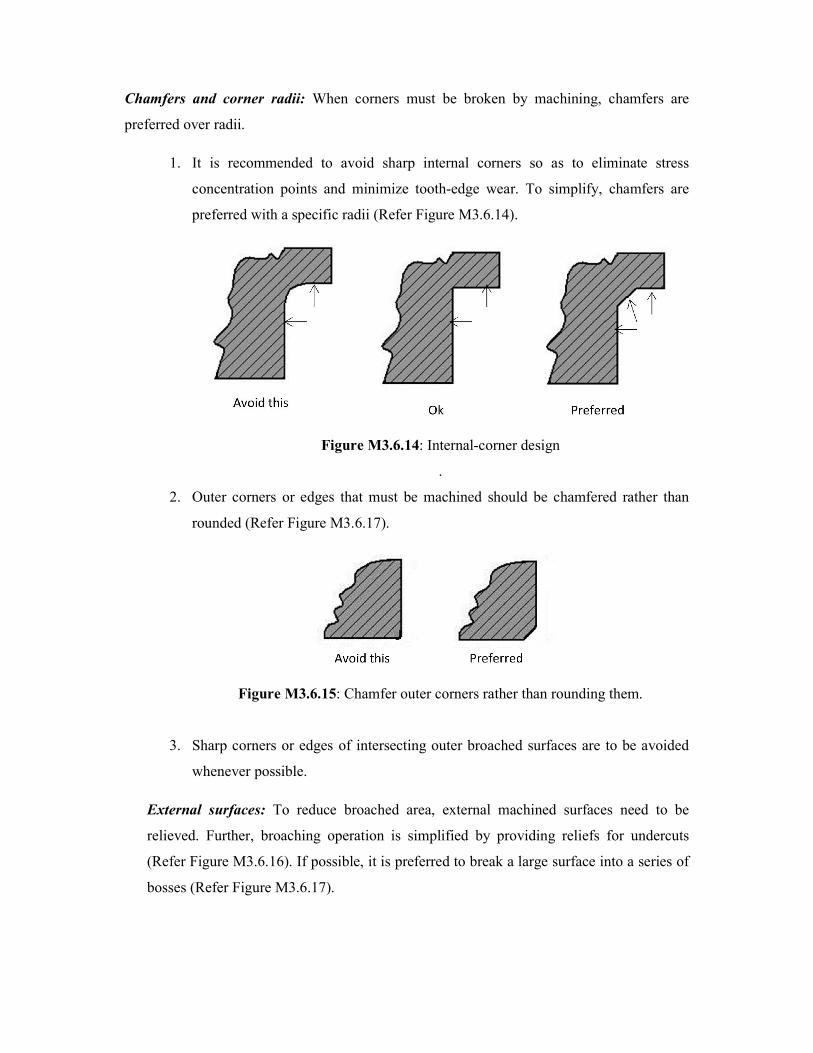
1. It is recommended to avoid sharp internal corners so as to eliminate stress
concentration points and minimize tooth-edge wear. To simplify, chamfers are
preferred with a specific radii (Refer Figure M3.6.14).
Figure M3.6.14: Internal-corner design
.
2. Outer corners or edges that must be machined should be chamfered rather than
rounded (Refer Figure M3.6.17).
Figure M3.6.15: Chamfer outer corners rather than rounding them.
3. Sharp corners or edges of intersecting outer broached surfaces are to be avoided
whenever possible.
External surfaces: To reduce broached area, external machined surfaces need to be
relieved. Further, broaching operation is simplified by providing reliefs for undercuts
(Refer Figure M3.6.16). If possible, it is preferred to break a large surface into a series of
bosses (Refer Figure M3.6.17).

Figure M3.6.16: Reliefs or undercuts in the corners simplify broaching of external surfaces.
Figure M3.6.17: Break large surfaces into series of bosses.
Undercuts: Sharp undercuts are to be avoided.
Burrs: Chamfers or reliefs are to be provided on the exit edge of the surface to be
broached to contain the burr produced and eliminate a deburring operation.
Unbalanced cuts: Tool deflections occur due to cross holes in the part and this has to be
avoided.

Dimensional factors
Factors which have significant role in tolerance control are uniformity of material,
consistency of datum faces (part-support faces, locating points, and clamping areas) and
strength of the part. In addition to these, other factors that affect tolerances and size
control are effectiveness of tool maintenance and re-sharpening, machinability of the
material, condition of the broaching machine, use of proper coolant, cutting speed and
proper design of the tool. Proper tool design is the most important factor in controlling
size and surface finish.
Recommended tolerances
Surface finish
Broached parts have high quality surface finish. Further, by employing good tool design
and applying proper coolant oils, a burnished finish quality can be obtained in good
machinability rated materials. Surface finishes expected under normal conditions are
provided in Table M3.6.1.
Flatness
A typical part of uniform section and sufficient strength to withstand cutting pressures
can be broached within 0.013 mm TIR (total indicator reading). A flatness of 0.025 mm is
recommended for most broached parts.
Parallelism
Parallelism of surfaces machined in the same cutting stroke should be within 0.025mm
TIR on good to fair machinability rated materials.
Squareness
For parts that can be fixtured and retained on true surfaces, a squareness of 0.025 mm TIR
is possible and tolerances of 0.08 mm can be obtained consistently under controlled
conditions in good-machinability rated materials.

Concentricity
Broaches usually will follow the pilot hole, and concentricity errors due to broach drift
should not exceed 0.025 to 0.05 mm for round or similarly shaped holes in good to fair
machinability rated materials.
Chamfers and Radii
Tolerances on chamfers and radii should be as liberal as possible. Radii under 0.8 mm
should have a minimum tolerance of 0.13 mm. 0.25 mm tolerance should be allowable on
larger sizes.