design, fabrication and testing of sandwich panel decking...
TRANSCRIPT

Design, fabrication and testing of sandwich panel decking for use
in road freight trailers
(Journal of Sandwich Structures and Materials)
Authors:
Joel Galos a,*, Michael Sutcliffe a, Golam Newaz b
a Department of Engineering, University of Cambridge, Trumpington Street,
Cambridge CB2 1PZ, UK
b Department of Engineering, Wayne State University, 5050 Anthony Wayne
Drive, Detroit, MI 48202, USA
* Corresponding Author. Tel: +44 (0)1223-332996. Email address: [email protected]
(J.L. Galos)
Abstract
This paper investigates the potential of sandwich structures in the novel application of road
freight trailer decking. Sandwich panels are developed to be lightweight replacements to
conventional birch plywood hardwood decking, which is the norm in European road freight
trailers. A tailored material selection process is used to identify the most advantageous
sandwich panel material combinations with respect to flexural properties and material cost.
Sandwich panels with woven glass fibre reinforced polyester and an end-grain balsa are found
to be the most advantageous material combination in terms of both raw material cost and
mechanical performance. These panels are fabricated using a single shot fabrication
technique and are approximately 30% lighter than conventional birch plywood trailer decking.
This weight saving corresponds to approximately 165 kg in a standard 13.6 m long European
road freight trailer. Three point bend testing has shown that these sandwich panels have
superior flexural strength and comparable flexural stiffness to birch plywood. Large panel
testing confirmed that these panels can withstand roughly four times the forklift wheel load
likely to be seen in-service. The shear properties of two grades of rigid end-grain balsa core
are also studied to illustrate the importance of using a higher density balsa core. Practical
considerations, such as joining and recyclability, for using sandwich panels in this application
are also discussed.
Keywords:
Sandwich design, applications, decking, road freight, balsa core, flexural testing.

Introduction
In road haulage the empty weight of a vehicle is a significant contributor to fuel consumption
and resulting CO2 emissions. Therefore, by reducing the empty mass of the trailer, the energy
efficiency of the vehicle as a whole can be improved [1]. Figure 1 shows the weight percentage
contributions of major structural components in a 13.6 m long flatbed road freight trailer,
commonly found in Europe and the United Kingdom (UK). It is evident that trailer decking,
which is typically hardwood-based, contributes a significant proportion of weight and is
therefore a good choice of sub-component to target for lightweighting. Using a lightweight deck
in trailer design is also significantly easier to implement practically compared to altering the
design of steel chassis beams or the running gear.
Figure 1. Typical weight breakdown of a standard 13.6 m long flatbed dry freight trailer (not including
trailer walls and body).
There are numerous kinds of deck material currently used in trailers; the foundation of the
majority of these is hardwood, either in a monolithic or layered ply form. The exposed surface
of the deck is typically covered in a non-slip, water-resistant material. For example; half lapped
keruing (hardwood) decking is often used in conjunction with an aluminium tread overlay.
Another typical example is birch plywood which is made from birch plies bonded with phenolic
adhesive and then covered with phenolic resin that is hot pressed to give a non-slip surface.
The geometry and mass characteristics of common existing deck materials are described in
Table 1. These decks are typically designed in accordance with ISO 1496: The specification
and testing of general cargo containers for general purposes [2].
Chassis beams
Running gear
Decking
Wheels
Suspension bracing Scrub plate

Table 1. Characteristics of existing hardwood based road freight deck materials typically used
throughout Europe and the UK. Total mass calculation assumes a deck area of 27 m2.
Deck material (Trade name)
Nominal
thickness
(mm)
Areal
mass
(kg/m2)
Total
mass
(kg)
Eucalyptus plywood (Lamideck) 28 18.2 491
Birch plywood (WISA-Trans) 30 21.0 567
The structural configuration of a lightweight trailer deck could take many potential forms,
including: monolithic panels, stiffened panels, sandwich panels and hybrid panels (e.g. fibre
reinforced foam-core sandwich panels). However, the highly cost-driven nature of trailer
construction, as well as the geometry of the conventional steel trailer chassis, makes sandwich
panels a strong candidate for use in this application. The use of a sandwich could help
increase flexural strength and rigidity, whilst simultaneously reducing weight [3]. Indeed, the
structure of conventional road freight semi-trailers is strikingly similar to pedestrian bridges,
where sandwich panel decks have been applied over steel beams with good success. The
success of sandwich panels in replacing plywood panels in the side walls of box-type road
freight trailers is also encouraging for their application to trailer decking.
Some work has been done to lightweight laminated oak wood trailer decks, which have been
the mainstay trailer deck material in North America for over four decades. For example, Havco
Products LLC produce laminated oak decks that are backed with glass fibre reinforced epoxy
to increase panel stiffness, while decreasing weight [4]. The composite stiffened oak panel is
reported to be about 90% stronger than a monolithic oak panel and this extra strength allows
for a reduction in thickness. The product has been tested in trailers for more than ten years
and has been commercially produced since 2000. Some research has also been conducted
on lightweighting oak trailer decking through the application of a sandwich panel composed of
ribbed fibre-reinforced plastic face sheets and a core of extruded aluminium tubes [5]. Both
glass fibre reinforced epoxy face sheets and carbon fibre reinforced epoxy face sheets were
considered. The panels were reported to be significantly stiffer than monolithic oak decking
and brought a weight saving of up to 68%.
The aim of this paper is to illustrate the potential of sandwich panels for use in road freight
trailer decking as a means of significantly reducing trailer weight without compromising
mechanical performance or chassis beam design. Through a close examination of the design

constraints specific to this application, a tailored material selection methodology is developed
which ensures that a balance between material cost and mechanical performance can be met.
The methodologies for sandwich optimisation developed by Steeves and Fleck [6] are also
applied here. Test specimens and larger demonstrator panels are built and tested in three
point bending to illustrate proof of concept.
Design constraints
It is desirable that sandwich panel decking is designed so that it can be fitted or retrofitted to
existing trailer chassis designs, so that existing chassis beams do not need to be modified.
Matching the dimensions of the replacement deck with the hardwood based materials will help
achieve this. Conventional hardwood decks are typically inserted between the transverse
beams and the top flange of the main longitudinal beams of the chassis, though they may also
be laid directly over the longitudinal beams. Hence, the nominal thickness of the deck should
be approximately 28 - 30 mm (Figure 2) and it should have comparable flexural properties to
hardwood based decking, particularly at a span length of approximately 450 mm, which is the
maximum typical spacing between transverse members in a standard 13.6 m trailer (Figure
3).
Figure 2. Spacing between the transverse and longitudinal beam members in a 13.6 m flatbed
chassis determines the required sandwich panel thickness. Image courtesy of SDC Trailers Ltd.

Figure 3. Plan view of the typical (TYP) spacing between the transverse members in a 13.6 m flatbed
chassis, which determines the required span length L subjected to three point bending. Image
courtesy of SDC Trailers Ltd.
In addition to loading and geometry requirements, the extremely cost-driven nature of the
construction of road freight trailers dictates that above all, sandwich panel trailer decking must
be cost competitive against conventional hardwood based decking. Discussions with industrial
partners indicate that the industry is willing to undertake a trial of new decking systems should
the relative material cost be less than two times that of existing hardwood decking and the
weight saving be significant (around 30%).
Material selection and detailed design
Material selection indices
The first step in sandwich panel design is to develop a material selection process for the face
sheets and core. To help achieve this, material selection software CES EduPack 2013 [7] is
used to identify potential material combinations that will allow the sandwich panel to match or
exceed the performance of hardwood in three point bending and at the same time be lighter.
Many different material combinations typically used in sandwich panel construction are
considered, along with other common monolithic materials for comparison. A list of the
different material combinations considered for use in the sandwich panel is provided in Table
2. All possible combinations of face sheet and core materials were considered. The resulting
material selection plot (Figure 4) is created based on a beam in three point bending. The plot
identifies the materials that match or exceed the performance of birch hardwood in three point
bending, by maximising stiffness M1 (Equation 1) and strength M2 (Equation 2) selection
indices as defined by Ashby [8].

𝑀1 = 𝐸𝑏
1/2
𝜌
(1)
𝑀2 = 𝜎𝑏
2/3
𝜌
(2)
Table 2. Face sheet and structural core materials considered in the sandwich panel
material selection process.
Potential face sheet materials Potential core materials
Woven E-glass fibre / polyester (GFRP) End-grain balsa wood
E-glass fibre / epoxy laminate Nomex honeycomb
Carbon fibre / epoxy laminate Polypropylene (PP) honeycomb
Aluminium PP foam
Hardwood Aluminium honeycomb
Aluminium foam
Polycarbonate (PC) foam
Polyvinylchloride (PVC) foam
Phenolic foam
Polyurethane (PU) foam
Figure 4. Material selection plot for a beam in three point bending developed in CES Edupack
2013 [7]. Orange and yellow markers indicate sandwich panels that match or exceed the performance
of birch hardwood (shown in green) in three point bending.

During the material selection process it was assumed that the sandwich panel face sheet
thickness varied from 1 mm (with a 26 mm core) to 4 mm (with a 20 mm core). This was done
to ensure that the sandwich panel has a nominal thickness of 28 mm to match the thickness
of typical birch plywood decking. A nominal thickness of 28 mm will also allow enough room
for a non-slip surface coating to be applied.
Detailed design
Because material selection here is largely driven by cost, many of the sandwich panel material
combinations that are common in other industries, such as aerospace, are far less feasible for
use here, despite their superior mechanical properties. The materials identified as being
acceptable from the material selection plot (Figure 4) are analysed in terms of their relative
cost and relative mass, and the cheapest successful material combinations are shown in Table
3. The sandwich panel material combinations not shown in Table 3 are considered to be
unsuitable for use here since they do not meet the weight and mechanical performance
requirements. The exact minimum face sheet thicknesses tmin required to match the stiffness
and strength of birch plywood are found by considering the minimum collapse load and flexural
rigidity of each of the sandwich panels, using average material properties provided in CES
Edupack 2013 [7]. The minimum collapse load is determined by considering competing
collapse modes (Appendix A). The results of this procedure are summarised in Table 3.
Table 3. Minimum face sheet thickness and failure modes for various sandwich panels (28 mm total
thickness) with either woven GFRP or aluminium face sheets. Symbols correspond to those shown in
Figure 5. Specific gravity of structural cores shown in brackets.
Material combination
tmin
(mm)
Design
driver Collapse mode
○ GFRP - end-grain (0.2) balsa 2.4 Stiffness Core shear
△ GFRP - PP (0.6) foam 2.3 Stiffness Elastic indentation
□ GFRP - PVC (0.3) foam 2.3 Stiffness Elastic indentation
▽ GFRP - PU (0.3) foam 2.5 Strength Elastic indentation
● Aluminium - end-grain (0.2) balsa 1.2 Strength Face yield
▲ Aluminium - PP (0.6) foam 1.2 Strength Face yield
■ Aluminium - PVC (0.3) foam 1.2 Strength Face yield
▼ Aluminium - PU (0.3) foam 1.7 Strength Elastic indentation
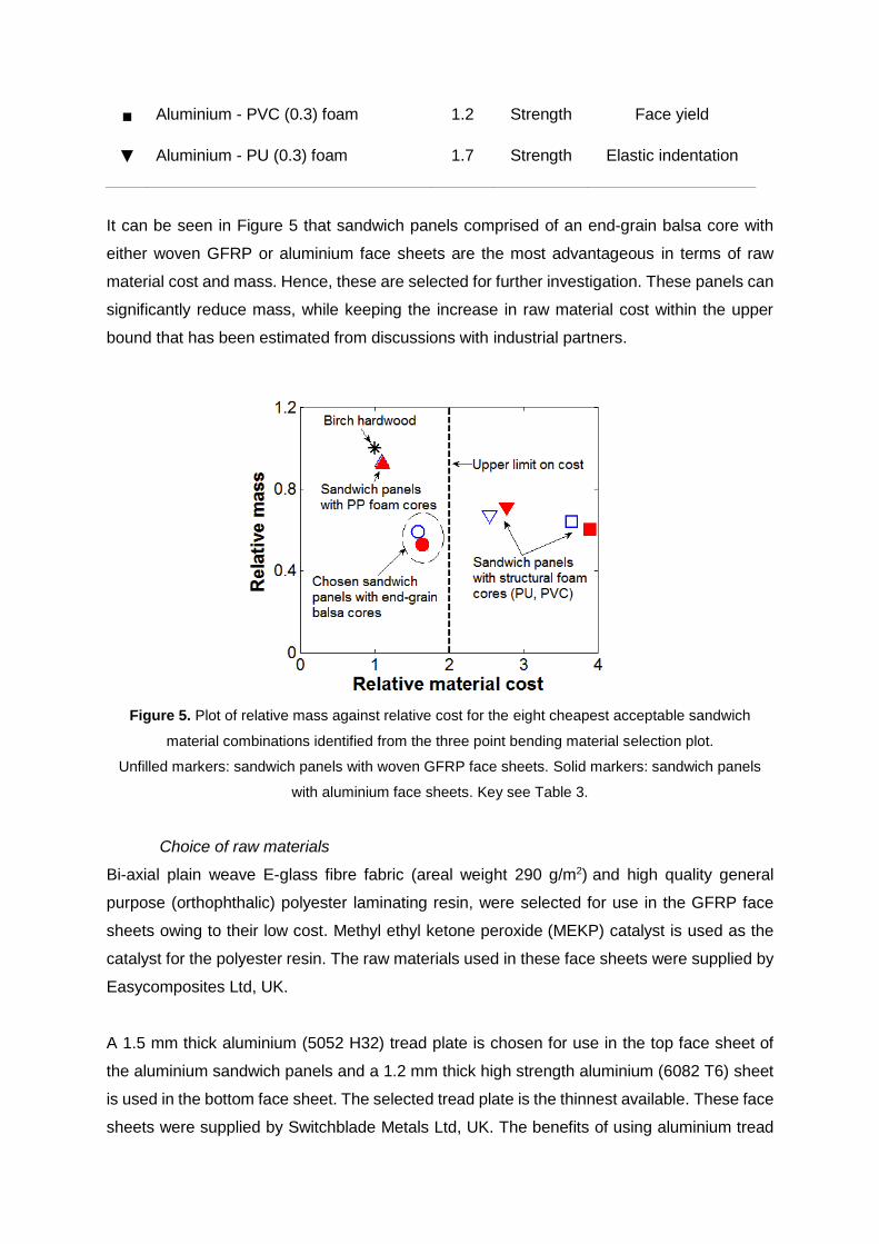
It can be seen in Figure 5 that sandwich panels comprised of an end-grain balsa core with
either woven GFRP or aluminium face sheets are the most advantageous in terms of raw
material cost and mass. Hence, these are selected for further investigation. These panels can
significantly reduce mass, while keeping the increase in raw material cost within the upper
bound that has been estimated from discussions with industrial partners.
Figure 5. Plot of relative mass against relative cost for the eight cheapest acceptable sandwich
material combinations identified from the three point bending material selection plot.
Unfilled markers: sandwich panels with woven GFRP face sheets. Solid markers: sandwich panels
with aluminium face sheets. Key see Table 3.
Choice of raw materials
Bi-axial plain weave E-glass fibre fabric (areal weight 290 g/m2) and high quality general
purpose (orthophthalic) polyester laminating resin, were selected for use in the GFRP face
sheets owing to their low cost. Methyl ethyl ketone peroxide (MEKP) catalyst is used as the
catalyst for the polyester resin. The raw materials used in these face sheets were supplied by
Easycomposites Ltd, UK.
A 1.5 mm thick aluminium (5052 H32) tread plate is chosen for use in the top face sheet of
the aluminium sandwich panels and a 1.2 mm thick high strength aluminium (6082 T6) sheet
is used in the bottom face sheet. The selected tread plate is the thinnest available. These face
sheets were supplied by Switchblade Metals Ltd, UK. The benefits of using aluminium tread

plate as the top face sheet of sandwich panels in mass transport applications have been well
documented [9].
Rigid end-grain balsa core sheets (Figure 6), comprised of many constituent blocks of balsa
bonded together with polyvinyl acetate (PVA) adhesive, were used in all sandwich panels and
were supplied by Gaugler & Lutz oHG, Germany. Material properties of the chosen face sheet
materials and end-grain balsa core are shown in Tables 4 and 5 respectively. Table 5 shows
the relevant material properties of three commercially available end-grain balsa cores taken
from the manufacturer data sheet [10]. Both the intermediate density core (tradename Baltek
SB.100) and the higher density core (tradename Baltek SB.150) are selected for investigation.
Figure 6. Baltek SB.100 rigid end-grain balsa core sheet comprised of many constituent blocks
bonded together with PVA adhesive.
Table 4. Material properties of selected face sheet materials. Flexural properties determined through
flexural testing with span length = 120 mm, loading/support roller diameter = 19 mm, specimen
length = 160 mm, specimen width = 25 mm and test speed = 5 mm/min. (Minimum of five specimens
tested in every case and average values reported). Flexural stiffness determined from the initial slope
in the load-displacement curve.
Face sheet material
Nominal
thickness
(mm)
Measured
density
(kg/m3)
Ultimate
flexural
strength
(MPa)
Flexural
stiffness
(GPa)
Seven ply bi-axial weave GFRP 2.1 1,900 370 22
Aluminium tread plate (5052 H32) 1.5 2,700 360 65
Aluminium sheet (6082 T6) 1.2 2,700 490 77
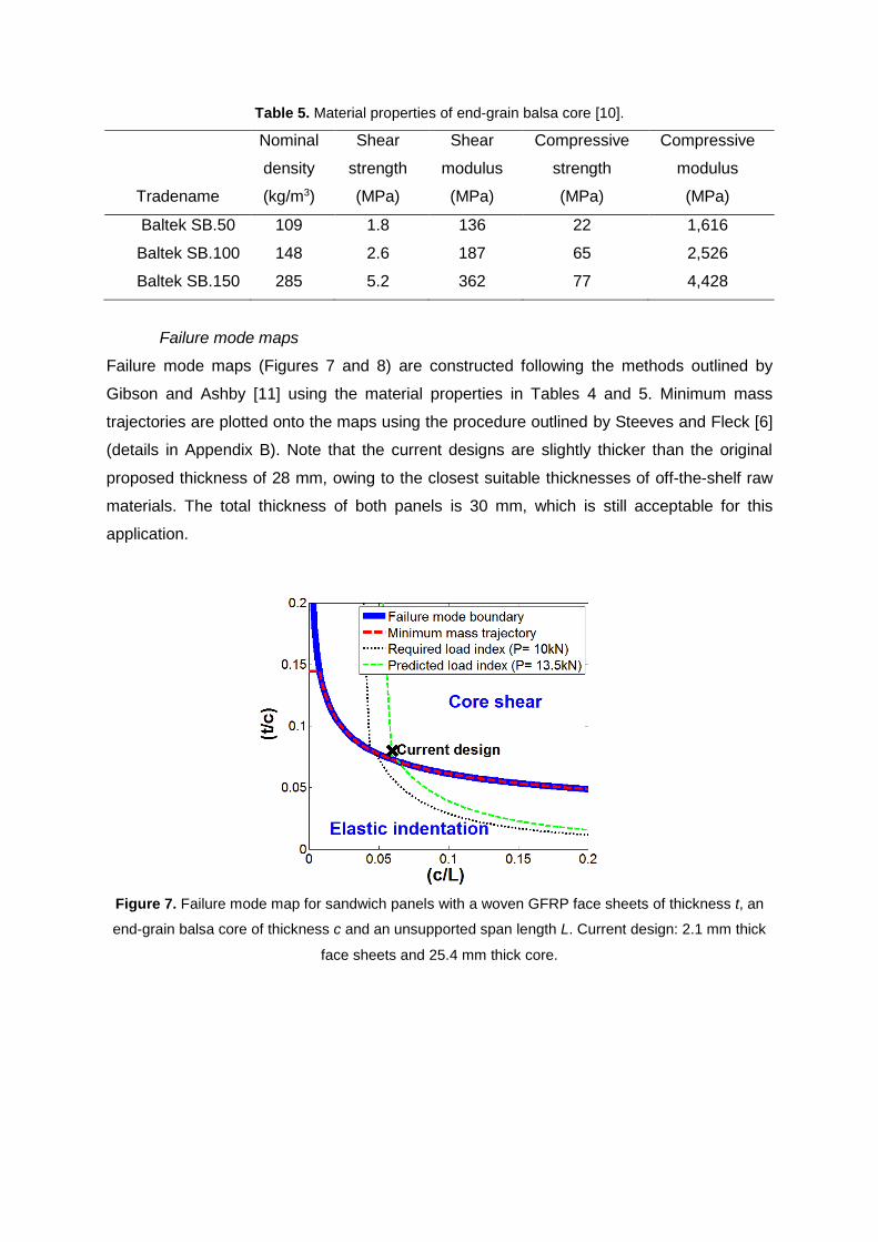
Table 5. Material properties of end-grain balsa core [10].
Tradename
Nominal
density
(kg/m3)
Shear
strength
(MPa)
Shear
modulus
(MPa)
Compressive
strength
(MPa)
Compressive
modulus
(MPa)
Baltek SB.50 109 1.8 136 22 1,616
Baltek SB.100 148 2.6 187 65 2,526
Baltek SB.150 285 5.2 362 77 4,428
Failure mode maps
Failure mode maps (Figures 7 and 8) are constructed following the methods outlined by
Gibson and Ashby [11] using the material properties in Tables 4 and 5. Minimum mass
trajectories are plotted onto the maps using the procedure outlined by Steeves and Fleck [6]
(details in Appendix B). Note that the current designs are slightly thicker than the original
proposed thickness of 28 mm, owing to the closest suitable thicknesses of off-the-shelf raw
materials. The total thickness of both panels is 30 mm, which is still acceptable for this
application.
Figure 7. Failure mode map for sandwich panels with a woven GFRP face sheets of thickness t, an
end-grain balsa core of thickness c and an unsupported span length L. Current design: 2.1 mm thick
face sheets and 25.4 mm thick core.

Figure 8. Failure mode map for sandwich panels with aluminium face sheets of thickness t, an end-
grain balsa core of thickness c and an unsupported span length L. Current design: 1.5 mm thick top
face sheet (tread plate), 1.2 mm bottom face sheet and 25.4 mm thick core.
Panel fabrication
There are several potential strategies that could be used to fabricate the two selected
sandwich panels, particularly with respect to the woven GFRP sandwich panel. This panel can
be manufactured with a single shot process where the face sheets are cured and bonded to
the balsa core simultaneously, or they could be manufactured by a multi-stage process by
which the face sheets are cured then bonded to the core, or indeed a combination of these
strategies known as a co-bonding process could be used. Both the multi-stage process and
the single shot process are chosen for further investigation as they are the most likely to be
implemented practically. However, should these sandwich panels be mass produced for
commercial use, a single shot manufacturing process would most likely be more desirable as
it removes the need for costly structural adhesives, helping to keep material costs to a
minimum.
Woven GFRP panels are fabricated using a wet hand lay-up process and left to cure under
heat lamps. It was found that seven layers of 290 g/m2 woven glass fibre fabric produced a
desirable average thickness of 2.1 mm. Care was taken during the wet hand lay-up process
to thoroughly roll the polyester resin into the dry fabric to minimise the number of voids, though
the inherent lack of pressure in the process results in voids being present in the final laminate
(Figure 9 (b)). Whilst a vacuum infusion process would likely significantly reduce the void
volume fraction, the increased costs associated with this process make it less desirable for
use here. The panels made with the single shot process are shown in Figure 9.

(a) (b)
Figure 9. (a) Woven GFRP-balsa (SB.150) sandwich panel manufactured with a single shot process
(2.1 mm thick face sheets and 25.4 mm thick core) and with a non-slip polyamine epoxy coating
applied. (b) Micrograph of GFRP face sheet used in sandwich panel construction, showing the
presence of numerous voids introduced during the wet hand lay-up of the face sheets (typical cross
section inset).
During the single shot fabrication process, the end-grain balsa core is laid directly over the
bottom face sheet before the resin cures and the top face sheet is subsequently laid up over
the core. In the multi-stage fabrication process, on the other hand, cured GFRP panels are
bonded to the end-grain balsa core using methacrylate adhesive (VuduGlu VM100), which
typically has good bond strength with GFRP (Figure 10 (a)). The surface of the GFRP to be
bonded is cleaned with distilled water to help improve the adhesion of the face sheet to the
core.
Due to long lead times associated with acquiring 25.4 mm thick rigid SB.100 end-grain balsa
core, two pieces of 12.7 mm thick core are used in replacement of the 25.4 mm thick core.
The two 12.7 mm thick cores are bonded together with a structural epoxy adhesive
(Permabond ET515). The superior mechanical properties of the adhesive compared to the
core helps to ensure that this has minimal impact on overall panel performance. Panels that
were constructed with the denser SB.150 core all used a 25.4 mm thick rigid core that did not
require this additional fabrication step.
The sandwich panels with aluminium face sheets (Figure 10 (b)) are fabricated by bonding the
face sheets to the core using either methacrylate adhesive (VuduGlu VM100) or structural
epoxy adhesive (Permabond ET515). Prior to bonding, the surface of the aluminium to be
bonded is roughened with grit paper then degreased with acetone to help improve adhesion
of the face sheet to the core. The weight characteristics of all SB.150 sandwich panels are

compared to birch plywood in Table 6, and it can be seen that the single shot GFRP panel
provides the greatest weight saving benefit.
(a) (b)
Figure 10. (a) Woven GFRP-balsa (SB.150) sandwich panel (2.1 mm thick face sheets and 25.4 mm
thick core). (b) Aluminium-balsa (SB.150) sandwich panel (1.5 mm thick 5052 H32 tread plate top
face sheet, 1.2 mm thick 6082 T6 bottom face sheet and 25.4 mm thick SB.150 core). Panels are
constructed by bonding the face sheets to the core with methacrylate adhesive.
Table 6. Comparison of the weight characteristics of sandwich panels with higher density (SB.150)
end-grain balsa cores to birch plywood decking. Total mass calculation assumes a deck area of
27 m2.
Deck type
Density
(kg/m3)
Nominal
thickness
(mm)
Areal
mass
(kg/m2)
Total
mass
(kg)
Weight
saving
(%)
Birch plywood 700 30 21.0 567 0
GFRP-balsa SB.150 (single shot) 498 30 14.9 403 29
GFRP-balsa SB.150 (methacrylate) 515 31 16.0 431 24
Al-balsa SB.150 (methacrylate) 529 30 15.9 428 24
Mechanical testing
Three point bending tests are performed to determine the flexural stiffness and strength of the
fabricated sandwich panels, as well as conventional birch plywood. The test set up and
specimen parameters are shown in Figure 11. A span to thickness ratio of approximately 15/1
is used to help ensure that the specimens will fail in bending. The span length of 428 mm used
in testing was the maximum allowable span length given the fixture and test machine used.
This is close to the 450 mm span length that is typically used in a standard 13.6 m UK road
freight trailer. All three point bend tests are performed on an Instron 5500R Universal Test

Machine using a test speed of 5 mm/min. A laser displacement sensor is used to capture
displacement at the mid-span of the bottom face sheet.
Figure 11. Nominal specimen dimensions and test parameters used in flexural testing, with an
applied load P. Test speed = 5 mm/min.
Panel testing on larger demonstrator panels is also performed to simulate loading from a
forklift wheel that is commonly seen in-service. Large panels with dimensions of
550 x 400 x 30 mm were simply supported between two rollers (diameter 76 mm), providing
an unsupported span length of 500 mm as shown in Figure 12. The panels were loaded
through a rubber pad in the centre of the mid-span over a contact area of 180 x 80 mm. The
contact patch area of the rubber pad simulates a forklift wheel and is chosen as per the
recommendations in ISO 1496: The specification and testing of general cargo containers for
general purposes [2]. A laser displacement sensor is also used in this test to determine the
displacement at the centre underside of the panel.
Figure 12. Panel testing setup with simulated forklift wheel contact. Test speed = 5 mm/min.

Results and discussion
Typical load-displacement curves for the sandwich panels with SB.150 end-grain balsa cores
tested in three point bending are shown in Figure 13, along with load-displacement curves of
conventional birch plywood decking of the same nominal dimensions. Figure 14 plots the
mean ultimate load and mean flexural modulus for all of the sandwich panel specimens tested.
The flexural modulus is calculated from the gradient of the initial linear portion of the load-
displacement curve obtained during testing. It is evident from Figures 13 and 14 that the
sandwich panels with high density (SB.150) cores generally have superior flexural strength
and comparable flexural stiffness in comparison to birch plywood. The majority of the sandwich
panel specimens with SB.100 grade cores failed prematurely in core shear and did not exhibit
the desired flexural properties. The sandwich panel specimens with GFRP face sheets
typically failed in core shear (Figure 15 (a)), while the methacrylate bonded aluminium
sandwich panels typically failed through face sheet yielding, followed by core shear failure
(Figure 15 (b)), as predicted by the failure mode maps (Figures 7 and 8). On the other hand,
the aluminium sandwich panel specimens bonded with epoxy adhesive exhibited premature
debonding of the face sheets from the core.
Figure 13. Typical load-displacement curves of the sandwich panels with SB.150 end-grain balsa
cores in three point bending, compared to birch plywood.

Figure 14. (a) Mean ultimate load and (b) mean flexural modulus of the sandwich panels in three
point bending, compared to birch plywood. Error bars indicate standard deviation.
(a) (b)
Figure 15. (a) Core shear failure observed in GFRP-balsa (SB.150) sandwich panels. (b) Face sheet
yielding, followed by core shear failure observed in methacrylate bonded aluminium-balsa (SB.150)
sandwich panels.
The load-displacement curves obtained from large panel testing of demonstrator sandwich
panels and birch plywood of the same dimensions are shown in Figure 16. It is evident that
the GFRP-balsa (SB.150) panel once again had superior strength and comparable stiffness
in comparison to birch plywood. This result is encouraging since this application is more
strength than stiffness limited. It is also apparent from Figure 16 that the GFRP-balsa (SB.150)
sandwich panel can withstand approximately four times the forklift wheel load of 12.25 kN that
is commonly seen in-service. This panel ultimately failed at the top face sheet (Figure 17),
which is in compression, at a load of approximately in 45 kN. In contrast to this, the
methacrylate bonded aluminium-balsa (SB.150) sandwich panel failed prematurely at
approximately 12 kN as a result of face sheet debonding.

Figure 16. Load-displacement curves obtained from large panel (500 x 400 x 30 mm) testing with
loading through a simulated forklift wheel (contact area 180 x 80 mm). The 5 tonne forklift wheel load
is equivalent to 12.25 kN applied through a single wheel in a four wheel forklift.
Figure 17. Top face sheet failure observed during large panel testing of 30 mm thick woven GFRP-
balsa (SB.150) (single shot) sandwich panel with non-slip coating. Failure propagates along one edge
of the rubber pad that simulates a forklift wheel.
The premature core shear failures in the intermediate density balsa (SB.100) sandwich panel
specimens can be attributed to the presence of lower density constituent pieces of end-grain
balsa that are found within a single sheet of rigid core (Figure 18). It is well known that the
mechanical properties of balsa vary with density [12–14]. This was confirmed by determining
the shear properties of the end-grain core using a novel ‘hole-punch’ test, described in

Appendix C. Results of the shear testing (Figure 19) show the significantly reduced shear
strength and stiffness of the lower density constituent blocks present within a single sheet of
core material. This is most likely to be the cause of the adverse flexural properties observed
in many of the SB.100 sandwich panel specimens. This problem was overcome by using the
higher density SB.150 end-grain balsa core, which has been shown to have superior shear
properties here and by Osei-Antwi et al. [14].
Figure 18. Histogram of the density of constituent blocks within single sheets of rigid Baltek SB.100
and SB.150 end-grain balsa core. Medians and standard deviations (S.D.) are also shown.
Figure 19. Variations in (a) Shear strength and (b) nominal shear modulus, with density of end-grain
balsa core used in sandwich panel construction. Properties determined through ‘hole-punch’ test
(described in Appendix C).

While cost and mechanical performance are the two main concerns that sandwich panel
decking needs to satisfy to be used successfully in this application, there are other practical
issues that need to be considered. For example, safety dictates that it is desirable to have the
exposed surface of the GFRP sandwich panel deck covered or treated with a non-slip coating.
An abrasion resistant polyamine epoxy coating, commonly spray-applied to bridge decks and
helidecks, should work well in this application and was successfully applied to the
demonstrator panel (Figure 17).
Since road freight trailers are generally returned to trailer manufacturers for recycling at the
end of their service life, the recyclability of the sandwich panel constituent materials also needs
to be taken into consideration. This issue of sustainability supports the choice of balsa as a
core material over a polymer foam material. While aluminium face sheets are generally more
recyclable than GFRP face sheets, the recyclability of fibre reinforced plastics is a focus of
much on-going research and is expected to improve within the coming years.
Another important consideration in the application of sandwich panel decking to road freight
trailers is the method of joining. Mechanical fastening is the most common form of joining
hardwood decking to the trailer beams, though structural adhesives have been successfully
used in the past and these can also help to reduce weight [15]. Structural adhesives are the
most attractive way to bond a lightweight composite deck to steel trailer beams, though there
are some issues that need to be addressed, including: surface preparation of chassis beams,
curing time and curing temperature. Nevertheless, these issues have been successfully
overcome in other comparable industries (e.g. bridge construction). In addition to these issues,
the operating temperature of certain adhesives could be another limiting factor. For example,
epoxy adhesives generally have a glass transition temperature of around 50°C, beyond which
their adhesive strength is significantly lower. Hence, adhesively bonded trailer decking could
be unsuitable for use in extremely hot environments where prolonged sun exposure is likely.
Finally, it is worth noting that fatigue and impact performance of trailer decking will also require
some attention, but this is outside the scope of the current work.
Conclusions
Applying sandwich panels to road freight trailer decking in replacement of conventional
hardwood decking has the potential to significantly reduce empty trailer weight, without
compromising the structural design of the trailer chassis. The weight saving potential of
sandwich panels in this application does not justify a large increase in material cost. Hence
cost, as well as flexural properties, drive material selection in sandwich design. Sandwich
panels with woven GFRP face sheets, and a higher density end-grain balsa core satisfy this

material selection criterion the most effectively. The chosen sandwich panels presented here
are approximately 30% lighter than conventional birch plywood trailer decking, which
corresponds to a weight saving of approximately 165 kg in a standard 13.6 m long European
flatbed trailer.
Premature core shear failure during three point bend testing is likely to occur in the sandwich
panels, should the end-grain balsa core not be sufficiently dense. Hence, in this application it
is recommended to use the highest grade (densest) end-grain core available, though there is
a slight weight penalty associated with the selection of the densest core. Some practical issues
(e.g. the method of joining panels to steel chassis beams) will need to be overcome before
sandwich panels can be effectively used in this application. However, the majority of these
issues have been successfully resolved in other industries, meaning there should be no
significant technical barriers to overcome in applying sandwich panels to road freight trailers.
Material and fabrication costs are the main obstacles to the practical uptake of these structures
in road freight trailers.
Acknowledgements
The authors would like to acknowledge the financial support from the members of the Centre
for Sustainable Road Freight and from the Engineering and Physical Sciences Research
Council (Grant Reference EP/K00915X/1). The authors are also grateful to the help and
guidance in sandwich panel fabrication provided by Paul Johns and Nick Warrior at the
University of Nottingham, as well as for the use of the manufacturing facilities at the University
of Nottingham. Finally, the assistance of Alan Heaver and Carlos Pascal at the University of
Cambridge in mechanical testing is gratefully acknowledged.
References
1. Galos J, Sutcliffe M, Cebon D, Piecyk M, Greening P. Reducing the energy consumption of heavy goods vehicles through the application of lightweight trailers: Fleet case studies. Transp Res Part D Transp Environ. Elsevier Ltd; 2015; 41:40–9.
2. ISO 1496-1: Series 1 freight containers - specification and testing - part 1, general cargo containers. Washington DC: International Organization for Standardization, 1990.
3. Zenkert D. An introduction to sandwich construction. 1st ed. London: Emas Publishing, 1997.

4. JEC Group. Composite flooring makes for versatile trailers, http://www.jeccomposites.com/news/composites-news/composite-flooring-makes-versatile-trailers (2011, accessed 28 September 2015).
5. Shoukry SN, William GW, Prucz JC, Evans TH. Application of composite sandwich panels in heavy vehicle systems. Proceeedings of 18th International Conference on Composites or Nano Engineering. Anchorage, Alaska; 2010. p. 363–4.
6. Steeves C, Fleck N. Material selection in sandwich beam construction. Scr Mater. 2004 May; 50(10):1335–9.
7. Granta Design Limited. CES EduPack 2013 Software. Cambridge, UK, 2013.
8. Ashby M. Material selection in mechanical design. 3rd ed. Oxford: Elsevier; 2005.
9. Vaiday U. Composites for automotive, truck and mass transit: materials, design, manufacturing. Lancaster, US: DEStech Publications, 2011.
10. 3AComposites Core Materials. Baltek SB Data Sheet, http://www.airexbaltekbanova.com/baltek-sb-balsa.html (2014, accessed 31 July 2014).
11. Ashby M, Evans T, Fleck NA, Hutchinson JW, Wadley HNG, Gibson LJ. Metal foams: a design guide. 1st ed. Burlington: Elsevier Science, 2000.
12. Easterling KE, Harrysson R, Gibson LJ, Ashby MF. On the mechanics of balsa and other woods. Proc R Soc A Math Phys Eng Sci. 1982; 383(1784):31–41.
13. Borrega M, Gibson LJ. Mechanics of balsa (Ochroma pyramidale) wood. Mech Mater. Elsevier Ltd; 2015; 84:75–90.
14. Osei-Antwi M, De Castro J, Vassilopoulos AP, Keller T. Shear mechanical characterization of balsa wood as core material of composite sandwich panels. Constr Build Mater. 2013; 41:231–8.
15. Noonan B. Assembly Magazine. Adhesives for trailer assembly p. 38–41, http://www.assemblymag.com/articles/86655-adhesives-for-trailer-assembly (2009, accessed 31 July 2014).
Appendices
Appendix A. Flexural rigidity and failure collapse loads
Nomenclature
b = panel width,
c = core thickness,
D = Flexural rigidity,
E = Young’s modulus,
M = panel mass,
M1 = stiffness selection index,
Subscripts
b = material property in bending,
c = core material property,
f = face sheet material property,
CS = core shear,
FY = face yield,
ID = ductile indentation,

M2 = strength selection index,
L = span length,
P = applied load,
t = face sheet thickness,
𝜌 = density,
𝜏 = shear strength,
𝜎 = yield stress.
IE = elastic indentation.
Flexural rigidity of each sandwich panel, calculated as per [11]:
𝐷 = 𝐸𝑓𝑏𝑡(𝑡 + 𝑐)2
2+
𝐸𝑓𝑏𝑡3
6+
𝐸𝑐𝑏𝑐3
12 (3)
Core shear failure occurs when the shear strength of the core is exceeded.
𝑃𝐶𝑆 = 2𝑏(𝑡 + 𝑐)𝜏𝑐 (4)
Face yielding occurs when the axial stress in the face sheet reaches the yield
strength of the material.
𝑃𝐹𝑌 =4𝑏𝑡(𝑡 + 𝑐)𝜎𝑓
𝐿 (5)
Ductile indentation occurs when the face sheets are assumed to form plastic hinges
at the boundaries of the indentation region.
𝑃𝐼𝐷 = 2𝑏𝑡(𝜎𝑐𝜎𝑓)1/2 (6)
Elastic indentation occurs when the face sheets remain elastic while the core yields
plastically. In this case, the face sheets behave as a beam column upon a non-linear
foundation, which is the core.
𝑃𝐼𝐸 = 𝑏𝑡 (𝜋2(𝑡 + 𝑐)𝐸𝑓𝜎𝑓
2
3𝐿)
1/3
(7)

Appendix B. Failure mode map methodology
In order to construct sandwich failure mode maps, it is first necessary to define the following
non-dimensional material and geometric parameters:
𝑡̅ =𝑡
𝑐; 𝑐̅ =
𝑐
𝐿; �̅� =
𝜎𝑐
𝜎𝑓; �̅� =
𝜏𝑐
𝜎𝑓; �̅� =
𝐸𝑐
𝜎𝑓; 𝑎𝑛𝑑 �̅� =
𝜌𝑐
𝜌𝑓 (8)
A non-dimensional load index �̂� is defined as
�̂� =𝑃
𝑏𝐿𝜎𝑓 (9)
The mass of the sandwich beam M is calculated as
𝑀 = 𝑏𝐿(2𝑡𝜌𝑓 + 𝑐𝜌𝑐) (10)
and the non-dimensional mass index �̂� is defined by substituting the non-dimensional
parameters from Equation 8 into Equations 9 and 10.
�̂� =𝑀
𝑏𝐿2𝜌𝑓= 𝑐̅(2𝑡̅ + �̅�) (11)
The failure loads of the competing collapse modes (Equations 4 to 7) can also be non-
dimensionalised in a similar fashion, as shown in Equations 12 to 15.
�̂�𝐶𝑆 = 2�̅�(𝑡̅ + 1)𝑐 ̅ (12)
�̂�𝑀 = 4𝑡̅(𝑡̅ + 1)𝑐̅2 (13)
�̂�𝐼𝐷 = 2𝑡𝑐̅̅ �̅�1/2 (14)
�̂�𝐼𝐸 = (𝜋2�̅�2�̅�
3)
13
𝑡̅(𝑡̅ + 1)1/3𝑐̅4/3 (15)
Having defined the non-dimensional load indices, failure mode maps can be constructed by
first determining the weakest and therefore active failure mode which then gives the dominant
failure regimes. The failure mode maps can also be used to optimise the sandwich panel
design. The optimisation strategy outlined by Steeves and Fleck [6], finds values of 𝑡̅ and 𝑐̅
that minimise the mass index �̂� for a given load index �̂�. The trajectory of the minimum mass
design then typically lies along the failure mode boundaries, although it can also lie with the
elastic indentation domain and the face yield domain. Within the elastic indentation domain,
the optimal value of 𝑡̅ is given by Equation 16.
𝑡̅ =3�̅�
2(1 − 2�̅�) (16)
Within the face yield domain, the optimal value of 𝑡̅ is given by Equation 17.
𝑡̅ =�̅�
2(1 − �̅�) (17)
Appendix C. Balsa shear testing
In order to determine the shear properties of the end-grain balsa used in sandwich panel
construction, a novel 'hole-punch' style of test was used, a schematic of which is shown in
Figure 20. Here the shear strength 𝜏 is calculated by 𝜏 = P/A, where A is the specimen
thickness multiplied by the circumference of the cylindrical punch. Since the cylindrical punch
pushes an almost perfectly circular piece of balsa out of the test specimen, this is considered
to be a reasonable way of determining the shear strength of balsa. The test method also allows
for a comparative study of balsa shear modulus. A nominal shear modulus is determined from
the initial slope in the load-displacement curve produced during the testing. However, since
the elastic shear strain zone is not well defined here, the resultant value of shear modulus is
taken to be nominal, rather than absolute. The nominal shear modulus Gnominal is found with
the initial slope m in the load displacement curve, the whole punch diameter d and A (Equation
18).
G𝑛𝑜𝑚𝑖𝑛𝑎𝑙 =𝑚𝑑
𝐴 (18)

Figure 20. Schematic of 'hole-punch' test used to determine the apparent properties of constituent
end-grain balsa blocks.
Appendix D. Supplementary material
Supplementary data associated with this article can be found online at: (DOI TBD)