design, construction and tests of a 10 mev linac for ... · design, construction and te sts of a 10...
TRANSCRIPT

DESIGN, CONSTRUCTION AND TESTS OF A 10 MeV LINAC FOR POLYMER RADIATION PROCESSING *
Guangyao Feng, Yuanji Pei, Lin Wang, Shancai Zhang, Yilin Hong, Lei Shang, Kai Jin, Xiangqi Wang, Chenggui Yao, National Synchrotron Radiation Laboratory, University of Science and
Technology of China, Hefei, Anhui, 230029, P. R. China
Abstract In china, polymer radiation processing has become one
of the most important processing industries. Electron beam accelerator or radioactive source is usually used as radiation processing source. For radiation crosslinking application, physical design, construction and testing of a electron beam facility is introduced because of it’s much higher dose rate and efficiency. Main part of this facility is a 10MeV traveling wave electron linac with constant impedance accelerating structure. It is the first electron beam facility designed for polymer radiation processing by National Synchrotron Radiation Laboratory (NSRL) in China. In the paper, a start to end simulation is finished to optimize electron beam dynamics in the linac. Measurement results of some subassemblies are presented. The linac construction has been finished just now. Testing experiments prove that the facility can work well for radiation crosslinking application.
INTRODUCTION As we know, charged particle accelerator can be
applied in many fields, Such as high energy particles experiments, synchrotron radiation research. It also can be applied in industry, agriculture, medicine[1], etc. Commonly, industrial irradiation accelerators include dynamitron, induction accelerator, insulating transformer accelerator, linear accelerator, rhodotron, etc. For industrial applying accelerator, considering the security against radiation, energy gain is usually limited not higher than 10MeV. In China, polymeric materials radiation processing has become one of the important processing industries. As a rule, there are four polymeric materials radiation effects including radiation crosslinking, radiation induced grafting, radiation polymerisation and radiation degradation. About 90% radiation processing products are obtained by radiation crosslinking in China now. In the paper, design of 10MeV traveling wave electron linac with constant impedance accelerating structure is introduced, which will be applied for radiation crosslinking for University of Science and Technology of China (USTC) Chuangxin Stock Limited Company. Measurement results of some subassemblies are presented. The linac construction has been finished recently. Testing experiments prove that the facility can work well for radiation crosslinking application.
SUBSYSTEMS AND BEAM DYNAMICS
Main parts of the 10MeV electron linac include DC electron gun, disk-loaded periodic structures, RF power supply, wave guides, focusing solenoids, vacuum system, control system, orbit correction system and beam diagnoses system, etc. Figuer1 shows layout of the linac. In order to satisfy the industrial requirement, Table1 gives main parameters of the machine. This facility works in S band and the RF frequency is 2856MHz.
Figure 1: Layout of the 10MeV linac.
Table 1: Main Parameters of The Linac
Beam energy (MeV) 8-10
Beam current power (kW) ~10
Pulse current (mA) 300-400
Energy spread <±5%
Pulse repeat frequency (Hz) 100-200
Beam size at the window (mm) Φ10-15
Number of klystron 1
Klystron output power (MW) 5.4
Output pulse wide (μs) 13
RF frequency (MHz) 2856
Accelerating type Constant impedance
Dose uniformity <5%
Dc Electron Gun The electron gun is a grid control DC gun[2,3], which
can generate 45keV electron beam. Considering the electron capture efficiency in the linac, beam pulse current emitted from the gun is about 700-900mA.
___________________________________________
*Work supported by National Science Foundation of China (10575096)#[email protected]
TU6PFP002 Proceedings of PAC09, Vancouver, BC, Canada
1290
Applications of Accelerators
T27 - Industrial Collaboration
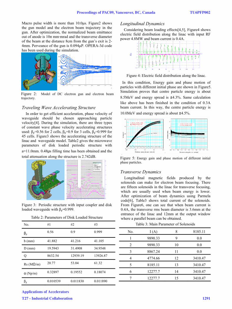
Macro pulse width is more than 10.0μs. Figure2 shows the gun model and the electron beam trajectory in the gun. After optimization, the normalized beam emittance out of anode is 10π mm·mrad and the transverse diameter of the beam at the distance 8cm from the gun’s exit is 2-4mm. Perveance of the gun is 0.094μP. OPERA-3d code has been used during the simulation.
Figure 2: Model of DC electron gun and electron beam trajectory.
Traveling Wave Accelerating Structure In order to get efficient acceleration, phase velocity of
waveguide should be chosen approaching particle velocity[4]. During the simulation, there are three types of constant wave phase velocity accelerating structures used: βp=0.56 for 2 cells, βp=0.9 for 3 cells, βp=0.999 for 45 cells. Figure3 shows the accelerating structure of the linac and waveguide model. Table2 gives the microwave parameters of disk loaded periodic structure with a=11.0mm. 0.48μs filling time has been obtained and the total attenuation along the structure is 2.742dB.
Figure 3: Periodic structure with input coupler and disk loaded waveguide with βp=0.999.
Table 2: Parameters of Disk Loaded Structure
No. #1 #2 #3
βp 0.56 0.9 0.999
b (mm) 41.882 41.216 41.105
D (mm) 19.5943 31.4908 34.9548
Q 8632.54 12939.19 13926.87
Rs (MΩ/m) 20.77 53.04 61.32
α (Np/m) 0.32897 0.19552 0.18074
βg 0.010539 0.011830 0.011890
Longitudinal Dynamics Considering beam loading effects[4,5], Figure4 shows
electric field distribution along the linac with input RF power 4.8MW and beam current is 0.4A.
Figure 4: Electric field distribution along the linac.
In this condition, Energy gain and phase motion of particles with different initial phase are shown in Figure5. Simulation proves that centre particle energy is about 8.5MeV and energy spread is ±4.3%. Same calculation like above has been finished in the condition of 0.3A beam current. In this way, the centre particle energy is 10.0MeV and energy spread is about ±4.5%.
Figure 5: Energy gain and phase motion of different initial phase particles.
Transverse Dynamics Longitudinal magnetic fields produced by the
solenoids can make for electron beam focusing. There are fifteen solenoids in the linac for transverse focusing, which are usually used when beam energy is lower. After optimization of beam dynamics using Parmela code[6], Table3 shows total current of the solenoids. From Figure6, one can see that when beam current is 0.4A, the transverse rms beam diameter is 3.6mm at the entrance of the linac and 12mm at the output window where a parallel beam can be obtained.
Table 3: Main Parameter of Solenoids
No. I (A) 8 8185.11
1 9890.33 9 0.0
2 9890.33 10 0.0
3 8867.24 11 0.0
4 4774.66 12 3410.47
5 8185.11 13 3410.47
6 12277.7 14 3410.47
7 12277.7 15 3410.47
Proceedings of PAC09, Vancouver, BC, Canada TU6PFP002
Applications of Accelerators
T27 - Industrial Collaboration 1291
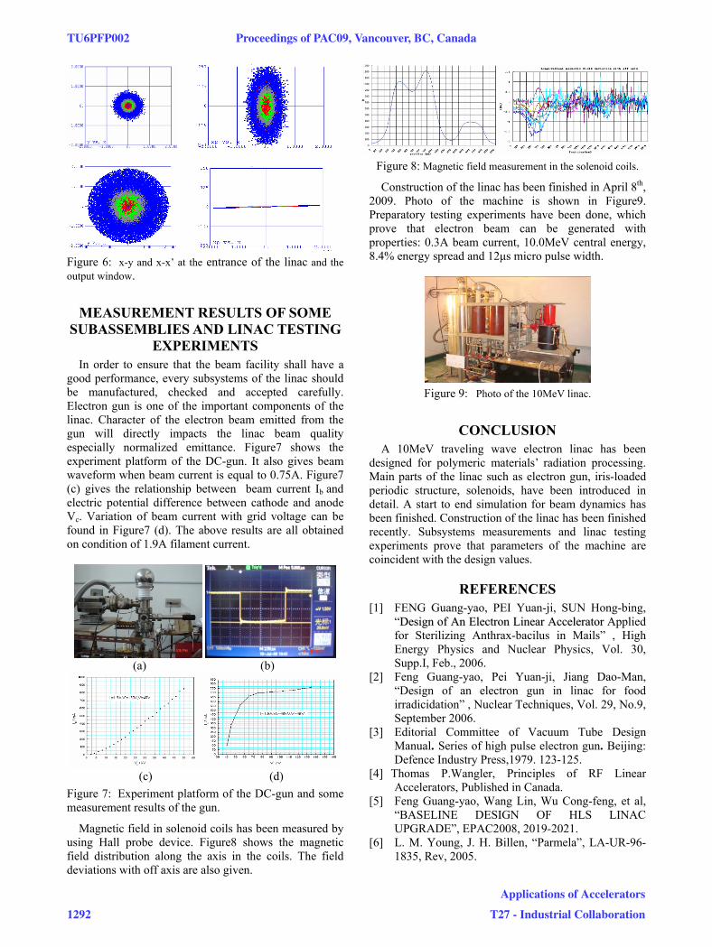
Figure 6: x-y and x-x’ at the entrance of the linac and the output window.
MEASUREMENT RESULTS OF SOME SUBASSEMBLIES AND LINAC TESTING
EXPERIMENTS In order to ensure that the beam facility shall have a
good performance, every subsystems of the linac should be manufactured, checked and accepted carefully. Electron gun is one of the important components of the linac. Character of the electron beam emitted from the gun will directly impacts the linac beam quality especially normalized emittance. Figure7 shows the experiment platform of the DC-gun. It also gives beam waveform when beam current is equal to 0.75A. Figure7 (c) gives the relationship between beam current Ib and electric potential difference between cathode and anode Vc. Variation of beam current with grid voltage can be found in Figure7 (d). The above results are all obtained on condition of 1.9A filament current.
(a) (b)
(c) (d)
Figure 7: Experiment platform of the DC-gun and some measurement results of the gun.
Magnetic field in solenoid coils has been measured by using Hall probe device. Figure8 shows the magnetic field distribution along the axis in the coils. The field deviations with off axis are also given.
Figure 8: Magnetic field measurement in the solenoid coils.
Construction of the linac has been finished in April 8th, 2009. Photo of the machine is shown in Figure9. Preparatory testing experiments have been done, which prove that electron beam can be generated with properties: 0.3A beam current, 10.0MeV central energy, 8.4% energy spread and 12μs micro pulse width.
Figure 9: Photo of the 10MeV linac.
CONCLUSION A 10MeV traveling wave electron linac has been
designed for polymeric materials’ radiation processing. Main parts of the linac such as electron gun, iris-loaded periodic structure, solenoids, have been introduced in detail. A start to end simulation for beam dynamics has been finished. Construction of the linac has been finished recently. Subsystems measurements and linac testing experiments prove that parameters of the machine are coincident with the design values.
REFERENCES [1] FENG Guang-yao, PEI Yuan-ji, SUN Hong-bing,
“DDeessiiggnn ooff AAnn EElleeccttrroonn LLiinneeaarr AAcccceelleerraattoorr Applied for Sterilizing Anthrax-bacilus in Mails” , High Energy Physics and Nuclear Physics, Vol. 30, Supp.I, Feb., 2006.
[2] Feng Guang-yao, Pei Yuan-ji, Jiang Dao-Man, “Design of an electron gun in linac for food irradicidation” , Nuclear Techniques, Vol. 29, No.9, September 2006.
[3] Editorial Committee of Vacuum Tube Design Manual. Series of high pulse electron gun. Beijing: Defence Industry Press,1979. 123-125.
[4] Thomas P.Wangler, Principles of RF Linear Accelerators, Published in Canada.
[5] Feng Guang-yao, Wang Lin, Wu Cong-feng, et al, “BASELINE DESIGN OF HLS LINAC UPGRADE”, EPAC2008, 2019-2021.
[6] L. M. Young, J. H. Billen, “Parmela”, LA-UR-96-1835, Rev, 2005.
TU6PFP002 Proceedings of PAC09, Vancouver, BC, Canada
1292
Applications of Accelerators
T27 - Industrial Collaboration