design, construction and testing of a pololu 3pi...
TRANSCRIPT

1
Design, Construction and Testing of a
Pololu 3pi Robot
Final Report – Group 12
Student 1: Eoin Clancy: 13388656
Student 2: James Clifford: 13340496
Student 3: Cian Costelloe: 13395741
Student 4: Ahmed Wanas: 13503933
Contact e-mail address: [email protected]
Date: 03/04/2014
Engineering Design (EI150)
National University of Ireland, Galway

2
1 Introduction
The following report is an outline of our efforts to complete the robotics challenge. In this project
we had to Programme our Pololu 3pi robot to complete a small course using inbuilt sensors on the
robot. It had to follow a light, follow a line on the ground and then balance itself on a see-saw. The
robot was marked on its ability to complete the course as efficiently as possible. There were many
different types of functions that we could have used within this project by using the Arduino
software to communicate with our robot.
Figure 1: An outline of the Pololu 3pi robot we were provided with and its prototype board, see top left.
The prototyping board was used to solder the different components on to the robot e.g. (the LDRs,
the accelerometer and the resistors). These were all attached to relevant pins in order to
communicate with the arduino.
The Pololu 3pi robot has a number of inbuilt sensors and also works on a number of certain
principles: The robot must be able to drive towards a light bulb by using the motor on each wheel
and by communicating with the analog values being read in by the LDRs, as it goes through a loop
in the arduino software. The robot must also be able to track and follow a line by using the infrared
sensors on the bottom of the robot. This function allows the robot to see the difference between

3
black and white which allows it to follow the line. After this the robot must use an accelerometer
and the motors to balance itself on top of a see-saw.
2 Design Overview
Overall course:
The course commences by turning on the robot. Depending on which button has been pressed the
robot must carry out a specific task. This also came in very useful because if the robot got stuck in a
particular task we could then reset the robot to carry out that task again instead of resetting it from
the start. If button A was pressed the robot went through its light follower loop. If button B was
pressed the robot went through the line follower loop, and if button C was pressed the robot went
through the see-saw balancer loop.
Figure 2: Flowchart of the operation of the code we designed.
2.1 Light follower:
The robot first started the course facing away from the light. Its first task was to rotate 180 degrees
and then it would drive forwards for a set amount of time. Then once it has driven forward the
LDRs would begin to read in values and adjust the motors according to the light intensity. When
the light switches off the LDRs record a big drop in light intensity and then the robot would start its
calibration again to find the next light by rotating right. Once this is complete the code would
begin again and be repeated for the next two lights.

4
2.2 Line follower:
Once the light follower loop had been completed the robot then went into the line follower loop.
This involved rotating once the loop began and searching for the black line using the infrared
sensors inbuilt on the robot. Once the line had been located it was very straightforward for the
robot to follow it without any problems.
2.3 See-saw balance:
Once the line follower loop had been completed the robot then went on to the see-saw balancer.
This involved driving up a see-saw and trying to balance the robot on the pivot point or fulcrum of
the see-saw for a period of 5 seconds. This was achieved using an accelerometer to read in values
of the tilt of the robot. This meant that it could accurately detect a sudden change in tilt and
therefore find the fulcrum of the see-saw by adjusting the motors accordingly.
3 Detailed design
The aim of this project was to complete five separate tasks, three of which were very similar, in the
testing course. From this, we decided to develop three high level functions which would run
sequentially in the main microcontroller loop and would call other lower level and more specific
functions when needed. This allowed us to develop functions of code for specific tasks which we
could test separately but also connect to one another very easily. This method of software design
allowed us to debug very easily.
3.1 Overview of main loop
The main loop was kept as simple as possible. This allowed for ease of input of new sections
of code throughout the program without impacting on other functions. This layout was easy
to understand and often highlighted sections where debugging was necessary.
Figure 3: Main loop which the microprocessor executes to call all necessary functions when required.
As figure 3 shows, we utilised ‘if statements’ as safety features. By pressing the assigned button on
the Pololu 3pi Robot, we could load a specific piece of code whenever it was required. These were
5
very useful in the testing of specific functions of the code once the entire program had been
uploaded.
The main loop also includes just three functions which it calls upon, allowing for easy readability.
Each of these functions represents a single task which had to be completed during the final testing.
3.2 Light tracking
3.2.1. Function Overview
The aim of this section of the code was to bring the robot though sections 1,2 and 3 of the
course. These sections involved finding the light using LDR’s and tracking it up until the robot came
within range of the light sensors. When this occurred, the light the robot was following turned off
and a similar light automatically came on at a 90˚. At this point, the robot had to recalibrate to find
the new light and again it tracked it up until the light switched off. This process was repeated three
times.
We developed a logical series of steps which took the robot through the three stages, and
these will be discussed below.
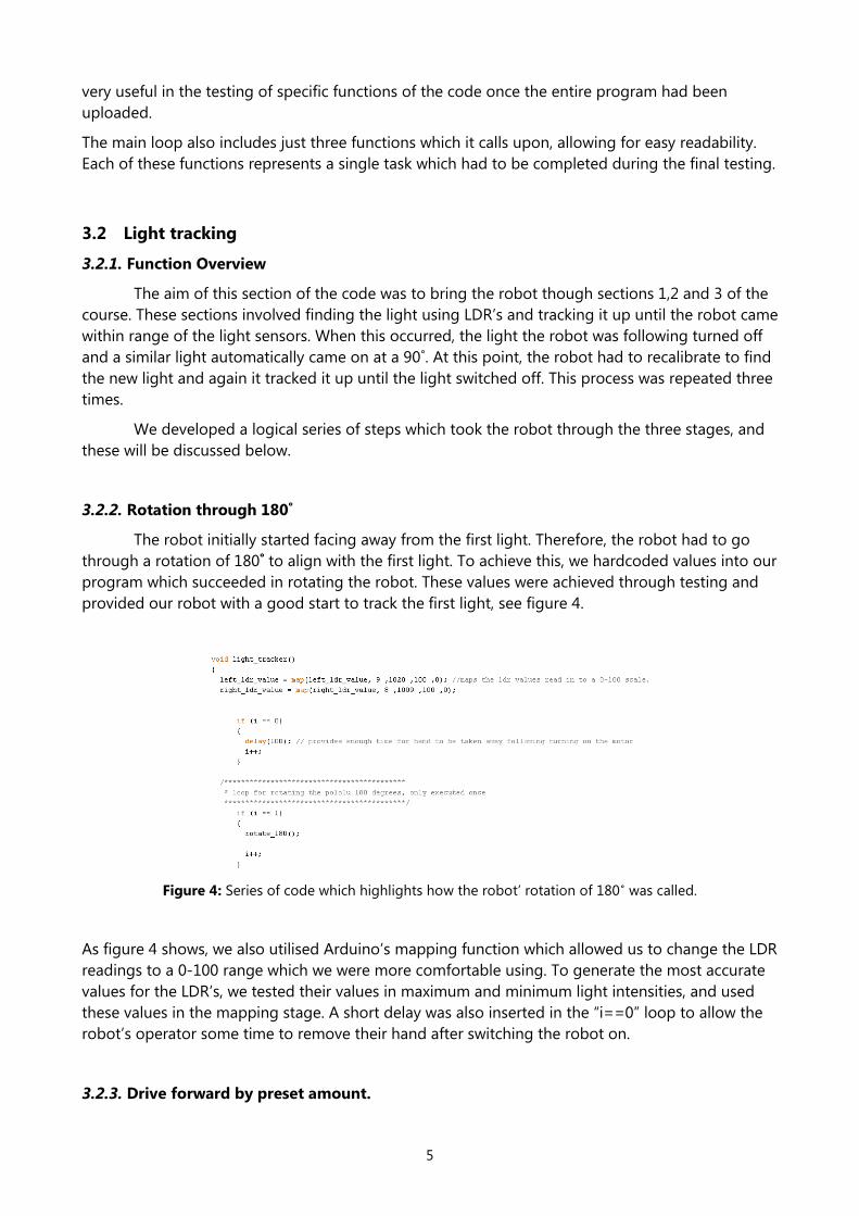
3.2.2. Rotation through 180˚
The robot initially started facing away from the first light. Therefore, the robot had to go
through a rotation of 180˚ to align with the first light. To achieve this, we hardcoded values into our
program which succeeded in rotating the robot. These values were achieved through testing and
provided our robot with a good start to track the first light, see figure 4.
Figure 4: Series of code which highlights how the robot’ rotation of 180˚ was called.
As figure 4 shows, we also utilised Arduino’s mapping function which allowed us to change the LDR
readings to a 0-100 range which we were more comfortable using. To generate the most accurate
values for the LDR’s, we tested their values in maximum and minimum light intensities, and used
these values in the mapping stage. A short delay was also inserted in the “i==0” loop to allow the
robot’s operator some time to remove their hand after switching the robot on.
3.2.3. Drive forward by preset amount.

6
During our testing we were having some minor problems in getting the LDR’s to recognise
the first light bulb. Therefore, we installed a small piece of code which combated this problem. This
function drove the robot straight forward over a short distance, which we had determined in the
testing period, and from the end point of the function, the LDR’s were able to find the light and
track it from there on.
Figure 5: Code for driving the robot straight forwards to come within range of the first light.
This function was only called upon once during the program, following the initial rotation of 180˚.
The motors were also set to stop for a brief period of 0.1 seconds which we found to actually
reduce the jerking motion in going from this piece of code to the actual light follower. The integer
i, was increased by one at the end of the function to ensure that the program moved onto the light
follower function.
3.2.4. Light tracker up to set intensity
This was the most important piece of code in our “light_tracker” function. This was the
function responsible for controlling and adjusting the motors according to the light intensities read
by the LDR’s. We had initially tried a different approach, whereby the robot would move slightly
forwards and to the left if the left LDR value was greater than the right LDR value and the opposite
if the right LDR value was greater, see testing 4.3. However, this led to constant jerking and as a
result it restricted the free-flowing motion of the motors.
As a result, we decided on a sequence of code which was constantly recording the LDR
values and adjusted the motors as was necessary to achieve a straight line when approaching or
following a light. We designed our code using a flowchart, see figure 6, as it allowed for us to
understand each step in the sequence easily and allowed us to work separately on different
functions.

7
Figure 6: A flowchart for the execution of the light following sequence from start to finish.
As before, we used a mapping function to convert the LDR readings into more relatable values, see
figure 7.

8
Figure 7: The code for tracking the light using the LDRs.
The value of light_direction was calculated by determining the current difference between the left
and right LDR values. This integer was then multiplied by a motor constant set to a small integer
value e.g. 4 which just increases the size of the difference and causes the motors to react earlier to
sight differences in LDR readings. This “light_direction” integer was then utilised to set the motor
speeds accordingly, also allowing the motors to reverse which was useful for tight areas, like the
corners of the course. The “motor_speed” mentioned in figure 7, was set to a speed of 50 which
was about 20% of the max speed of the motors. This provided a swift reaction to any change in the
values of the LDR’s.
Through our testing we had discovered that the best way to move the program from following one
light to following the next was to use an pre-determined light intensity value. We tested our Pololu
on the official course and measured the value recorded by the LDR’s when the lights were turned
off by their accompanying sensors. This led to a value of 35 which we called “total_light_int”, see
figure 8. This variable summed the right and left LDR values when the light turned off in the corner
of the course and each time we recorded this value it was less than 35.
Figure 8: The code utilised to recognise when the light the robot was following turned off.
This was an effective method for halting the device once the light had been switched off. The
device came to an steady stop without hitting the wall that the light was attached to. This provided

9
the ideal setup for the next step which was the calibration. The calibration was initiated by setting
the integer ‘jj’ equals to 1.
3.2.4. Light Calibration – Detecting the light
Once the light that the device had been tracking turned off, the device stopped, as
described above. The idea for calibration came about following testing of a previous draft of the
final code, see testing 4.1. In the old method, the device turned 90˚ using a function which made
use of hardcoded values, much like the previously described function, rotate_180˚. However, this
was found to be very unreliable as the Pololu did not always approach the light perfectly.
As a result, we established the calibration method which was much more efficient at finding
the next light in the series. The calibration setup worked by rotating clockwise for two seconds and
then anticlockwise for the following two seconds. This led to the Pololu rotating greater than 360˚.
While rotating, the robot was constantly recording the maximum light intensity values detected by
the LDRs, see figure 9 .
Figure 9: An outline of the calibration code used to find the next light in the sequence.
The maximum light intensity was saved in “sensorMax” and this occurred when the robot was
directly opposite the next light in the course. The value of sensor max was then used in another
function which is called following the termination of the four second while loop in figure 9.
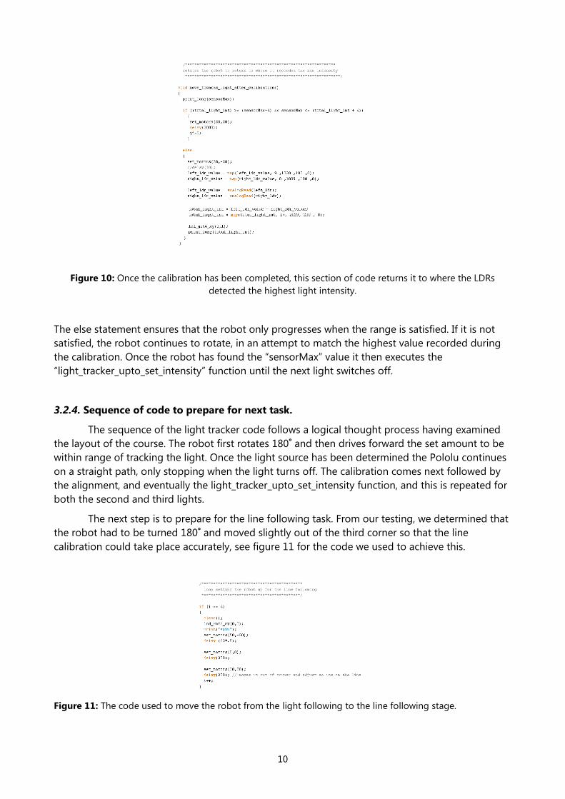
3.2.4. Light Calibration – Facing the light
The next step in the calibration involves returning to where the maximum light intensity was
recorded. The motors spin again, trying to detect a value which is within a certain range of the
recorded sensorMax value. Once a value within this range has been detected, the motors drive for
two seconds in that direction, which is directly towards the light, see figure 10.
10
Figure 10: Once the calibration has been completed, this section of code returns it to where the LDRs
detected the highest light intensity.
The else statement ensures that the robot only progresses when the range is satisfied. If it is not
satisfied, the robot continues to rotate, in an attempt to match the highest value recorded during
the calibration. Once the robot has found the “sensorMax” value it then executes the
“light_tracker_upto_set_intensity” function until the next light switches off.
3.2.4. Sequence of code to prepare for next task.
The sequence of the light tracker code follows a logical thought process having examined
the layout of the course. The robot first rotates 180˚ and then drives forward the set amount to be
within range of tracking the light. Once the light source has been determined the Pololu continues
on a straight path, only stopping when the light turns off. The calibration comes next followed by
the alignment, and eventually the light_tracker_upto_set_intensity function, and this is repeated for
both the second and third lights.
The next step is to prepare for the line following task. From our testing, we determined that
the robot had to be turned 180˚ and moved slightly out of the third corner so that the line
calibration could take place accurately, see figure 11 for the code we used to achieve this.
Figure 11: The code used to move the robot from the light following to the line following stage.

11
From figure 11, it is clear that “set_motors (50,-50)” makes the robot rotate on the spot 180˚. The
motors are then set to pause, just to maintain stability and control. The robot then moves forwards
by a preset distance which we measured through testing and this aligns the robot perfectly on the
line. This section of code also increments the integer i, and this causes it to move onto the line
following function.
3.3 Line Follower
3.3.1. Main loop for calling the functions.
To aid us in designing this section of the code we utilised a main loop which called sub-
functions. The layout of this section of the code was primarily designed using flowcharts and a
logical thought process, see figure 12.
Figure 12: A flowchart outlining how the line following function operates.
The ‘line_follower’ function was responsible for calling all sections of the code which contribute
towards the line following. The two main components of this function can be seen in figure 13.
Figure 13: The function which calls all sub functions required for the line following task.

12
The main components are the line calibration, which aligns the robot perfectly on the black line,
and also the main line follower which continually reads the infrared sensors and maintains a
constant position on the black line.
3.3.2. Calibration for line following.
The calibration for the line following involves using the infrared sensors which are built into
the Pololu 3pi robot. They record within a range of 0 to 4000. The value 2000 represents a perfect
position on the black line with values either side of 2000 indicating that the robot is positioned left
or right of the black line. We utilised a flowchart to outline the progression the robot had to make
during the calibration, see figure 14.
Figure 14: A flowchart outlining the operation of the line calibration
For the calibration, the robot must spin right and then left, recording the infrared values
throughout this process. As mentioned above, 2000 is the perfect reading for positioning on the
line. While the robot is spinning it records its position when it has found a value closest to 2000.
When the spinning motion is complete, the robot returns to this position and provides a perfect
start to the line following code, (See appendix 4 for full code).
3.3.3. Follow the black line.
The main code for tracing the black line was contained in the function, ‘line_follower_main’.
Once the calibration was complete, this marked the commencement of this function. We were

13
unsure as to how to design this function but with the aid of the arduino website and the laboratory
technicians, we developed a process which was very successful, see figure 15.
Figure 15: The code which was used to track the line indefinitely.
The first line of this code passes the variable “sensors” into the function “robot.readLine”. This is
calling the robot to turn on its infrared sensors and read the current value under the robot. This
value is then assigned into the variable position which should be equal to zero if the robot is
positioned correctly on the line. Moreover, the variable “proportional”, should also be zero if this
condition is true.
The next three lines of the code in figure 15, compute the difference in the current infrared reading
to the reading taken immediately before that. Following on from this, the current reading is also
stored for use the next time the code loops, so that the microprocessor remembers its last position.
The code from the declaration of “power_difference” down to the end of the loop is solely
concerned with setting the motors according to the infrared values discussed. The
“power_difference” line of code was copied from the line following example provided with the
Pololu. We found this single line of code to be effective in determining the sharpness of the robot’s
turn along the black line. A positive “power_difference” value led to the robot turning to the right
while a negative value turned the robot to the left.
Through some simple testing along the black line, we could see that the motors were reversing to
turn corners quick, however, this led to the robot losing track of the line a couple of times. As a
result, we decided to prevent the motors from ever reversing by setting the minimum speed to 0.
This was achieved by multiplying the determined “power_difference” value by -1 is it was ever
negative. This led to only positive values being passed in as arguments into the “set_motors”
function. See appendix 4, for extra commenting on this function

14
3.4 Balance on the see-saw.
The see-saw was the most difficult section of the course to complete correctly. During our
testing in the laboratories we developed many different methods in an attempt to balance
the robot, see figure 16 for two methods.
Figure 16: Flowcharts outlining the different approaches used to complete the see-saw task. The left hand
diagram was the old method used. The right hand diagram outlines the method that was used in the final
code.
Our designs often led to the robot balancing the see-saw for two or three seconds, however,
before the five second aim was achieved, the robot started to move again. We finally settled
on the method that brought us the most success, which is described below.
3.4.1 See-saw setup.
The preparation for the see saw task was fairly easy. We encountered a problem in
automatically going from the line following to balancing on the see-saw, therefore we
assigned button C to start the see saw function. Once button C was pressed, see figure 2,
see_saw(); was executed. This code for this function is visible in figure 17.

15
Figure 17: The code used to prepare for the see-saw task.
The ‘for loop’ seen in this figure is required so that the setup only occurs once. During the
execution of this section of the code, the robot is on level surface and has not started to
climb the see-saw yet. It records the current tilt reading provided by the Pololu’s
accelerometer and assigns it to a variable called “tiltmidpoint”. This value represents the
robot on a flat, horizontal surface which are the conditions required for raising the see-saw
at both ends.
The robot then progressed up the ramp at a speed of 30, which was necessary in order to
drive over the initial section of the ramp.
3.4.2 Adjusting on the see-saw to lift both ends.
In this section of the loop the robot has successfully climbed up a portion of the ramp and
is now trying to match the accelerometer value with that which was recorded on level
ground. Figure ... provides the code which we used complete this task.
Figure 18: The code used to creep up the see saw until the midpoint is reached.

16
Whilst on the see-saw, the robot is constantly recording tilt readings. As the current accelerometer
value reaches close to the value stored in “tiltmidpoint”, the robot reduces its speed to ensure
careful and precise movement. If the robot moves past the midpoint of the ramp it is able to
reverse to try and equal the “tiltmidpoint” value. Only when the robot has positioned itself perfectly
in the centre of the ramp will it pause. The necessary values were also printed to the screen to help
us to understand how the robot was progressing throughout this task.
4 Testing
4.1 Turn towards the shining light.
4.1.1 Objectives
To get the robot to turn to face the lights
4.1.2 Methods
Initial method
1. The time taken to turn the robot the required 90°/180° to face the lights was recorded.
2. The motor speed was adjusted to complete the rotation as quick as possible and this
was also noted.
Final method – Use of a calibration
1. The motor was set to spin right for 2 seconds
2. The motor was set to spin left for the next 2 seconds
3. The Pololu constantly read the light intensity values provided by the LDRs.
4. The maximum light intensity value obtained during the rotations was to be stored in
a variable.
5. Once the 4 seconds passed, the robot spun again, searching for a light intensity
which was within a very small range of the maximum recorded.
6. The robot moved off in the direction of the maximum intensity.
4.1.3 Analysis
-
4.1.4 Results
The robot turned towards the light as required
4.1.5 Discussion
-
4.1.6 Conclusion
In conclusion, we successfully got the robot to turn to face the light. This was important because
the robot had to turn when it reached one light to look for the other light.

17
4.2 Print values to LCD
4.2.1 Objectives
Get the LDRs working correctly. Also get the correct values printed on the LCD screen as default
and incorrect readings were constantly being printed
4.2.2 Methods
1. The function “print” was used many times throughout the code as a debugging tool.
2. A rubber band was wrapped around the robot pushing down the pins of the prototyping
board that connected to the Pololu.
3. Code was uploaded to robot
4. Robot was placed on ground and switched on.
4.2.3 Analysis
-
4.2.4 Results
The LCD screen printed out required values. Also the rubber band held the pins together.
4.2.5 Discussion
The LCD now worked perfectly however the rubber band was affecting the robots movement and
performance.
4.2.6 Conclusion
In conclusion, the LCD started to work and started to print out correct values.
4.3 Initial light follower method
4.3.1 Objectives
To get the robot to follow the light efficiently and accurately
4.3.2 Methods
Initial code:
The initial form of the light follower we used consisted of 3 for loops
If the light intensity of the right LDR was greater than the left LDR, then the robot would
turn slightly right and move a small amount forward
If the light intensity of the left LDR was greater than the right LDR, then the robot would
turn slightly left and move a small amount forward
Finally, if the values were within a small range of one another, the robot would drive
straight forwards.
Final method used in final testing
The final method for tracking the light is described in detail in section 3.2.4.
It uses method whereby the light is continually being recorded and the motors are set
according to the difference in light intensity of the left and right LDRs.

18
4.3.3 Analysis
-
4.3.4 Results
Initial method: The robot didn’t follow the phone’s LED most of the time. It was going in a
zigzag pattern and didn’t drive it in a straight line.
Final method: The robot followed the light extremely smoothly and drove in a perfect straight line
when needed. It also was almost instantaneous at reacting to a change in the source of the light.
4.3.5 Discussion
-
4.3.6 Conclusion
We decided to select the final method as it was very efficient and completed the task promptly and
accurately, with minimum to no manually assistance.
4.4 Test line following
4.4.1 Objectives
Test line following without calibration and with calibration.
4.4.2 Methods
Method 1:
1. A black circle was drawn on a white piece of paper
2. The light following code without calibration was uploaded to the Pololu.
3. The robot was placed on the piece of paper and switched on
Method 2:
1. A black circle was drawn on a white piece of paper
2. The light following code with calibration was uploaded to the Pololu.
3. The robot was placed on the piece of paper and switched on
4.4.3 Analysis
-
4.4.4 Results
Using method 1 the robot didn’t follow the black line.
Using method 2 the robot followed the black line perfectly.
4.4.5 Discussion
During this task the robot received input from the five IR sensors on the bottom of the robot,
which it then used to determine its orientation in relation to the line.

19
4.4.6 Conclusion
In conclusion, the Line Follow function didn’t work without calibration. However, we had huge
success with testing the Line Follow function with calibration.
4.5 Balance on see-saw
4.5.1 Objectives
Get the robot to balance on a see-saw.
4.5.2 Methods
Initial method
1. The see-saw code was uploaded to the Pololu 3pi
2. The robot was place by the beginning of the see-saw and switched on
3. The robot drove from bottom of ramp to top
4. Robot took values of accelerometer periodically and stored them in an average buffer.
5. The robot then reversed back to the average of the values
6. This test was repeated two more times.
Final method used in final test
1. The see-saw code was uploaded to the Pololu 3pi
2. The robot was place by the beginning of the see-saw and switched on
3. The robot started on level ground and stored the reading in “midpoint” integer
4. The robot slowly moved up the ramp
5. It kept taking accelerometer values periodically until the reading was within a small range of
the midpoint integer value.
4.5.3 Analysis
-
4.5.4 Results
Initial method: The robot balanced itself on the ramp once and didn’t balance itself the second or
third time.
Final Method: The robot successfully and slowly balanced itself on the ramp twice.
4.5.5 Discussion
Initial method: This test was successful only once and therefore was unreliable.
Final method: This test was more successful than the previous one and more reliable.
4.5.6 Conclusion
We decided to use the final method in our final testing of the Pololu as it was the most efficient at
balancing on the see-saw in the fewer amount of attempts.

20
4.6 Final test
4.6.1 Objectives
The robot had to search for first light drive towards it turn search for second light drive toward it
then turn once again and drive towards the third light. The robot also had to search for a black line
and follow it then try and balance itself on a see-saw for 5 seconds.
4.6.2 Methods
1. The Pololu was placed at the start of the course and was switched on.
2. The first light was switched on and the timing started.
3. Rotation 180° worked.
4. The robot followed the first light.
5. When light went off it stopped.
6. Turned using calibration and found second light.
7. Then crashed in to the wall.
8. Robot could not realign.
9. The code was restarted in the second light corner.
10. Robot still never aligned correctly.
11. The robot was manually moved to the third light.
12. Line follower also manually set up using B button.
13. Our 2 minute time limit finished.
4.6.3 Analysis
-
4.6.4 Results
We received a grade of 7 out of 20.
4.6.5 Discussion
Our robot never recovered after crashing the first time into the wall. The rubber band that was
holding the pins down caused too much friction and prevented the robot from realigning.
When the robot faced the wall between the first and second light, it assumed it had completed the
second light phase.
We also never got to test our robot on the see-saw as we ran out of time.
4.6.6 Conclusion
In conclusion, our Robot wasn’t entirely successful in completing the track due to programming,
technical and timing problems.
5 Conclusions
Before the official test of our robot, we were quite satisfied with our code and felt that it would
complete the tasks without any trouble. We carried out many tests on each task in the lead up to
the official test. Our robot performed very well in these, other than a few flaws (e.g. turning right in
a large arc before travelling to the light). However during the official test, there were a few
21
difficulties. The robot, while travelling to the light, would steer slightly left and rub against the wall
of the track. This happened repeatedly and slowed us down quite a bit. This was something that
never occurred while testing the robot.
Although it did not perform as we expected, it did follow the first light and turned it off
automatically, and carried out the line following task without any trouble. However due to being
slowed down by being stuck against the wall, we did not have time to use our accelerometer in the
see saw task, as a result we were disappointed with our score of 7/20.
6 Recommendations for Future Work
If we were to carry out this project again, there would be a few things we would change. A lot of
time was wasted while testing due to a loose connection in joining the prototype board to the
robot itself, this was causing our LDRs and accelerometer to perform strangely and not provide us
with reliable information. This was a problem which we only solved the day before the official test
by tying them together with an elastic band, and a piece of cloth to protect the prototype board.
A lot more tests could have been carried out in the upcoming weeks to final test. Tests should have
been carried out earlier to get max light intensity values for when the robot turns off the light, and
values from the accelerometer when it was at a maximum positive angle, horizontal and maximum
negative angle. This would have given us more time to hardcode in such values into our code and
make it more reliable.
Numerous tests of our final code should have been carried on the official track, so that we could
tweak it to perform to its best potential on the day. In the end, we feel that it was a lack of testing
which resulted in our low score.
References
1. Anonymous, Arduino, http://www.arduino.cc, accessed 10/03/2014.
Appendix 1 Individual Contributions
A1.1 Eoin Clancy
I was in charge of the design and development of the code for this project. I wrote all of the
functions and designed them myself using flowcharts. In total, I spent about 40 hours coding on
my own and performing small tests to correct any differences which arose due to the inputs from
the LDRs and the accelerometer. I was responsible for commenting the code as well as writing up
the detailed design. I also helped in the writing of the testing section and in the design of the
presentation slideshow. I was also responsible for putting each section of the report together and
editing them to provide a free-flowing report. Outside of the coding, I spent more than 20 hours
on the project.
A1.2 James Clifford
We were all responsible for different parts of this project, Cian and I were responsible for all
the soldering of the extra devices to the prototyping board, I was also responsible for the
conclusion and recommendations part of the technical report. We all contributed towards the
presentation, although the majority of the power point was created by Cian.

22
A1.3 Cian Costelloe
I was responsible along with Jamie for soldering the components onto the
prototyping board e.g. (LDRs, resistors, wires and accelerometer). I did the introduction
and design overview for this report. I also made up the presentation slideshow along with
the help of Eoin.
A1.4 Ahmed Wanas
During the first few week of the robotics challenge project we were split in to two groups a
soldering group and a code writing group. I was also in charge of the robot switching it off and on
and attaching the LCD screen. I was also responsible of supplying batteries for the robot, which
needed 4 AAA batteries. I was also given a number of flowcharts to draw up to explain our code.
Furthermore, I wrote and presented the introduction part of our robotics presentation. Finally, I was
in charge of writing up the testing section and the material cost section of the report.
Appendix 2 Parts, materials and costs
Part Material Source Cost (€)
Pololu 3pi robot - University € 40
20 AAA batteries Alkaline Convenience stores € 25.00
Appendix 3 Reflection
A3.1 Eoin Clancy
If I were to repeat this project again, I would definitely like some help with the coding. I was
responsible for designing the functions and for converting them from pseudo code to C. It would
have been better if the other team members had taken it upon themselves to write some of the
functions for implementation in the final code. I didn’t feel as if the other members were
contributing any alternative ideas to the code I had written.
Overall, I was very disappointed with our final test result because I had put so much time
and effort into the report. We might have achieved a higher grade if we had performed more
testing on the individual pieces of the code. It also would have been less stressful for me if some
members had completed their sections of the report prior to the last day for submission, because I
was left with very little time to put it all together.

23
A3.2 James Clifford
Overall, I was quite disappointed with the performance of the robot. Due to a lack of
testing, our robot did not perform exactly as we would have hoped. We wasted a lot of
time on the light following task and therefore did not get a chance to perform the see saw
task.
If we were to do the project again, the one thing I would suggest is to do much more
testing in the weeks previous to the official test. This is vital and gives us an opportunity to
tweak the code to make the robot more reliable and perform as we would expect.
A3.3 Cian Costelloe
If I was to do this project again I would have spent more time testing the LDRs and I
also would have spent more time learning how to use the Arduino software in order to
code the robot.
A3.4 Ahmed Wanas
I enjoyed the robotics project very much. If I was given a chance to do this project again, I
would use better light sensors and not use an elastic band to hold the pins together. I would also
spend more time testing the robot. I learnt a little about Arduino Programming from this project
and I`m certain I will use what I learnt in my future career. I also think that it was wrong splitting our
group into a soldering group and a coding group because it made it hard for the soldering group
to catch up on the coding process.
Appendix 4 The final code used
#include <OrangutanMotors.h>
#include <OrangutanLCD.h>
#include <OrangutanAnalog.h>
#include <Pololu3pi.h>
#include <PololuQTRSensors.h>
#include <OrangutanBuzzer.h>
/* light tracking variables*/
int left_ldr = 6;
int right_ldr = 7;
const int motor_const = 4; //5
int motor_speed = 50;
int i =0;
int light_direction = 0;

24
int left_ldr_value = analogRead(left_ldr);
int right_ldr_value = analogRead(right_ldr);
int total_light_int;
int buttonA=9;
int buttonB=12;
int buttonC=13;
int loopcounter = 0;
int sensorMin = 200; // minimum sensor value
int sensorMax = 0; // maximum sensor value
int jj = 0;
/* line tracking variables */
Pololu3pi robot;
unsigned int sensors[5];
unsigned int position;
unsigned int last_proportional = 0;
long integral = 0;
#include <avr/pgmspace.h>
/* buzzer variables */
int const buzzer_pin = 10;
OrangutanBuzzer buzzer;
/* accel var */
int tiltmidpoint = 0;
int uu = 0;
void setup()
{
//motors_init();
pinMode(buttonA,INPUT);
pinMode(buttonB,INPUT);
pinMode(buzzer_pin,OUTPUT);
}
void loop ()
{
if (digitalRead(buttonA) == LOW) /************************/
{ // Buttons assigned to each section of
i=0; // the couse, as security feature
} /************************/
if (digitalRead(buttonB) == LOW) /**********************/
{ // i=0 : line_tracker
i=5; // i=5 : line_follower
} // i=7 : see_saw
/**********************/

25
if (digitalRead(buttonC) == LOW)
{
i=7;
}
light_tracker(); /************************/
//calling each func as required
line_follower(); /**************************/
see_saw();
}
/**********************************************************************
* main program for controlling all functions with respect to the light follower
*********************************************************************/
void light_tracker()
{
left_ldr_value = map(left_ldr_value, 9 ,1020 ,100 ,0); //maps the ldr values read in to a 0-100 scale.
right_ldr_value = map(right_ldr_value, 8 ,1009 ,100 ,0);
if (i == 0)
{
delay(100); // provides enough time for hand to be taken away following turning on the
motor
i++;
}
/*******************************************
* loop for rotating the pololu 180 degrees, only executed once
*******************************************/
if (i == 1)
{
rotate_180();
i++;
}
/**********************************************************************
* loop for calibrating and alligning the robot for the next light gate
*********************************************************************/

26
while (i== 2)
{
if (loopcounter < 3) // light code only executes 3 times
{
clear();
if (loopcounter == 0)
{
drive_set_amount(); //the first time it has to follow the light, it rotates and drives forward
a small amount.
}
else //once the ldr value drops below 35, this else statement executes
{ if (jj==1) //this occurs due to light turning off in corner
{ //caused by motion of robot
light_calibrate_setup(); //twists the robot 360 degrees to determine the max light
intensity value recorded
}
if (jj == 2)
{
move_towards_light_after_calibration(); //repositions robot to be in line with max sensor
value recorded
}
if (jj == 3)
{
i=3; //once aligned, the light tracker is actived, which moves the robot towards the
light, adjusting accordingly
}
}
}
else //once the light code has been executed 3 times, it sets i=4, to move onto the line
following code
{
i=4;
}
}
/*******************************************
loop for driving within range of the light
******************************************/
while (i==3)

27
{
clear();
light_tracker_upto_set_intesity();
}
/*******************************************
loop setting the robot up for the line following
******************************************/
if (i == 4)
{
clear();
lcd_goto_xy(0,0);
print("spin");
set_motors(50,-50);
delay (639.5);
set_motors(0,0);
delay(300);
set_motors(30,30);
delay(200); // moves it out of corner and adjust so its on the line
i++;
}
}
/********************************************************
outline of code for calibrating and following the line
*****************************************************/
void line_follower()
{
if (i == 5)
{
calibrateLineSensors();
}
if (i == 6)
{
line_follower_main();
}
}

28
/********************************************************
outline of code for executing the see-saw section of the course
*****************************************************/
void see_saw()
{
// this part of the loop only executes once
for (uu=0 ; uu < 1; uu++)
{
//allows time for the removal of the users hand
delay(2000);
// records the accelerometer value on level ground
tiltmidpoint = analogRead(5);
delay(1000);
// Pololu drives us the see saw for a set time
set_m1_speed(30);
set_m2_speed(30);
delay(2800);
}
int tiltreading;
int motorspeed;
// stores the current accelerometer value
tiltreading = analogRead(5);
// the speed of the motors is set according to the value
// read in from the accelerometer
motorspeed = (tiltreading-tiltmidpoint);
// prints all the necessary values to the screen
clear();
lcd_goto_xy(0,0);
print_long(tiltreading);
lcd_goto_xy(0,1);
print_long(motorspeed);
lcd_goto_xy(5,1);
print_long(tiltmidpoint);
// setting the speed of the motors
set_m1_speed(motorspeed);
set_m2_speed(motorspeed);
delay(50);
}

29
/*******************************************
Rotates the robot 180 degrees, values achieved through testing
******************************************/
void rotate_180()
{
lcd_goto_xy(0,0);
print("rotate");
lcd_goto_xy(0,1);
print("180");
set_motors(50,-50);
delay (639.5);
set_motors(0,0);
delay(300);
}
/**************************************************************************************************
loop setting the robot up for the line following, executed once, following rotation of 180
degrees
**************************************************************************************************/
void drive_set_amount()
{
set_motors(50,50);
lcd_goto_xy(0,0);
print_long(left_ldr_value);
lcd_goto_xy(5,0);
print_long(right_ldr_value);
lcd_goto_xy(0,1);
print("St Frwrd");
delay (300);
set_motors(0,0);
delay (100);
i++;
}

30
/*******************************************
Code for following the light
******************************************/
void light_tracker_upto_set_intesity()
{
int light_direction = 0;
int left_ldr_value = analogRead(left_ldr);
int right_ldr_value = analogRead(right_ldr);
left_ldr_value = map(left_ldr_value, 9 ,1020 ,100 ,0);
right_ldr_value = map(right_ldr_value, 8 ,1009 ,100 ,0);
total_light_int = left_ldr_value + (right_ldr_value);
light_direction = ((left_ldr_value) - (right_ldr_value)) * motor_const;
set_motors(motor_speed - light_direction, motor_speed + light_direction);
lcd_goto_xy(0,0);
print_long(left_ldr_value);
lcd_goto_xy(5,0);
print_long(right_ldr_value);
lcd_goto_xy(0,1);
print("Tracking");
delay(50);
if (total_light_int < 35 ) //value adjusted according to light intensity on course.
{
set_motors(0,0);
clear();
print("<35");
delay(2000 );
lcd_goto_xy(0,0);
print_long(left_ldr_value);
lcd_goto_xy(5,0);
print_long(right_ldr_value);
delay(2000);
clear();
buzzersound(); //beeps to indicate that light tracking task has been completed
loopcounter++; /**********************************/
i=2; // These values are adjusted to prepare the next loop once this loop
jj=1; // has finished
/**********************************/

31
clear();
print_long(loopcounter);
delay(500);
}
}
/*******************************************
callibrates to allign robot on black line
******************************************/
void line_follower_setup()
{
unsigned int counter;
robot.init(2000);
calibrateLineSensors ();
OrangutanMotors::setSpeeds(0, 0);
delay(200);
print("lne setp");
i=6;
}
/*******************************************
code for following line
******************************************/
void line_follower_main()
{
// Get the position of the line.
unsigned int position = robot.readLine(sensors, IR_EMITTERS_ON);
// The "proportional" term should be 0 when we are on the line.
int proportional = (int)position - 2000;
// Compute the change and integral (sum) of the position
int derivative = proportional - last_proportional;
integral += proportional;
// Remember the last position.
last_proportional = proportional;

32
// Compute the difference between the two motor power settings,
// m1 - m2. If this is a positive number the robot will turn
// to the right. If it is a negative number, the robot will
// turn to the left, and the magnitude of the number determines
// the sharpness of the turn. The constant values;
// proportional, integral, and derivative terms can be altered to
// improve performance.
int power_difference = proportional/20 + integral/10000 + derivative*3/2;
// Compute the actual motor settings. Never set either motor
// to a negative value, as it results in unreliability
const int maximum = 60;
if (power_difference > maximum)
power_difference = maximum;
if (power_difference < -maximum)
power_difference = -maximum;
if (power_difference < 0)
set_motors(maximum + power_difference, maximum);
else
set_motors(maximum, maximum - power_difference);
//print current position on line to screen
lcd_goto_xy(0,0);
print_long(position);
}
/*****************************
Code for callibrating robot on the black line
***************************/
void calibrateLineSensors ()
{
int counter=0;
for (counter=0; counter<80; counter++)
{
if (counter < 20 || counter >= 60)
OrangutanMotors::setSpeeds(40, -40);
else
OrangutanMotors::setSpeeds(-40, 40);
// This function records a set of sensor readings and keeps
// track of the minimum and maximum values encountered. The
// IR_EMITTERS_ON argument means that the IR LEDs will be
// turned on during the reading, which is usually what you

33
// want.
robot.calibrateLineSensors(IR_EMITTERS_ON);
// Since our counter runs to 80, the total delay will be
// 80*20 = 1600 ms.
delay(20);
}
}
/*************************************************************************
loop for determining the max light recorded during a 360 degree rotation
*************************************************************************/
void light_calibrate_setup()
{
int long start_time = 0;
int left_ldr_value=0;
int right_ldr_value=0;
int long current_time=0;
int total_light_int=0;
lcd_goto_xy(0,1);
print("Lght Cal");
millis();
start_time = millis();
left_ldr_value = map(left_ldr_value, 9 ,1020 ,100 ,0);
right_ldr_value = map(right_ldr_value, 8 ,1009 ,100 ,0);
// calibrate during the first four seconds
while (start_time > (current_time-4000))
{
current_time = millis();
left_ldr_value = map(left_ldr_value, 9 ,1020 ,100 ,0);
right_ldr_value = map(right_ldr_value, 8 ,1009 ,100 ,0);
left_ldr_value = analogRead(left_ldr);
right_ldr_value = analogRead(right_ldr);
total_light_int = left_ldr_value + right_ldr_value;
total_light_int = map(total_light_int, 17, 2029, 200 , 0);

34
// record the maximum sensor value
if ( total_light_int > sensorMax)
{
sensorMax = total_light_int;
}
// record the minimum sensor value
if (total_light_int < sensorMin)
{
sensorMin = total_light_int;
}
if (current_time < (start_time+2000))
{
set_motors(40,-40);
lcd_goto_xy(0,0);
print_long(total_light_int);
}
if (current_time >= (start_time+2000))
{
set_motors(-40,40);
lcd_goto_xy(0,0);
print_long(total_light_int);
}
}
set_motors(0,0);
lcd_goto_xy(0,0);
print_long(sensorMax);
delay(2000);
jj++;
}
/****************************************************************
rotates the robot to return to where it recorded the max intensity
******************************************************************/
void move_towards_light_after_calibration()
{

35
print_long(sensorMax);
if ((total_light_int) >= (sensorMax-4) && sensorMax <= (total_light_int + 4))
{
set_motors(20,20);
delay(2000);
jj=3;
}
else
{
set_motors(20,-20);
//delay(10);
left_ldr_value = map(left_ldr_value, 9 ,1020 ,100 ,0);
right_ldr_value = map(right_ldr_value, 8 ,1009 ,100 ,0);
left_ldr_value = analogRead(left_ldr);
right_ldr_value = analogRead(right_ldr);
total_light_int = left_ldr_value + right_ldr_value;
total_light_int = map(total_light_int, 17, 2029, 200 , 0);
lcd_goto_xy(0,1);
print_long(total_light_int);
}
}
/************************************************************************************
function for emmiting a buzzer noise, to be played at end of every task completed
************************************************************************************/
void buzzersound()
{
buzzer.playNote(NOTE_A(5), 200, 15);
delay(400);
}