design, construction, and installation of a drainage
TRANSCRIPT

AE554
Design, Construction, and Installation of a Drainage Lysimeter for Use on Sandy, Well-Drained Soils under Turfgrass1
Jovana Radovanovic, Eban Z. Bean, and Alexander J. Reisinger2
1. This document is AE554, one of a series of the Department of Agricultural and Biological Engineering, UF/IFAS Extension. Original publication date February 2021. Visit the EDIS website at https://edis.ifas.ufl.edu for the currently supported version of this publication.
2. Jovana Radovanovic, graduate student, Department of Agricultural and Biological Engineering; Eban Z. Bean, assistant professor, urban hydrology, Department of Agricultural and Biological Engineering; and Alexander J. Reisinger, assistant professor, urban soil and water quality, Department of Soil and Water Sciences; UF/IFAS Extension, Gainesville, FL 32611.
The Institute of Food and Agricultural Sciences (IFAS) is an Equal Opportunity Institution authorized to provide research, educational information and other services only to individuals and institutions that function with non-discrimination with respect to race, creed, color, religion, age, disability, sex, sexual orientation, marital status, national origin, political opinions or affiliations. For more information on obtaining other UF/IFAS Extension publications, contact your county’s UF/IFAS Extension office. U.S. Department of Agriculture, UF/IFAS Extension Service, University of Florida, IFAS, Florida A & M University Cooperative Extension Program, and Boards of County Commissioners Cooperating. Nick T. Place, dean for UF/IFAS Extension.
IntroductionLysimeters are often used to quantify the movement of water, nutrients, or pollutants from the surface or root zone into groundwater below (McLean et al. 2018; Prasad and Hochmuth 2016). Drainage lysimeters are typically used to determine the quantity or quality of leachate that leaves the vadose or root zone. There are multiple ways to design a drainage lysimeter. This publication presents one specific drainage lysimeter design that has been success-fully used in well-drained, sandy soils of central Florida. The design includes a collection chamber that contains portions of the rebuilt soil profile, a leachate reservoir for storing leachate between collections, and a collection tube accessible from the surface for purging the lysimeter with a pump. The leachate reservoir should be purged before it fills completely. When considering the lysimeter dimensions, one should carefully consider the maximum anticipated leachate accumulation depth between purging events to prevent overfilling. Using lysimeters to collect water quality samples can provide a better understanding of nutrient or other solute migration below the surface, which can inform landscape management for environmental protection. This publication presents the materials, construction, instal-lation, and management of a specific drainage lysimeter design (Figure 1) in a step-by-step format.
Schematic of Lysimeter DesignA schematic of this lysimeter design is shown in Figure 1. The generalized design is an upper collection area, wide enough to be representative of the surrounding area, that tapers to a narrower leachate reservoir below. In this case, the diameter was 3 inches. Depending on soil conditions, additional steps may be necessary to avoid preferential
Figure 1. Schematic of lysimeter design showing sizing of different parts.Credits: Eban Z. Bean, UF/IFAS

2Design, Construction, and Installation of a Drainage Lysimeter for Use on Sandy, Well-Drained ...
flow. The length of the leachate reservoir will determine the volumetric capacity of the lysimeter, the depth of leachate collection, and the ultimate depth that will need to be excavated for installation. The capacity of the leachate reservoir can be determined by considering the irrigation and rainfall amounts in the period between purging events (e.g., monthly). A tube running from the bottom of the lysimeter reservoir emerges from the top of the reservoir. This tube should be accessible from the surface for reservoir purging and leachate collection. Use a minimum vacuum pressure to purge the lysimeter without disturbing the soil.
Within the lysimeter collection chamber is the in situ soil profile, which sits upon a layer of pea gravel that was washed with acid and rinsed with deionized water. The pea gravel prevents soil washout and is supported by a rigid fiberglass screen with openings smaller than the pea gravel diameter.
Parts List with Cost
Lysimeter Construction1. Obtain all necessary components and tools from a
hardware store or online.
2. Cut the 3-inch diameter PVC pipe to the desired length (8 inches in this example for turfgrass to accurately capture leachate leaving the root zone; in other cases, whichever length and depth best suit the needs of the specific study). The top of the collection chamber may extend to the soil surface or terminate below the surface. If irrigation or utilities are in place, the top of the col-lection chamber can terminate 12 inches below the soil surface to avoid disturbing any pipes. If the collection chamber is going to sit at the end of the root zone, the
root zone depth of the plant to be studied can be found in different scholarly journals. The top of the collection chamber may also extend to the soil surface to ensure that water that is not taken up by roots or evaporated travels into the leachate reservoir.
3. Cut the 2-inch diameter PVC pipe to a length that will store the maximum anticipated volume between collec-tion intervals. This pipe is the reservoir. In Figure 2, the length of the reservoir is 24 inches, which is designed to store about 11 inches of leachate. The leachate collection depth can be determined by dividing the reservoir volume by the cross-sectional area of the leachate collec-tion section. The leachate collection reservoir should be sufficiently large to store infiltration from total rainfall, run-on (or runoff) from adjacent areas, and irrigation that may leach through the soil profile over the expected period between lysimeter purging events.
4. Drill a small hole through the side of the 2-inch PVC sec-tion, approximately 1–2 inches below the top of the pipe, just below the reducer. This hole is made to feed through a 3/8-inch vinyl tube to the bottom of the reservoir. The tubing should be long enough to extend above the soil surface after installation to allow for purging (e.g., 6 feet). Drill the hole at an angle approximately parallel to the angle of the reducer to prevent sharp bends in the tube (drilling a pilot hole may make this easier to do). The hole’s diameter should be just large enough for the sample collection tube to be inserted through the side wall into the reservoir. Shake out any dust so it does not become trapped within the lysimeter. Seal the drill hole around the collection tube using silicone or epoxy.
5. Cement a 2-inch cap to the bottom of the reservoir section and the reducer onto the top of the reservoir section. Apply PVC primer to both the inside of the cap
Table 1. A list of the tools and parts needed to assemble a drainage lysimeter, along with the estimated price per unit for supplies bought at a hardware store.
Item Required Size and Quantity Price per
Unit ($)
Pea gravel (1/8-inch to 3/8-inch diameter)
1 cubic foot 3.98
Standard fiberglass screen (mesh)
4 inches × 4 inches per lysimeter
6.98
Polyvinyl chloride (PVC) pipe (SCH40)
2-inch outer diameter (OD) (10 feet long)
8.44
PVC cap (SCH40) 2-inch OD 1.78
PVC clear vinyl tube 3/8-inch OD (10 feet long) 2.88
PVC pipe (SCH40) 3-inch OD (5 feet long) 14.80
PVC reducer (SCH40) 2-inch to 3-inch OD 3.88
Total Cost 42.74
Figure 2. Assembled drainage lysimeter with collection chamber, reducer, reservoir, and purge tube shown.Credits: Jovana Radovanovic, UF/IFAS
3Design, Construction, and Installation of a Drainage Lysimeter for Use on Sandy, Well-Drained ...
and the outside end of the pipe and allow it to dry per cement instructions.
6. Apply PVC primer to the 3-inch collection chamber section and the receiving end of the reducer and allow to dry. A thin layer of glue should be applied to the outside of the chamber section that will be in contact with the reducer. Place the fine mesh plastic screen over the opening of the 3-inch end of the reducer. The collection chamber is then inserted into the reducer so that the plastic screen sits snugly between the two. Trim off any excess screen emerging from the reducer.
7. Place the collection chamber inverted on a solid surface. Apply PVC primer to the inside of the reducer and the upper end of the collection chamber and let dry. Apply a thin layer of PVC glue to the outside of the upper end of the reservoir where it will be in contact with the reducer. Insert the reservoir into the reducer.
8. Rinse the lysimeter with a weak acid (e.g., muriatic acid) to remove any chemical or biological contaminants weakly bound to the lysimeter surface. When you have finished cleaning, dispose of the muriatic acid properly. Rinse the lysimeter with deionized water.
9. Wash the pea gravel with deionized water, rinse with muriatic acid, and rinse with deionized water again. Enough pea gravel should be prepared to add 2 inches to each lysimeter.
Installation1. Measure the total length of the lysimeter to estimate the
depth of excavation for the lysimeter installation.
2. If working in an area where there may be any types of utilities (i.e., electricity, natural gas, water, sewer, telecom, or irrigation), locate these before beginning installation.
3. Determine the installation location by choosing a site that is representative of the entire area (typically a location
that does not receive excess water from gutters or runoff from areas upslope of the landscape).
4. If existing vegetation is intended to be preserved after lysimeter installation, consider using a spade shovel to cut through roots. Gently remove the vegetation and root zone, keeping them as intact as possible.
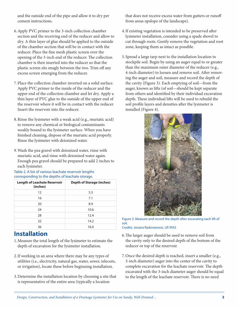
5. Spread a large tarp next to the installation location to stockpile soil. Begin by using an auger equal to or greater than the maximum outer diameter of the reducer (e.g., 4-inch diameter) to loosen and remove soil. After remov-ing the auger and soil, measure and record the depth of the cavity (Figure 3). Each emptying of soil—from the auger, known as lifts (of soil—should be kept separate from others and identified by their individual excavation depth. These individual lifts will be used to rebuild the soil profile layers and densities after the lysimeter is installed (Figure 4).
6. The larger auger should be used to remove soil from the cavity only to the desired depth of the bottom of the reducer or top of the reservoir.
7. Once the desired depth is reached, insert a smaller (e.g., 3-inch diameter) auger into the center of the cavity to complete excavation for the leachate reservoir. The depth excavated with the 3-inch diameter auger should be equal to the length of the leachate reservoir. There is no need
Table 2. A list of various leachate reservoir lengths corresponding to the depths of leachate storage.
Length of Leachate Reservoir (inches)
Depth of Storage (inches)
12 5.3
16 7.1
20 8.9
24 10.6
28 12.4
32 14.2
36 16.0
Figure 3. Measure and record the depth after excavating each lift of soil.Credits: Jovana Radovanovic, UF/IFAS

4Design, Construction, and Installation of a Drainage Lysimeter for Use on Sandy, Well-Drained ...
to keep track of the soil excavated with the smaller auger because this soil will not be used later.
8. Excavate a notch in the sidewall of the large-diameter cavity to create an opening to connect the adjacent void for the collection tube (Figure 5).
9. To aid with lysimeter installation, you can invert the body of another lysimeter (or other equivalent diameter pipe or wooden board) and place it flush with the top of the inserted lysimeter. Then, using a mallet, apply blows to the end cap until the installed lysimeter is at the appropriate depth. A depth of 12 inches below the surface has been used in residential lawns to reach below the root zone as well as any irrigation or utility pipes.
10. Apply about 2 inches of the washed pea gravel into the lysimeter on top of the fine mesh screen (Figure 6). This should limit entry of soil particles into the leachate reservoir. After this step, the soil profile may be rebuilt.
Rebuilding the Soil Profile1. To rebuild the soil profile, measure the depth from the
soil surface to the top of the pea gravel. This depth is used to determine the first soil lift to replace into the lysimeter in order to rebuild the soil profile.
2. Place a proportional (depth available total depth of lift) volume of the excavated soil lift back in the lysimeter and carefully compact the soil to the depth of the bottom of the overlying soil lift (Figure 7). For example, if the depth from the top of the rebuilt soil profile to the soil surface is 18 inches, then the soil should be retrieved from the 16- to 20-inch lift, and packed until the depth is 16 inches to the surface. Then, soil from the next lift should be retrieved (12–16 inches) and packed to a depth of 12 inches to the surface.
Figure 4. Each lift of soil is placed separately on a tarp and labeled to rebuild the soil profile later.Credits: Eban Z. Bean, UF/IFAS
Figure 5. A notch for the collection tube is made and the lysimeter is ready for pea gravel.Credits: Jovana Radovanovic, UF/IFAS
Figure 6. View of lysimeter from soil surface after adding pea gravel onto the mesh screen.Credits: Jovana Radovanovic, UF/IFAS
Figure 7. Pre- and post-lysimeter installation soil profile with rebuilt profile shown within and above the lysimeter. Soil lifts should be replaced according to the depths recorded when these lifts were excavated.Credits: Jovana Radovanovic, UF/IFAS

5Design, Construction, and Installation of a Drainage Lysimeter for Use on Sandy, Well-Drained ...
3. For each subsequent soil lift, the soil is added back to the leachate collection section. There should be excess soil remaining from each lift below the top of the lysimeter to account for the volume occupied by the lysimeter wall thickness and any void space between the lysimeter and soil wall.
4. Be careful not to over compact or under compact the soil by returning all soil lifts to the depth they were excavated. The ultimate goal of rebuilding the soil profile is to return the profile to its pre-excavation structure (including compaction) to the best of your ability.
5. Once the lysimeter is filled with the rebuilt soil profile, excavate a void adjacent to the cavity on the side where the collection tubing is located to store the collection tub-ing (Figure 8). There should be a lateral distance of about 12 inches between the outer perimeters of the irrigation box and the lysimeter once they are both installed. An irrigation control box or a comparable container should be installed to serve as a housing for the sampling tube by maintaining the void and providing access to the tubing from the surface (Figures 9 and 10).
6. Once the void has been created for the tube housing, cut a narrow trench between the housing void and the side of the lysimeter to run the leachate collection tube from the lysimeter into the access box (Figure 8). Install the tube housing with the top flush with the surface to avoid damage from mowing or other landscape maintenance.
7. A narrow trench is cut to connect the void to the adjacent lysimeter cavity for the sample collection tube. After the tube housing is installed and the trench is refilled to bury the collection tube, any excess soil that was excavated from depths below the top of the lysimeter can be used to fill in void space between the lysimeter and the soil wall
(Figure 9). If there is excess soil left after doing this, it can be discarded.
8. Finish rebuilding the soil profile up to the soil surface using the excavated lifts. Any vegetation that was initially removed can be replaced at this point (Figure 10).
Estimating Leachate Loading1. To collect a sample, open the access box, connect the
pump tube to the leachate collection tube, place the pump discharge tube into a leachate collection container, and power on the pump (Figure 11). An adapter may be necessary to make a sealed connection between the pump tube and lysimeter tube in order to create the necessary suction for sample collection. Continue pumping until no leachate is flowing into the collection container. If water quality analyses of the leachate are intended, then the pump and leachate collection container should be decontaminated before collection to preserve data integrity.
Figure 8. Excavate a void adjacent to the lysimeter cavity to store the leachate sampling tube and tube housing.Credits: Jovana Radovanovic, UF/IFAS
Figure 9. The soil profile is rebuilt, the access box is installed, and the collection tube is being rolled to be placed into the access box.Credits: Jovana Radovanovic, UF/IFAS
Figure 10. The turfgrass removed before installation was replaced over the lysimeter. An area was cut out of the sod to access the tube housing.Credits: Jovana Radovanovic, UF/IFAS

6Design, Construction, and Installation of a Drainage Lysimeter for Use on Sandy, Well-Drained ...
2. Measure and record the leachate volume collected. To convert this volume to an effective leachate depth, use the equation below. Divide by the inner cross-sectional area of the lysimeter collection chamber,
where D is the leach depth (in.), V is leachate collection volume (mL), and A is the cross-sectional area of the lysimeter collection chamber (in.2). Transfer leachate to sample containers and follow appropriate preservation and submission protocols for intended analyses.
3. After the sample collection is complete, coil the leachate collection tube into the housing and replace the cover.
4. Once concentrations are known for analyzed leachate samples, they can be used with leachate volumes to estimate leachate loadings since the previous reservoir purge. Use the equation below to convert concentrations and leachate volumes to loadings,
where M is loading rate (lb/1,000 ft.2), n is a constant for unit conversion (3.17 * 10-4), V is leachate collection volume (mL), C is the analyte concentration (mg/L), and
A is the cross-sectional area of the lysimeter collection chamber (in.2).
ReferencesDukes, M. D. 2017. Summary of UF/IFAS Turf and Landscape Irrigation Recommendations. AE436. Gainesville: University of Florida Institute of Food and Agricultural Sciences. https://edis.ifas.ufl.edu/ae436
McLean, D. C., A. K. Koeser, A. L. Shober, Z. Qin, G. Hasing, and R. C. Beeson. 2018. Incorporating Woody Ornamentals into Residential Landscapes to Reduce Nutrient Leaching. ENH1242. Gainesville: University of Florida Institute of Food and Agricultural Sciences. https://edis.ifas.ufl.edu/ep503
Prasad, R., and G. Hochmuth. 2016. How to Calculate a Partial Nitrogen Mass Budget for Potato. SL401. Gainesville: University of Florida Institute of Food and Agricultural Sciences. https://edis.ifas.ufl.edu/ss614Figure 11. Equipment and supplies for leachate sample collection,
including battery-powered peristaltic pump, graduated collection container, rinse bottle with deionized water for decontamination, sample collection bottles, and field sheet for recording leachate volumes.Credits: Jovana Radovanovic, UF/IFAS