design considerations for liquid crystal contact lenses
TRANSCRIPT

The University of Manchester Research
Design considerations for liquid crystal contact lenses
DOI:10.1088/1361-6463/aa9358
Document VersionAccepted author manuscript
Link to publication record in Manchester Research Explorer
Citation for published version (APA):Bailey, J., Kaur, S., Morgan, P. B., Gleeson, H. F., Clamp, J. H., & Jones, J. C. (2017). Design considerations forliquid crystal contact lenses. Journal of Physics D: Applied Physics, 50(48), [485401]. https://doi.org/10.1088/1361-6463/aa9358
Published in:Journal of Physics D: Applied Physics
Citing this paperPlease note that where the full-text provided on Manchester Research Explorer is the Author Accepted Manuscriptor Proof version this may differ from the final Published version. If citing, it is advised that you check and use thepublisher's definitive version.
General rightsCopyright and moral rights for the publications made accessible in the Research Explorer are retained by theauthors and/or other copyright owners and it is a condition of accessing publications that users recognise andabide by the legal requirements associated with these rights.
Takedown policyIf you believe that this document breaches copyright please refer to the University of Manchester’s TakedownProcedures [http://man.ac.uk/04Y6Bo] or contact [email protected] providingrelevant details, so we can investigate your claim.
Download date:25. Mar. 2022

1
DesignConsiderationsforLiquidCrystalContactlenses.
J.Bailey1,S.Kaur1,2,P.B.Morgan3,H.F.Gleeson1,J.H.Clamp4andJ.C.Jones1,*
1. SoftMatterPhysics,SchoolofPhysicsandAstronomy,E.C.StonerBuilding,UniversityofLeeds,Leeds,LS29JT,UK.
2. MerckChemicalsLtd.,UniversityParkway,ChilworthSciencePark,SO167QD,UK.3. EurolensResearch,UniversityofManchester,CarysBannisterBuilding,DoverStreet,Manchester,UK,M139PL
4. UltraVisionCLPL,CommerceWay,LeightonBuzzard,Bedfordshire,LU74RW,UK
Abstract: Switchable liquid crystal contact lenses with electrically controllable focal powers havepreviously been investigated as an alternative to bifocal contact lenses and spectacles for thecorrectionofpresbyopia.Thesimplestlensdesignusesameniscusshapedcavitywithinthelenstocontain the liquid crystal. The design of such a lens is considered in detail, including the nematicalignmentandelectrodesmaterials.TheorganictransparentconductorPEDOT:PSSwasusedasbothelectrodeandplanaralignment.Fourdifferentconfigurationsareconsidered,usingbothplanarandhomeotropicorientationswitheitherhomogenousoraxialalignment.Controllableswitchingofthefocal powerwas demonstrated for eachmode and focal power changes of up to ΔP=3.3 ± 0.2 Dachieved. Such lens designs offer significant potential for a novel form of correction for thiscommonvisualproblem.
Keywords:Liquidcrystals,nematics,electro-opticeffects,switchablecontactlenses
1 Introduction:
Presbyopia is the visual disorder resulting from the reduction of natural accommodation whichhampersfunctionalnearvision[1,2].Itiscausedbytheage-relatedhardeningofthecrystallinelenstissue in the eye and corresponding reduced elasticity of the accommodative mechanism thatchanges lensshape.Presbyopiaaffectsalmostall individuals fromtheirmid-40s.Worldwide itwasestimated that there were 1.272 billion sufferers of presbyopia in 2011 [3]. The population ofpresbyopiasufferersisgrowingstronglyindevelopedcountieswheretheaverageagescontinuestoincrease. Age inevitably leads to presbyopia, but other risk factors include diabetes mellitus,vascularinsufficiency,myastheniagravis,anaemia,influenzaandmeasles.
Giventheobviousimportanceofgoodsightfordailylife,thisfailureofthevisualsystemisatbestamarkedinconvenience.However,evenwhenpresbyopiaiscorrectedwithcurrentlyavailableoptical solutions it has ameasureable impact in the quality of life of an order similar to treatedhypertension[4,5].Tenpercentofpeoplereportthattheywouldtrade5%oftheirremaininglifetoberidofthesymptomsofpresbyopia[5]. Inararehealthcareconditionthiswouldbenoteworthy

AcceptedforJ.Phys.D.:Appl.Phys.(2017) 2
enough, but in a near-ubiquitous condition such as presbyopia, innovative and disruptiveapproachestoitscorrectionpromisewidespreadimprovementtolifequality.Treatingpresbyopiaisthereforeaworthychallengethatcontinuestobecomemorerelevant. Ithasnocureandthebesttreatmentcurrentlyavailableisvisualcorrectionusingspectaclelenses[2].Correctionfordistancevisionmayalsobenecessary (or thewearersmightprefer simultaneously cleardistanceandnearvision),which iswhybifocal or varifocal spectacles areused. Amorediscrete solution, such as acontact lensisdesirableforthosewhodonotwishtowearglasses,forcosmeticorotherreasons.Thesimplesttechniquethatiscurrentlyavailableisusinglensesofdifferingfocalpowersineacheye[2]. Multifocal lenses are also available that focus light from both near and far objects onto theretinasimultaneously[6].Bothtechniquescanbedisorientatingandittakestheusersometimetotraintheirbraintodistinguishbetweenthetwoimagesbeingfocusedsimultaneously.However,notallwearersareabletoadapttoeitherofthesesolutions.Acontactlensthatisautomaticallyabletoselectively switch between the different foci when required is beneficial as it would reduce thisinconvenienceanddisorientation[6–8].
Liquidcrystals(LCs)arealreadybeinginvestigatedasasolutiontomakinglenses[9,10]andcontact lenswith electrically switchable focus [11]. This utilises the inherent birefringenceof theliquid crystal to change the focal power of the lens through electrically controlled changes of theliquidcrystalorientation,andhencerefractiveindex.TherearemanydifferenttechniquesthathavepreviouslybeenproposedforswitchableLC lenses. This includes lensshapedLC layers, [9,10] flatgradientindexlenses[12,13],diffractivelenses[14,15]andflatlensesusinginhomogeneouselectricfields [16–19]. Recently, PMMA lens substrates have been used to fabricate switchable contactlenses[6].Thematerialsandmanufacturingtechniquesusedarecomparabletothosealreadyusedin conventional contact lenses [6–8,20]. A non-uniformly spaced cavity was created within thePMMAlensingsubstrates,withelectrodesandalignmentlayersdepositedontotheirsurfaces.Thecavitybetweenthelenseswasfilledwithanematicliquidcrystaltoformasingleswitchablecontactlens,illustratedinfigure1.Theuseofacurvedsubstratesandvariablecellspacing’sareatypicalforliquid crystal devices. However, forming a one- or two-chambered lens from the contact lensmaterial, suchasPMMA,keepsmanufacturingdifficulty toaminimum.UnlikeLCD,contact lensesarefabricatedsingularly,whichmeansthatadaptationoftheLCfabricationprocessesforusewithcurvedsubstratesisrelativelystraightforward,asdescribedinthispaper.So,itremainsimportanttounderstand themaximumvariation in liquid crystal thickness that is required toprovide sufficientcorrectionforthewearer.
Acontactlensmayneedtoprovidecorrectionforbothdistanceandnearvision.However,the condition of presbyopia represents a weakening of the focussing power of eye and can becorrectedby+0.75D≤ΔP≤+2.5D for thegreatmajorityof sufferers. Ifoneof the indicesof theliquidcrystal(usuallytheordinaryrefractiveindexnoforstandard,calamiticliquidcrystals)matchestheindexofthelens,thenthesubstratesarearrangedsothatthenetcurvatureofthesystemgivesthecorrectlensingpowerforthedistancevision,andthefieldonstatefortheliquidcrystalgivesΔP=+0.75Dto+2.5tohelpthenaturaleyeattainthefocusneededforshortvision.ThechangeinfocalpowerΔPfromathinlensisgivenby;
∆𝑃 = 𝑛! − 𝑛!!!!− !
!!, (1)

J.Bailey,S.Kaur,P.B.Morgan,H.F.Gleeson,J.H.ClampandJ.C.Jones 3
Figure1:Schematicofthebasicliquidcrystalcontactlens.InthisexampletwopositivefocalpowerPMMAlayersformacavitywithanegativefocalpowerbetweenthem.Liquidcrystalwithinthiscavityallowsthefocalpowerofthedevicetobecontrolledbyapplyinganelectricfield.
wheren1=refractive indexofmediumaround lens,n2=refractive indexofthe lens,r1=radiusofcurvatureofthelenseslowersurfaceandr2=radiusofcurvatureofthelensesuppersurface.Alenswillhaveapositivefocalpower(ΔP>0)ifr1>r2whenn2>n1,orifr1<r2whenn2<n1.Likewise,thelenswillhaveanegativefocalpowerifr1<r2whenn2>n1.Foraliquidcrystallens,theelectricallyinducedchangeinrefractiveindexisrelatedtothebirefringenceΔn.Usually,theordinaryindexoftheliquidcrystalismatchedclosetothatofthelenssubstrate(PMMAhasatypicalrefractiveindexof1.495).This means that the liquid crystal has limited additional optical effect in the states where thedirector isnormal tothecavitysurfaces (either field fullyon,oroff). Lensing isdominatedbythedifferenceincurvaturebetweentheouterandinnersurfacesofthecontactlenswhileinthismode.In this fashion, the contact lens can correct for long distance vision, and provide either highlypositiveornegativedioptrecorrection.Switchingtothestatewherethe light traversingthe liquidcrystal cavity in the lens experiences the extraordinary refractive index is only needed to correctnearvision,andtoaugmentthenaturalfocussingabilitythatremainsinthepresbyopiceye.Thisiswhycorrectionofonly+0.75D≤ΔP≤+2.5Disneededfortheliquidcrystalelement.
ThegeometryofthesphericalLCcavity illustratedinfigure2iscalculatedbythefollowingequation[6]:
Δ𝑌 = 𝑅! − 𝑅! − 𝑅!! − 𝑋! + 𝑅!! − 𝑋!, (2)
whereXistheradiusoftheactiveaperture(thehumanpupilistypicallylessthan2.5mm[21]),R1issimilartotheanteriorradiusofthecornea(typically7.8mm[21]),R2=radiusoftheoutercurvatureoftheliquidcrystalcavityandΔYischangeincavityspacingataperturedistanceX.Themaximumspacing in a LC cavity is calculatedbyℎ = ℎ! + Δ𝑌 (shown in figure 2),whereh0 is theminimumspacing to ensuremanufacturability, optical performance and insulation of the electrodes on theupper and lower surfaces of the cavity (typically taken to bebetween2 µm<h0 < 5µm).Using a

AcceptedforJ.Phys.D.:Appl.Phys.(2017) 4
variable spacingwouldpresentproblemswithmanyelectro-opticmediabecause theapplied fieldreducesasthespacebetweentheelectrodes increases.Howeverthis isnotan issuewithnematicliquid crystals, since switching is governed by the Fréedericksz effect and is dependent on theappliedvoltageratherthanfield[22].EnsuringthatthemaximumspacingoftheLCcavityiskeptaslow as possible is important, because this ensures faster switching times, leading to a morecomfortableuserexperience.Asecondreasonforlimitingthecavityspacingisduetothealignmentdegradationthatoccursifthecellspacingisgreaterthan100µm(note,thislimitissomewhathigherthanforatypicaluniformlyspaceddevice,becauseoftheinfluenceofthesurroundingwell-alignedliquidcrystalinthelower-spacedregions).ThismaximumspacingaddsrestrictionsonthegeometryoftheLClayer,whichinturnlimitsthemaximumchangeinfocalpower,asgivenbyequation1.AnLCwithahighbirefringenceshouldbeusedtoensurethattherequiredchangeinfocalpoweroccursforthelowestmaximumcavityspacingh.Furthermore, lowervoltageswouldbeneededtoswitchthelenstoamoderatefocalpowerwhenahigherbirefringenceLCisused.
Figure2:Diagramillustratinghowthefocalpoweriscalculatedusingthelensequation.
Figure3showstherequiredchangeincavityspacingacrossthewidthofthepupil(~4mm)tocause+1.5D,+2.0Dand+2.5Dofopticalcorrection,asafunctionofthedifferenceinrefractiveindexfortheONandOFFstates.Ifthevoltageissufficientlyhigh,typicallythreeorfourtimesgreaterthanthe Fréedericksz threshold voltage (i.e. 3V to 4V), the change in refractive index approaches theinherent birefringence of the liquid crystal,Δn. Figure 3 shows theΔy required for the change infocalpowerfortargetΔP=1.5D,2.0Dand2.5DasafunctionofΔn.UVstablenematicliquidcrystalswith0.24≤Δn≤0.28arepracticable, forwhich the targetΔY is only about20µmto25µm. (The

J.Bailey,S.Kaur,P.B.Morgan,H.F.Gleeson,J.H.ClampandJ.C.Jones 5
figure indicates the room temperature Δn values for the liquid crystals E7 and MLC-2081 forcontext).ForatypicaleyewithreasonablevaluesforΔYandΔn,thedataisapproximatelygivenby:
Δ𝑌 = 3.32 !!!!. (3)
Forhighspacing’s,onlytheOFFtimeτOFFisrelevant.Ignoringflow,thisisgivenby[19]:
𝜏!"" =!!!!
!!!, (4)
where γ1 is the rotational viscosity of the LC director and K is the geometry dependent elasticconstant,takentobetheaverageofsplayK11andbendK33elasticconstantsforthedevicesstudiedinthiswork.Equation4predictsthattheresponsetimeforoptimisedlensesshouldbeabout0.5s,which isdiscussed further in the results section. Furthermore, it is envisaged that faster responsetimesarereadilyachievableusinghigherelasticconstantmixtures(giventhathighΔnLCmaterialstendtohavecorrespondinglyhigherγ1),withonlyaminorcostinoperatingvoltage.
Insummary,nematicliquidcrystalsreadilyofferthemeansforswitching+2.0Datonlyafewvolts,usingasimplelensshapedcavitywithinastandardcontactlens.Inthispaper,wewilldiscussthe different alignment geometries, electrodematerials and fabrication techniques used, to helpoptimisetheswitchablecontactlensperformance.
Figure3:ThemaximumdifferenceincavityspacingchangeΔYthatisrequiredwhentargetingfocusingpowersofΔP=1.5D,2.0Dand3Dasafunctionofthechangeinrefractiveindexbetweenswitchedandun-switchedstates.Thesecurvesarecalculatedusingequation(3).ThebirefringenceofE7andMLS-2081areshowninthisplotforcomparison.

AcceptedforJ.Phys.D.:Appl.Phys.(2017) 6
2 Lensdesignconsiderations:
There are four basic lens design modes, depending on whether the liquid crystal cavity forms apositiveornegativemeniscus lens,andwhetherthequiescent,field-offalignmentconfigurationofthe liquid crystal is vertically aligned (VAN) or planar aligned (PAN), as shown in figure 4. In eachcase,thelensfocalpowerischangedbyelectricallyreorientingtheLCdirectortobeeitherparallelorperpendiculartothesurface,togiveeitherapositiveornegativeopticalchange,ΔP,definedwithrespect to thechange fromthe fieldoff to fieldon statesas shown. This is controlledby surfacealignment and switching of the liquid crystal by applying an electric field across the cavity fromelectrodesdepositedontotheopposinginternalsurfaces.ThedesignchoicedependsuponwhetherapositiveornegativeΔPisrequired;thatis,whetherornotthenearvisioncorrectionisprovidedinfor the fieldOFFor fieldON states. Presbyopia always requires a positive correctionΔP for shortdistance vision. The lensmaybe consideredmore power efficient if designed to provide distancevisionwithoutoperatingvoltage,asthisoperationmodeismorelikelybethelens’smorefrequentsetting.UsinganLCwithapositivedielectricanisotropywouldthenrequireitscavitywithinthelenstohaveanegativefocalpower. Likewise,usingaLCwithanegativedielectricanisotropyrequirestheLClayertohaveapositivefocalpower.ThisoccursforthepositivemeniscuslensinaVANmodewithapositiveΔεliquidcrystal,orforthenegativemeniscuslensinaPANmodewithanegativeΔεliquidcrystal;optionsAandDinfigure4,respectively.
Thepositivemeniscuslenseshavetheminimumcavityspacingattheedgesofthepupil.ThismeansthatswitchingfromtheOFFtoONstateoccursfromtheedgeofthepupilinwards,contrarytothenegativemeniscusoptions.Giventhattheresponsetimeisproportionaltothecavityspacing,h, squared throughequation (4),whichmeans that switchingof the lens is initially fast but slowsmarkedlyatthecentre.Therefore,theopticalcorrectioniseffectivelymuchfasterwhenthepositivemeniscus lens is chosen,because thestrongestoptical changecorresponds to thepartof the lenswith lowest spacing.That is, themajorityof the±2Dcorrectionwhenswitchingoffwouldhappenmuchfasterthanthefullresponsetime.WepredictthatuseofmodeAwouldbemorecomfortablefor theuser for this reasonandatarget fullchange in focus inunder0.5s foranoptimised lens ismorethanadequate(discussedingreaterdetailintheresultssection).
Thevariablespacingleadstoaswitchingsolitonthatmovesfromthefasttoslowregionsasthedirectorrespondstotheappliedvoltage.Thissolitonmayinfluencethedirectoralignmentofthefinal switched state. In practice, conflict with the local surface variations can lead to domainsformingseparatingareasofopposingtilt.Suchdomaincausescattering,whicharedistractingtotheuser and detrimental to the lens performance. For example, consider the negative meniscushomeotropicalignmentofdesignC.Thesolitonbeginsatthepointofthelowestspacingatthelenssymmetry axis. For homeotropic boundaries, switching to the low tilt state is degenerate, andusuallysubjecttorandomsurfacevariations.ForhomeotropiclensesofdesignC,switchingstartsata singlepoint in the cell centre, rather than the circumferenceof startingpoints thatoccurswithlensesofdesignA.Thisislikelytoleadtolessdegeneracyofswitchingsincetheinduceddirectortiltisalsoinfluencedbythefloweffectoftheswitchingsoliton.SuchdomainscanalsobeformedintheplanaralignedcasesofBandD.Thiscanbereducedusingapolyimidewithapretilt>tan(ΔY/Xmax)+2°≈3°toensurethatthealignmenteffectdominates,orbydesigninglenseswithanaxialalignmentsymmetry(i.e.eitheraxialorradialalignment).Thisresultsthattherearefourdifferentalignmentmodeswithuniformdirectorprofilesthatcanbechosen.Animportantpartoftheworkreported

J.Bailey,S.Kaur,P.B.Morgan,H.F.Gleeson,J.H.ClampandJ.C.Jones 7
Figure4: Positive andNegativemeniscus lenses operating in either homeotropic or planar alignedmodes.ThecorrectLCcavityshapemustbeparedwiththeappropriateLCΔɛforthedesiredopticalmodewhenthelensisONorOFF.
here is to distinguish between these alignmentmodes and to determinewhether they have anyimpactonlenselectro-opticalperformance.Thesealignmentmodesare;planarhomogeneous(PH),planar axial (PA), homeotropic homogeneous (HH) and homeotropic axial (HA). Note, thehomeotropicgeometriesdiffersfromconventionalhomeotropicalignmentonly intheuseofsomerubbing (orother suchsymmetrybreaking, includingphoto-alignment) toensure that switchingofthe director is not degenerate but alignedwith respect to the axis of symmetry. In practice, thismightresultfromanegligiblepretiltawayfromthesurfacenormal.Figure5illustrateshowLC’swithapositiveΔɛ(usingalignmentgeometriesPHandPA),willorientatefrombeingparalleltothelenssurface to perpendicular when the potential is greater than the Fréedericksz transition thresholdvoltageVc. Likewise, lensesthatLC’swithanegativeΔɛ (usingalignmentgeometriesHHandHA),willorientatefrombeingperpendiculartoparallelalongthesurfacewhenswitchingaboveVc.Theorientation of the LC when director is parallel to the surface is pre-determined by the rubbingdirectionduringsamplepreparation(discussedindetaillater).

AcceptedforJ.Phys.D.:Appl.Phys.(2017) 8
ThemostcommonelectrodeusedinLClensexperimentstodatehasbeenindiumtinoxide(ITO)[6–8]sputteredontothePMMA.Thismaterialwasselectedpreviouslybecauseofitsrelativelyhigh conductivity and optical transparency, and compatibility with liquid crystal alignment layers.AlthoughitisoftenquotedthatIndiumisbecomingmoreexpensiveduetoitsincreasingdemandindevices [20], a more important issue is that the conductivity and absorption spectra of ITO isdependentuponitsfilmthickness[21,22].Thisisdifficulttocontrolwhensputteringontoacurvedsubstrate,suchasthecontactlensesusedhere. Previously,thePMMAlensesrequiredaspin-on-glasscoatingtoimprovetheadhesionofITOtoitssurface,whichincreasesmanufacturingstepsandcosts. ITO is also a problematic material when deposited onto flexible substrates due to itsbrittleness [23,24]. Thiswas not a substantial problem for PMMAhard contact lenseswhich arerelatively rigid. However, it will become a more important issue when a flexible and morecomfortablesoft-lenssubstrate,suchasahydrogel,isusedoncethelensesbecomecommercialised.Furthermore, an additive manufacturing approach has enormous advantages over sputtering forsimple low-cost fabrication on the laboratory scale. There have already been several studies intoreplacing ITO for use in deviceswith flexible substrates. This includes using conductive polymers[25,26], metallic nanowires [20,27], carbon nanotubes [28,29] and graphene [16,30]. We chosePoly(3,4-ethylenedioxythiophene) polystyrene sulfonate (PEDOT:PSS) as it is a flexible conductingpolymer that can be deposited using simple solution processing techniques (such as spin-coating,screenprintingand inkjetprinting). Thesurface roughnessofPEDOT:PSS is typically<10nmwhendeposited using either spin-coating [34] or inkjet printing [35] techniques. This is an order ofmagnitudelessthantheaberrationsonthesurfaceofthecontactlenswhichhaveamanufacturingtoleranceof<500nm(whichistypicalofcommercialcontactlenses)[6].Therefore,theadditionofPEDOT:PSSdoesnotchangetheopticalqualityofthelenseswhencomparedtothemanufacturingtolerancesofPMMA.PEDOT:PSShasalreadybeenusedinawiderangeofopto-electronicdevicessuchasOLED’s[36],solarcells[32]andliquidcrystalcells[28,29].Ithasalsobeenusedpreviouslyinlargerlensesthatareabletoswitchfocalpower[38–40]andalsousedinsinglepixelcontactlenses.Those single pixel contact lenseswere designed to change optical contrast, instead of their focalpower[41–43].Toourknowledge,thisisthefirsttimePEDOT:PSShasbeenusedasanelectrodetoswitchthefocalpowerofaLCcontactlens.AnotherbenefitofusingPEDOT:PSSisthatit’spolymerlayercanberubbedandusedforLCplanaralignment. Thisreducesthenumberofmanufacturingsteps and eliminates the need for compatible materials and processing techniques for a multi-layeredsystem.

J.Bailey,S.Kaur,P.B.Morgan,H.F.Gleeson,J.H.ClampandJ.C.Jones 9
Figure5: Illustrationofthealignmentmodestestedtodeterminewhethertheychangetheopticalpropertiesof the lenses. Themodesareplanarhomogeneous (PH),planaraxial (PA),homeotropichomogeneous (HH) and homeotropic axial (HA). The red arrows indicate the direction of thealignmentappliedtothelenses.ChangesintheLC’sdirectorareshownwhennoVoltageisapplied(V=0)andabovethecriticalthresholdvoltageVc(V>>Vc)overthecell.

AcceptedforJ.Phys.D.:Appl.Phys.(2017) 10
3 Methods:
3.1Sampleconstruction:
Thesamples inthecurrentworkwereconstructedbymachiningtwohalvesofthecontactlensfromophthalmicgradePMMAblocksusinganOptoform30contactlenslathe(Sterling,Florida,USA).Forthetestlenses,minimalopticalcorrectionforshortsightednesswasincluded,sothatthefirstandsecondsubstrateswerebothuniform,andwithradiiof7.8mmfortheinnereye,andthecurvatureofthecavityfortheouterelement.BothLCcavitiesinthetwoplanarlenses(PHandPA)hadalowerandupperradiusfor7.8mmand8.5mmrespectively. TheradiusofcurvaturetoformtheLCcavitiesforboththehomeotropic lenses(HHandHA)were7.9mmand8.5mmrespectivelyduetoslightlydifferentlensdesigns.
TheconstructionoftheLCcontactlensisillustratedinfigure6(a).BothsidesofthePMMAlenswerecleanedbysonicationfor30minutesin1:4Decon90:deionisedwaterandthenrinsedbysonicationfor30minutesindeionisedwater.Thelensesweredriedusingcompressedairandoutersurfacewasplacedontoaspin-coater. IPAwasdepositedontothelenseswhile itwasspinningat4.0 krpm for approximately 30 seconds. Two different techniques where tested for coating thePMMA lenseswithPEDOT:PSS (Sigma-Aldrich). Both theof the lenses thatusedplanaralignment(PH and PA) used an ‘adhesion layer’ of 40% w.t. Silquest A-287 silane (Momentive) mixed withPEDOT:PSS and spin-coatedonto the internal facing sides of the lens at 3.0 krpm for 30 seconds.Thisadhesionlayerwasbakedat55±5oCfor10minutesandthencooledtoroomtemperature.A‘conductionlayer’of7%w.t.Dimethylsulfoxide(DMSO)(Merck) inPEDOT:PSSwasspin-coatedontopofthe‘adhesionlayer’at1.5krpmfor1minute.Again,theconductionlayerwasdriedbybakingat55±5oCfor15minutesandthencooledtoroomtemperature.Thehomeotropiclenses(HHandHA)werepreparedbypassivatingthePMMAsurfacewith10minutesofUVozoneexposureusingaUVOCST10X10/OES.ThePEDOT:PSSlayerwasspundirectlyontothepassivatedsurfaceat2krpmfor30seconds.Thisinitiallayerwasbakedfor10minsat55±5oCfor10minsandthenallowedtocool back to room temperature. A second PEDOT:PSS layer was added by spin-coating onto thepreviouslayerat2krpmfor30seconds.Thesecondlayerwasbakedfor15minsat55±5oC.Alloftheseprocesseswererepeatedfortheopposinglenssubstratesoacompletecontactlenscouldbeconstructed.
Theorientationofthedirectorwasappliedtotheboththeplanaralignedlenses(PHandPA)byrubbingdirectly intothePEDOT:PSS layer. Bothof thePEDOT:PSS layersneedtoberubbedtoformanti-parallelalignmentforthePHandPAalignmentmodes.CaremustbetakenwhenaligningthePH layers as their lineardirection caneasilybemisalignedduringassembly. This ismitigatedwhenusingPAorHAalignment, as the circular symmetry thenmeans that the sample cannotbemisalignedwhen rotating the sample. ThePAalignmentwaspreparedbyplacing the lensontoaspin-coaterandapplyingrubbingclothtothePEDOT:PSSlayerasthesamplerotates.Homeotropicalignment for the HH and HA alignment layers was applied by spin-coating SE-1211 polyimide(NissanChemical)ontothePEDOT:PSSelectrodelayer.Thispolyimidelayerwasthenhardenedbybakingfor3hoursat50oC. TheHHalignmentwasappliedbyrubbingthepolyimidelayer linearly.HAalignmentwasappliedusingthesamespin-coatermountedtechniqueasPA.BoththeHHandHAalignmentmodesonlyrequiredonesideofthelenscavitytoberubbed.Thiswasshowntobe

J.Bailey,S.Kaur,P.B.Morgan,H.F.Gleeson,J.H.ClampandJ.C.Jones 11
sufficient to predetermine the alignment direction when switching. Also, it is not possible tomisalignthehomeotropicsampleswhenusingthistechnique,asonlyonesiderequiresrubbingforbothHHandHA.RubbingwaspreferentiallyappliedtotheconvexsurfaceforboththeHHandHAlensesprepared,asitwaseasiertopreparethanusingtheconcaveside.
Figure6: (a) Illustrationof theparts used to construct the liquid crystal contact lenses. The innersurfaces of the PMMA lens substrates are coated with the electrode/alignment layer PEDOT:PSS.Short circuitingwas prevented by using a 2.3μm spacer film. Electrical contact between externalwiresandcellwas improvedbyusingsilverpaint. Eachcellwas filledwith the requiredLCbeforesealing it with UV glue. (b) Completed liquid crystal lens with wires attached leading to a signalgenerator.
Conductivity between the PEDOT:PSS electrode layers and the connecting wires wasimprovedbyapplyingsilverpainttotheedgesofthelens.A2.3μmmylarspacerfilm(therefore,h0= 2.3μm from figure 2) was inserted between the two halves of the contact lens to prevent thedevice from short circuiting. The planar and axial lenses were assembled by filling the concavesurfaceoftheupperlenswiththeappropriateLC.
The LC chosen for our lens with planar and axial alignment was E7 due to its largebirefringence(Δn=0.24)andhighdegreeofcharacterisationintheliterature.Alargerbirefringenceincreases the switchable focal power range, as discussed previously. The largest change in focalpower was predicted as 2.53D, using equation 1. The negative dielectric LC chosen for thehomeotropiccellwasMLC-2081(Δn=0.210),whichwasusedbySyedet.al.intheirsimilarcontactlenswithITOelectrodes[8].Thelargestchangeinfocalpowerfortheselenseswaspredictedtobe1.88D. The twohalvesof the lenseswereassembledafter filling thecavitywithLC. UVgluewas
AcceptedforJ.Phys.D.:Appl.Phys.(2017) 12
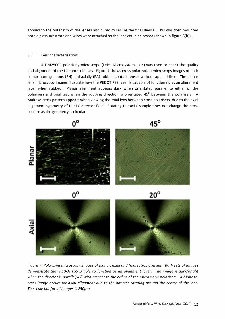
appliedtotheouterrimofthelensesandcuredtosecurethefinaldevice.Thiswasthenmountedontoaglasssubstrateandwireswereattachedsothelenscouldbetested(showninfigure6(b)).
3.2 Lenscharacterisation:
ADM2500Ppolarizingmicroscope (LeicaMicrosystems,UK)wasused tocheck thequalityandalignmentoftheLCcontactlenses.Figure7showscrosspolarizationmicroscopyimagesofbothplanarhomogeneous(PH)andaxially(PA)rubbedcontact lenseswithoutappliedfield. TheplanarlensmicroscopyimagesillustratehowthePEDOT:PSSlayeriscapableoffunctioningasanalignmentlayer when rubbed. Planar alignment appears dark when orientated parallel to either of thepolarisers and brightest when the rubbing direction is orientated 45o between the polarisers. AMaltese-crosspatternappearswhenviewingtheaxiallensbetweencrosspolarisers,duetotheaxialalignmentsymmetryof theLCdirector field. Rotating theaxial sampledoesnotchange thecrosspatternasthegeometryiscircular.
Figure7:Polarizingmicroscopyimagesofplanar,axialandhomeotropiclenses.Bothsetsofimagesdemonstrate that PEDOT:PSS is able to function as an alignment layer. The image is dark/brightwhenthedirectorisparallel/45owithrespecttotheeitherofthemicroscopepolarisers.AMaltese-cross image occurs for axial alignment due to the director rotating around the centre of the lens.Thescalebarforallimagesis250µm.

J.Bailey,S.Kaur,P.B.Morgan,H.F.Gleeson,J.H.ClampandJ.C.Jones 13
The focalpowerandoptical qualityof the contact lensesweremeasuredusingapurposebuiltopticalset-up,usinganexpanded10mW589nmlaserasthelightsource(illustratedinfigure8(a)).PlanaralignedlensexperimentshadpreviouslyusedalinearpolarisertopreferentiallyselectthefocalpointfromthenerefractiveindexcomponentoftheLC[6–8,20].Preferentialselectionofthene focalpoint ismorechallengingwithaxialalignmentduetothedirectorrotatingaroundthecentreofthelens.AslitwasusedtoremovethemajorityoftheLCinthelensthatwasnotalignedparallelwith the linear polariser. The remaining, predominantly parallel, LC in the axial lenswasilluminatedbythelinearlypolarisedbeampath(illustratedinfigure8(b)).Aplano-convexlenswasusedtofocusthebeamontoaBC106-VISCCDbeamprofiler(Thorlabs,NewJersey,USA)whichhadapixelsizeof6.47μmandacaptureareaof1360x1024(8.8mmx6.625mm).Theplanarlensesused a 4D plano-convex lens, whereas the homeotropic lens required a 10D plano-convex lenes.ThiswastoaccommodateforthesmallchangesinthePMMAsubstratesandthedifferingLCsusedintheplanarandhomeotropicdevices.
Figure8:Illustrationoftheopticalset-upusedtomeasurethefocalpowerandqualityoftheliquidcrystalcontact lenses isshowninpanel(a). Thedetectorneededtobemovedtowards/awayfromthe lenstomeasurethefocalpointwhen increasingtheappliedpotentialovera liquidcrystalwithpositive/negativeanisotropyrespectively.Aslit(width=460±30μm)wasusedtomeasureasectionof the axial aligned lens that is comparable to a planar lens geometry,which is illustrated by thediagramshowninpanel(b).
Asinusoidalsignalwithafrequencyof23kHzwasappliedtotheelectrodesonthelensusingan Agilent 33500B series signal generator. The potential was incrementally increased while theopticalresponseonthebeamprofilerwasanalysed.Alllensesshowedachangeinfocalpowerafterswitching above the Fréedericksz transition. The change in focal power was calculated byrepositioningthedetectortothefocuswherethebeamprofile’smaximumintensityoccurred.This

AcceptedforJ.Phys.D.:Appl.Phys.(2017) 14
measurementwasusedwiththefollowingequationtocalculatethefocalpowerofthecontactlens[44]:
𝑃 = 𝑑 !!! − !! ! !!!! !!! !!!
!!, (5)
where𝑑 !!! = distance between contact lens and plano-convex lens,𝑑 !!! = distance betweenplano-convexlensanddetectorand𝑓!=focalpointofplano-convexlens.Atimedelaywasincludedwhen the applied voltage was increased and when the measurements were made. This was toensure that the liquid crystal layer had re-orientated to an equilibrium state during themeasurements. Thewaitingduration for theplanar andaxial lensmeasurementswas2minutes,whereasalongerperiodof5minuteswaschosenfortheslowerhomeotropiclenses.
TheONandOFFswitchingtimesforthelensesweremeasuredusingaphotodiodemountedonto the polarising microscope. Changes in optical intensity were measured through an x5magnificationobjectivelens,whichhadafieldofviewdiameterof2.2±0.1mm.Switchingtimeswithrespect to different voltages were measured in order to assess the performance of the lens atdifferentpowermodes.
4 Results
Alllensesshowedchangesinrefractiveindexwhenviewedundercrosspolarisersandwhensufficientpotentialwasapplied,showninfigure9.Theplanarlensshowedlargeuniformcolouredareas when viewed at 45o with respect to polariser and analyser angle and switched past theFréedericksztransitionfigure9(a)).Thisisduetotherefractiveindexofthecavitychangingastheas theLCre-orientates frombeingparallel toperpendicularwithrespect to thesurface. Theaxiallensalsoshowschanges in refractive index,with theMaltesecrosspatternbeing retained tohighswitching voltages (figure 9(b)). Reverse tilt domainswereobserved in both the simple and axialplanarlenses,butcausedmoredeleteriousscatteringinthesimpleplanardevices.However,thesedomains no not occur when using homeotropic alignment (figures 9(c) and 9(d)), but theirhomogeneousandaxialalignmentisapparentwhentheyarebeingused.
The focal power of the PH and PA contact lenses had both increased when the appliedpotentialwas raised, shown in figure 10(a). Alternatively, themagnitude of the focal power haddecreasedfortheHHandHAlenseswhenincreasingtheappliedpotential(fig10(b)).Thiswasdueto all lenses having a negativemeniscus LC cavity, which corresponds to the situations discussedpreviouslyfigure4(c)and4(d).Therefore,thepre-setforreadingmodeisONwhenusingPHorPAalignmentandOFFwhenusingHHandHAalignment.Inpractice,changingthelensshapeoftheLClayerfromconcavetoconvex(designsAandB)maybepreferablefortheparticulartask,butisyettobestudied.
ThePHandPAlenseshadthelargestmeasuredchangesinfocalpower,tendingtosaturateabove about 4V.At 6VRMS, the focal powerswereΔP ≈2.48 ± 0.13D andΔP ≈3.27 ± 0.20D forsimpleplanarandaxialplanar,respectively.ItwaspreviouslycalculatedthatthemaximumchangeinfocalpowerpossiblewithE7usingthespecified lenseswas2.53D. However,evenasmall2.5%changeintheradiusofcurvatureinoneofthelensesthatformstheLCcavityisenoughtoincrease

J.Bailey,S.Kaur,P.B.Morgan,H.F.Gleeson,J.H.ClampandJ.C.Jones 15
Figure9:Crosspolarisermicroscopyimagesoflensesthatas‘switched’byapplying4.24VRMStothecontactlenses.DomainswereobservedinonlytheLClensesfilledwithE7(Δɛ>0),shownincaptionsa)andb).Maltesecrosspatternsoccurfromthecirculargeometryofaxialalignment,shownincaptionsb)andd).Thescalebarsmicrographsareall250µm.Directionsofthepolariser,analyseranddirectorarenotedbyP,Aandnrespectively.
thechangeinfocalpowerto>3.3D.This is illustratedinfigure11,wherechangeinfocalpoweriscalculatedwith respect to changes in the LC cavities outer radius r2 (the inner radius r1was keptconstantat7.8mm)usingequation1.Alargerouterradiusincreasesthechangeinfocalpower,aswellasthe largestspacing inthe lensΔY. Thesesmall increases inradiicanbecausedduring lensassembly,asthesubstratesareflexibleenoughtobendwhentoomuchpressureisapplied.
TheHHandHAlensesbothbegantosaturateat>6Vwiththeirmaximumchangesinfocalpowers being ΔPHH = 1.52±0.25D and ΔPHA = 1.92±0.26D respectively. Thesemeasurementswereaboveandbelowexpectedchangeinfocalpowerwerecalculatedtobe1.88D. It is likelythatthe

AcceptedforJ.Phys.D.:Appl.Phys.(2017) 16
variationsareduetodiscretechangesinthelensshapeduringthefabricationprocess,asdiscussedearlier.
Figure10: Panel (a) shows that the focalpower increased forbothPH (blue squares)andPA (redcircles) alignment modes were increasing with respect to voltage once past the Fréedericksztransition. Panel (b) shows the focal power of the homeotropic lens degreasing as the voltage isincreased forbothHH (blue squares)andHA (redcircles)alignmentmodeswhengreater than theFréedericksz transition. The error bars for all data points were calculated by the propagation ofuncertaintyforthepositionoftheopticalcomponentsduringmeasurements.

J.Bailey,S.Kaur,P.B.Morgan,H.F.Gleeson,J.H.ClampandJ.C.Jones 17
Figure11:ThegreatestchangeinfocalpowerwithrespecttothecurvatureoftheLCcavitywascalculatedusingequation1.TheinnercurvatureoftheLCcavityr1,waskeptconstant,whiletheoutercurvaturer2wasvaried.Greaterchangesinfocalpowerareachievedwhenincreasingthedifferenceincurvaturebetweenr1andr2.ThisismorepronouncedwhenusingLC’sofgreaterΔn.
The2Dintensityoutputofthebeamprofilerwasalsousedtoassessscatteringlossesinthelens,asshowninfigure12.Comparisonbetweenthelensesiscomplicatedduetotheuseoftheslitto sample the central area only of the lenses only. Unfortunately, this technique becomes lessefficientwhenapproachingthecentreofthelensfortheaxialalignment.Therefore,someoftheseunwantedpolarisationswillbepresentwhenmeasuringthesampleandcouldbemisinterpretedasscattering.Microscopicevaluationof the lensesshowsthat thedegreeofscatteringwas lowest inthehomeotropicHHandHAlenses.
Responsetimesforallfourmodesareshowninfigure13.Caption(a)showsacomparisonfor the response timewhen switchingONall 4 lenses. ThePA,HHandHAall switchedbelow1swithinthe2.2±0.1mmdiameterregiontested.Furthermore,increasingthevoltagealsomakesthelensesmoreresponsive,withthesethree lensesapproaching<0.5sat>6Vrms. ThePHalignment isconsiderably slower than the other three alignment modes when switching the lens on. Largedomainswereobservedwhenswitchingthislens,takingafewsecondsforthehomogenoustextureto be achieved. This optical instability effectively increases the switching time of the device andcauses distractive scattering to occur during the switching process. However, changing thealignmentmodefromPHtoPAdramaticallychangedtheresponsetime,makingitcomparabletoHHandHAlenses.TheresponsetimeswhenswitchingthelensesOFFwithrespecttovoltageare

AcceptedforJ.Phys.D.:Appl.Phys.(2017) 18
Figure12:2DprojectionofbeamintensitymeasuredusingaBC106-VISCCDbeamprofiler.Alloftheintensitiesarenormalisedsothemaximumandminimumarealwaysscalledtobe0%and100%respectively.Theaxialalignmentappearedtoshowmorescatteringthanthehomogeneousalignmentforboththeplanarandhomeotropiclenses.However,thisismostlikelyduetothemeasuringtechniquewhereaslitwasusedinsteadofaradialpolariser.Allscalebarsinthisfigurecorrespondto250μm.

J.Bailey,S.Kaur,P.B.Morgan,H.F.Gleeson,J.H.ClampandJ.C.Jones 19
shown in caption (b). The HH, PH and PA alignmentmodes all had comparable response times.Comparatively, theHAalignmentmodehasamuchslowerOFF response time. This isnotduetoerrorof the lens spacing, since theONtimewascomparable to theHH lens.TherewasnegligiblescatteringinthisgeometryandthecauseoftheslowOffHAremainsunclear.
5 Discussion
ThePMMAsubstratesused intheseexperimentswereusedduetotheirhistoricalcontextandbeingmorerigidandeasiertousethanamodernhydrogelmaterial.However,considerationshavealreadybeenmadeforwhenthePMMAsubstratemightbereplacewithamorecomfortableandflexiblematerial (suchasahydrogel). PEDOT:PSSwasshowntobefunctionalasanelectrodelayer for all four of the alignmentmodes tested. Another benefit of PEDOT:PSS was its ease ofdeposition, as it did not require high vacuum sputtering techniques like ITO. Inkjet printingPEDOT:PSS is also possible, which increases deposition control and reduceswaste. Furthermore,polymerelectronics,antennaandpowersupplycanalsobedepositedusing ink-jetprinting,whichcouldsimplifymanufacturingfurther.
Four different alignment techniques were tested whilst using PEDOT:PSS as an electrodelayer.BoththeHPandHAalignmentswerepreparedbyrubbingdirectlyintothePEDOT:PSS,whichwasshowntohaveexcellentalignmentproperties.HPalignmentwasinvestigatedasacomparisontopreviousLClensexperiments[6,8].Axialalignmentwasinvestigatedinordertotryandsimplifythe manufacturing process. However, this lens was more difficult to measure due to its morecomplexgeometry.Itmightbepossibletoovercomethischallengebyusingeitheraradialpolariser,or a second LC layer to make the lens polarisation independent. Homeotropic alignments weresuccessfully achieved by depositing SE-1211 polyimide onto of the PEDOT:PSS layer. HH and HAalignmentswereachievedbyrubbingthelensesinaplanarandaxialdirection,respectively.
Allof the lenses showedacontrollablechange in focalpowerwhenapplyinganadequatepotentialoverthelens.ThisdemonstratedthatallalignmenttypescanpotentiallybeusedinfutureLClensapplications.ThePA,HHandHAalignmentmodeswereeasiertoassemblethanthePHlens.Domainshadoccurred inbothof thehomogeneous lenses (PHandPA),butnot thehomeotropiclenses(HHandHA),asshowninfigure9.However,usingaxialalignmentdidreducethesizeofthedomaininthePAlens,whencomparedtothePHlens. This isduetothepre-tiltofthealignmentlayerhavingthesameaxialsymmetryasthecurvatureofthelens,ratherthanbeingwiththechangeinanglebetweenthesubstratesforonehalfofthelensandagainstitfortheother.Therefore,thedifference in thepre-tilt anglebetween theanti-parallel alignment layerson theupperand lowersurfaces isconstant. This isnot thecase forPHalignment,as thedifferencebetweentherelativepre-tiltangles for theupperand lowersurfacesshiftsas thedirectorpassesover thecurvatureofthe lens. These changes result in differences of splay throughout the lens curvature, which canresultinreversetiltdomainsformingduringtheswitchingevent.Theopticalqualityoftheselenseswilldiminishasthesedomainswillcausescattering.DomainsarenotformedwhenusingHHorHAalignmentmodes.

AcceptedforJ.Phys.D.:Appl.Phys.(2017) 20
Figure13:LensresponsetimesforwhenthelensesarebeenswitchedONandOFFareshownincaptions(a)and(b)respectively.ThePH,PA,HH,HAalignmentmodesweretestedandshowninbothplotsasredcircles,bluesquares,greendiamondsandblockcrossesrespectively.Thesemeasurementsweretakenusingaphoto-diode,althoughthesubjectiveexperienceofsuchnegativelensesislikelytobemuchfasterthanthetimesshownhereinpractice.

J.Bailey,S.Kaur,P.B.Morgan,H.F.Gleeson,J.H.ClampandJ.C.Jones 21
Theoverall reductionof thechange in focalpowerbetween thehomogeneous lenses (HHandHA),whencomparedtotheplanarlenses(PHandPA),isduetoacombinationoftheMLC-2081havinga lowerbirefringencethanE7andthedifference incurvature(r2–r1)oftheLCcavitybeingreduced.ThiscanbecompensatedusinganLCwithahigherΔnand/orincreasingthedifferenceincurvature between r1 and r2 (whichwould also increaseΔY and the switching times, as discussedpreviously). Therewasagreater change in focalpower for theHA lens than theHH lens. This iscomparabletowhenthechangeinfocalpowerforPHwasgreaterthanPA.Thiscouldindicatethataxialalignmentresultsingreaterchangeinfocalpowerthanhomogeneousalignment.However,alargersamplesetwouldbeneededtodeterminewhetherthis isanadequateconclusion,asotherfactors(suchassmallchangesinlensshape)couldbeaddingvariationtotheseresults.
Response times of the LC lenses are difficult to quantify aswe do not knowwhether ourmeasurementswillcorrespondtoperceivedswitchtimesbyatestsubject.Awearerwouldbemoresensitivetochangesatthecentreofthelens.ThelensestestedhaveanegativemeniscuswiththelowestspacingatthecentreofthevisionsothattheLCswitchesfromthecentralregionoutward.Therefore, the perceived switching times ismuch faster than the opticalmeasurements reportedhere. For this reason, a negative meniscus lens is preferable when using this type of switchablecontactlens.
Figure14showsthelensingcapabilityoftheHHlenswhenON(4.95V)andOFF(0V).A1951USAFresolutionchartisinfocuswhenthelensisswitchedOFF(nearvisionmode)andoutoffocuswhen switchedON (distance visionmode). Region 0 from theUSAF resolution chart is shown infigure14,wherethebarsandnumberscanbedistinguished.Switchingonthelensresultedintheimagescomingoutoffocus,makingthemmoredifficulttodistinguish.Itwasnotpossibletotakesimilar images using the axial alternatives, as the two focal points fromboth ne and no refractiveindices images occurred when the lenses were switched ON. Using the slit would significantlydiminishthefieldofviewandaradialpolariserwasunavailable.Fieldofviewiscurrentlydifficulttodetermineasitisusuallymeasuredsubjectivelybyauser.Thecontactlensesinthispaperhavenotyetbeenplacedona testsubject’seye. However, thegeometry is similar to thatofconventionalcontactlensesandsoasimilarfieldofviewisexpectedinpractice.
For a nematic liquid crystal, both the refractive indices ne and no are experienced by theincidentlightwhentheLCisorientatedparalleltothesurface,whereasonlythenorefractiveindexisobservedwhentheLCisorientatedperpendiculartothesurface.Thenorefractiveindexmustberemovedwhenparallelasitwouldbedisorientatingtoviewtwofocalpointssimultaneously;thisisthe current problemwith bifocal contact lens designs that using the liquid crystal endeavours tosolve. Apolarisationindependent lenscanbemadeusingashortpitch,positiveΔεcholesteric intheGrandjeantexture[11],andswitchingtothehomeotropictexture.Thisprovidesasinglecavitywith a phasemodulation from ½(ne+no) to no, which is independent of the incident polarisation.However, switching the cholesteric requires significantly higher switching voltages even for a thindevice,typically>5V/µm.Suchhighvoltagesareunsuitableforuse inacontact lens,wherepowerand electronics need to beminimised. For a contact lens based on a variable spaced cavity, thevoltagesareconsiderablyhigherstill.Alternatively,polarisationindependencecanbeachievedusingtwo orthogonal LC cavities in series within the lens. Each of the alignment modes previouslydiscussed can be adapted tomake a duel layer/polarisation independent LC lens. Two separateplanarrubbedalignment layerswill result inapolarisation independent lens if thedirectorsofthe

AcceptedforJ.Phys.D.:Appl.Phys.(2017) 22
twoLClayersareorthogonaltooneanother.Likewise,thiscanalsobeachievedbyapplyingpre-tilttohomeotropicalignment,sothedirectorsofthetwoLClayersareorthogonaltooneanotherwhenanelectricfieldisapplied.Axialalignment,however,requiresaradiallyalignedcounterpartlayerforpolarisation independence. Thiscanbeproducedby radial rubbing [45],photoalignment [46],orusinganorthogonalalignmentlayer,suchaspoly-N-vinylcarbazolePVK[47].
Wirelesscommunication isnecessary if theLCcontact lensesaretobecommercialised,sothe switching of the lens can be controlled. The antenna must be fully capable of wirelesscommunicationofapproximately1meter, relatively flexibleandcheaptomanufacture. Acircularantenna arrangement, which avoids the pupil of the lens, is the preferred choice to preventdisruptiontothelensoptics.Antennascouldbedepositedbyevaporatingmetalliclayersontothelens substrate. However, the majority of the lens would need to be masked and metal that isevaporatedontotheseareasiswasted.Inkjetprintingisanefficientalternativemethod,asmaterialisonlydepositedwhere it is required. Therehavealreadybeenprevious investigations into inkjetprintingmetallic nano-particle suspensions tomake antenna, with a sheet resistance of 380 Ω/□[48,49]. The focus of that research had been to make antenna for small RFID devices, whichindicatesthatitcouldbereadilyappliedtoLCcontactlenses.
Figure14:Demonstrationofthehomeotropichomogeneouscontactlensswitchingitsfocusfromnear(offat0V)andfar(onat4.95V)distancevisionmodes.Thetestimageiszone0ofa1951USAFresolutionchartpositioned150±5mmawayfromthecontactlens.ImagewascapturedusingaNikonDSLRcamerawithitsfocuskeptconstant.
A commercialised LC lenswould require its own power source so an electric field can beappliedovertheLClayerinits‘onstate’.Liketheantenna,thebatterymustbeflexibleandcheaptomanufacture. It must also be located outside of the lensing optics area of the device. Polymerbatterieshavepreviouslybeeninvestigatedasawaytopowerelectronicpaper[50,51].MetallicorcarbonnanotubesareusedaselectrodesandLithiumcompoundsareusedforthebatterymaterial.
J.Bailey,S.Kaur,P.B.Morgan,H.F.Gleeson,J.H.ClampandJ.C.Jones 23
Bothmaterials havebeen testedwith screenprinting, but inkjet printing could ideally beused toreducewaste.Alternatively,miniaturesuper-capacitorscouldbeusedtopowertheLCcontactlens,by inkjet printing electrodes either side of a dielectric material. For example, L. T. Le et. al.successfullyshowedthatgrapheneoxidescouldbeprintedonkaptonsubstratetomakeanin-planemicro-capacitor [52]. This could be adapted by ink-jet printing the capacitor onto a LC lens.Therefore,mostoftheelectronicscanbeinkjet-printed,whichsimplifiesmanufacturingandlowerscosts.
6 Conclusion:
Different manufacturing and alignment techniques have been investigated in order todevelopLCcontactlensestowardsafunctioningproduct.Theelectrodes,alignmentmodesandLClenscavityshapehaveallbeenconsideredand tested. However,othercomponentsof the lensesstillneedtobeinvestigatedbeforeafullyfunctioningdevicecanbecommerciallyprepared.Theseincludetheantenna,powersupplyandelectronics.Weproposethatmostofthesecomponentscanbe prepared/ deposited directly onto the lens using inkjet printing. Therefore, most of the lenswouldbepreparedusingink-jetprintingtechniques,wherethelenscouldbepreparedusingasinglesystem.
ThePOMimagesshowninfigure9clearlyshowedthattherearedifferencesbetweenallofthealignmenttypestested.Ouropticalmeasurementsindicatedthatlargerchangesinfocalpowerarepossiblebyusingaxialgeometries(PAandHA).However,simplecalculationsdemonstratedthatsmall changes in the lens shape could dramatically increase/decrease the change in focal powerfrom these devices. Only 4 lenses were prepared and tested and a larger sample set would beneededtodeterminetheimpactofexperimentalvariation.
There were no domains in the HH and HA aligned lenses, unlike the PH and PA devices.However,theHAlensdemonstratedagreaterchange infocalpower,whichcouldbeduetosmallchanges in the lens shape changing the optical properties of the device (as previously discussed).These results should be complimented in future by thoroughmodelling of the LC contact lens todetermineifthereisanybenefitforusingHAoverHH.Refiningthechoicestowardstheoptimumalignment mode is critical towards commercialising the liquid crystal contact lenses. We havereported the experimental results for 4 of thesemodes and concluded thatmodelling should bedoneforadeeperunderstandingoftheireffects.
Acknowledgement:
The authors wish to than the EPSRC for funding this work under an Advanced ManufacturingFellowshipforJCJ(EP/L015188/1).

AcceptedforJ.Phys.D.:Appl.Phys.(2017) 24
References:
[1] CharmanWN2005Restoringaccommodation:Adreamoranapproachingreality?Ophthal.Physiol.Opt.251–6
[2] MorganPBandEfronN2009ContactlenscorrectionofpresbyopiaCont.LensAnteriorEye32191–2
[3] FrickeTR,HoldenBA,WilsonDA,SchlentherG,NaidooKS,ResnikoffSandFrickKD2012GlobalcostofcorrectingvisionimpairmentfromuncorrectedrefractiveerrorBullWorldHeal.Organ90728–38
[4] GoertzAD,StewartWC,BurnsWR,StewartJAandNelsonLA2014ReviewoftheimpactofpresbyopiaonqualityoflifeinthedevelopinganddevelopedworldActaOphthalmol.92497–500
[5] LuoBP,BrownGC,LuoSCandBrownMM2008TheQualityofLifeAssociatedwithPresbyopiaAm.J.Ophthalmol.145618–22
[6] MiltonHE,MorganPB,ClampJHandGleesonHF2014ElectronicliquidcrystallensesforthecorrectionofpresbyopiaOpt.Express228035–40
[7] MiltonHE,GleesonHF,MorganPB,GoodbyJW,CowlingSandClampJH2014Switchableliquidcrystalcontactlenses:dynamicvisionfortheageingeyeProc.ofSPIEvol9004,edL-CChien,AMFigueiredoNeto,KNeytsandMOzakip90040H
[8] SyedIM,KaurS,MiltonHE,MistryD,BaileyJ,MorganPB,JonesJCandGleesonHF2015NovelswitchingmodeinaverticallyalignedliquidcrystalcontactlensOpt.Express239911–6
[9] SatoS1979Liquid-CrystalLens-CellsWithVariableFocalLengthJpn.J.Appl.Phys.181679–84
[10] SatoS,SuguyamaAandSatoR1985Variable-FocusLiquid-CrystalFresnelLensJpn.J.Appl.Phys.24L626–8
[11] LargeTA1994SwitchableLens,Patent#:US00571272(1A)7
[12] YeM,WangBandSatoS2004Liquid-crystallenswithafocallengththatisvariableinawiderange.Appl.Opt.436407–12
[13] NaumovAF,LoveGD,LoktevMYandVladimirovFL1999Controloptimizationofsphericalmodalliquidcrystallenses.Opt.Express4344–52
[14] LiG,MathineDL,ValleyP,AyräsP,HaddockJN,GiridharMS,WillibyG,SchwiegerlingJ,MeredithGR,KippelenB,HonkanenSandPeyghambarianN2006Switchableelectro-opticdiffractivelenswithhighefficiencyforophthalmicapplications.Proc.Natl.Acad.Sci.U.S.A.1036100–4
[15] FujitaT,NishiharaHandKoyamaJ1981Fabricationofmicrolensesusingelectron-beamlithography.Opt.Lett.6613–5
[16] RenHandWuS-T2006Adaptiveliquidcrystallenswithlargefocallengthtunability.Opt.Express1411292–8
[17] RenH,FoxDW,WuBandWuS-T2007LiquidcrystallenswithlargefocallengthtunabilityandlowoperatingvoltageOpt.Express1511328

J.Bailey,S.Kaur,P.B.Morgan,H.F.Gleeson,J.H.ClampandJ.C.Jones 25
[18] LinY-H,RenH,WuY-H,ZhaoY,FangJ,GeZandWuS-T2005Polarization-independentliquidcrystalphasemodulatorusingathinpolymer-separateddouble-layeredstructure.Opt.Express138746–52
[19] RenH,FanYH,GauzaSandWuST2004Tunable-focusflatliquidcrystalsphericallensAppl.Phys.Lett.844789–91
[20] KaurS,KimY-J,MiltonH,MistryD,SyedIM,BaileyJ,NovoselovKS,JonesJC,MorganPB,ClampJandGleesonHF2016GrapheneelectrodesforadaptiveliquidcrystalcontactlensesOpt.Express248782–7
[21] ForresterJV.,DickAD,McMenaminPGandRobertsF2007TheEye:BasicSciencesinPractice(Philadelphia,UnitedStates:SaundersLTD)
[22] GoodbyJW,CollingsPJ,KatoT,TschierskeC,GleesonHFandRaynesP2014HandbookofLiquidCrystals(Weinheim,Germany:Wiley-VCH)
[23] KumarAandZhouC2010Theracetoreplacetin-dopedindiumoxide:Whichmaterialwillwin?ACSNano411–4
[24] VasantKumarCVRandMansinghA1989Effectoftarget-substratedistanceonthegrowthandpropertiesofrf-sputteredindiumtinoxidefilmsJ.Appl.Phys.651270–80
[25] KimH,HorwitzJS,KushtoG,PiquéA,KafafiZH,GilmoreCMandChriseyDB2000EffectoffilmthicknessonthepropertiesofindiumtinoxidethinfilmsJ.Appl.Phys.886021–5
[26] CairnsDR,WitteIIRP,SparacinDK,SachsmanSM,PaineDC,CrawfordGPandNewtonRR2000Strain-dependentelectricalresistanceoftin-dopedindiumoxideonpolymersubstratesAppl.Phys.Lett.761425–7
[27] ParkSK,HanJI,MoonDGandKimWK2003Mechanicalstabilityofexternallydeformedindium-tin-oxidefilmsonpolymersubstratesJapaneseJ.Appl.Physics,Part1Regul.Pap.ShortNotesRev.Pap.42623–9
[28] CairnsDR,GorkhaliSP,EsmailzadehS,VedrineJandCrawfordGP2003Conformabledisplaysbasedonpolymer-dispersedliquid-crystalmaterialsonflexiblesubstratesJ.Soc.Inf.Disp.11289–95
[29] HohnholzD,OkuzakiHandMacDiarmidAG2005PlasticelectronicdevicesthroughlinepatterningofconductingpolymersAdv.Funct.Mater.1551–6
[30] LangleyD,GiustiG,MayousseC,CelleC,BelletDandSimonatoJ-P2013Flexibletransparentconductivematerialsbasedonsilvernanowirenetworks:areview.Nanotechnology24452001
[31] LeeEH,RyuJH,JangJandParkKC2011PatternedSingle-WallCarbonNanotubeTransparentConductingFilmsforLiquidCrystalSwitchingElectrodesJpn.J.Appl.Phys.5003CA04
[32] ChanYuKingRandRousselF2007Transparentcarbonnanotube-baseddrivingelectrodesforliquidcrystaldispersiondisplaydevicesAppl.Phys.AMater.Sci.Process.86159–63
[33] BlakeP,BrimicombePD,NairRR,BoothTJ,JiangD,SchedinF,PonomarenkoLa.,MorozovSV.,GleesonHF,HillEW,GeimAKandNovoselovKS2008Graphene-basedliquidcrystaldevice.NanoLett.81704–8

AcceptedforJ.Phys.D.:Appl.Phys.(2017) 26
[34] KostianovskiiV,SanyotoBandNohYY2017AfacilewaytopatternPEDOT:PSSfilmasanelectrodefororganicdevicesOrg.Electron.physics,Mater.Appl.4499–105
[35] SinghA,KatiyarMandGargA2015UnderstandingtheformationofPEDOT:PSSfilmsbyink-jetprintingfororganicsolarcellapplicationsRSCAdv.578677–85
[36] ShiY,LiuJandYangY2000Deviceperformanceandpolymermorphologyinpolymerlightemittingdiodes:ThecontrolofthinfilmmorphologyanddevicequantumefficiencyJ.Appl.Phys.874254–63
[37] PadingerF,RittbergerRSandSariciftciNS2003EffectsofpostproductiontreatmentonplasticsolarcellsAdv.Funct.Mater.1385–8
[38] FravalNanddeBougrenetdelaTocnayeJL2010Lowaberrationssymmetricaladaptivemodalliquidcrystallenswithshortfocallengths.Appl.Opt.492778–83
[39] SonS,PugalD,HwangT,ChoiHR,KooJC,LeeY,KimKandNamJ-D2012Electromechanicallydrivenvariable-focuslensbasedontransparentdielectricelastomerAppl.Opt.512987–96
[40] ChenH-S,WangY-J,ChangC-MandLinY-H2015APolarizer-FreeLiquidCrystalLensExploitinganEmbedded-MultilayeredStructurePhoton.Technol.Lett.27899–902
[41] DeSmetJ,AvciA,JoshiP,CuypersDandDeSmetH2012ALiquidCrystalBasedContactLensDisplayUsingPEDOT :PSSandObliquelyEvaporatedSiO2SID2012pp1375–8
[42] DeSmetJ,AvciA,BeernaertR,CuypersDandDeSmetH2012DesignandWrinklingBehaviorofaContactLensWithanIntegratedLiquidCrystalLightModulatorJ.Disp.Technol.8299–305
[43] DeSmetJ,AvciA,JoshiP,SchaubroeckD,CuypersDandDeSmetH2014ProgresstowardaliquidcrystalcontactlensdisplayJ.Soc.Inf.Disp.21399–406
[44] HechtE2008Optics(Boston,UnitedStates:AddisonWesley)
[45] VelaCC,QuintanaX,OtónE,GedayMAandOtónJM2011SecuritydevicesbasedonliquidcrystalsdopedwithacolourdyeOpto−Electron.Rev.19496–500
[46] HuangCY,TsaiHY,WangYH,HuangCM,LoKYandLeeCR2010Linearpolarizationrotatorsbasedondye-dopedliquidcrystalcellsAppl.Phys.Lett.961–3
[47] ChenY,Ying-gueyFuhA,LiuCandChengK-T2011Radialliquidcrystalalignmentbasedoncircularrubbingofasubstratecoatedwithpoly(N-vinylcarbazole)filmJ.Phys.DAppl.Phys.441–5
[48] YangL,RidaA,VyasRandTentzerisMM2007RFIDtagandRFstructuresonapapersubstrateusinginkjet-printingtechnologyIEEETrans.Microw.TheoryTech.552894–901
[49] RidaA,YangL,VyasRandTentzerisMM2009Conductiveinkjet-printedantennasonflexiblelow-costpaper-basedsubstratesforRFIDandWSNapplicationsIEEEAntennasPropag.Mag.5113–23
[50] HuL,WuH,LaMantiaF,YangYandCuiY2010Thin,flexiblesecondaryLi-ionpaperbatteriesACSNano45843–8
[51] AgrawalRCandPandeyGP2008Solidpolymerelectrolytes:materialsdesigningandall-

J.Bailey,S.Kaur,P.B.Morgan,H.F.Gleeson,J.H.ClampandJ.C.Jones 27
solid-statebatteryapplications:anoverviewJ.Phys.D.Appl.Phys.41223001
[52] LeLT,ErvinMH,QiuH,FuchsBE,ZuninoJandLeeWY2011Inkjet-printedgrapheneforflexiblemicro-supercapacitorsProc.IEEEConf.Nanotechnol.67–71.